

INSTALLATION INSTRUCTIONS
GAS BUILT-IN OVEN
REGULAR AND SELF-CLEANING MODELS
INSTALLATION AND SERVICE MUST BE PERFORMED BY A QUALIFIED INSTALLER
IMPORTANT NOTE TO INST ALLER: BEFORE YOU BEGIN - READ THESE INSTRUCTIONS COMPLETELY AND CAREFULLY.
BE SURE TO LEAVE THESE INSTRUCTIONS WITH THE CONSUMER.
IMPORTANT NOTE TO CONSUMER: KEEP THESE INSTRUCTIONS WITH YOUR USE AND CARE BOOK FOR FUTURE
REFERENCE.
OBSERVE ALL GOVERNING CODES AND ORDINANCES.
SAVE THESE INSTRUCTIONS FOR LOCAL INSPECTORS.
WARNING: If the information in this manual is not followed exactly, a fire or explosion
may result causing property damage, personal injury or death.
- Do not store or use gasoline or other flammable vapors and liquids in
the vicinity of this or any other appliance.
- WHAT TO DO IF YOU SMELL GAS
• Do not try to light any appliance.
• Do not touch any electrical switch; do not use any phone in your
building.
• Immediately call your gas supplier from a neighbor’s phone. Follow
the gas supplier’s instructions.
• If you cannot reach your gas supplier, call the fire department.
- Installation and service must be performed by a qualified installer, service agency or the gas supplier.
IMPORT ANT SAFETY INSTRUCTIONS
NO ATTEMPT SHOULD BE MADE TO
OPERATE BUILT-IN OVEN DURING A
POWER FAILURE.
IMPORTANT
Remove all packing material and literature from the oven
and broiler compartments before connecting gas and
electrical supply.
A WIRING DIAGRAM FOR THIS
APPLIANCE IS ENCLOSED IN THE
ENVELOPE OVER THE APPLIANCE.
318201502 (9810) Rev. APrinted in Canada
Installation of this appliance must conform with local codes, or in
absence of local codes, with the National Fuel Gas Code, ANSI
Z223.1 - latest edition.
This appliance has been design certified by the American Gas
Association. As with any appliance using gas and generating
heat, there are certain safety precautions you should follow.
You’ll find them in your Use and Care book. Read it carefully.
• Be sure your appliance is installed properly by qualified installer
or service technician.
• This appliance must be electrically grounded in accordance
with local codes, or in their absence, with the National
Electrical Code ANSI/NFPA No. 70-latest edition. See Grounding Instruction on page 3.
• The installation of appliances designed for manufactured
(mobile) home installation must conform with Manufactured
Home Construction and Safety Standard, Title 24CFR, Part
3280 [Formely the Federal Standard for Mobile Home Construction and Safety, Title 24, HUD (Part 280)] or when such
standard is not applicable, the Standard for Manufactured
Home Installation 1982 (Manufactured Home Sites, Communities and Set-ups), ANSI Z225.1/NFPA 501A-latest edition, or
with local codes.
IMPORTANT SAFETY INSTRUCTIONS
• Be certain all packing materials are removed from the unit
before operating, to prevent fire or smoke damage should
the packing material ignite.
• Do not leave children alone in the kitchen when the
appliance is in use. They should not be allowed to sit or
stand on any part of the appliance, as injury or burns could
result. Keep children from touching the oven door or glass
window when the appliance is operating, as the door or
window could get hot enough to cause serious burns.
• Caution: Do not store items or food of interest to children
in cabinets above the appliance. Children could be
seriously burned or injured if they climb on an appliance to
reach these items.
• Remove broiler tray and other utensils from oven before
using the self-clean cycle.
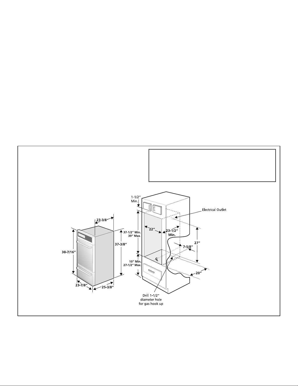
DIMENSIONS AND CLEARANCES
This unit is designed to fit various cutout sizes from
a minimum of 37 1/2” to 39”. See page 4 for proper
height adjustment.
• Do not use the oven as a store space. This creates a
potentially hazardous situation.
• The appliance requires fresh air for proper burner combustion. Do not obstruct the flow combustion air at the oven
vent or around the base or beneath the lower front panel
of the appliance. Avoid touching the event openings or
nearby surfaces, as they may become hot.
• Remember, your oven is not designed to heat your
kitchen. Such abuse could result in fire and/or damage to
the unit and will void your warranty .
• Do not store or use gasoline or other flammable vapors
and liquids near this or any other appliance. Explosions or
fires could result.
ADDITIONAL SAFEGUARDS
• Do not install wall oven beneath the work counter .
• The flue discharge shall not be located below the
36 inch level.
Allow at least 19 3/8” clearance for complete oven
door opening as shown in FIGURE 1.
2
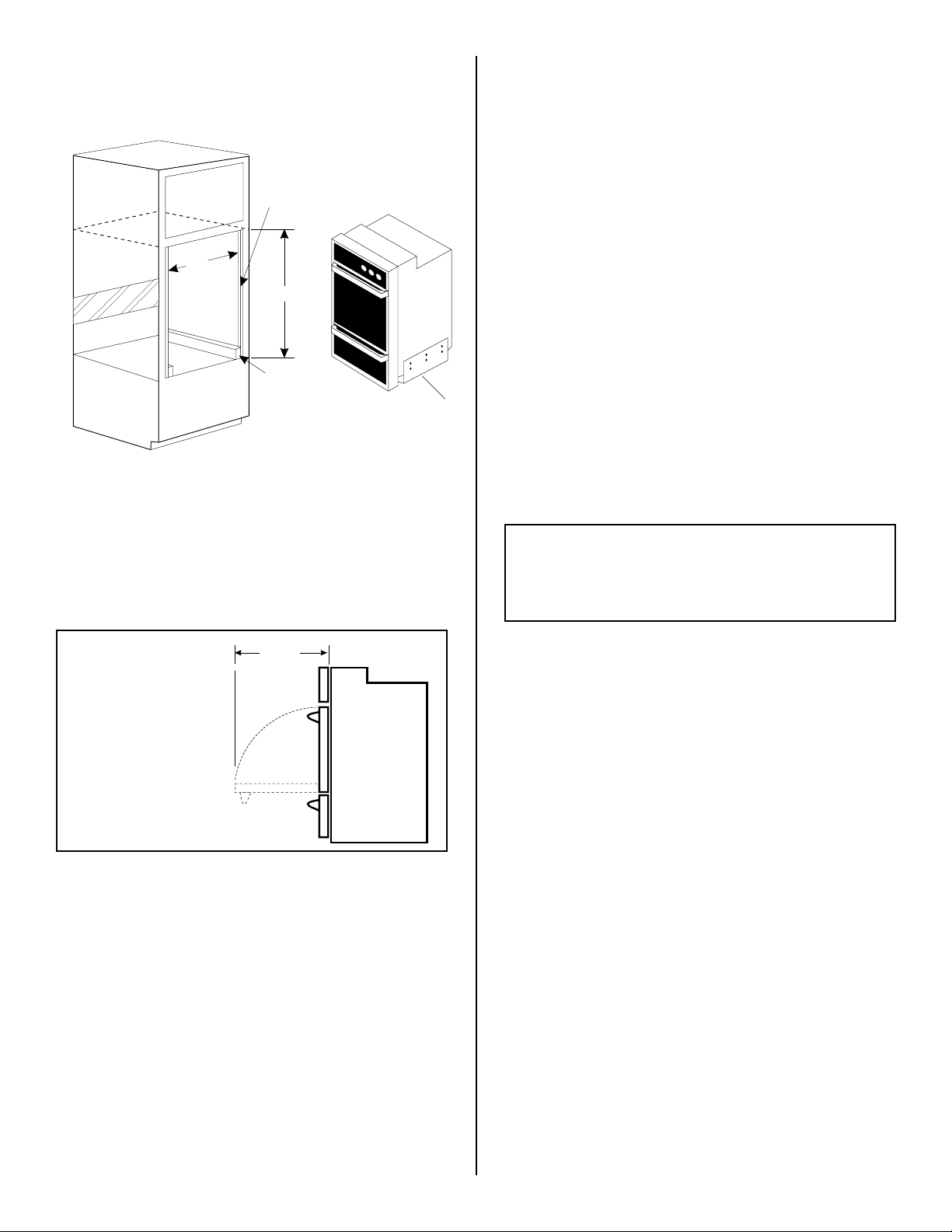
ALTERNATE CONSTRUCTION
Installation instructions for installing a 1 1/2 cavity
oven into an existing 2 cavity opening with dimensions 42 1/8” H. by 22 1/2” W.
2”
22 1/2”
42-1/8”
3”
1”
PROVIDE ADEQUA TE GAS SUPPLY
This oven is designed to operate on natural gas at 4” of
manifold pressure or on LP gas at 10” of manifold pressure.
It is shipped from the factory set for natural gas. If it is to be
used with LP gas, adjustments described on page 5 must be
made.
A convertible pressure regulator is connected in series with
the manifold of the oven and must remain in series with the
supply line regardless of whether natural or LP gas is being
used.
FOR PROPER OPERA TION, THE MAXIMUM INLET PRESSURE
TO THE REGULATOR MUST BE NO MORE THAN 14” OF
WATER COLUMN PRESSURE.
For checking the regulator, the inlet pressure must be at
least 1” (or 3.4 KPA) greater than the regulator manifold
pressure setting. If the regulator is set for 4” of manifold
pressure, the inlet pressure must be at least 5”. If the
regulator is set for 10”, the inlet pressure must be at least
11”.
1. Height adjuster - lower height adjuster 1”.
2. If width opening is too wide to secure unit to cabinet with
mounting screws, add filler strips.
3. 2” x 4” (
standard 1-1/2” x 3-1/2”
) 22” minimum - stand
upright and flush with front cabinet. Secure to floor or
wall.
4. Lower trim (not shown) - overlap cabinet front (at bottom
of cutout) 1/4” minimum.
19-3/8”
MINIMUM
REQUIREMENT
FOR
COMPLETE
OVEN DOOR
OPENING.
Figure 1
SIDE
VIEW
NORMAL INSTALLATION STEPS
CONSTRUCTION REQUIREMENTS
• Cabinet or wall opening must be 22” wide, 23 1/2”depth
from outside face of cabinet to rear of opening, and
37 1/2”. Corners must be square.
• Floor of cabinet must be able to support 150 pounds and
must be flush with bottom of opening.
The recess in which an oven or broiler unit is installed
shall be constructed so as to provide a complete
closure around the recessed portion of the appliance,
and that any openings around gas and electric service
outlets shall be closed at the time of installation.
The gas supply line to the oven should be 1/2” or 3/4” pipe.
ELECTRICAL GROUNDING INSTRUCTIONS
WARNING:
This appliance is equipped with a three-prong grounding plug
for your protection against shock hazard and must be plugged
directly into a properly grounded receptacle. Do not cut or
remove grounding prong from this plug.
Use a properly polarized and grounded three-hole receptacle as is required by the National Electrical Codes on all
new construction.
Where a standard two-prong wall receptacle is encountered,
it is the personal responsibility and obligation of the
consumer to have it replaced with a properly grounded
three-prong wall receptacle.
INSTALLATION
Remove and lay aside the lower vent grille that is taped to
the outer side panel of the oven. The grille will be fastened
to the lower front of the cabinet after it has been installed in
the cabinet.
Insert appliance into cut-out. Screws in the miscellaneous
parts bag are provided for fastening the front frame on the
appliance to the cabinet. The mounting holes in the front
frame of appliance may be used as a template to locate the
appliance mounting screw holes.
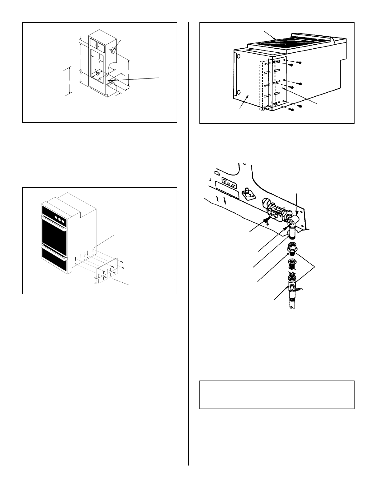
To fasten the appliance to the cabinet (see figure 2):
Use screws for mounting the appliance in the mounting
holes on each side of the oven frame, above the door.
To fasten the lower oven grille under the oven:
1. After oven has been adjusted to desired height, align
grille.
2. Mount grille to bottom of cabinet using 2 screws from the
miscellaneous parts bag.
3
MTG. SCREW
MTG. SCREW
LOWER VENT GRILL
MTG. SCREW
MTG. SCREW
OVEN DOOR
OVEN BOTTOM
EXTENSION
PANEL
Figure 2
HEIGHT ADJUSTMENT ON OVEN
There is a 1 1/2” height adjustment on these models. (see
figure 3) With this adjustment and a 1/2” trim overhang, a
unit can be installed in existing openings 37 1/2” to 39”
high.
ADJUSTMENT
HOLES
EXTENSION
PANEL
MOUNTING
SCREWS
Figure 3
Figure 4
CONNECT THE OVEN TO GAS
SHUT-OFF
VALVE
PRESSURE REGULATOR
SHUT-OFF VALVE
3/8” NIPPLE
ADAPTOR OR UNION
EXTERNAL
SHUT-OFF VALVE
SOLID PIPE
OR FLEX
CONNECTOR
To adjust oven height:
A. Lay oven on its back. (see figure 4).
B. Remove the 6 screws that fasten the side extension
panel to the bottom sides of the oven.
C. Move each panel down to the position that increase
the oven height to fit your opening. Each position changes
oven height approximately 1/2”.
D. Line up the appropriate holes in the side extension
panels and sides of the oven. Replace the 6 screws.
E. Proceed with oven installation. Return oven to upright
position.
4
Figure 5
If flexible gas connector is used, gas line must be
AGA design certified.
Install a manual shutoff valve in the gas line in an easily
accessible location outside of the oven. Be sure you know
how and where to shut off gas supply to the oven.
IMPORTANT: A pipe joint sealant resistant to the action
of LP gas, must be employed on the pipe connections.
Check for leaks. After connecting the oven to gas, check
the system for leaks with a manometer. If a manometer is
not available, turn the gas supply on to the oven and use a
liquid leak detector at all joints and connections to check for
leaks.
Tighten all connections if necessary to prevent gas
leakage in the oven or supply line.

CAUTION: DO NOT USE A FLAME TO CHECK FOR
GAS LEAKS.
Do not remove the pressure regulator.
Disconnect this oven and its individual shutoff valve
from the gas supply piping system during any pressure
testing of that system at test pressures greater than 1/2 psig.
Isolate the oven from the gas supply piping system, by
closing its individual manual shutoff valve during any
pressure testing of the gas supply piping system at test
pressures equal to or less than 1/2 psig.
CHECK THE IGNITERS
Operation of electric igniters should be checked after oven
and supply line connectors have been carefully checked for
leaks and oven has been connected to electric power.
OVEN IGNITER SYSTEM
Close the door and turn the OVEN TEMP knob to 300°F. In
approximately 60 seconds, the burner should ignite and stay
on until oven reaches 300°F. Burner should then cycle on and
off to maintain an average temperature of approximately
300°F.
HOW TO CONVERT THE OVEN FOR USE
WITH LP GAS
CONVERT THE PRESSURE REGULA TOR
Do not remove the pressure regulator.
Remove broiler or storage drawer by pulling drawer out to
stops. Lift drawer front to clear stops and pull out.
GASKET
SMALL END TOWARDS
REGULATOR FOR
NATURAL GAS
ENLARGED END
TOWARDS REGULATOR
FOR L.P. GAS
Figure 6
ADJUST OVEN BURNER ORIFICE
FOR LP GAS:
AIR SHUTTER
OVEN BURNER
SPUD
Figure 7
Using 1/2” wrench, turn down the adjustable spud which injects
gas into the oven burner. Turn this spud until snug against the
LP metering pin. This will be approximately 2-1/2 turns. Do not
overtighten. See figure 7.
Pin
Nat.
L.P.
Pin
Spud
Locate pressure regulator on lower back wall and convert as
shown in Figure 6.
1. Remove the cap from the pressure r egulator.
2. Remove the plunger from the cap.
3. Turn the plunger upside down with the enlarged end
down.
4. Replace the plunger back into the cap. “LP” should be
visible on the explosed end of plunger .
5. Replace the cap with gasket on regulator.
NOTE: THE TYPE OF GAS PRESSURE THE REGULATOR
IS SET FOR INDICATED ON THE TOP OF THE PLUNGER
Figure 8
Nat.
Spud
AIR SHUTTER
L.P.
WAIST-HIGH
BROILER SPUD
ADJUST BROIL BURNER ORIFICE FOR LP
GAS (Self Cleaning Models Only):
Using 1/2” wrench, turn down the adjustable spud which injects
gas into the oven burner. Turn this spud until snug against the
LP metering pin. This will be approximately 2-1/2 turns. Do not
overtighten. See figure 8.
5

ADJUST THE OVEN/BROILER BURNER
FLAME
CAUTION: POWER FAILURE
Adjust the air shutter. It is
located on the venturi
tube, which sets on the
hood of the valve, and is
locked in place with a
Phillips head screw. If it
needs adjusting, loosen
the screw and rotate the
shutter to allow more or
less air into the burner
tube. See Figure 8
To determine if the oven
burner flame is proper,
observe the flame. It
should be steady with approximately 1” blue
cones and the fame
should not extend out
over the edges of baffle. For LP gas, this will most likely
occur when the air adjustment shutter is completely open.
See Figure 9.
T urn OVEN TEMP knob to 300°F and allow oven to cycle on
and off.
To replace broiler drawer or lower bottom, reverse steps
taken for removal. Replace oven rack and/or broiler pan.
AIR
ADJUSTMENT
SHUTTER
Figure 8
Figure 9
LOOSEN
DO NOT attempt to operate the oven in the event
of a power failure. If a power failure should occur
during operation, turn the oven control to the off
position. Failure to turn the oven control off will
result in oven operation upon resumption of
power to the unit.
SERIAL PLATE LOCATION
The Serial Plate is located on the left side inner trim of the
oven.
When ordering parts for or making inquiries about your appliance, always be sure to include the model and serial
numbers and a lot number or letter from the serial plate on
your appliance. Refer to the Owner’s Manual for complete
instructions.
Y our serial plate also tells you the ratings of the burners
and type of fuel and pressure the appliance was adjusted
for when it left the factory .
BEFORE YOU CALL FOR SERVICE
Check to make sure the house fuses or circuit breaker for
your oven are not blown or open.
NOTE: Refer to Owner’s Guide for operating instructions and cleaning instructions.
CARE CLEANING AND MAINTENANCE
If removing the unit is necessary for cleaning or maintenance, shut off gas supply. Disconnect the gas supply line.
Remove installation screws from front frame and lower
grille. Pull out only as far as necessary to disconnect the
electric supply line. After disconnecting the gas and electric
supply, finish removing the unit for servicing and cleaning.
Reinstall in reverse order making sure to level the appliance
and check gas connection for leaks.
WARNING: Stepping, leaning or sitting on the
doors or drawers of this appliance can result in
serious injuries and also cause damage to the
appliance.
AFTER INSTALLATION IS COMPLETE MAKE SURE ALL
CONTROLS ARE LEFT IN THE OFF POSITION.
Reset all controls to the “OFF” position after using a
programmable timing operation.
6

INSTRUCCIONNES PARA LA INSTALACIÓN
HORNO EMPOTRADO A GAS
MODELOS REGULARES Y AUTOLIMPIADORES
LA INST ALACIÓN Y EL SERVICIO DEBEN SER REALIZADOS POR UN INSTALADOR CALIFICADO.
AVISO IMPORTANTE ANTES DE EMPEZAR - LEA CON ATENCIÓN TODAS ESTAS INSTRUCCIONES.
PARA EL INSTALADOR: NO SE OLVIDE DE DEJAR ESTAS INSTRUCCIONES CON EL USUARIO.
AVISO IMPORTANTE GUARDE ESTAS INSTRUCCIONES CON EL LIBRO DE MANTENIMIENTO Y UTILIZACIÓN PARA
PARA EL USUARIO: FUTURAS REFERENCIAS.
SIGA TODAS LAS INDICACIONES Y LOS CÓDIGOS VIGENTES.
GUARDE ESTAS INSTRUCCIONES PARA LOS INSPECTORES LOCALES.
ADVERTENCIA: Si todas las instrucciones de éste manual no son observadas a la letra, se puede
ocurrir incendios o explosiones que pueden causar daños materiales, lesiones o la muerte.
- No almacene o utilice gasolina u otros vapores y líquidos inflamables cerca de este o
cualquier otro artefacto.
- QUE HACER SI HAY FUGAS DE GAS
• No intente de encender ningún artefacto.
• No toque ningún interruptor eléctrico; no utilice ningún aparato telefónico en
su edificio.
• Llame inmediatamente el abastecedor de gas desde el telefónico de un vecino.
Siga las instrucciones del abastecedor de gas.
• En caso que no puede contactar el abastecedor de gas, llame al departamento
de bomberos.
- La instalación y el servicio tëcnico deben ser realizados por un instalador
calificado, por un servicio tëcnico certificado o por el abastecedor de gas.
NO TRAIGA DE PONER EL HORNO
EMPOTRADO EN FUNCIONAMIENTO DURANTE UN CORTE DE ENERGÍA.
IMPORTANTE
Retire todos los artículos de embalaje y folletos de la
cocina antes de realizar la conexiones de gas y
eléctricas a la cocina.
SE ADJUNTA EL DIAGRAMA DE
CABLES DE ESTA COCINA EN EL
SOBRE CON EL CATÅLAGO.
en Canadá
318201502 (9810) Rev. AImpreso
INSTRUCCIONES DE SEGURIDAD IMPORT ANTES
La instalación de esta cocina debe realizarse en
conformidad con los códigos locales o, si éstos no existen,
con el National Fuel Gas Code ANSI Z223.1 - última edición.
El diseño de esta cocina cuenta con la aprobación de la
American Gas Association. Al igual que todos los artefactos
a gas que generan calor , deben seguirse ciertas medidas de
seguridad. Vienen con el Manual de uso y mantenimiento.
Lea el manual atentamente.
• Asegure que la cocina sea instalada correctamente por un
instalador o técnico calificado.
• La cocina debe conectarse eléctricamente a tierra de
acuerdo con los códigos locales o, de no existir, con el
código eléctrico ANSI/NFP A No. 70 - última edición. Mir e
las instrucciones de conexión a tierra en la página 3.
• La instalación de unidades diseñadas para casas
(movibles) deben cumplir con los estandares de “Manufactured Home Construction and Safety Standard, title 24
CFR part 3280”. Anteriormente “The Federal Standard
for Mobile Home Construction and Safety title 24. HUD
(Part 280)”. O cuando estos estandares no sean
aplicables: “The Standard for Manufactured Home Installation 1982, (Manufactured Home Sites, Communities
and set-ups), ANSI Z225. NFP A - 501 A”, última edición o
códigos y regulaciones locales.

INSTRUCCIONES DE
SEGURIDAD IMPORTANTES
• Asegurese de remover todo el material de embalaje del
aparato antes de hacerlo funcionar, para evitar fuego o
daños por humo, en caso que el material de embalaje se
encendió.
• No permita que los niños estén solos en la cocina cuando
la estufa esté en uso. No les permita sentarse o pararse
en ninguna parte de la estufa, pues podrían lastimarse o
quemarse. Asegúrese de que no toquen la puerta del
horno o la ventana de vidrio cuando el horno esté en uso,
ya que éstas partes se calientan lo suficiente como para
causar quemaduras serias.
• Aviso: No almacene alimentos u otros objetos de interés
para los niños en alacenas ubicadas encima de la estufa o
en la guarda posterior de esta. Los niños pueden
quemarse o lastimarse seriamente si se suben en la estufa
para alcanzar estos objetos.
DIMENSIONES Y ESPACIOS LIBRES
Esta unidad esta diseñada para ajustarse a varios
tamaños de cortes, desde un mínimo de 37-1/2”
hasta 39” para modelos con 1-1/2 cavidades o de
50-1/4” hasta 51-3/4” para modelos con 2 cavidades.
Mire la pagina 4 para la abertura correcta.
• Remueve la bandeja del asador y otros utensilios antes de
usar el ciclo de limpieza a si mismo.
• No use el horno como espacio de almacenamiento. Esa
situación puede ser peligrosa.
• La estufa requiere aire fresco para que el quemador haga
la combustión adecuadamente. No obstruya la circulación
de aire de combustión en las ventilaciones del horno, ni
alrededor de la base, ni debajo del tablero frontal de la
estufa. Evite tocar las aberturas de ventilación y las
superficies cercanas pues éstas pueden calentarse.
• Recuerde, su horno no ha sido diseñado para calentar la
cocina. Este abuso puede causar un incendio o daño de la
unidad y anularía la garantía.
• No guarde o haga uso de gasolina o otros vaporos y
líquidos inflamables acerca de esté o cualquier aparato.
Se puede resultar en incendios o explosiónes.
MEDIDAS DE SEGURIDAD ADCIONALES
• No instale horno de pared debajo de la mesa de
trabajo.
• La salida de descarga no debe estar por debajo de
36”de altura.
PERFORACIÓN
DE 1-1/2”
PARA
CONEXIÓN
DE GAS
SALIDA
ELECTRICA
Medida mínima requisita para que la puerta del horno se
abre completamente, como se muestra en la FIGURA 1.
2

ALTERNATIVA DE CONSTRUCCION
Instrucciónes para instalar un horno de 1-1/2 cavidades en una
abertura existente para horno de 2 cavidades con dimensiónes
de 42-1/8” de alto por 22-1/2” de ancho.
2”
22 1/2”
1. Ajuste de altura - ajuste inferior de altura de 1”.
2. Si la abertura es demasiodo ancha para fijar la unidad al gabinete
con tornillos de montaje, ajuste con las tiras de relleno.
3. 2” x 4” (
nivele con el frente del gabinete. Asegure al suelo o al pared.
4. Moldura inferior (no se muestra) - monte al menos 1/4” sobre el
frente del gabinete (en parte inferior de abertura).
1-1/2” x 3-1/2”
standard) 22” mínimo - pare al derecho,
42-1/8”
3”
19-3/8”
PROVEA UN ADECUADO SUMINISTRO DE GAS
Esta cocina ha sido diseñada para utilizar gas natural de 4” de presión
múltiple, o para utilizar gas PL/Propano de 10” de presión múltiple.
De fábrica viene para usarse con gas natural. Para que se pueda
usar con gas PL/propano, siga las instrucciones de la página 5.
Un regulador de conversión de presión en serie esta conectado con el
múltiple del horno, y debe permanecer en serie con la línea de
suministro de gas, no importa si esta usando gas natural o gas
PL/propano.
PARA QUE MANEJO CORRECTO, LA PRESIÓN DE ENTRADA
MÁXIMA HACIA EL REGULADOR NO DEBE EXCEDER 14” DE
PRESIÓN DE LA COLUMNA DE AGUA.
Para controlar el regulador, la presión de entrada debe ser de al
menos 1” (o 3.4 KPA) mayor que el ajuste de la presión del múltiple
del regulador. Si el regulador se ajusta a 4” de la presión del
múltiple, la presión de entrada debe de ser de al menos 5”. Si el
regulador se ajusta a 10” de la presión del múltiple, la presión de
entrada debe de ser de al menos 11”.
La línea de suministro de gas por el horno deberá tener un tubo de
1/2” o de 3/4”.
1”
INSTRUCCIONES P ARA INST ALACION DE TIERRA
ADVERTENCIA:
Para su protección contra choques eléctricos este aparato ha sido
equipado con un enchufe de tres patas con conexión a tierra
apropiada. No remueva la pata redonda de tierra de este enchufe.
Use un toma de tres huecos, polarizado y con una tierra
correctamente instalada como lo requiere el “National Electric Codes”
para toda nueva construcción.
Dónde se encuentre un toma standard de dos patas, será responsabilidad personal y obligación del comprador reemplazarlo por un
toma de tres patas conectado a tierra.
MEDIDA MÍNIMA
REQUISITA PARA
QUE LA PUERTA
DEL HORNO
SE ABRE
COMPLETAMENTE
Figura 1
VISTA
LATERAL
INSTRUCCIONES PARA UNA
INST ALACIÓN NORMAL
REQUISITOS DE CONSTRUCCIÓN
• La abertura del gabinete o de la pared debe ser de 22 pulgadas de
ancho, 23 y 1/2 pulgadas de profundidad desde la cara exterior de
gabinete hasta la parte posterior de la abertura, y 37 y 1/2. Las
esquinas deben estar cuadradas.
• El piso del gabinete debe soportar una carga de 150 libras y debe
estar nivelado con el fondo de la abertura.
El soporte en el cual un horno o un asador es instalado deberá
ser construido de tal manera que proporcione un cerramiento
total alrededor de la parte apoyada del electrodoméstico.
Además, cualquier abertura alrededor de las entradas de gas o
de electricidad debe ser sellada al momento de la instalación.
INSTALACIÓN
Retire y ponga a un lado la rejilla baja de ventilación que está
pegada a la parte exterior del panel del horno. La rejilla será fijada
a la parte de baja del frente del gabinete después de que éste haya
sido instalado en el gabinete.
Inserte el electrodoméstico en la abertura. Para atornillar el marco
frontal del electrodoméstico en el gabinete, encontrará los tornillos
en la bolsa de partes varias. Los huecos de montaje en el frente
del marco del electrodoméstico pueden ser usados como una
plantilla para localizar los huecos para los tornillos para el montaje
del electrodoméstico.
Para fijar el electrodoméstico al gabbinete (ver figura 2)
Utilice los tornillos para el montaje del elctrodoméstico en los
huecos de montaje en cada lado del marco frontl del horno, por
debajo de la puerta del horno.
Para fijar la rejilla inferior del orno bajo el horno:
1. Después de que el horno haya sido ajustado a la altura deseada,
alinee la rejilla.
2. Monte la rejilla al fondo del gabinete usando 2 tornillos de la bolsa
de partes varias.
3

TORNILLOS DE
MONTAJE
PUERTA DEL HORNO
TORNILLOS DE
MONTAJE
REJILLA PARA LA
VENTILACIÓN POR
ABAJO
TORNILLOS
DE MONTAJE
TORNILLOS DE
MONTAJE
Figura 2
AJUSTE DE AL TURA DEL HORNO
Este modelos de horno cuenta con un ajuste de altura de 1-1/2”
(ver figura 3). Con este ajuste y la pestaña de 1/2” el horno puede
ser instalado en aberturas existentes de 37-1/2” a 39” de altura.
PERFERACIONES PARA
AJUSTAR
PANEL DE
EXTENSIÓN
TORNILLOS DE
MONTAJE
PANEL DE
FONDO DEL HORNO
EXTENSIÓN
Figura 4
CONEXION DEL HORNO AL SUMINISTRO DE GAS
VALVULA
DE CIERRE
REGULADOR DE PRESION
VALVULA DE CIERRE
TUBERÍA
3/8 NIPLE
ADAPTOR O UNION
RIGIDA O
CONECTOR
FLEXIBLE
Figura 3
Para ajustar la altura del horno:
A. Coloque el horno sobre su parte posterior (ver figura 4).
B. Remueva los 6 tornillos que aseguran el panel lateral de
extensión a la partes laterales inferiores del horno.
C. Mueva cada panel hasta la posición que mejor ajuste la
altura del horno al tamaño de su abertura. Cada posición
cambia la altura del horno aproximadamente 1/2”.
D. Alinée los orificios del panel lateral de extensión con los
de las paredes laterales del horno. Vuelva a colocar los 6 tornillos.
E. Proceda con la instalación del horno. Vuelva a colocar el
horno sobre su base.
4
VALVULA EXTERIOR
DE CIERRE
Figura 5
Si se utiliza conector de gas flexible, la linea de gas deberá
ser de diseño AGA certificado.
Instale una válvula de cierre manual en un sitio de fácil
acceso en la parte exterior del horno. Asegúrese de saber de
dónde y como cerrar el suministro de gas del horno.
IMPORTANTE: En las uníones de la tuberia debe usarse
un sellante de uníon de tuberia que sea resistente a la acción
del gas LP.
Verifique si hay fugas. Luego de conectar la cocina al gas,
verifique el sistema con un manómetro. Si no cuenta con este
instrumento, dé la vuelta al suministro de gas de la cocina y
utilice un detector de fugas líquidas en todas las articulaciones y
conexiones para verificar si existen fugas.
Ajuste todas las conexiones en caso que sea necesario, para
evitar fugas de gas en la cocina o en el tubo de suministro de
gas.

AVISO: NO USE NINGÚN TIPO DE LLAMA PARA
VERIFICAR SI HAY FUGAS DE GAS.
No remueva el regulador de presión.
Desconecte la cocina y su válvula de cierre individual del
sistema de tubería del suministro de gas durante cualquier
ensayo de presión del sistema en ensayos de presión superiores
a 1/2 psig.
Aparte la cocina del sistema de tubería del suministro
de gas, cierrando su válvula de cierre individual manual,
durante cualquier ensayo de presión del systema de suministro
de gas en ensayos iguales o inferiores a 1/2 psig.
VERIFIQUE LOS DISPOSITIVOS DE ENCENDIDO
La manipulación de los dispositivos de encendido eléctrico
deberá verificarse tras haber revisado detenidamente la cocina y
los conectores del tubo del suministro de fugas y tras haber
conectado la cocina al suministro eléctrico.
SISTEMA DE ENCENDIDO DEL HORNO
Cierre la puerta del horno y gire el boton de OVEN TEMP
(temperatura del horno) a 300°F. En 60 segundos aproximadamente, el quemador debe prender y permanecer encendido
hasta que el horno alcance 300°F. El quemador seguirá
alternando entre encendido y apagado para mantener una
temperatura promedia de aproximadamente 300°F.
COMO CONVERTIR LA COCINA PARA
QUE SE PUEDA USAR CON GAS LP/
PROPANO
CONVIERTA EL REGULADOR DE PRESIÓN
No remueva el regulador de presión
Remueva el asador o el cajón de almacenamiento halandolo
hacia afuera hasta los topes, luego saque hacia afuera.
Localice el regulador de presión en la parte inferior de la pared
trasera y modifique como se muestra en la figura 8.
1. Remueva la tapa del regulador de presión.
2. Remueva el pistón de la tapa.
3. Dé la vuelta al pistón, poniendo la grande extremidad hacia
abajo.
4. Vuelva a poner el pistón dentro de la tapa. Las letras “LP”
deben de estar visibles en la extremidad descubierta del
pistón.
5. Vuelva a poner la tapa del regulador.
JUNTA
PEQUEÑA EXTREMIDAD
HACIA EL REGULADOR
PARA GAS NATURAL
GRANDE EXTREMIDAD
HACIA EL REGULADOR
PARA GAS LP
Pasador
Figura 6
AJUSTE DEL ORIFICIO DEL
QUEMADOR DEL HORNO P ARA
GAS LP:
Obturador de aire
Junta en forma
de bellota del
quemador
Figura 7
L.P.
Nat.
Junta en
forma de
Usando una llave de 1/2 pulgada, giro hacia abajo la junta en
forma de bellota ajustable que inyecta gas al quemador del
horno. Gire esta junta en forma de bellota hasta que ajuste
contra el pasador medidor de L.P. Esto será aproximadamente 2
1/2 vueltas. No lo apriete damasiado. Ver Figura 7.
Pasador
Figura 8
Nat.
Junta en
forma de
bellota
Obturador de aire
L.P.
Junta en forma de
bellota de la parrilla
bellota
NOTA: EL TIPO DE PRESIÓN DE GAS PARA EL CUAL HA
SIDO CALIBRADO EL REGULADOR ESTA INDICADO EN LA
PARTE SUPERIOR DEL PISTÓN.
AJUSTE DEL ORIFICIO DEL QUEMADOR
DEL ASADOR PARA GAS L.P.
(modelos autolimpiadores solamente):
Usando una llave de 1/2 pulgada, gire hacia abajo la junta en
forma de bellota ajustable que inyecta gas al quemador del
horno. Gire esta junta en forma de bellota hasta que ajuste
contra el pasador de medición de L.P. Esto será aproximadamente 2 1/2 vueltas. No lo apriete demasiado. Ver figura 8.
5

AJUSTE DE LA LLAMA DEL
QUEMADOR DEL HORNO/ASADOR
Ajuste el obturador de aire.
Esté está localizado en el
vénturi, jundo a la capucha
de la válvula y es fijado en
su lugar pour un tornillo
con cabeza tipo Phillips. Si
éste necesita ajuste, afloje
el tornillo y rote el obturador para permitir más o
menos aire en el tubo del
quemador. Ver Figura 8.
Para determinar si la llama
del quemador del horno es la
apropiada, observe la llama.
Esta debe estar estable
formando conos azules de 1
pulgada aproximadamente.
La llama no debe extenderse
por encima de los bordes del
resonador. Para gas LP, ésto
ocurre más frecuentemente cuando el obturador de ajuste
de aire está completamente abierto. Ver figura 9.
Ponga el botón de OVEN TEMP (temperatura del horno) en
300°F, y permita que el horno alterne entre “on” y “off”
(prendido y apagado).
OBTURADOR
DE AIRE
Figura 8
Figura 9
FLOJO
AVISO: CORTE DE ENERGÍA ELÉCTRICA
NO TRATE de usar el horno de encendido eléctrico
durante un corte de energía . En caso de un corte de
energía eléctrica cuando el horno esta en funcionamiento coloque todos los controles en posición
APAGADO. El reestablecimiento del servicio eléctrico
cuando los controles del horno están en cualquier posición
diferente a APAGADO causaría el encendido automático del
quemador del horno.
MODELO Y UBICACIÓN DEL NÚMERO DE SERIE
La placa de numero de serie está ubicada en el lado de abajo
del armazón del horno.
Asegúrese de incluir el modelo, número de serie y el número o
letra del lote que se encuentran en la placa de serie de su
estufa, en todo pedido de partes o solicitud de información
acerca de su estufa.
La placa de número de serie también indica las especificaciones
de los quemadores, el tipo de combustible y la presión para la
cual fué ajustada la estufa en la fábrica.
ANTES DE LLAMAR
AL SERVICIO TÉCNICO
Verifique que los fusibles de la casa no se hayan fundido o el
cortacircuitos del horno no hayan saltado o abierto.
Para volver a colocar el cajón o el fondo inferior del asador,
siga en forma inversa los poasos tomados para retirarlo.
Vuelva a colocar la parrilla del horno y/o la bandeja del asador.
NOTA: Consulte el Manual de usuario para las
instrucciones de funcionamiento y limpieza.
CUIDADO, LIMPIEZA
Y MANTENIMIENTO
Cierre el suministro de gas en caso de ser necesario remover la
unidad para su limpieza o reparación. Desconecte la linea de
suministro de gas. Remueva los tornillos de instalación del
marco frontal y la parrilla inferior. Hale hacia afuera apenas lo
necesario para poder desconectar del toma eléctrico. Después
de desconectar del suministro eléctrico y de gas, termine de remover la unidad para su limpieza o mantenimiento. Reinstale
siguiendo el procedimiento inverso. Asegúrese de nivelar la
estufa y verificar que no halla escapes en la conexión de gas.
ADVERTENCIA: Pararse, apoyarse o sentarse en las
puertas o cajones de esta estufa puede causar serias
lesiones personales y también puede dañar la estufa.
CUANDO SE HAN REALIZADO TODOS LOS SISTEMAS DE
CONEXIÓN ASEGURESE QUE TODOS LOS CONTROLES
ESTÁN EN LA POSICIÓN DE APAGADO (OFF).
Vuelva a colocar todos los controles en la posición de
“off” (apagado) después de utilizar el funcionamiento de
programación cronometrada.
6
 Loading...