

Page 1
INSTALLATION INSTRUCTIONS - FREESTANDING GAS RANGE
INSTALLATION AND SERVICE MUST BE PERFORMED BY A QUALIFIED INSTALLER.
IMPORTANT: SAVE FOR LOCAL ELECTRICAL INSPECTOR’S USE. READ AND SAVE THESE
INSTRUCTIONS FOR FUTURE REFERENCE.
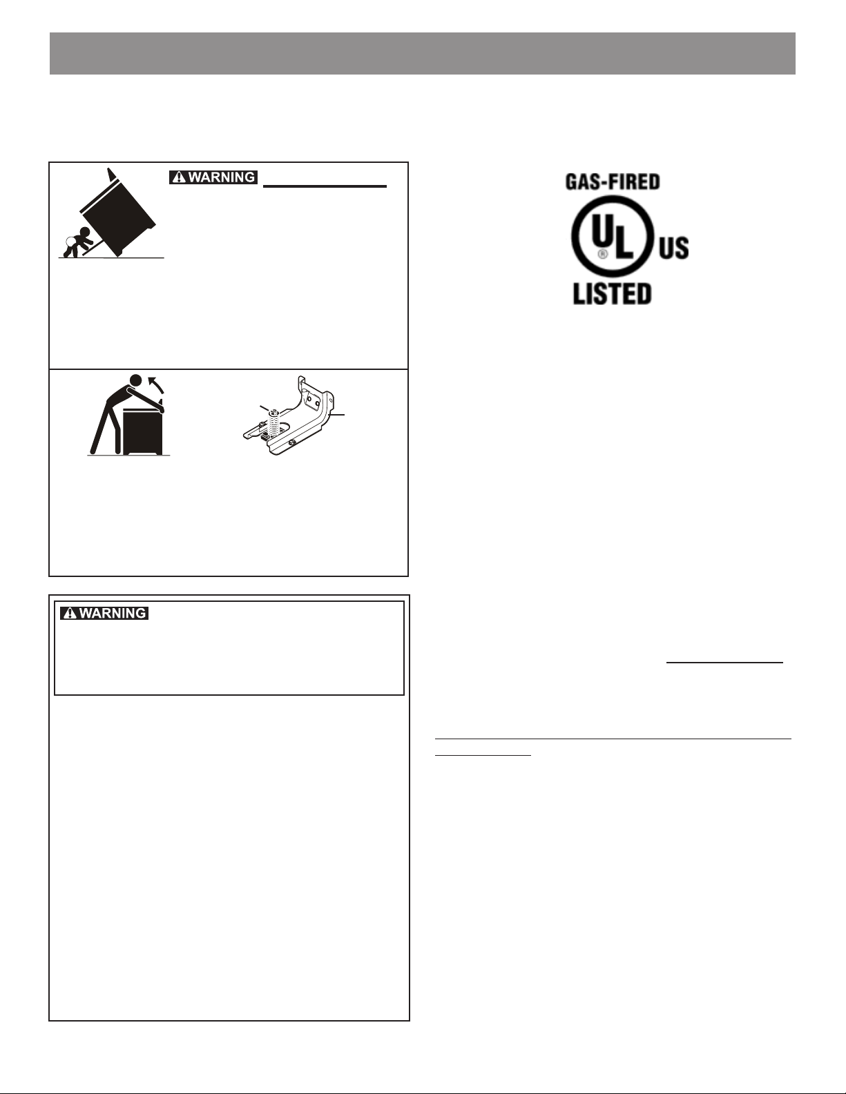
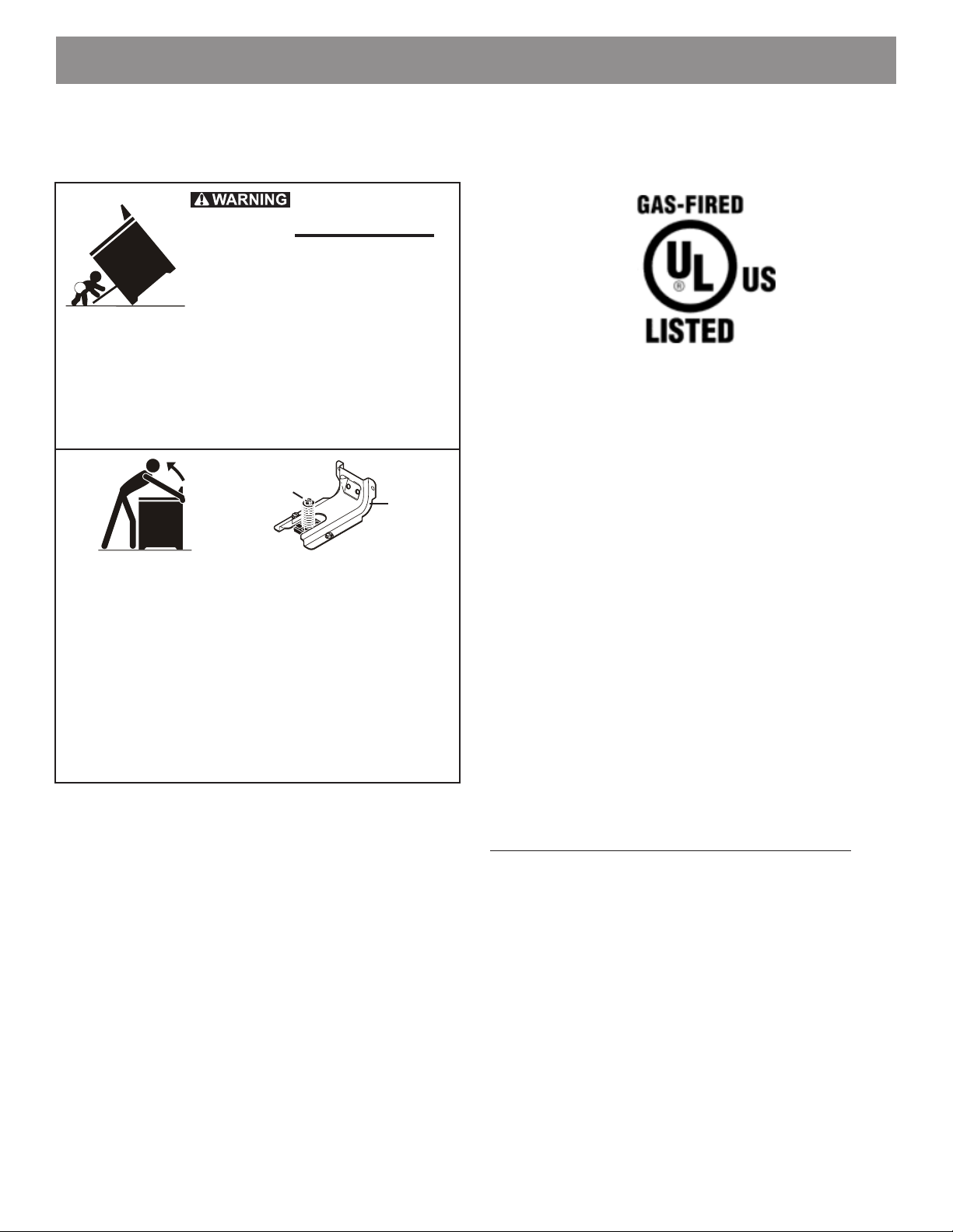
Tip Over Hazard
• A child or adult can tip the range
and be killed.
• Verify the anti-tip device has been
installed to oor or wall.
• Ensure the anti-tip device is re-engaged when the
range is moved to oor or wall.
• Do not operate the range without the anti-tip device in
place and engaged.
• Failure to follow these instructions can result in death
or serious burns to children and adults.
Range
leveling leg
To check if the anti-tip bracket is installed properly,
use both arms and grasp the rear edge of range back.
Carefully attempt to tilt range forward. When properly
installed, the range should not tilt forward.
Refer to the anti-tip bracket installation instructions
supplied with your range for proper installation.
Anti-Tip
bracket
If the information in this manual
is not followed exactly, a re or explosion may
result causing property damage, personal
injury or death.
FOR YOUR SAFETY:
— Do not store or use gasoline or other
flammable vapors and liquids in the
vicinity of this or any other appliance.
— WHAT TO DO IF YOU SMELL GAS:
• Do not try to light any appliance.
• Do not touch any electrical switch; do not
use any phone in your building.
• Immediately call your gas supplier from
a neighbor’s phone. Follow the gas
supplier’s instructions.
• If you cannot reach your gas supplier, call
the re department.
— Installation and service must be performed
by a qualied installer, service agency or
the gas supplier.
Refer to your serial plate for applicable agency
certications
Provide proper fuel type
Before proceeding: Your range is factory preset to oper-
ate on natural gas. If L.P. conversion is needed, contact
your local L.P. Gas provider for assistance.
Important notes to the installer
• Read all instructions contained in these installation
instructions before installing range.
• Remove all packing material from the oven
compartments before connecting the gas and electrical
supply to the range.
• Observe all governing codes and ordinances.
• Be sure to leave these instructions with the consumer.
Important notes to the consumer
• Keep these instructions with your Use & Care Guide
for future reference.
• Be sure your range is installed and grounded properly
by a qualied installer or service technician.
Special instructions for appliances installed in the State of
Massachusetts:
This appliance can only be installed in the State of
Massachusetts by a Massachusetts licensed plumber or
gas tter. When using a exible gas connector, it must
not exceed 3 feet (36 inches) in length. A “T” handle type
manual gas valve must be installed in the gas supply line
to this appliance.
1
809019203 Rev B (1901)
Page 2
INSTALLATION INSTRUCTIONS - FREESTANDING GAS RANGE
IMPORTANT SAFETY INSTRUCTIONS
• Installation of this range must conform with local codes
or, in the absence of local codes, with the National
Fuel Gas Code ANSI Z223.1—latest edition when
installed in the United States.
• When installed in a manufactured (mobile) home,
installation must conform with the Manufactured Home
Construction and Safety Standard, Title 24 CFR, Part
3280 [formerly the Federal Standard for Mobile Home
Construction and Safety, Title 24, HUD (Part 280)] or,
when such standard is not applicable, the Standard
for Manufactured Home Installations, ANSI/NCSBCS
A225.1, or with local codes.
• This range has been design certied by Underwriters
Laboratories (UL). As with any appliance using
gas and generating heat, there are certain safety
precautions you should follow. You will nd them in the
Use & Care Guide; read it carefully.
• Be sure your range is installed and grounded properly
by a qualied installer or service technician.
• This range must be electrically grounded in
accordance with local codes or, in their absence, with
the National Electrical Code ANSI/NFPA No .70—
latest edition when installed in the United States. See
Grounding Instructions on page 8.
• Before installing the range in an area covered with
linoleum or any other synthetic oor covering, make
sure the oor covering can withstand heat at least
90°F above room temperature without shrinking,
warping or discoloring. Do not install the range over
carpeting unless you place an insulating pad or sheet
of 1/4-inch thick plywood between the range and
carpeting.
• Make sure the wall coverings around the range can
withstand the heat generated by the range.
• Do not obstruct the ow of combustion air at the oven
vent nor around the base or beneath the lower front
panel of the range. Avoid touching the vent openings
or nearby surfaces as they may become hot while the
oven is in operation. This range requires fresh air for
proper burner combustion.
• Air curtain or other overhead range hoods, which
operate by blowing a downward air ow on to a range,
shall not be used in conjunction with gas ranges other
than when the hood and range have been designed,
tested and listed by an independent test laboratory for
use in combination with each other.
DO NOT MAKE ANY ATTEMPT TO
OPERATE THE ELECTRIC IGNITION OVEN DURING
AN ELECTRICAL POWER FAILURE. RESET ALL OVEN
CONTROLS TO “OFF” IN THE EVENT OF A POWER
FAILURE.
The electric ignitor will automatically re-ignite the oven
burner when power resumes if the oven thermostat control
was left in the “ON” position.
When an electrical power failure occurs during use, the
surface burners will continue to operate.
During a power outage, the surface burners can be lit with
a match. Hold a lighted match to the burner, then slowly
turn the knob to the LITE position. Use extreme caution
when lighting burners this way.
Never leave children alone or
unattended in the area where an appliance is in use. Teach
children the proper, safe use of all appliances. Never leave
the oven door open when the range is unattended.
Stepping, leaning or sitting on the doors or
drawers of this range can result in serious injuries and can
also cause damage to the range.
• Be sure to keep the appliance clear of combustible
materials, gasoline, and other ammable vapors and
liquids.
• Do not store items of interest to children in the
cabinets above the range. Children could be seriously
burned climbing on the range to reach items.
• To eliminate the need to reach over the surface
burners, cabinet storage space above the burners
should be avoided.
• Adjust surface burner ame size so it does not extend
beyond the edge of the cooking utensil. Excessive
ame is hazardous.
• Do not use the oven as a storage space. This creates
a potentially hazardous situation.
• Never use your range for warming or heating the
room. Prolonged use of the range without adequate
ventilation can be dangerous.
• Do not store or use gasoline or other ammable
vapors and liquids near this or any other appliance.
Explosions or res could result.
• Reset all controls to the “OFF” position after using a
programmable timing operation.
• Unlike some gas ranges, the cooktop is not removable.
Do not attempt to remove the cooktop.
2
Page 3
INSTALLATION INSTRUCTIONS - FREESTANDING GAS RANGE
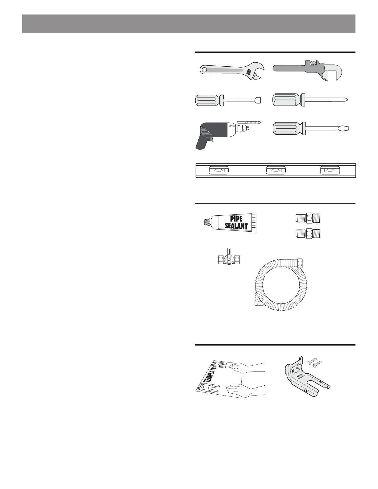
Tools you will need
(Wear safety glasses when using tools):
For leveling legs and Anti-Tip Bracket:
• Adjustable wrench or channel lock pliers (Fig. a)
• 5/16” Nutdriver or at head screwdriver (Fig. b)
• Electric drill & 1/8” drill bit (3/16” Masonry drill bit if
installing in concrete) (Fig. c)
• Level (Fig. d)
For gas supply connection:
• Adjustable wrench and pipe wrench (Figs. a & e)
For burner ame adjustment:
• Phillips head and small at-blade screwdrivers (Figs. f
& g)
Materials you will need:
• Pipe joint sealant that resists action of LP/Propane gas
(Fig. h)
• Gas line manual shut-o valve (Fig. i)
• A new exible metal appliance conduit (1/2” NPT x
3/4” or 1/2” I.D.) must be design certied by CSA
International. Because solid pipe restricts moving the
range, we recommend using a new exible conduit
(4 to 5 foot length) for each new installation and
additional reinstallations. (Fig. j)
• Use new are union adapters (1/2” NPT x 3/4” or 1/2”
I.D.) (Fig. k)
Tools
Fig. a
Fig. b
Materials
Fig. e
Fig. f
Fig. g
Fig. c
Fig. d
Fig. h
Fig. k
Materials supplied with appliance:
• Anti-Tip Template (Fig. l)
• Anti-Tip bracket; includes 2 mounting screws (Fig. m)
Fig. i
Fig. j
Materials supplied with appliance
Fig. l
Fig. m
3
Page 4
INSTALLATION INSTRUCTIONS - FREESTANDING GAS RANGE
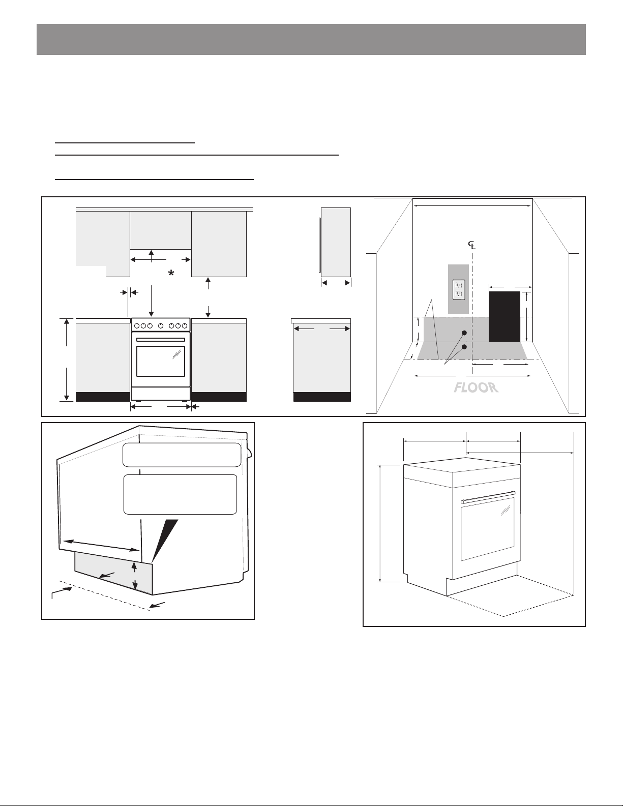
All dimensions for electrical outlet location
are maximum.
Shaded area
shows where the electrical outlet must be
installed
for flush to the wall installation.
Wall
Edge
3-3/4” (9.5 cm)
10”
(25 cm)
24”
(61 cm)
FRONT
VIEW
SIDE
VIEW
36”
(92 cm)
24”
(61 cm)
18”
(46 cm)
Minimum to
cabinets on
either side of
range.
13”
33 cm
Maximum depth
for cabinets
above range top.
24”
(61 cm)
25”
64 cm
30”
(76 cm)
Minimum
Minimum to wall
on either side of
range above
counter / cooktop.
6”
(15.2 cm)
0” (0 mm) clearance at sides and rear of range.
INSTALLATION AND SERVICE MUST BE PERFORMED BY A QUALIFIED INSTALLER.
IMPORTANT: SAVE FOR LOCAL ELECTRICAL INSPECTOR'S USE.
READ AND SAVE THESE INSTRUCTIONS FOR FUTURE REFERENCE.
Clearances and Dimensions
1. Provide adequate clearances between the range and adjacent combustible surfaces.
2. Location—Check location where the range will be installed. Check for proper electrical supply, and the stability
of the oor.
3. Dimensions that are shown must be used. Given dimensions provide minimum clearance. Contact surface must
be solid and level.
WALL
CABINET
OR
11”
WALL
OR
Open space
for gas
9”
10”
This space
must
remain clear
CABINET
*30" (762 mm) MINIMUM CLEARANCE BETWEEN THE TOP OF THE COOKING SURFACE AND THE BOTTOM OF AN UNPROTECTED
WOOD OR METAL CABINET; OR 24" (610 mm) MINIMUM WHEN BOTTOM OF WOOD OR METAL CABINET IS PROTECTED BY NOT
LESS THAN 1/4" (6 mm) FLAME RETARDANT MILLBOARD COVERED WITH NOT LESS THAN NO. 28 MSG SHEET STEEL, 0.015"
(0.4 mm) STAINLESS STEEL, 0.024" (0.6 mm) ALUMINUM OR 0.020" (0.5 mm) COPPER. 0" (0 mm) CLEARANCE IS THE MINIMUM FOR
THE REAR OF THE RANGE. FOLLOW ALL DIMENSION REQUIREMENTS PROVIDED ABOVE TO PREVENT PROPERTY DAMAGE,
POTENTIAL FIRE HAZARD, AND INCORRECT COUNTERTOP AND CABINET CUTS.
TO ELIMINATE THE RISK OF BURNS OR FIRE BY REACHING OVER HEATED SURFACE UNITS, CABINET STORAGE SPACE
LOCATED ABOVE THE SURFACE UNITS SHOULD BE AVOIDED. IF CABINET STORAGE IS TO BE PROVIDED, THE RISK CAN
BE REDUCED BY INSTALLING A RANGE HOOD THAT PROJECTS HORIZONTALLY A MINIMUM OF 5" (127 mm) BEYOND THE
35”
35”
89 cm
89 cm
2”
Gas location
23.5”
60 cm
24”
12”
23-5/8”
60 cm
41.5”
105 cm
Maximum
door open
BOTTOM OF THE CABINETS.
4
Page 5
INSTALLATION INSTRUCTIONS - FREESTANDING GAS RANGE
(31.75mm)
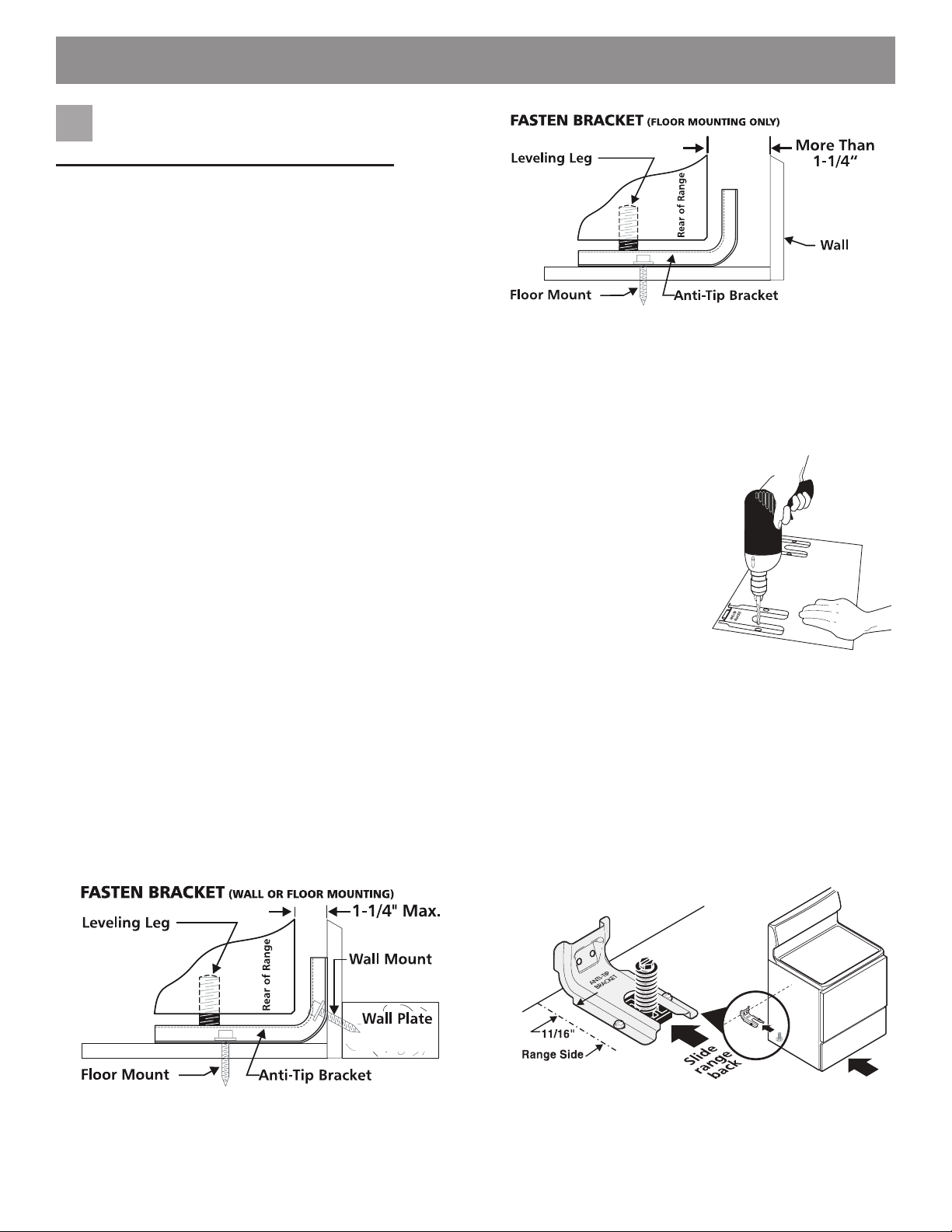
Install anti-tip bracket
1
IMPORTANT SAFETY WARNING!
To reduce the risk of tipping of the range, the range
must be secured to the oor by properly installed anti-tip bracket and screws packed with the range. Failure to install the anti-tip bracket will allow the range to
tip over if excessive weight is placed on an open door
or if a child climbs upon it. Serious injury might result
from spilled hot liquids or from the range itself.
If range is ever moved to a dierent location, the
anti-tip bracket must also be moved and installed with
the range.
Instructions are provided for installation in wood or
cement fastened to either the oor or wall. When
installed to the wall, make sure that screws completely
penetrate dry wall and are secured in wood or met-
al. When fastening to the oor or wall, be sure that
screws do not penetrate electrical wiring or plumbing.
Anti-tip bracket installation instructions
a. Locate the bracket using the template - (Bracket
may be positioned on either the left or right side of the
range. Refer to Figs. 4, 5, & 7 to position the bracket if
template is not available).
Mark the oor or wall where left or right side of the
range will be located. If rear of range is against wall
or no further than 1-1/4” from wall when installed, you
may use the wall or oor mount method. If molding
is installed and does not allow the bracket to t ush
against wall, remove molding or mount bracket to oor.
For wall mount (Fig. 4), locate the bracket by placing
the back edge of the template against rear wall
and the side edge of template on the mark made
referencing the side of the range. Place bracket on
top of template and mark location of the screw holes
in wall. If rear of range is further than 1-1/4” from wall
when installed, attach bracket to the oor (See Fig. 5).
(31.75mm)
Fig. 5
For oor mount, locate the bracket by placing back
edge of the template where the rear of the range will
be located. Mark the location of the screw holes shown
in template.
b. Drill pilot holes & fasten bracket - Drill 1/8” pilot hole
where screws are to be located (Fig. 6). If bracket is to
be mounted to the wall, drill
pilot hole at an approximate
20° downward angle. If
bracket is to be mounted to
masonry or ceramic oors,
drill 3/16” pilot hole 1-3/4”
deep. The screws provided
may be used in wood or
concrete material. Use
5/16” nut-driver or at head
screwdriver to secure the
bracket in place.
c. Level & position range - Level range by adjusting the
(4) leveling legs with a wrench.
Note: A min. clearance of 1/8” is required between bottom
of range and leveling legs to allow room for bracket.
Slide range back into position (Fig. 7). Remove lower
panel or storage drawer to visually check that rear
leveling leg is inserted into and fully secured by the
bracket. For models with a warmer drawer or broiler
compartment, grasp the top rear edge of the range
and carefully attempt to tilt it forward.
Fig. 6
Fig. 4
5
Fig. 7
Page 6
INSTALLATION INSTRUCTIONS - FREESTANDING GAS RANGE
Provide an adequate gas supply.
2
When shipped from the factory, this unit is designt to
operate on 4” (10,16 cm) water column (1,0 kPa) natural
gas manifold pressure. A convertible pressure regulator is
connected to the range manifold and must be connected
in series with the gas supply line. If an LP/Propane conversion kit has been used, follow the instructions provided
with the kit for converting the pressure regulator to LP/
Propane use.
Please note: Operation at elevations above 2000 ft.,
appliance rating shall be reduced at the rate of 4 percent
for each 1000 ft. above sea level.
Care must be taken during installation of range not to
obstruct the ow of combustion and ventilation air.
For proper operation, the maximum inlet pressure to the
regulator should be no more than 14 inches of water
column pressure. The inlet pressure to the regulator must
be at least 1 inch greater than regulator manifold pressure.
Example: If regulator is set for natural gas 4 inch manifold
pressure, inlet pressure must be at least 5 inches; if
regulator has been converted for LP/Propane gas 10
inch manifold pressure, inlet pressure must be at least 11
inches.
Leak testing of the appliance shall be conducted according
to the instructions in step 4g.
The gas supply line should be 1/2” or 3/4” I.D.
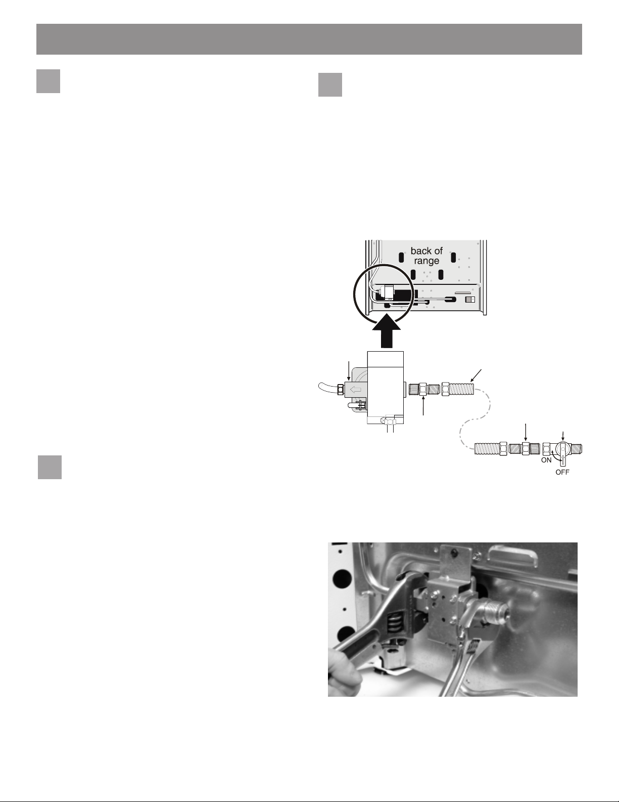
Connect range to gas supply.
4
Note: To prevent leaks use pipe joint sealant on all male
(outside) pipe threads. Do not allow gas pressure
regulator to turn on pipe when tightening ttings.
a. Install an external manual gas shut-o valve to gas
supply line in an accessible location outside of range.
Be sure you know where and how to shut o the gas
supply to the range (See Fig. 8).
b. Install 1/2” are union adapter to gas pressure
regulator using no more than 15ft./lbs. of torque
(Refer to Fig. 8).
Pressure
regulator
Flare
union
adaptor
Flexible appliance
conduit
Flare
union
adaptor
Manual
shut-o
valve
3
Seal wall openings.
Seal any openings in the wall behind the range and in the
oor under the range after gas supply line is installed.
Fig. 8 - gas supply connections
Be sure to stabilize the left side of the gas pressure
regulator before tightening ANY ttings to the pressure
regulator. Do not allow pressure regulator to turn on
pipe when tightening ttings (Refer to Fig. 9).
Fig. 9
6
Page 7
INSTALLATION INSTRUCTIONS - FREESTANDING GAS RANGE
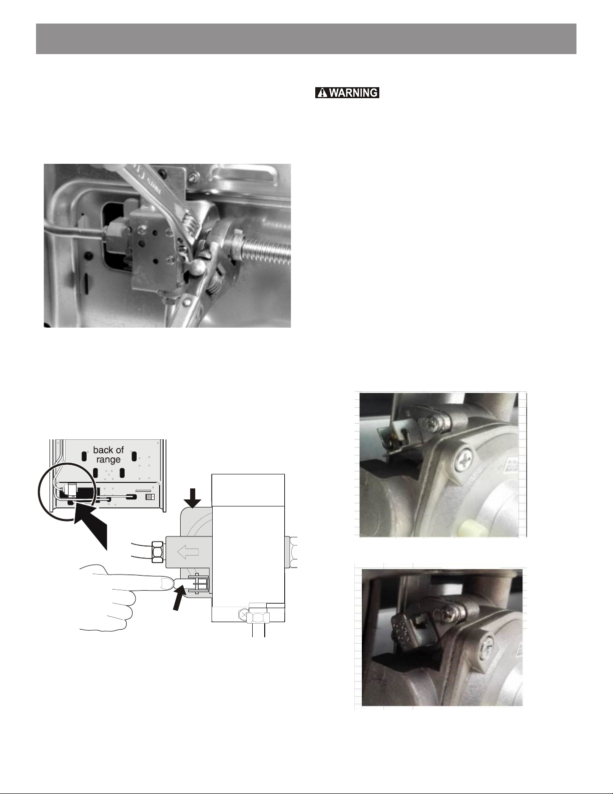
c. Tighten the gas supply tting and/or appliance conduit
to are union adaptor on the right side of the pressure
regulator (refer to Fig. 10) using NO MORE THAN
15ft./lbs. of torque. Be sure to stabilize the 1/2”
are union adapter with an adjustable wrench before
tightening the gas supply tting and/or appliance
conduit.
Fig. 10
d. Install are union adapter to external manual shut-o
valve (See Fig. 8).
e. Attach exible appliance conduit to are union adaptor
on shut-o valve (See Fig. 8).
f. Make sure the service shut-o valve on pressure
regulator is set to the ON position (See Fig. 11).
Checking manifold gas pressure
Do not use ame to check for gas leaks.
Disconnect the range and its individual shut-o valve from
the gas supply piping system during any pressure testing
of that system at test pressures greater than 14” of water
column pressure (approximately 1/2” psig).
The appliance must be isolated from the gas supply piping
system by closing its individual manual shut-o valve during
any pressure testing of the gas supply piping system at
test pressures equal to or less than 14” of water column
pressure (approximately 1/2” psig).
If it should be necessary to check the manifold gas
pressure, connect manometer (water gauge) or other
pressure device to the top burner right rear orice. Using a
rubber hose with inside diameter of approximately 1/4,” hold
tubing down tight over orice. Turn burner valve on.
For an accurate pressure check have at least two (2) other
top burners burning. Be sure the gas supply (inlet) pressure
is at least one inch above specied range manifold
pressure. The gas supply pressure should never be over
14” water column. When properly adjusted for Natural
Gas the manifold pressure is 4”. For LP/Propane Gas the
manifold pressure is 10”.
Pressure
regulator
Service shut-o
valve (shown in
ON position)
Fig. 11
g. Check for gas leaks. Turn the gas supply on to the
range and use a liquid leak detector at all joints and
conduits to check for leaks in the system.
Fig. 11a: Open shut-o valve
Fig. 11b: Closed shut-o valve
7
Page 8
INSTALLATION INSTRUCTIONS - FREESTANDING GAS RANGE
Read the following electrical
5 6
connection details before
connecting electricity to range.
Before servicing, disconnect electrical
supply at circuit breaker, fuse or power cord.
Electric requirements:
A dedicated, properly grounded and polarized branch
circuit protected by a 15 amp. circuit breaker or time delay
fuse. See serial plate for proper voltage.
Extension cord precautions:
Because of potential safety hazards under certain
conditions, we strongly recommend against the use of any
extension cord.
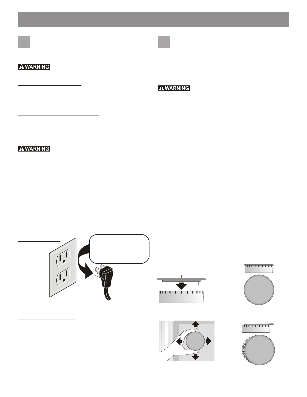
Please read carefully! For personal safe-
ty, this product must be properly grounded.
Do not, under any circumstances, cut or remove the third
(ground) prong from the power cord (See Fig. 12).
Where a standard two-prong wall receptacle is
encountered, it is the personal responsibility and obligation
of the customer to have it replaced with a properly grounded three-prong wall receptacle.
Preferred method
Grounding
type wall
receptacle
Do not, under any
circumstances, cut,
remove or bypass the
grounding prong.
Power
supply
cord with
3-prong
grounding
plug
Check burner cap placement.
It is very important to be sure that all surface burner caps
and burner grates are properly installed and in the correct
locations before operating the appliance. Please note that
the burner heads are secured to the cooktop. The cook-
top is not removeable. Do not attempt to remove or lift
the cooktop.
To prevent are-ups and avoid creation of
harmful by-products, do not use the cooktop without all
burner caps properly installed to insure proper ignition and
gas ame size.
Always keep the burner caps and burner heads in place
whenever the surface burners are in use. Do not allow
spills, food, cleaning agents or any other material to
enter the gas orice holder openings.
Check and be sure the size of each burner cap matches
the size of the burner head. Check and be sure that all
round style burner caps are correctly in place on round
burner heads.
Check and be sure that all oval style burner caps are cor-
rectly in place on oval burner heads (if equipped). Check
and be sure that all dual or twin style burner caps are cor-
rectly in place on dual or twin burner heads (if equipped).
On round style burners, the burner cap lip (See Fig. 13)
should t snug into the center of burner head and be level.
Refer to Figs. 14 & 15 for correct and incorrect burner cap
placement.
Once in place, you may check the t by gently sliding
the burner cap from side to side (Fig. 16) to be sure it
is centered and rmly seated. When the burner cap lip
makes contact inside the center of the burner head you will
be able to hear the burner cap click. Please note that the
burner cap should NOT move o the center of the burner
head when sliding from side to side.
Burner cap
Burner cap lip
Fig. 12
Grounding instructions:
The power cord of this appliance is equipped with a
3-prong (grounding) plug which mates with a standard
3-prong grounding wall receptacle to minimize the
possibility of electric shock hazard from this appliance.
The customer should have the wall receptacle and circuit
checked by a qualied electrician to make sure the
receptacle is properly grounded and polarized.
Fig. 13
Fig. 16
8
Correct burner cap placement
Fig. 14
Incorrect burner cap placement
Fig. 15
Page 9
INSTALLATION INSTRUCTIONS - FREESTANDING GAS RANGE
Check ignition of surface
7
burners.
Operation of electric igniters should be checked after
range and supply line connectors have been carefully
checked for leaks and range has been connected to electric power.
a. To check for proper ignition, push in and turn a
surface burner knob counterclockwise to the LITE
position. You will hear the igniter sparking.
b. The surface burner should ignite when gas is available
to the burner. Purge air from supply lines by leaving
knob in the LITE position until burner ignites. Each
burner should light within four (4) seconds in normal
operation after air has been purged from supply lines.
c. Visually check that burner has a ame. Once the
burner ignites, the control knob should be turned out of
the LITE position.
d. Try each surface control knob separately until all
surface burners have been checked. Each burner
location is equipped with a separate electrode.
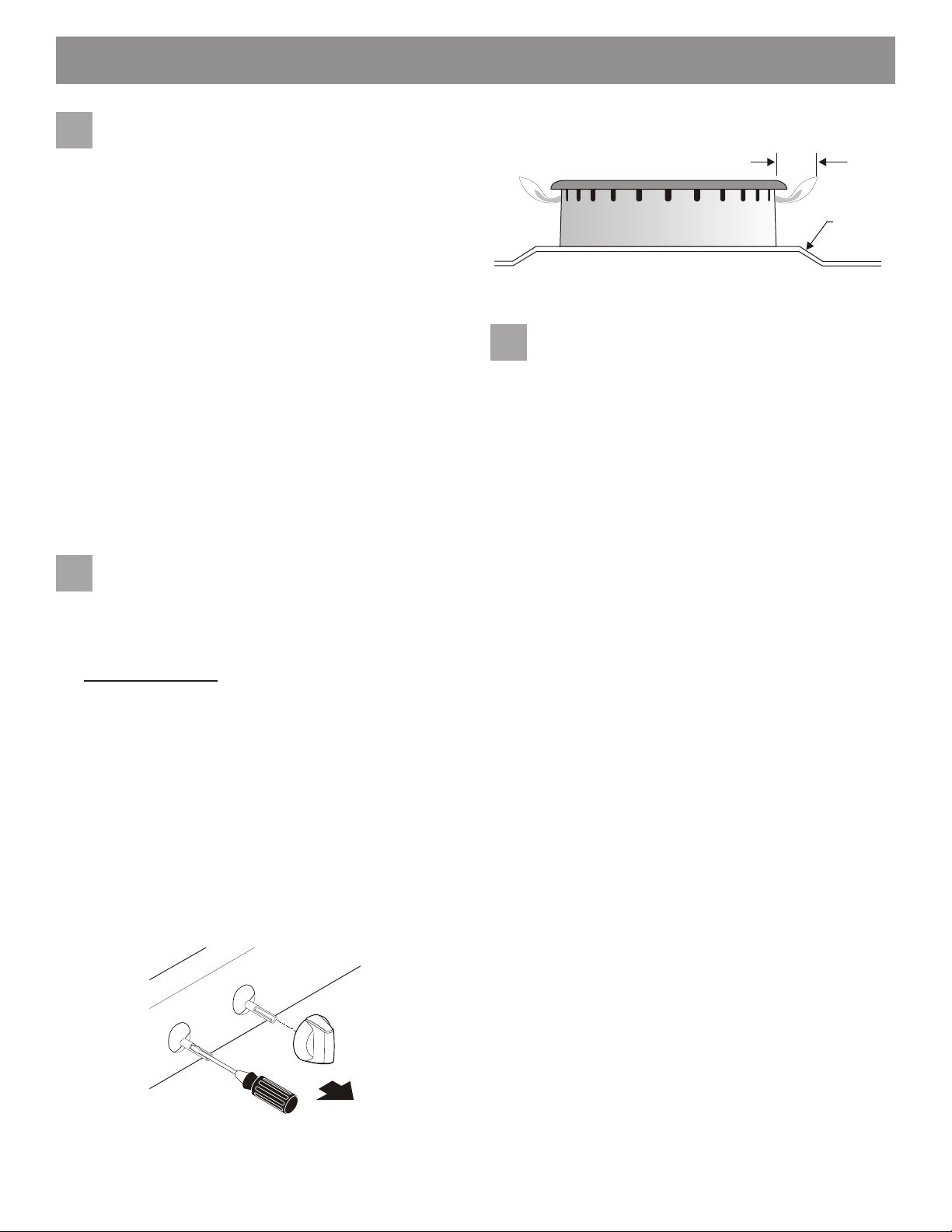
Adjust LOW setting of surface
8
burner valves (linear ow).
Test to verify if LOW setting should be adjusted:
a. Push in and turn control to LITE until burner ignites.
b. Push in and quickly turn knob to lowest position.
c. If burner goes out, reset control to OFF.
d. Remove the surface burner control knob.
e. Insert a thin-bladed screwdriver into the hollow valve
stem and engage the slotted screw inside. Flame size
can be increased or decreased with the turn of the
screw (see Fig. 17 amd Fig. 18).
f. Adjust ame until you can quickly turn knob from
LITE to lowest position without extinguishing the
ame. Flame should be as small as possible without
extinguishing.
Note: Air mixture adjustments are not required on surface
burners.
Burner ame size
Fig. 18
Check ignition of oven burners.
9
The operation of oven igniters should be checked after
range and supply line connectors have been carefully
checked for leaks and range has been connected to
electric power. Be sure all packing materials and literature are removed from oven.
The oven burner is equipped with an electric control system as well as an electric oven burner igniter. If your model
is equipped with an upper oven burner, it will also have
an electric burner igniter. These control systems require
no adjustment. When the oven is set to operate, current
will ow to the igniter. It will “glow” similar to a light bulb.
When the igniter has reached a temperature sucient to
ignite gas, the electrically controlled oven valve will open
and ame will appear at the oven burner. There is a time
lapse from 30 to 60 seconds after the thermostat is turned
ON before the ame appears at the oven burner. When the
oven reaches the set temperature, the glowing igniter will
cycle o. The burner ame will turn o in 20 to 30 seconds
after the igniter turns o. To maintain any set oven
temperature, this cycle will continue as long as the oven
control is set to operate.
To check oven burner ignition:
a. Set oven to Bake at 300ºF. See User’s Manual for
operating instructions.
b. Within 60 seconds the oven burner should ignite.
Check for proper ame, and allow the burner to cycle
once. Reset control to OFF.
c. If your model is equipped with a waist-high broiler,
set oven to Broil. See User’s Manual for operating
instructions.
d. Within 60 seconds the broil burner should ignite.
Check for proper ame. Reset control to OFF.
5/8”
Cooktop
Fig. 17
9
Page 10
INSTALLATION INSTRUCTIONS - FREESTANDING GAS RANGE
Make sure range is level.
11
Level the range by placing a level horizontally on an oven
rack. Check diagonally from front to back, then level the
range by either adjusting the leveling legs or by placing
shims under the corners of the range as needed.
Note: After installation is complete, make sure all controls
are left in the o position.
Care, cleaning and maintenance
Refer to the User’s manual for detailed cleaning
instructions. If removing the range is necessary for
cleaning or maintenance, shut o gas supply. Disconnect
the gas and electrical supply. If the gas or electrical supply
is inaccessible, lift the range slightly at the front and pull
out away from the wall. Pull out only as far as necessary to
disconnect the gas and electrical supply. Finish removing
the range for servicing and cleaning. Reinstall in reverse
order making sure to level the range and check gas
connections for leaks. Be sure to read and follow step 1 for
proper Anti-tip installation.
Before you call for service
Read the “Before You Call” and operating instruction
sections in your Use & Care Guide. It may save you time
and expense. The list includes common occurrences that
are not the result of defective workmanship or materials in
this appliance.
Refer to the warranty in your Use & Care Guide for our
toll-free service number and address. Please call or write
if you have inquiries about your range product and/or need
to order parts.
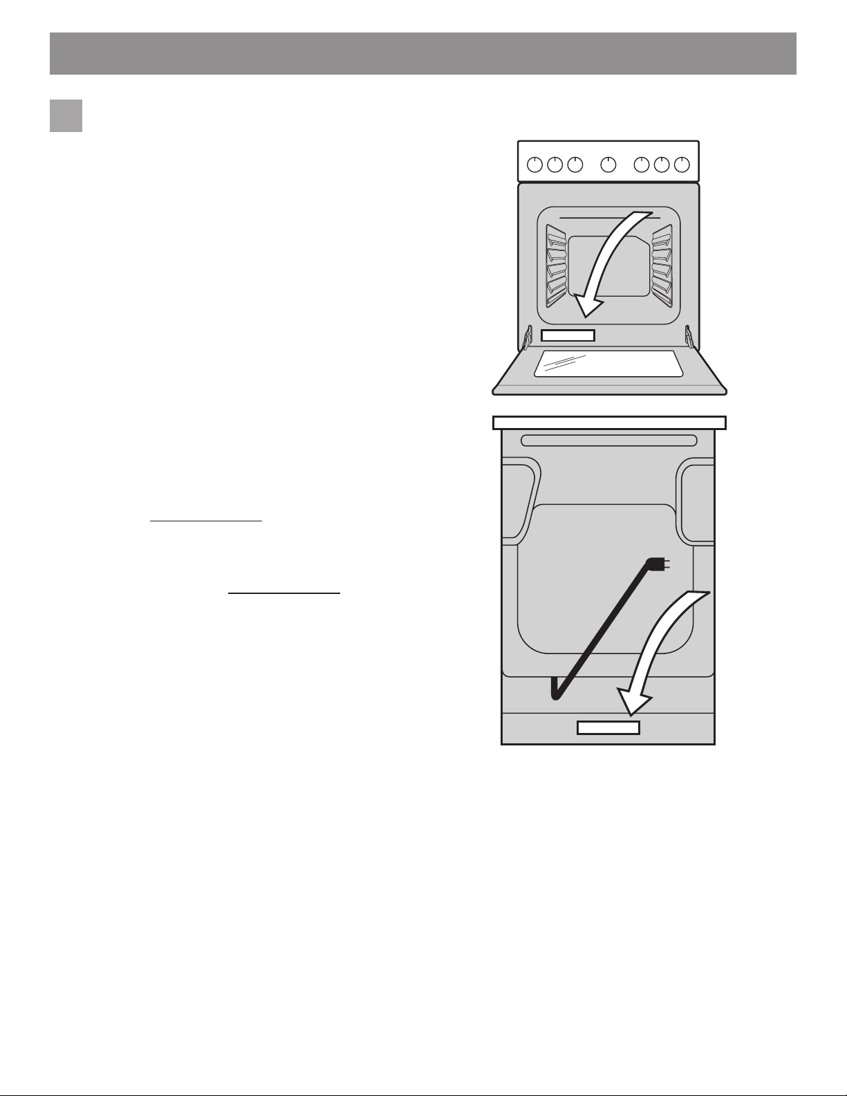
Model and serial number location
The identication plate is located inside the oven door on
the lower left and the middle-bottom of the back of the
appliance (Fig. 19).
When ordering parts for or making inquires about your
range, always be sure to include the model and serial
numbers and a lot number or letter from the identication
plate on your range. Your identication plate also tells you
the rating of the burners, the type of fuel and the pressure
the range was adjusted for when it left the factory.
Fig. 19
10
Page 11
INSTRUCCIONES DE INSTALACIÓN - ESTUFA A GAS
LA INSTALACIÓN Y EL SERVICIO DEBEN SER EFECTUADOS POR UN INSTALADOR CALIFICADO.
IMPORTANTE: GUARDE ESTAS INSTRUCCIONES PARA USO DEL INSPECTOR LOCAL DE
ELECTRICIDAD. LEA Y GUARDE ESTAS INSTRUCCIONES PARA REFERENCIA FUTURA.
Riesgo de
volcamiento
• Un niño o un adulto puede volcar el
electrodoméstico y matarse.
• Compruebe que el dispositivo se
ha instalado en la pared o el suelo.
• Asegúrese de que al desplazar el
electrodoméstico, el dispositivo antivuelco queda bien
engarzado a la pared o el suelo.
• No utilice el electrodoméstico si este no dispone de
un dispositivo antivuelco bien colocado.
• No respetar estas instrucciones puede derivar en la
muerte o en quemaduras graves en niños y adultos.
Pata para
nivelar la
estufa
montura
antivuelco
Refer to your serial plate for applicable agency
certications
Proporcionar el tipo de combustible adecuado
Antes de continuar: su rango viene preajustado de
fábrica para operar con gas natural. Si se necesita la conversión de L.P., contacte a su proveedor local de L.P. Gas
para asistencia.
Se debe comprobar que se ha instalado correctamente
el soporte antivuelco. Para ello, utilice los dos
brazos para agarrar el borde de la parte posterior del
electrodoméstico. Con cuidado, trate de inclinar el
electrodoméstico hacia adelante. Si se ha instalado
correctamente, el electrodoméstico no debería inclinarse
hacia adelante.
Consulte las instrucciones de instalación
adecuadas del soporte antivuelco suministradas con
el electrodoméstico para garantizar una instalación
correcta.
Notas importantes para el instalador
• Lea todas las instrucciones antes de instalar la cocina.
• Retire todo material de empaquetado del horno y de
la gaveta de entibiado antes de conectar el suministro
eléctrico a la cocina.
• Observe todo código o reglamento.
• Asegúrese de dejar estas instrucciones con el
consumidor.
Nota importante para el consumidor
• Mantenga estas instrucciones con el manual del
usuario para futuras referencias.
• Be sure your range is installed and grounded properly
by a qualied installer or service technician.
Aparatos Instalados en el estado de Massachusetts:
Este Aparato sólo puede ser instalado en el estado de
Massachusetts por un plomero o ajustador de gas licenciado de Massachusetts. Este aparato se debe instalar
con un largo conector exible de gas de tres (3) pies/36
pulgadas. Una válvula manual de gas de tipo manija de
forma de “T” se debe instalar en la línea del suministro de
gas de este aparato.
1
809019203 Rev B (1901)
Page 12
INSTRUCCIONES DE INSTALACIÓN - ESTUFA A GAS
IMPORTANT SAFETY INSTRUCTIONS
• Instalación de esta estufa debe cumplir con todos los
códigos locales, o en ausencia de códigos locales con
el Código Nacional de Gas Combustible ANSI Z223.1/
NFPA .54—última edición o CAN/CGA-B149.1 and
CAN/CGA-B149.2 standards.
• Si la cocina se instala en una casa móvil (caravana),
la instalación deberá realizares de acuerdo a
los estándar de seguridad Manufactured Home
Construction and Safety Standard (Estándar de
seguridad y construcción de casa prefabricadas),
Título 24 CFR, Sección 3280 [anteriormente
denominada Federal Standard for Mobile Home
Construction and Safety (Estándar federal para
seguridad y construcción de casas prefabricadas),
Título 24, HUD (Sección 280)] o, en caso de que
dicho estándar no sea aplicable, deberá seguirse la
norma marcada por el Standard for Manufactured
Home Installations, ANSI/NCSBCS A225.1, o con
códigos locales.
• This range has been design certied by Underwriters
Laboratories (UL). As with any appliance using
gas and generating heat, there are certain safety
precautions you should follow. You will nd them in the
Use & Care Guide; read it carefully.
• Asegúrese de que la estufa sea instalada y conectada
a tierra en forma apropiada por un instalador calicado
o por un técnico.
• Esta estufa debe ser eléctricamente puesta a tierra
de acuerdo con los códigos locales, o en su ausencia,
con el Código Eléctrico Nacional ANSI/NFPA No. 70,
última edición en el Estados Unidos o por el estándar
de CSA, C22.1, Canadian Electrical Code, Part 1 en el
Canada. Vea las instrucciones para la puesta a tierra
página 8.
• Before installing the range in an area covered with
linoleum or any other synthetic oor covering, make
sure the oor covering can withstand heat at least
90°F above room temperature without shrinking,
warping or discoloring. Do not install the range over
carpeting unless you place an insulating pad or sheet
of 1/4-inch thick plywood between the range and
carpeting.
• Asegúrese de que el material que recubre las paredes
alrededor de la estufa, pueda resistir el calor generado
por la estufa.
• No obstruya el ujo del aire de combustión en la
ventilación del horno ni tampoco alrededor de la
base o debajo del panel inferior delantero de la
estufa. Evite tocar las aberturas o áreas cercanas
de la ventilación, ya que pueden estar muy calientes
durante el funcionamiento del horno. La estufa
requiere aire fresco para la combustión apropiada de
los quemadores.
• No se deben usar las cortinas de aire o cualquier otra
campana de ventilación superior que sople aire hacia
abajo sobre la estufa a gas a menos que la campana
de ventilación y la estufa hayan sido diseñadas,
probadas y certicadas por un laboratorio de pruebas
independiente para el uso combinado de la una con la
otra.
NO INTENTE ENCENDER EL HORNO
DE IGNICIÓN ELÉCTRICA DURANTE UN APAGÓN
DE LUZ. COLOQUE TODOS LOS CONTROLES EN LA
POSICIÓN DE “APAGADO” CUANDO SE PRODUZCAN
SITUACIONES DE ESTE TIPO.
El encendedor eléctrico, volverá a encenderse automáticamente al volver a conectarse el suministro de energía
eléctrica tras un apagón si se han dejado los controles en
la posición de “ENCENDIDO”.
Si se produce un apagón eléctrico cuando esté utilizando
la aplicación, los quemadores de supercie continuarán en
funcionamiento y podrá encenderlos con una cerilla.
Coloque una cerilla encendida al lado del quemador y, a
continuación, gire lentamente el mando hasta colocarlo en
a posición LITE de encendido. Extreme las precauciones
la encender el quemador de este modo.
Nunca deje niños solos o desatendidos en
un área donde un artefacto está siendo usado. A medida
que los niños crecen, enséñeles el uso apropiado y de
seguridad para todos los artefactos. Nunca deje la puerta
del horno abierta cuando la estufa está desatendida.
No se pare, apoye o siente en las puertas
o cajones de esta estufa pues puede resultar en serias
lesiones y puede también causar daño a la estufa.
• Be sure to keep the appliance clear of combustible
materials, gasoline, and other ammable vapors and
liquids.
• No almacene artículos que puedan interesar a los
niños en los gabinetes sobre la estufa. Los niños
pueden quemarse seriamente tratando de trepar a la
estufa para alcanzar estos artículos.
• Los gabinetes de almacenamiento sobre la estufa
deben ser evitados, para eliminar la necesidad de
tener que pasar sobre los quemadores superiores de
la estufa para llegar a ellos.
• Ajuste el tamaño de la llama de los quemadores
superiores de tal manera que ésta no sobrepase el
borde de los utensilios de cocinar. La llama excesiva
es peligrosa.
• No use el horno como espacio de almacenaje. Esto
creará una situación potencialmente peligrosa.
2
Page 13
INSTRUCCIONES DE INSTALACIÓN - ESTUFA A GAS
• Nunca use la estufa para calentar el cuarto. El uso
prolongado de la estufa sin la adecuada ventilación
puede resultar peligroso.
• No almacene ni utilice gasolina u otros vapores y
líquidos inamables en la proximidad de éste o de
cualquier otro artefacto eléctrico. Puede provocar
incendio o explosión.
• Ajuste todos los controles a la posición “OFF”
(apagada) después de haber hecho una operación
con tiempo programado.
• A diferencia de la gama estándar cocinas de gas,
ESTA PLANCHA DE COCINA NO ES MOVIBLE. No
intente quitar la plancha de cocina.
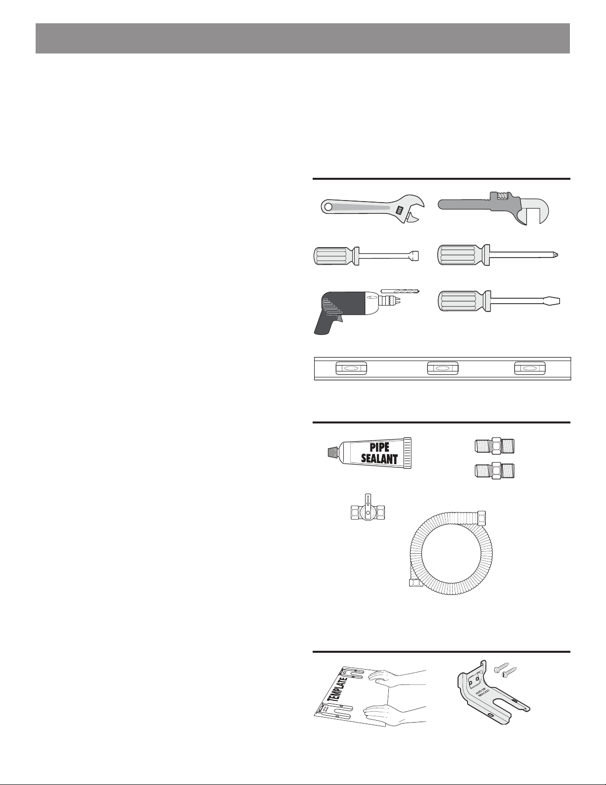
Herramientas que va a necesitar
(Use gafas de seguridad cuando use herramientas):
Para patas de nivelación y montura anti-vuelco:
• Llave ajustable o alicates (Fig. a)
• Llave para apretar tuercas de 5/16” o un destornillador
de cabeza planar (Fig. b)
• Taladro eléctrico y una broca de 1/8” (broca de taladro
de hormigón de 3/16” si se instala sobre hormigón
(Fig. c)
• Nivel (Fig. d)
Para la conexión al suministro de gas:
• Llave ajustable y llave de tubo (Figs. a & e)
Para el ajuste de la llama del quemador:
• Destornilladores de estrella y de cabeza plana (Figs. f
& g)
Material que va a necesitar:
• Sellador para uniones de tuberías que resista la
acción del gas propano/PL (Fig. h)
• Válvula de desconexión de la línea de gas (Fig. i)
• Un conducto de metal exible (½” NPT x ¾” o de
½” de D.I.) con diseño certicado por CSA Grupo.
Ya que las tuberías rígidas restringen el movimiento
de la cocina, se recomienda el uso de tuberías
exibles nuevas (de entre 1,20 a 1,50 mts) durante la
instalación y cada vez que se vaya a instalar de nuevo
o se cambie de lugar posteriormente. (Fig. j)
• Utilice siempre los adaptadores de campana (½” NPT
x ¾” o de ½” D.I.) (Fig. k)
Materiales suministrados con el dispositivo:
• Plantilla Anti-Tip (Fig. l)
• Soporte antivuelco; incluye 2 tornillos de montaje
(Fig. m)
Herramientas
Fig. a
Fig. b
Fig. c
Fig. d
Fig. e
Fig. f
Fig. g
Materiales
Fig. h
Fig. k
Fig. i
Fig. j
Materiales suministrados con el
electrodoméstico
Fig. l
3
Fig. m
Page 14
INSTRUCCIONES DE INSTALACIÓN - ESTUFA A GAS
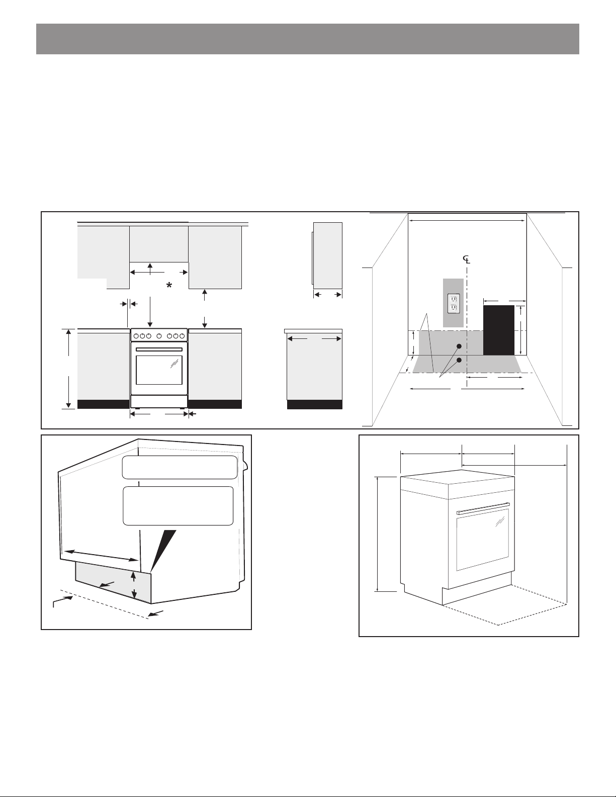
All dimensions for electrical outlet location
are maximum.
Shaded area
shows where the electrical outlet must be
installed
for flush to the wall installation.
Wall
Edge
3-3/4” (9.5 cm)
10”
(25 cm)
24”
(61 cm)
VISTA
FRONTAL
VISTA
LATERAL
36”
(92 cm)
24”
(61 cm)
18”
(46 cm)
Minimo para
gabinetes a
cada lado del
rango.
13”
33 cm
Profundidad maxima
para gabinetes arriba
del rango superior
24”
(61 cm)
25”
64 cm
30”
(76 cm)
Minimum
Mínimo a la pared
a cada lado del
rango sobre el
mostrador / la
estufa
6”
(15.2 cm)
0” (0 mm) espacio libre en los laterales y en la parte
trasera del rango
LA INSTALACIÓN Y EL SERVICIO DEBEN SER EFECTUADOS POR UN INSTALADOR
CALIFICADO. IMPORTANTE: GUARDE ESTAS INSTRUCCIONES PARA USO DEL INSPECTOR
LOCAL DE ELECTRICIDAD. LEA Y GUARDE ESTAS INSTRUCCIONES PARA REFERENCIA
FUTURA.
Clearances and Dimensions
1. Provea espacios libres adecuados entre la estufa y las supercies combustibles adyacentes.
2. Ubicación – Revise el lugar donde será instalada la estufa. Verique el suministro de energía eléctrica y la
estabilidad del piso.
3. Es esencial que se usen las dimensiones que se muestran. Las dimensiones indicadas proveen los espacios
libres mínimos. La supercie de contacto debe ser rme y nivelada.
PARED
GABINETE
Espacio abierto
O
PARED
9”
GABINETE
2”
para el gas
Ubicación de gas
24”
PISO
10”
Este espacio
debe
permanecer
claro
12”
O
11”
23.5”
60 cm
35”
35”
89 cm
89 cm
Un mínimo de 36” de espacio entre la parte superior de la supercie para estufa y el fondo no protegido de un gabinete de metal o madera;
o un mínimo de 24” cuando el fondo de metal o madera del gabinete esta protegido por no menos de ¼” de material retardante, con una
hoja de acero de no menos MSG No.28, 0.015” de acero inoxidable, 0.024” de aluminio o 0.020” de cobre. 0” es el espacio mínimo para
la parte trasera de la estufa. Siga todos los requerimientos de medidas antes proporcionados para evitar daños a la propiedad: peligro
de encendidos potenciales o supercies y cortes de gabinetes que sean incorrectos.
Para eliminar el riesgo de quemaduras o incendio cuando trate de alcanzar objetos por sobre unidades de supercie calentadas,
debe evitarse que los gabinetes para almacenamiento están localizados encima de la supercie de la estufa. Si existen gabinetes
de almacenamiento, el riesgo puede ser reducido instalando una campana de estufa que se proyecte en forma horizontal a una
23-5/8”
60 cm
41.5”
105 cm
Puerta
maxima
abierta
distancia mínima de 5” mas ala del fondo de los gabinetes.
4
Page 15
INSTRUCCIONES DE INSTALACIÓN - ESTUFA A GAS
(31.75mm)
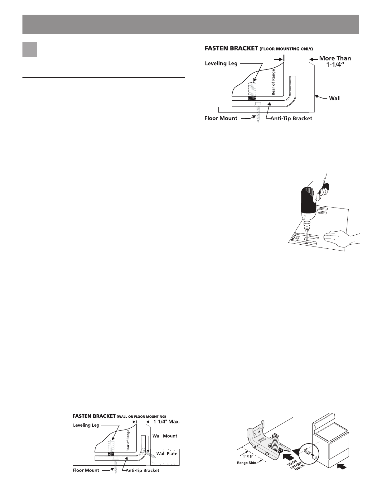
Instrucción para la instalación
1
del braquete anti-basculante
NOTA IMPORTANTE DE SEGURIDAD!
Para reducir el riesgo de inclinación de la cocina, ésta
debe ser asegurada hacia el piso con las jaciones
de anti-inclinación y los tornillos que vienen con la
cocina. Si no instala las jaciones, corre el riesgo que
su cocina pueda inclinarse si pone demasiado peso
sobre la puerta abierta o si un niño sube sobre ésta.
Esto podría ocasionar graves causadas por derrames
de líquidos calientes o por la propria cocina.
Si la cocina es trasladada a otro lugar, las jaciones
de anti-inclinación deben también ser trasladadas y
instaladas con la cocina.
Las instrucciones son adecuadas para la instalación
en pisos de madera o cemento sujeto ya sea en el
piso o en la pared. Cuando se instala en la pared,
asegúrese de que los tornillos penetren completamente en la misma y que estén asegurados en madera
o metal. Cuando se asegura al piso o en la pared,
asegúrese de que los tornillos no penetren ningún
cableado eléctrico o plomería.
Anti-tip bracket installation instructions
a. Ubicación del soporte utilizando la plantilla - (El
soporte puede ser ubicado ya sea en el lado izquierdo
o derecho de la estufa. Refer to Figs. 4, 5, & 7 to
position the bracket if template is not available).
Marque el piso o la pared donde se colocará el
costado izquierdo o derecho de la estufa. Si la parte
trasera de la estufa será colocada contra la pared
o a no más de 1-1/4” de la pared cuando ya esté
instalada, usted puede usar el método de instalación
en el piso o en la pared. Si tiene moldura instalada y
ésta no permite que el soporte quede a ras contra la
pared, retire la moldura o instale el soporte en el piso.
Para el montaje en la pared (Fig. 4), ubique la plantilla
colocando el borde trasero de la plantilla contra la
pared trasera y el borde lateral de la plantilla en
la marca hecha indicando el costado de la estufa.
Coloque el soporte sobre la plantilla y marque la
ubicación de los agujeros de los tornillos en la pared.
Si la parte trasera de la estufa está a más de 1-1/4” de
la pared cuando ya está instalada, instale el soporte
en el piso. (See Fig. 5).
(31.75mm)
Fig. 5
Para el montaje en el piso, ubique el soporte
colocando el borde trasero de la plantilla donde
quedará ubicada la parte trasera de la estufa. Marque
la ubicación de los agujeros de los tornillos mostrados
en la plantilla..
b. Taladre agujeros pilotos e instale el soporte -
Taladre un agujero piloto
de 1/8” donde se vayan
a instalar los tornillos.
Si el soporte va a ser
instalado en la pared,
taladre un agujero piloto
en un ángulo descente de
aproximadamente 20° Si el
soporte va a ser instalado en
pisos de mampostería o de
cerámica, taladre un agujero
piloto de 3/16” y 1-3/4” de
profundidad. Los tornillos provistos pueden ser usados
en materiales de madera o concreto. Use una llave
de tuerca de 5/16” o un destornillador de punta plana
para asegurar el soporte en su lugar.
c. Nivele y ubique la estufa - Nivele la estufa ajustando
los cuatro (4) tornillos niveladores con una llave.
Nota: Se debe dejar un espacio libre mínimo de
1/8” entre la parte inferior de la estufa y los tornillos
niveladores a n de dejar espacio para instalar el
soporte.
Deslice la estufa de nuevo a su lugar (Fig. 7).
Verique visualmente si el tornillo nivelador trasero
está insertado y rmemente asegurado por el soporte
antivuelco retirando el panel inferior o la gaveta de
almacenamiento. Para los modelos con una gaveta
calentadora o compartimiento asador, sujete la estufa
desde el borde superior trasero y trate de inclinarla
hacia adelante cuidadosamente.
Fig. 6
Fig. 4
Fig. 7
5
Page 16
INSTRUCCIONES DE INSTALACIÓN - ESTUFA A GAS
Proporcione un suministro de
2
gas adecuado.
Cuándo se envía de la fábrica, esta unidad ha sido ajustada para operar con un múltiple de admisión para gas natural de 4”. Un regulador de presión convertible esta conectado a la válvula distribuidora y DEBE ser conectado con
la tubería del suministro de gas. Si el juego de conversión
del propano LP/Propano se ha utilizado, sigue las instrucciones proporcionadas el juego para convertir el regulador
de presión al uso de LP/Propano.
Tenga en cuenta: la operación en elevaciones superiores
a 2000 ft., La clasicación del artefacto se reducirá a razón
del 4 por ciento por cada 1000 pies sobre el nivel del mar.
Se debe de tener cuidado durante la instalación de la
estufa para no obstruir el ujo de aire de combustión y
ventilación.
Para la operación apropiada, la máxima presión de
entrada al regulador no debe exceder la presión de
una columna de agua de 14”. La presión de entrada al
regulador debe ser por lo menos 1” más grande que la
válvula distribuidora.
Ejemplos: Si regulador se pone para el gas natural con
una presión de 4”, la presión de entrada al regulador debe
ser por lo menos 5”; si el regulador se ha convertido para
gas LP/Propano 10” la presión de entrada al regulador
debe ser por lo menos 11”.
Un examen de detección de fugas del aparato debe ser
realizado según las instrucciones en el paso 4.
La línea de fuente de gas debe ser de ½” o de ¾”.
Conecte la estufa al suministro
4
de gas.
Nota: Para evitar fugas, use sellador para juntas de
tuberías en todas las roscas de tubería macho (exterior). No permita que el regulador de presión de gas
encienda la tubería cuando apriete los accesorios.
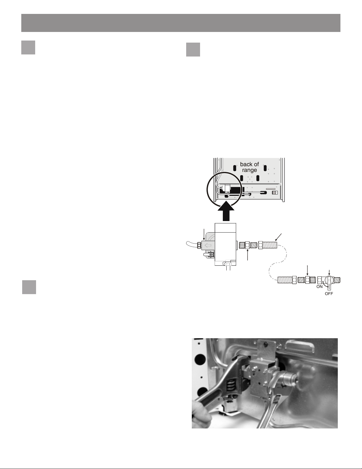
a. Instale una válvula manual externa para cierre de
gas hacia la línea de suministro de gas que tenga
una ubicación de fácil acceso fuera de la cocina.
Asegúrese de conocer dónde y cómo se cierra el
suministro de gas hacia la cocina (Vea Fig. 8).
b. Instale un adaptador para unión de campana de ½”
hacia el válvula manual del unidad usado NO MAS DE
15pies/lbs de torque. (Vea Fig. 8).
Pressure
regulator
Flare
union
adaptor
Flexible appliance
conduit
Flare
union
adaptor
Manual
shut-o
valve
3
Selle las aperturas.
Selle todas las aberturas en el suelo debajo
del electrodoméstico o en la pared detrás del
electrodoméstico después de haber instalado la tubería de
suministro de gas.
Fig. 8 - gas supply connections
Asegúrese de estabilizar el lado izquierdo del
regulador de presión de gas antes de ajustar
CUALQUIER accesorio al regulador de presión. No
permita que el regulador de presión encienda el tubo
al apretar los accesorios (Vea Fig 9).
Fig. 9
6
Page 17
INSTRUCCIONES DE INSTALACIÓN - ESTUFA A GAS
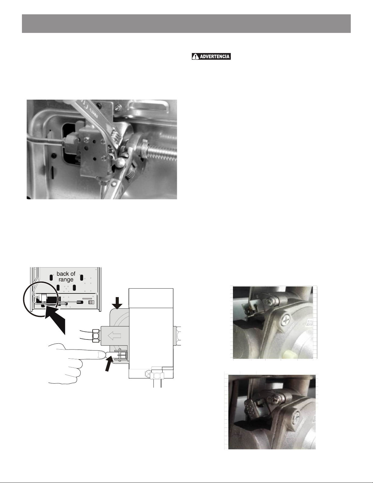
c. Apretar el conector exible de gas y/o el conducto del
electrodoméstico para unir con la válvula manual de
la unidad usando NO MAS DE 15 pies/lbs de troqué.
Asegurar estabilización del adaptador para unión
de campana de 1/2” y ajustar con la pinza antes de
apretar conector exible de gas y/o conducto del
electrodoméstico. (Vea Fig. 10)
Fig. 10
d. Instale el adaptador de la unión de campana hacia la
válvula manual externa de cierre (Vea Fig. 8).
e. Conecte el exible conducto a la unión de campana en
la válvula manual externa de cierre (Vea Fig. 8).
f. Asegúrese de que la válvula de cierre del servicio
en el regulador de presión esté en la posición ON
(Fig. 11).
Pressure
regulator
Revisión de la presión de gas en el colector
No use fuego para comprobar la
existencia de fugas de gas.
Desconecte la cocina y su válvula de cierre individual del
sistema de tubería del suministro de gas durante cualquier
prueba de presión de ese sistema para presiones de
prueba superiores a 14” de presión de columna de agua
(aproximadamente ½” psig).
La aplicación debe aislarse del sistema de la tubería de
suministro de gas cerrando su válvula de cierre manual
individual durante cualquier prueba de presión del sistema
de tubería de suministro de gas para presiones de prueba
iguales o mayores a 14” de presión de columna de agua
(aproximadamente ½” psig).
Si fuera necesario revisar la presión de gas en el colector,
conecte el manómetro (medidor de agua) u otro dispositivo
de presión al oricio posterior derecho del quemador
superior. Usando una manguera de caucho con un
diámetro interior de aproximadamente ¼”, sostenga fuerte
la tubería hacia abajo sobre el oricio. Encienda la válvula
del quemador.
Para una revisión exacta de la presión, tenga por lo menos
otros dos (2) quemadores superiores. Asegúrese que
la presión del suministro de gas (entrada) se encuentra
por lo menos una pulgada por encima de la presión
especicada en el colector de la cocina. La presión del
suministro de gas nunca debe encontrarse por encima
de 14” de la columna de agua. Cuando se encuentra
debidamente ajustado para Gas Natural, la presión en
el colector es 4” (para PL/Gas Propano, la presión en el
colector es 10”).
Service shut-o
valve (shown in
ON position)
Fig. 11
g. Verique si existen fugas. Encienda el suministro de
gas hacia la cocina y use el detector de derrames
de líquidos en todas las uniones y conductos para
comprobar la existencia de fugas en el sistema.
Fig. 11a: Válvula de cierre abierto
Fig. 11b: Válvula de cierre cerrada
7
Page 18
INSTRUCCIONES DE INSTALACIÓN - ESTUFA A GAS
Lea los siguientes detalles de
5 6
conexión eléctrica antes de
conectar la electricidad al rango.
Antes de realizar el servicio, desconecte
el suministro eléctrico en el disyuntor, fusible o cable
de alimentación.
Requisitos eléctricos:
Un circuito derivado dedicado, correctamente conectado a
tierra y polarizado protegido por un amplicador de 15 amperios. disyuntor o fusible de retardo. Ver placa de serie
para voltaje apropiado.
Precauciones con el cable de extensión:
Debido a los peligros potenciales de seguridad bajo ciertos condiciones, recomendamos encarecidamente evitar el
uso de cualquier cable de extensión.
¡Por favor lea cuidadosamente! Por se-
guridad personal, este producto debe estar debidamente
conectado a tierra.
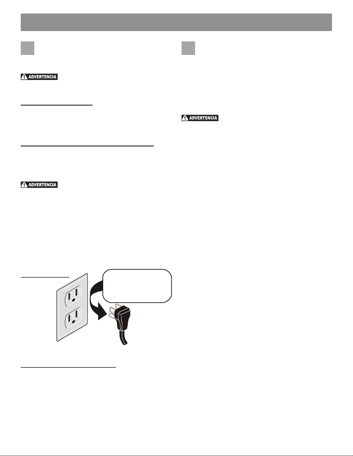
Bajo ninguna circunstancia, corte o retire la tercera punta
(tierra) del cable de alimentación (Fig. 12).
En lugares en los que aya un enchufe de pared estándar
de dos patillas, el cliente tendrá responsabilidad directa y
la obligación de reemplazarlo por un enchufe de pared de
tres patillas debidamente cableado a tierra.
Preferred method
Grounding
type wall
receptacle
Fig. 12
Instrucciones de conexión a tierra:
El cable de alimentación de este electrodoméstico está
equipado con un enchufe de 3 patas (conexión a tierra)
que se acopla con un tomacorriente de pared con toma
de tierra de 3 patas para minimizar la posibilidad de riesgo
de descarga eléctrica por este artefacto. El cliente debe
hacer que el tomacorriente de pared y el circuito sean
revisados por un electricista calicado para asegurarse de
que el receptáculo esté correctamente conectado a tierra y
polarizado.
Do not, under any
circumstances, cut,
remove or bypass the
grounding prong.
Power
supply
cord with
3-prong
grounding
plug
Verique la colocación de la tapa
del quemador.
Es muy importante asegurarse de que todas las tapas de
los quemadores de supercie y las rejillas de los quemadores estén instaladas correctamente y en las ubicaciones
correctas antes de operar el aparato. Tenga en cuenta
que las cabezas del quemador están aseguradas a la
supercie de cocción. La cubierta no es extraíble. No
intente quitar o levantar la supercie de cocción.
Para prevenir los brotes y evitar la
creación de subproductos dañinos, no use la cubierta sin
todas las tapas del quemador instaladas correctamente
para asegurar el encendido adecuado y el tamaño de la
llama del gas.
Siempre mantenga las tapas del quemador y las cabezas
del quemador en su lugar siempre que los quemadores de
supercie estén en uso. No permita que los derrames,
alimentos, agentes de limpieza o cualquier otro material entren en las aberturas del soporte del oricio de
gas.
Verique y asegúrese de que el tamaño de cada tapa
del quemador coincida con el tamaño de la cabeza del
quemador. Verique y asegúrese de que todas las tapas
del quemador de estilo redondo estén colocadas correctamente en las cabezas redondas de los quemadores.
Verique y asegúrese de que todas las tapas del quemador de estilo ovalado estén colocadas correctamente en
las cabezas de los quemadores ovales (si están instaladas). Verique y asegúrese de que todas las tapas de los
quemadores duales o gemelos estén colocadas correctamente en los cabezales de los quemadores duales o
gemelos (si corresponde).
En quemadores de estilo redondo, el labio de la tapa del
quemador (vea la Fig. 13) debe quedar ajustado en el centro de la cabeza del quemador y estar nivelado. Consulte
las Figs. 14 y 15 para la colocación correcta e incorrecta
de la tapa del quemador.
Una vez en su lugar, puede vericar el ajuste deslizando
suavemente la tapa del quemador de lado a lado (Fig.
16) para asegurarse de que esté centrada y rmemente
asentada. Cuando el labio de la tapa del quemador haga
contacto dentro del centro de la cabeza del quemador,
podrá escuchar el clic de la tapa del quemador. Tenga en
cuenta que la tapa del quemador NO debe moverse fuera
del centro de la cabeza del quemador cuando se deslice
de un lado a otro.
8
Page 19
INSTRUCCIONES DE INSTALACIÓN - ESTUFA A GAS
Vericar el encendido de la
7
supercie quemadores.
El funcionamiento de los encendedores eléctricos debe
vericarse después de que el alcance y los conectores de
la línea de suministro se hayan revisado cuidadosamente
para detectar fugas y el alcance se haya conectado a la
energía eléctrica.
a. Para vericar el encendido adecuado, empuje y
gire la perilla del quemador de supercie en sentido
antihorario a la posición LITE. Oirás el encendedor
chispeando.
b. El quemador de supercie debe encenderse cuando
haya gas disponible para el quemador. Purgue el aire
de las líneas de suministro dejando la perilla en la
posición LITE hasta que el quemador se encienda.
Cada quemador debe encenderse dentro de los cuatro
(4) segundos en funcionamiento normal después de
purgar el aire de las líneas de suministro.
c. Verique visualmente que el quemador tenga una
llama. Una vez que el quemador se enciende, la
perilla de control debe estar fuera de la posición LITE.
d. Pruebe cada botón de control de supercie por
separado hasta que se hayan vericado todos los
quemadores de supercie. Cada ubicación del
quemador está equipada con un electrodo separado.
Ajuste la conguración BAJA
8
de las válvulas del quemador de
supercie (ujo lineal).
Pruebe para vericar si la conguración BAJA debe
ajustarse:
a. Presione y gire el control a LITE hasta que el
quemador se encienda.
b. Presione y gire rápidamente la perilla a la posición
más baja.
c. Si el quemador se apaga, reinicie el control a OFF.
d. Retire la perilla de control del quemador de la
supercie.
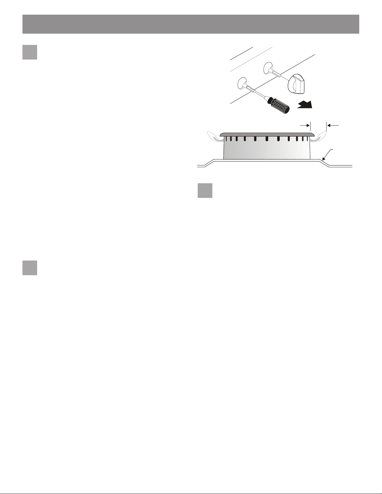
e. Inserte un destornillador de hoja delgada en el
vástago de la válvula hueca y enganche el tornillo
ranurado en el interior. El tamaño de la llama se puede
aumentar o disminuir con el giro del tornillo (consulte
la Fig. 17 y la Fig. 18).
f. Ajuste la llama hasta que pueda girar rápidamente
la perilla desde LITE hasta la posición más baja sin
extinguir la llama. La llama debe ser lo más pequeña
posible sin extinguir.
Nota: Los ajustes de la mezcla de aire no son necesarios
en los quemadores de supercie.
Fig. 17
Burner ame size
Fig. 18
Controlar el encendido de los
9
5/8”
Cooktop
quemadores del horno.
El funcionamiento de los encendedores del horno
debe vericarse después de que el rango y los conectores de la línea de suministro se hayan revisado
cuidadosamente para detectar fugas y el alcance se
haya conectado a la energía eléctrica. Asegúrese de
que todos los materiales de embalaje y la literatura se
eliminen del horno.
El quemador del horno está equipado con un sistema de
control eléctrico y un encendedor de quemador de horno
eléctrico. Si su modelo está equipado con un quemador de
horno superior, también tendrá un encendedor de quemador eléctrico. Estos sistemas de control no requieren
ningún ajuste. Cuando el horno está congurado para
funcionar, la corriente uirá al encendedor. Brillará de for-
ma similar a una bombilla de luz. Cuando el encendedor
haya alcanzado una temperatura suciente para encender
el gas, la válvula del horno controlada eléctricamente se
abrirá y la llama aparecerá en el quemador del horno. Hay
un lapso de tiempo de 30 a 60 segundos después de que
el termostato se ENCIENDE antes de que la llama aparezca en el quemador del horno. Cuando el horno alcanza la
temperatura establecida, el encendedor que brilla intensamente se apagará. La llama del quemador se apagará
en 20 a 30 segundos después de que el encendedor se
apaga. Para mantener cualquier horno jo temperatura,
este ciclo continuará mientras el control del horno esté
congurado para operar.
Para vericar el encendido del quemador del horno:
a. Ajuste el horno a Hornear a 300ºF. Ver el Manual del
Usuario para las instrucciones de operación.
b. En 60 segundos, el quemador del horno debe
encenderse. Verique que la llama sea adecuada y
deje que el quemador encienda una vez. Restablece
el control a OFF.
9
Page 20
INSTRUCCIONES DE INSTALACIÓN - ESTUFA A GAS
c. Si su modelo está equipado con una parrilla para
asar a la altura de la cintura, coloque el horno
en la parrilla. Ver el Manual del Usuario para las
instrucciones de operación.
d. En 60 segundos, el quemador de asado debe
encenderse. Verique la llama adecuada. Restablecer
el control a OFF.
Asegúrate de que el rango
11
esté nivelado.
Nivele el rango colocando un nivel horizontalmente en una
rejilla del horno. Compruebe diagonalmente de adelante
hacia atrás, luego nivele el rango ajustando las patas de
nivelación o colocando cuñas debajo de las esquinas del
rango según sea necesario.
Nota: Una vez completada la instalación, asegúrese
de que todos los controles estén en la posición de
apagado.
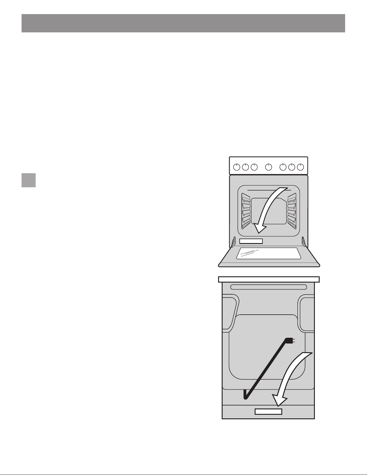
Ubicación del modelo y número de serie
The identication plate is located inside the oven door on
the lower left and the middle-bottom of the back of the
appliance (Fig. 19).
Cuando ordene piezas o pregunte sobre su rango,
siempre asegúrese de incluir los números de modelo y de
serie y un número de lote o letra de la placa de serie de su
rango.
Your identication plate also tells you the rating of the
burners, the type of fuel and the pressure the range was
adjusted for when it left the factory.
Cuidado, limpieza y mantenimiento
Consulte el Manual de uso y cuidado para obtener
instrucciones de limpieza. Si es necesario quitar el rango
para la limpieza o el mantenimiento, apague el suministro
de gas. Desconecte el suministro de gas y electricidad.
Si el suministro de gas o eléctrico es inaccesible, levante
el alcance levemente en la parte delantera y retírelo
de la pared. Tire solo hasta donde sea necesario para
desconectar el suministro de gas y electricidad. Termine
de quitar el rango para dar servicio y limpiarlo. Vuelva a
instalar en orden inverso asegurándose de nivelar el rango
y verique las conexiones de gas para detectar fugas.
Asegúrese de leer y seguir el paso 1 para una instalación
correcta de Anti-tip.
Antes de llamar al servicio
Lea las secciones “Antes de llamar” y la instrucción
de operación en su Manual de uso y cuidado. Puede
ahorrarle tiempo y dinero. La lista incluye las ocurrencias
comunes que no son el resultado de mano de obra o
materiales defectuosos en este electrodoméstico.
Consulte la garantía en su Manual de uso y cuidado para
obtener nuestro número y dirección de servicio gratuito.
Llame o escriba si tiene consultas sobre su producto de
gama y / o necesita pedir piezas.
Fig. 19
10
 Loading...