

Frigidaire FEQBB30DS0 Installation Instructions Manual
Pre-Installation Requirements................................ 2
Frigidaire
Electronic
Installation
Instructions
Gas &
Electric
Electrical Requirements........................................ 2
Ventilation System Requirement s..................................... 3-4
Exhaust System Requirements............................................. 4
Gas Supply Requirements..................................................... 4
Location of Y our Dryer.......................................................... 5
Mobile Home Installation..................................................... 6
Rough-In Dimensions........................................................ 6-7
Unpacking........................................................... 7
Reversing Door Swing........................................... 7
Electrical Installation............................................. 8
Grounding Requirements....................................... 8
Electrical Connections—3-wire.............................. 9
Electrical Connections—4-wire.............................. 9
Gas Connection................................................... 10
Dryer
Before beginning installation, carefully read these instructions. This will simplify the installation and ensure
the dryer is installed correctly and safely . Leave these instructions near the Dryer after inst allation for future
reference.
NOTE: The electrical service to the Dryer must conform with local codes and ordinances and the latest edition of the
National Electrical Code, ANSI/NFPA 70.
NOTE: The gas service to the Dryer must conform with local codes and ordinances and the latest edition of the
National Fuel Gas Code ANSI Z223.1.
NOTE: The Dryer is designed under ANSI Z 21.5.1 or ANSI/UL 2158 - CAN/CSA C22.2 (latest editions) for HOME
USE only. This Dryer is not recommended for commercial applications such as restaurants or beauty salons, etc.
General Installation.............................................. 10
Replacement Parts.............................................. 10
Save These Instructions
www.frigidaire.com
1
P/N 134306200A (0312)
For your safety the information in
this manual must be followed to minimize the
risk of fire or explosion or to prevent property
damage, personal injury or loss of life.
- Do not store or use gasoline or other
flammable vapors and liquid in the vicinity of
this or any other appliance.
- WHA T TO DO IF YOU SMELL GAS
· Do not try to light any appliance.
· Do not touch any electrical switch; do not
use any phone in your building.
· Clear the room, building or area of all
occupants.
· Immediately call your gas supplier from a
neighbor’s phone. Follow the gas supplier's
instructions.
· If you cannot reach your gas supplier, call
the fire department.
POWER SUPPL Y - 3 wire or 4-wire, 240 volt, single phase,
60 Hz, Alternating Current.
POWER SUPPL Y CORD KIT - The dryer MUST employ a
3-conductor power supply cord NEMA 10-30 type SRDT
rated at 240 volt AC minimum, 30 amp., with 3 open end
spade lug connectors with upturned ends or closed loop
connectors OR a 4-conductor power supply cord NEMA
14-30 type SRDT or ST (as required) rated at 240 volt AC
minimum, 30 amp., with 4 open end spade lug connectors
with upturned ends or closed loop connectors and marked
for use with clothes dryers. If being installed in a
manufactured (mobile) home, the dryer MUST employ a
4-conductor power supply cord NEMA 14-30 type SRDT or
ST (as required) rated at 240 volt AC minimum, 30 amp.,
with 4 open end spade lug connectors with upturned ends
or closed loop connectors and marked for use with clothes
dryers. See ELECTRICAL CONNECTIONS for additional
instructions.
OUTLET RECEPT ACLE - NEMA 10-30R (3-wire)
receptacle or NEMA 14-30R (4-wire) receptacle to be
located so the power supply cord is accessible when the
dryer is in the installed position.
Installation and service must be performed by a
qualified installer, service agency or the gas
supplier.
PRE-INSTALLATION REQUIREMENTS
T ools and Materials Required for Installation:
1. Phillip s head screwdriver.
2. Channel-lock adjustable pliers.
3. Carpenter's level.
4. Flat or straight blade screwdriver.
5. Duct tape.
6. Rigid or flexible metal 4 inch (10.2 cm) duct.
7. Vent hood.
8. Pipe thread sealer (Gas).
9. Plastic knife.
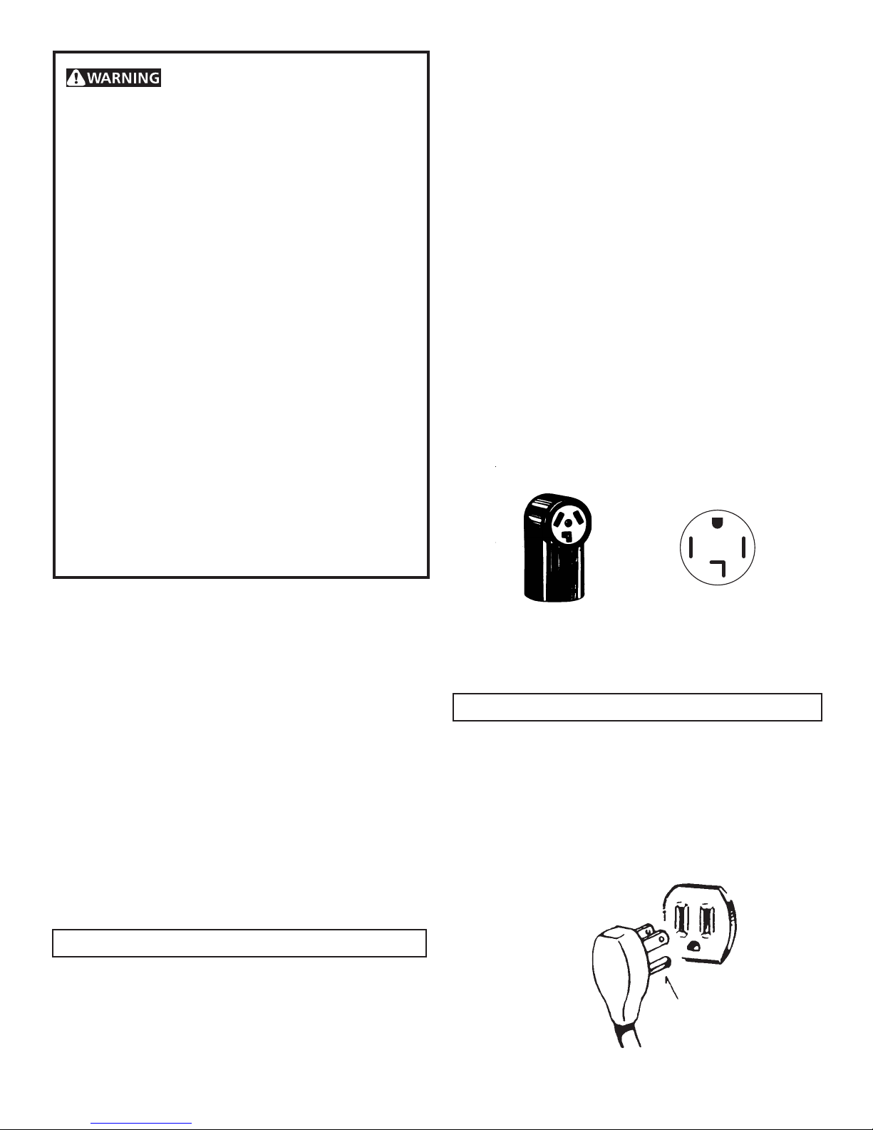
ELECTRICAL REQUIREMENTS
ELECTRIC Dryer
NEMA 10-30R NEMA 14-30R
GAS Dryer
CIRCUIT - Individual 15 amp. branch circuit fused with a 15
amp. maximum time delay fuse or circuit breaker.
POWER SUPPL Y - 3 wire, 120 volt single phase, 60 Hz,
Alternating Current.
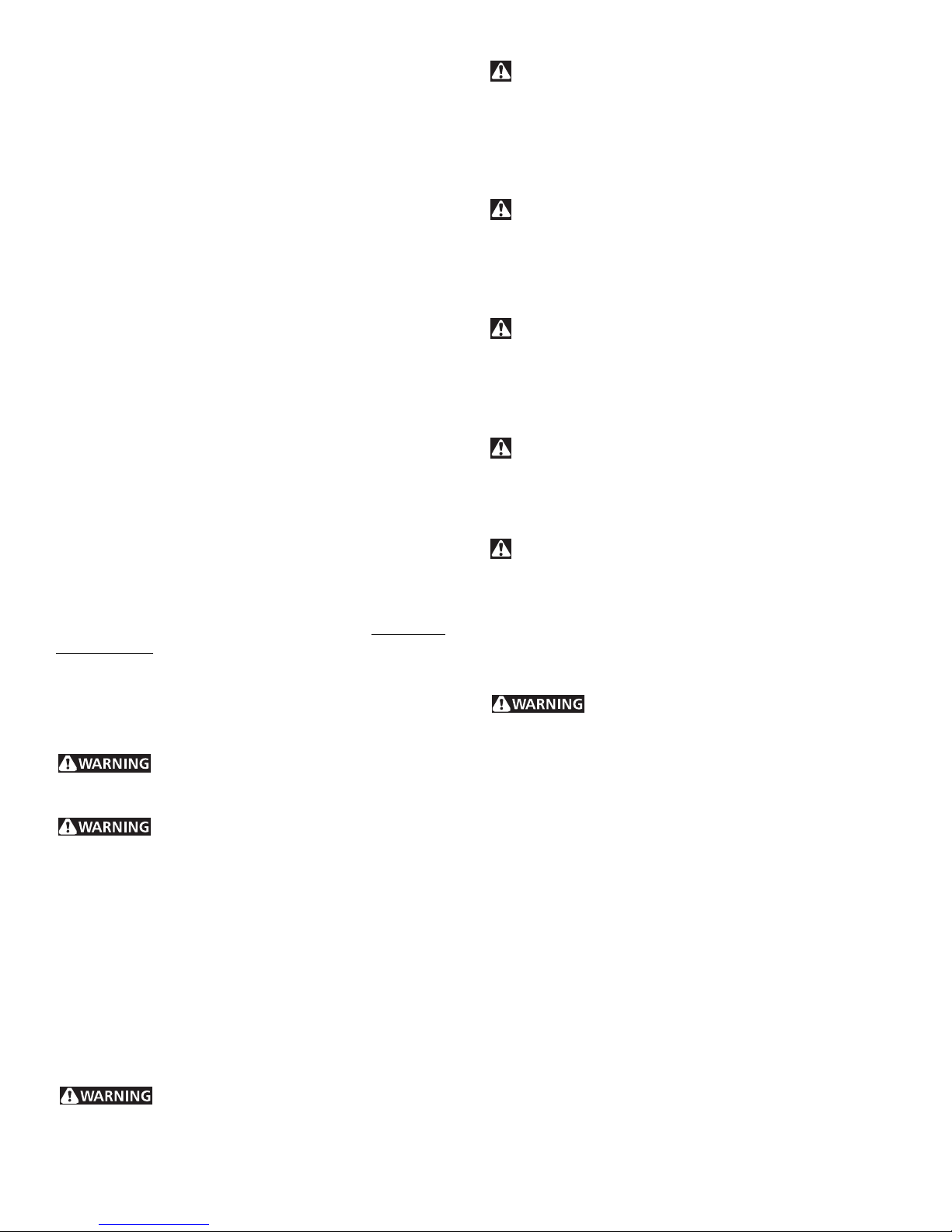
POWER SUPPL Y CORD - The dryer is equipped with a 120
volt 3-wire power cord.
NOTE: Do not under
any circumstances
remove grounding
prong from plug.
CIRCUIT - Individual 30 amp. branch circuit fused with 30
amp. minimum time delay fuses or circuit breakers.
GROUNDING PRONG
2
Printed in U.S.A.
VENTILATION SYSTEM REQUIREMENTS
Air flow (ventilation) through the dryer is critical in the ability of
the dryer to function properly . Heat and air are required to dry
clothes. Heat provides energy to evaporate the moisture in the
clothes. Air is used to carry the heat to the clothes load and
exhaust the evaporated moisture outside. Without adequate air
flow, the heated air can not get to the clothes and they won’t
dry . There are two major components in providing the dryer
with adequate air flow: supply air and an exhaust system. If
either of these are severely restricted, the function of the dryer
will be reduced and in some cases lead to gases building up in
the residence to a dangerous level. Also, the better the air flow ,
the better the drying performance and increased longevity of
the appliance.
SUPPL Y OF MAKEUP AIR
Air that is drawn through the dryer and exhausted outside must
be replaced in the dwelling. The replacement air is known as
make-up air. Make up air is required for all types of household
devices, like furnaces, water heaters, clothes dryers, ranges,
kitchen and bathroom exhaust fans, and fireplaces.
If the dwelling is not properly ventilated, such as in a tightly
constructed house, there may not be enough make up air . If this
condition exists, gases that would normally be vented outside
will be slowed and could build up in the dwelling. Gases will
include carbon monoxide produced during combustion in
appliances such as in furnaces, water heaters, ranges, dryers
and fire places.
T o insure the proper amount of make up air follow: ANZI 223.1
section 8.3.1.5: - “Make up air requirements for the operation of
exhaust fans, kitchen ventilation systems, clothes dryers, and
fireplaces shall be considered in determining the adequacy of a
space to provide air requirements” or Canadian Natural Gas and
Propane Code.
– Improper ventilation could lead to a build up
of gases and a high concentration of carbon monoxide.
Do not use plastic flexible duct to exhaust the dryer.
Excessive lint can build up inside exhaust system and create a fire
hazard and restrict air flow. Restricted air flow will increase dryer
times. If your present system is made up of plastic duct or metal
foil duct, replace it with a rigid or flexible metal duct. Ensure the
present duct is free of any lint prior to installing dryer duct.
If the dryer is not exhausted outdoors, some fine lint will be
expelled into the laundry area. An accumulation of lint in any
area of the home can create a health and fire hazard. The dryer
exhaust system MUST be exhausted to the outside of the
dwelling!
Do not allow combustible materials (for example: clothing,
draperies/curtains, paper) to come in contact with exhaust
system. The dryer MUST NOT be exhausted into a chimney , a
wall, a ceiling, or any concealed space of a building which can
accumulate lint, resulting in a fire hazard.
Exceeding the length of duct pipe or number of elbows
allowed in the "MAXIMUM LENGTH" charts can cause an
accumulation of lint in the exhaust system. Plugging the system
could create a fire hazard, as well as increase drying times.
Do not screen the exhaust ends of the vent system, nor use
any screws or rivets to assemble the exhaust system. Lint can
become caught in the screen, on the screws or rivets, clogging
the duct work and creating a fire hazard as well as increasing
drying times. Use an approved vent hood to terminate the duct
outdoors, and seal all joints with duct tape. All male duct pipe
fittings MUST be installed downstream with the flow of air .
Explosion hazard. Do not install the dryer where
gasoline or other flammables are kept or stored. If the dryer is
installed in a garage, it must be a minimum of 18 inches (45.7 cm)
above the floor. Failure to do so can result in death, explosion,
fire or burns.
– Improper ventilation could starve the dryer of
make up air and could create a fire hazard as well as increase
drying times
EXHAUST SYSTEM REQUIREMENTS
Use only 4 inch (10.2 cm) diameter (minimum) rigid or flexible
metal duct and approved vent hood which has a swing-out
damper(s) that open when the dryer is in operation. When the
dryer stops, the dampers automatically close to prevent drafts
and the entrance of insects and rodents. T o avoid restricting the
outlet, maintain a minimum of 12 inches (30.5 cm) clearance
between the vent hood and the ground or any other obstruction.
The following are specific requirements for
proper and safe operation of your dryer. Failure to follow these
instructions can create excessive drying times and fire
hazards.
In installations where the exhaust system is not described in the
following charts, the following method must be used to determine
if the exhaust system is acceptable:
1 . Connect an inclined or digital manometer between the dryer
and the point the exhaust connects to the dryer .
2 . Set the dryer timer and temperature to air fluff (cool down)
and start the dryer.
3 . Read the measurement on the manometer.
4 . The system back pressure MUST NOT be higher than 0.75
inches of water column. If the system back pressure is less
than 0.75 inches of water column, the system is acceptable. If
the manometer reading is higher than 0.75 inches of water
column, the system is too restrictive and the installation is
unacceptable.
3
 Loading...