

Frigidaire FGB24S5ASE, FGB24L2ECC, FEGB24S5ASE, FGB24S5ABF, FGB24S5DCG Installation Instructions Manual
...
_NSTALLAT_ON AND SERVICE MUST BE PERFORMED BY
A QUAUFIED _NSTALLER.
iMPORTANT: SAVE FOR LOCAL ELECTRICAL iNSPECTOR'S USE.
READ AND SAVE THESE _NSTRUCT_ONS FOR FUTURE REFERENCE.
if the information in this manual is not followed exactly, a fire or explosion may result
causing property damage, personal iniury or death.
FOR YOUR SAFETY:
-- Do not store or use gasoline or other flammable vapors and liquids in the vicinity of this or any other
J WHAT TO DO iF YOU SMELL GAS:
Do not try to light any appliance,
Do not touch any electrical switch; do not use any phone in your building.
immediately call your gas supplier from a neighbor's phone. Follow the gas suppiier's instructions.
if you cannot reach your gas supplier, call the fire department.
-- installation and service must be performed by a qualified installer, service agency or the gas supplier.
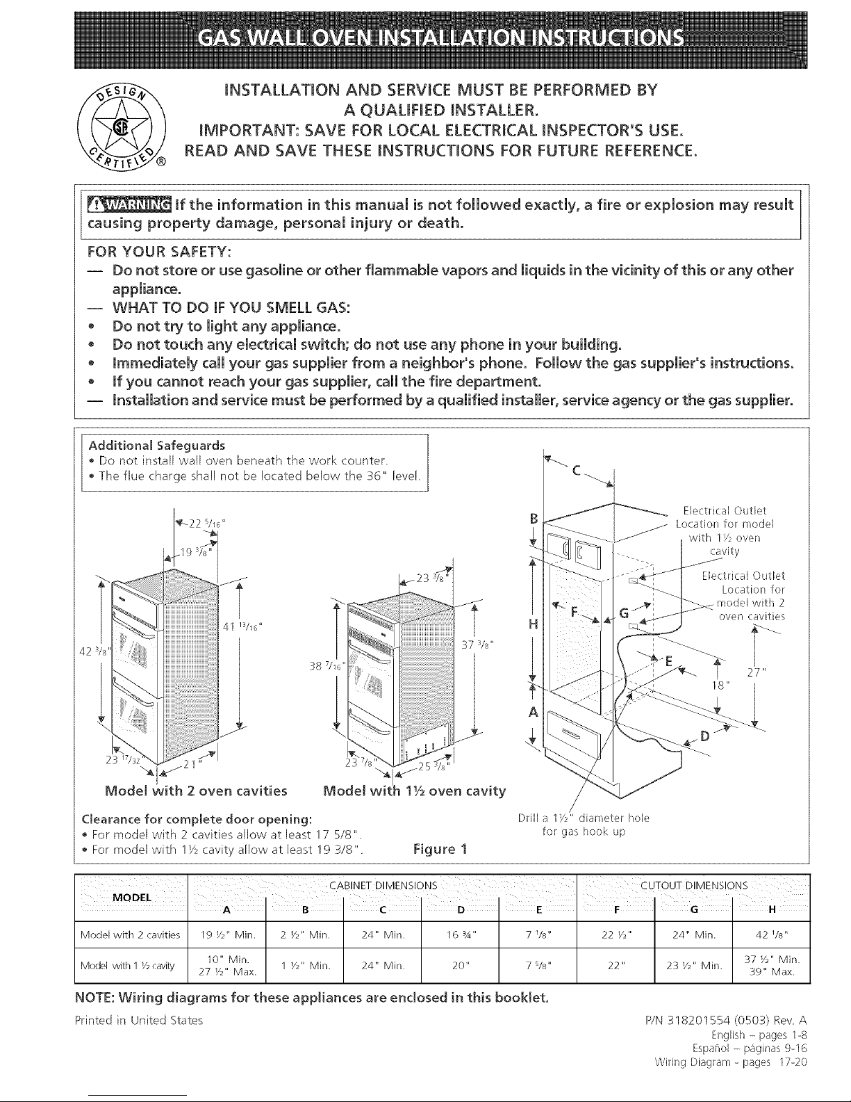
Additional Safeguards
Do not install wall oven beneath the work counter
• The flue charge shall not be located below the 36" level,
42
:_87/16"
23
Model with 2 oven cavities Model
Clearance for complete door opening:
For model with 2 cavities allow at least 17 5/8"
For model with 1Vzcavity allow at least 19 3/8"
11/2oven cavity
Figure 1
Drill a lye" diameter hole
for gas hook up
Electrical Outlet
Location for model
with 1/_ oven
cavity
Electrical Outlet
Location for
model with 2
oven cavities
V
27"
Model with 2 cavities 19 V2" Min. 2 V2" Min. 24" Min. 16 _A" 7 V8" 22 _/2" 24" Min. 42 _/8"
10" Min. 37 Y2" Min.
Model with 1 V2cavity 27 V2" Max. 1 _/_" Min. 24" Min. 20" 7 s/s" 22" 23 _/2" Min. 39" Max.
NOTE: Wiring diagrams for these appliances are enclosed in this booklet.
Printedin United States
P/N 318201554 (0503) Rev A
English - pages 1-8
Espanol - paginas 9-16
Wiring Diagram - pages 17-20
Important Notes to the Installer
1. Read all instructions contained in these installation
instructions before installing the appliance.
2. Remove all packing material and literature from the
oven and broiler compartments before connecting gas
and electric supply.
3. Observe all governing codes and ordinances.
4. Be sure to leave these instructions with the consumer.
Important Note to the Consumer
Keep these instructions with your Use and Care Guide for
future reference.
Savethese instructions for local inspectors.
IMPORTANT SAFETY
INC. NS
POWER FAILURE
Do not attempt to operate the oven in the event
of a power failure, If powwer failure should
occur during operation, turn the oven control to
the OFF position. FaiIure to turn the oven
control off wil! result in oven operation upon
resumption of power to the unit,
Installation of these appliances must conform with local
(.odes or, in the absence of local codes, with the National
Fuel Gas Code ANS! Z223. l--latest edition.
These appliances have been design certified by American
Gas Association (A.G.A.). As with any appliance using
gas and generating heat, there are certain safety
precautions you should follow. You will find them in tile
Use and Care Guide read it carefully.
• Be sure your wall oven is installed and grounded
properly by a qualified installer or service
technician.
• These wall ovens must be electrically grounded in
accordance with local codes or, in their absence,
with the National Electrical Code ANSI/NFPA No.
70--latest edition. See grounding instructions
farther in this manual.
• The installation of appliances designed for
manufactured (mobi[e) home installation must
conform with Manufactured Home Construction
and Safety Standard Title 24CFR, Part 3280
[Formerly the Federal Standard for Mobile Home
Construction and Safety, Title 24, HUD, (Part 280)]
or when such standard is not applicable the
Standard for Manufactured Home installation 1982
(Manufactured Home Sites, Communities and Set-
Ups), ANS! Z225.1/NFPA 501-A- tatest edition, or
with Iota[ codes.
Do not store items or food of interest
to children in the cabinets above the appliance.
Children could be seriously burned or injured if they
(.limb on the appliance to reach these items.
• Do not store or use gasoline or other fJammab[e
vapors and liquids near this or any other
appliance. Explosions or fires could result.
• Be certain all packing materials are removed from the
unit before operating, to prevent fire or smoke damage
should the packing material ignite.
• Do not leave children alone in the kitchen when the
appliance is in use. They should not be allowed to sit
or stand on any part of the appliance, as injury or burns
could result. Keep children from touching the oven
door or glass window when the appliance is operating,
asthe door or window could get hot enough to cause
serious burns.
• Remove broiler tray and other utensils from oven
before using the self-clean cycle (if equipped).
• Do not use the oven asa store space. This createsa
potentially hazardous situation.
Tile appliance requires fresh air for proper burner
combustion. Do not obstruct the flow combustion air at
the oven vent or around the base or beneath the lower
front panel of the appliance. Avoid touching the event
openings or nearby surfaces, as they may become hot.
• Remember, your oven is not designed to heat your
kitchen. Such abuse could result in fire and/or damage
to tile unit and will void your warranty.
1. Carpentry
• Refer to figure I for the dimensions applicable to your
appliance, and the space necessary to receive tile
oven. Corners must be square.
• Floor cabinet must be able to support 150 pounds and
must be flush with bottom of opening.
• Bricked opening (for model with 2 cavities only): If oven
is to be installed in brick or stone, first construct a
rectangular wooden frame with _/2"sides and _/4"top
and bottom. The inside dimensions of this frame must
be the same as the opening dimensions in the figure 1.
Place frame flush in brick opening which shall be snug
fit with the outside of frame. Secure frame to brick.
Overhang of oven trim will cover brick and wood and
will not be exposed. Proceed as in "Cabinet
Installation" section farther.
2. Connect Electricity to Gas WaJJ
Oven
For persona[ safety, these appliances must be
properly grounded°
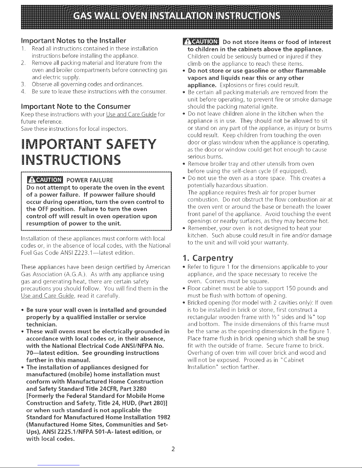
This appliance is equipped with a three-
prong grounding plug for your protection against shock
hazard and must be plugged directly into a properly
grounded receptacle. Do not cut or remove grounding
prong from this plug.
The wall receptacle and circuit should be checked by a
qualified electrician to make sure the receptacle is
properly' grounded.
Grounding -"
type wall
receptacle Power supply cord with
3-prong grounding plug
Figure 2
Where a standard 2-prong wall receptacle is installed, it
is the personal responsibility and obligation of tile
consumer to have it replaced by a properly grounded 3-
prong wall receptacle.
Do not, under any circumstances, cut or remove the
third (ground) prong from the power cord,
If an external electrical source is used, the appliance,
when installed, must be electrically grounded in
accordance with local (:odes or in their absence of local
codes with the National Electric Code ANS!/NFPA No.
70-1987 or latest edition.
Check all code rules and regulations for connecting the
wall oven to be certain the installation conforms with all
local, muni(ipal and state codes as well as local utility
regulations.
Failure to comply with the above could result in a
serious shock hazard.
Note: All hookups and adjustments shall be performed
by qualified technicians.
Disconnect electrical supply cord from
wall receptacle before servicing wall oven.
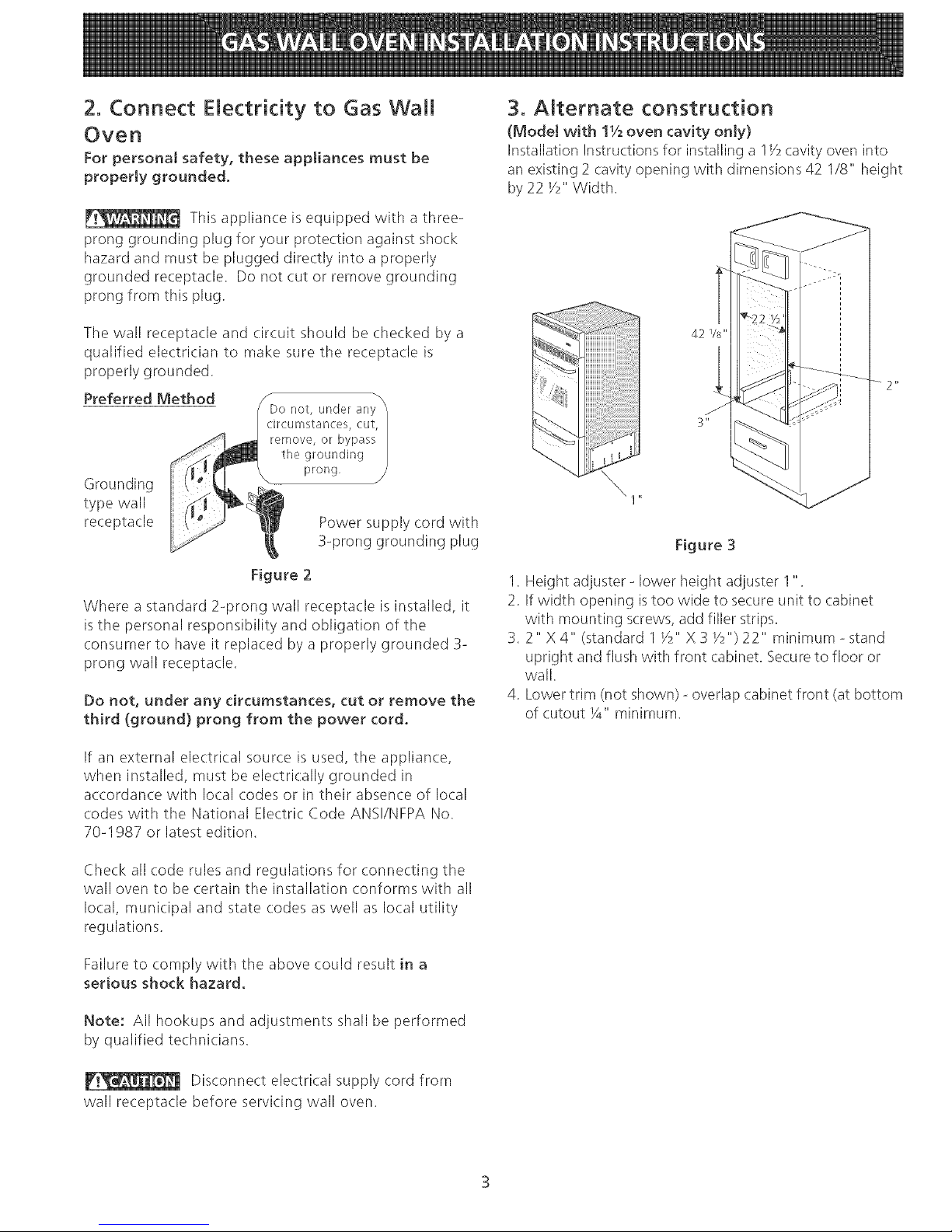
3. Alternate construction
(Mode[ with 11/2oven cavity onJy)
Installation Instructions for installing a 1_/2cavity oven into
an existing 2 cavity opening with dimensions 42 1/8" height
by 22 _/2"Width.
42 Vs"
Figure 3
1. Height adjuster - lower height adjuster 1".
2. If width opening istoo wide to secure unit to cabinet
with mounting screws, add filler strips.
3.2" X 4" (standard 1 Y2" X 3 Y2")22" minimum - stand
upright and flush with front cabinet. Secure to floor or
wail
4. Lower trim (not shown) - overlap cabinet front (at bottom
of cutout 1/4"minimum.
4. Adjusting Oven Height
(Model with 11/2oven cavity only)
Remove and lay aside the lower vent decorative trim
that is taped to the side or to the top of the oven, The
decorative trim will be fastened to the lower front of tile
oven after it has been installed in tile cabinet,
There is a 1 Y2" height adjustment on models with
extension panel (see figure 4). With this adjustment and
a Y2" trim overhang, a unit can be installed in existing
openings 37 Y2" to 39" high.
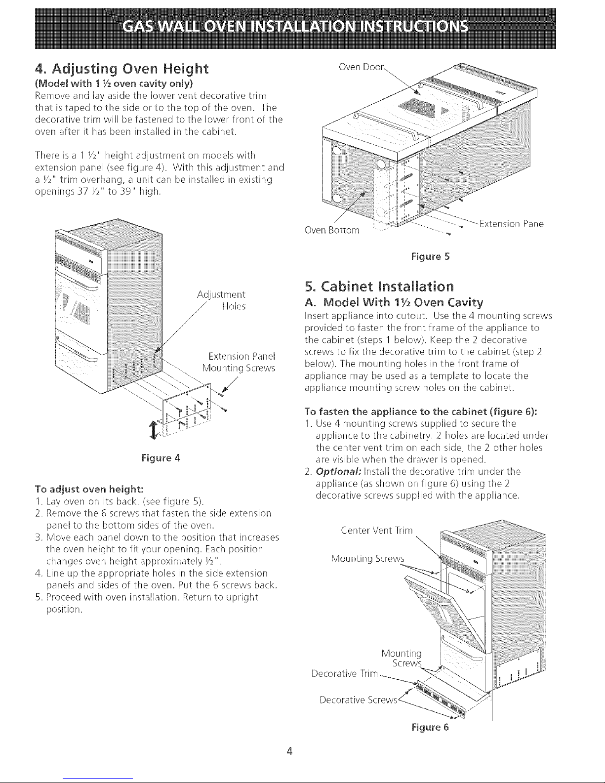
Oven Door.
Adjustment
_ Holes
Y
Extension Panel
Mounting Screws
Figure 4
To adjust oven height:
1. Lay oven on its back. (see figure 5).
2. Remove the 6 screws that fasten the side extension
panel to the bottom sides of the oven.
3. Move each panel down to the position that increases
tile oven height to fit your opening. Each position
changes oven height approximately Y2".
4. Line up tile appropriate holes in tile side extension
panels and sides of the oven. Put the 6 screws back.
5. Proceed with oven installation. Return to upright
position.
Oven Bottom ..... ,,
Panel
Figure 5
5. Cabinet Installation
A. Model With 11/2Oven Cavity
Insert appliance into cutout, Usettle4mountingscrews
provided to fasten tile front frame of the appliance to
the cabinet (steps I below), Keep the 2 decorative
screws to fix the decorative trim to tile cabinet (step 2
below), The mounting holes in the front frame of
appliance may be used as a template to locate tile
appliance mounting screw holes on the cabinet,
To fasten the appliance to the cabinet (figure 6):
1. Use 4 mounting screws supplied to secure the
appliance to the cabinetry. 2 holes are located under
the center vent trim on each side, the 2 other holes
are visible when the drawer is opened.
2. Optional: Install the decorative trim under tile
appliance (as shown on figure 6) using the 2
decorative screws supplied with the appliance.
Center Vent Trim
Mounting Screws
Mounting
Screws
Decorative
Figure 6
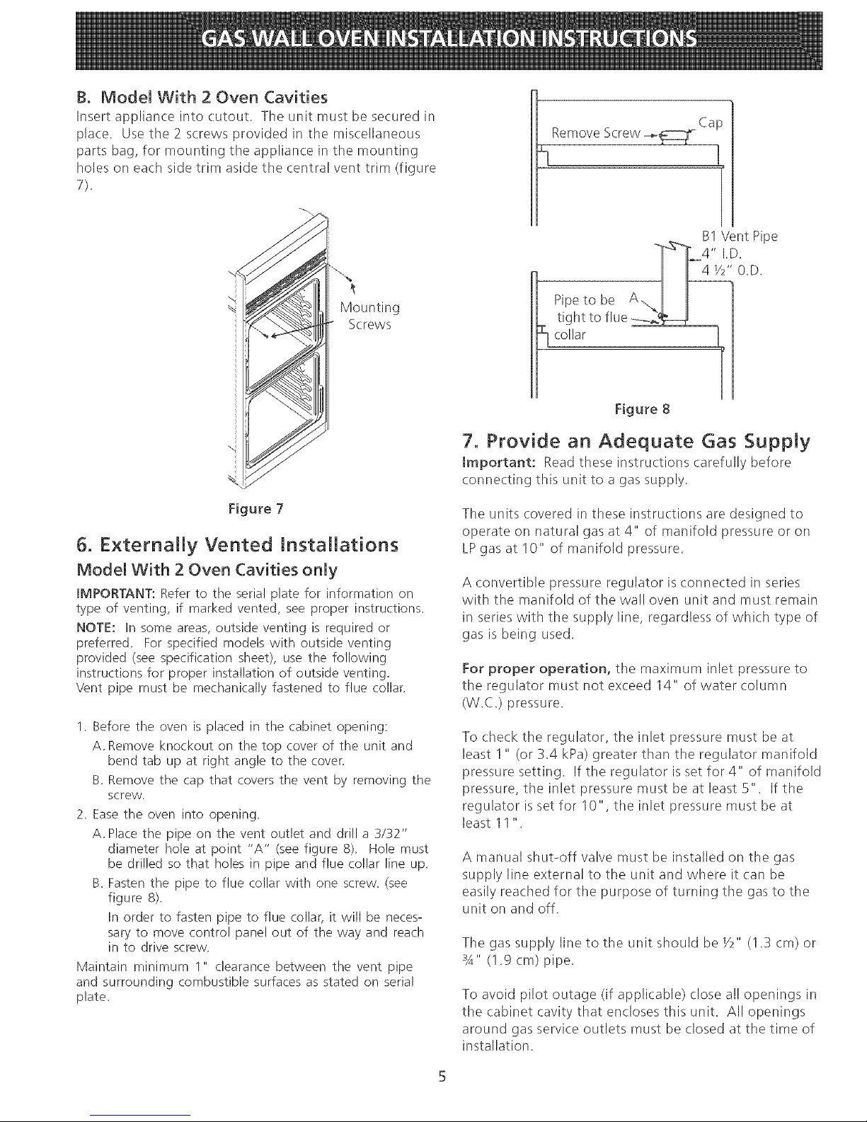
B. Model With 2 Oven Cavities
Insertapplianceintocutout.Tileunitmustbesecuredin
place.Usethe2screwsprovidedinthemiscellaneous
partsbag,formountingtheapplianceinthemounting
holesoneachsidetrimasidetilecentralventtrim(figure
Mounting
Screws
%
Figure7
5. Externally Vented Installations
Model With 2 Oven Cavities only
IMPORTANT: Refer to the serial plate for information on
type of venting, if marked vented, see proper instructions.
NOTE: In some areas, outside venting is required or
preferred. For specified models with outside venting
provided (see specification sheet), use the following
instructions for proper installation of outside venting.
Vent pipe must be mechanically fastened to flue collar.
1. Before the oven is placed in the cabinet opening:
A. Remove knockout on the top cover of the unit and
bend tab up at right angle to the cover.
B. Remove the cap that covers the vent by removing the
screw,
2. Ease the oven into opening,
A. Place the pipe on the vent outlet and drill a 3/32"
diameter hole at point "A" (see figure 8), Hole must
be drilled so that holes in pipe and flue collar line up.
B. Fasten the pipe to flue collar with one screw. (see
figure 8).
In order to fasten pipe to flue collar, it will be neces-
sary to move control panel out of the way and reach
in to drive screw.
Maintain minimum 1" clearance between the vent pipe
and surrounding combustible surfaces as stated on serial
plate.
Ca
Remove Screw -_
B1 Vent Pipe
-i_/24 " I.D.
" 0.D.
tight to flue _.2_11
:_ collar
Figure 8
7. Provide an Adequate Gas Supply
Important: Read these instructions carefully before
connecting this unit to a gas supply.
The units covered in these instructions are designed to
operate on natural gas at 4" of manifold pressure or on
LPgas at 10" of manifold pressure.
A convertible pressure regulator is connected in series
with the manifold of the wall oven unit and must remain
in series with the supply line, regardless of which type of
gas is being used.
For proper operation, the maximum inlet pressure to
the regulator must not exceed 14" of water column
(W.C.) pressure.
To check the regulator, the inlet pressure must be at
least I " (or 3.4 kPa) greater than the regulator manifold
pressure setting. If the regulator is set for 4" of manifold
pressure, the inlet pressure must be at least5". If the
regulator is set for 10", the inlet pressure must be at
least 11".
A manual shut-off valve must be installed on the gas
supply line external to the unit and where it (an be
easily reached for the purpose of turning the gas to the
unit on and off.
The gas supply line to the unit should be Y2" (1.3 cm) or
3A" (1.9 cm) pipe.
To avoid pilot outage (if applicable) close all openings in
the cabinet cavity that encloses this unit. All openings
around gas service outlets must be closed at the time of
installation.
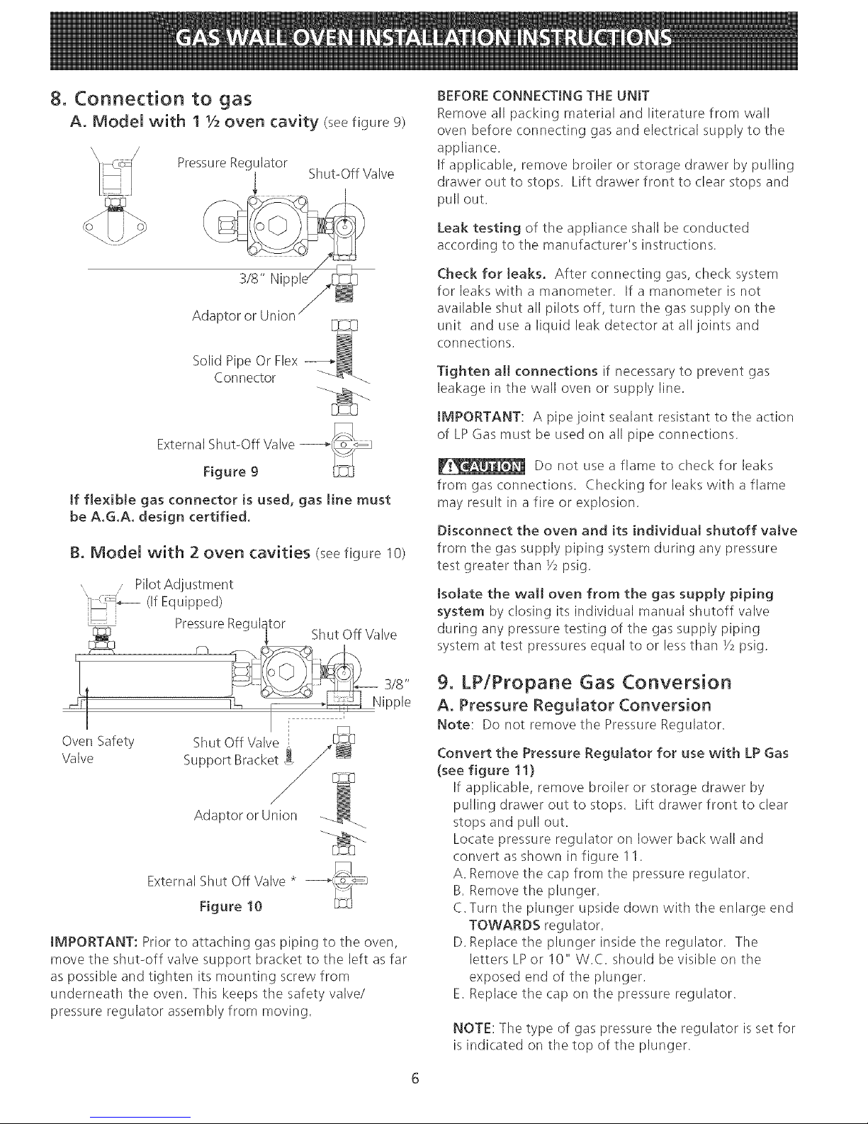
8. Connection to gas
A. Model with 1 1/2oven cavity (seefigure9)
Pressure Regulator
3/8" Nipple//_
Adaptor or Union / _
Solid Pipe Or Flex _--_
Connector _<_
External Shut-Off Valve ---,_L_oo_
Figure 9
[f flexible gas connector is used, gas line must
be A.G.A. design certified.
B. Model with 2 oven cavities (seefigure 10)
Oven Safety
Valve
Pilot Adjustment
(If Equipped)
Pressure Regulator
Shut Off Valve
Support Bracket
Adaptor or Union
Shut Off Valve
External Shut Off Valve *
Figure 10
IMPORTANT: Prior to attaching gas piping to the oven,
move the shut-off valve support bracket to the left as far
as possible and tighten its mounting screw from
underneath the oven. This keeps the safety valve/
pressure regulator assembly from moving.
BEFORE CONNECTING THE UNIT
Remove all packing material and literature from wall
oven before connecting gas and electrical supply to the
appliance.
If applicable, remove broiler or storage drawer by pulling
drawer out to stops. Lift drawer front to clear stops and
pull out.
Leak testing of the appliance shall be conducted
according to the manufacturer's instructions.
Check forteaks. After connecting gas, check system
for leaks with a manometer. If a manometer is not
available shut all pilots off, turn the gas supply on the
unit and use a liquid leak detector at all joints and
connections.
Tighten all connections if necessary to prevent gas
leakage in the wall oven or supply line.
IMPORTANT: A pipe joint sealant resistant to the action
of LP Gas must be used on all pipe connections.
Do not use a flame to check for leaks
from gas connections. Checking for leaks withaflame
may result in a fire or explosion.
Disconnect the oven and its individual shutoff valve
from the gas supply piping system during any pressure
test greater than Y2psig.
Isolate the wail oven from the gas supply piping
system by closing its individual manual shutoff valve
during any pressure testing of the gas supply piping
system at test pressures equal to or lessthan Y2psig.
9. LPiPropane Gas Conversion
A, Pressure Regulator Conversion
Note: Do not remove the Pressure Regulator.
Convert the Pressure Regulator for use with LP Gas
(see figure 11)
If applicable, remove broiler or storage drawer by
pulling drawer out to stops. Lift drawer front to clear
stops and pull out.
Locate pressure regulator on lower back wall and
convert as shown in figure 1I.
A, Remove the cap from tile pressure regulator.
B, Remove the plunger,
C.Turn tile plunger upside down with the enlarge end
TOWARDS regulator,
D. Replace the plunger inside the regulator. The
letters LPor 10" W.C. should be visible on tile
exposed end of the plunger.
E. Replace the cap on the pressure regulator.
NOTE: Tile type of gas pressure the regulator is set for
is indicated on the top of tile plunger.
 Loading...