

Frigidaire FEF356CHSD, FEF356CHTD, FEF387WJCB, FEF388CJSB, FEF389WJCB Installation Guide
...
INSTALLATION AND SERVICE MUST BE PERFORMED BY A QUALIFIED INSTALLER.
IMPORTANT: SAVE FOR LOCAL ELECTRICAL INSPECTOR'S USE.
READ AND SAVE THESE INSTRUCTIONS FOR FUTURE REFERENCE.
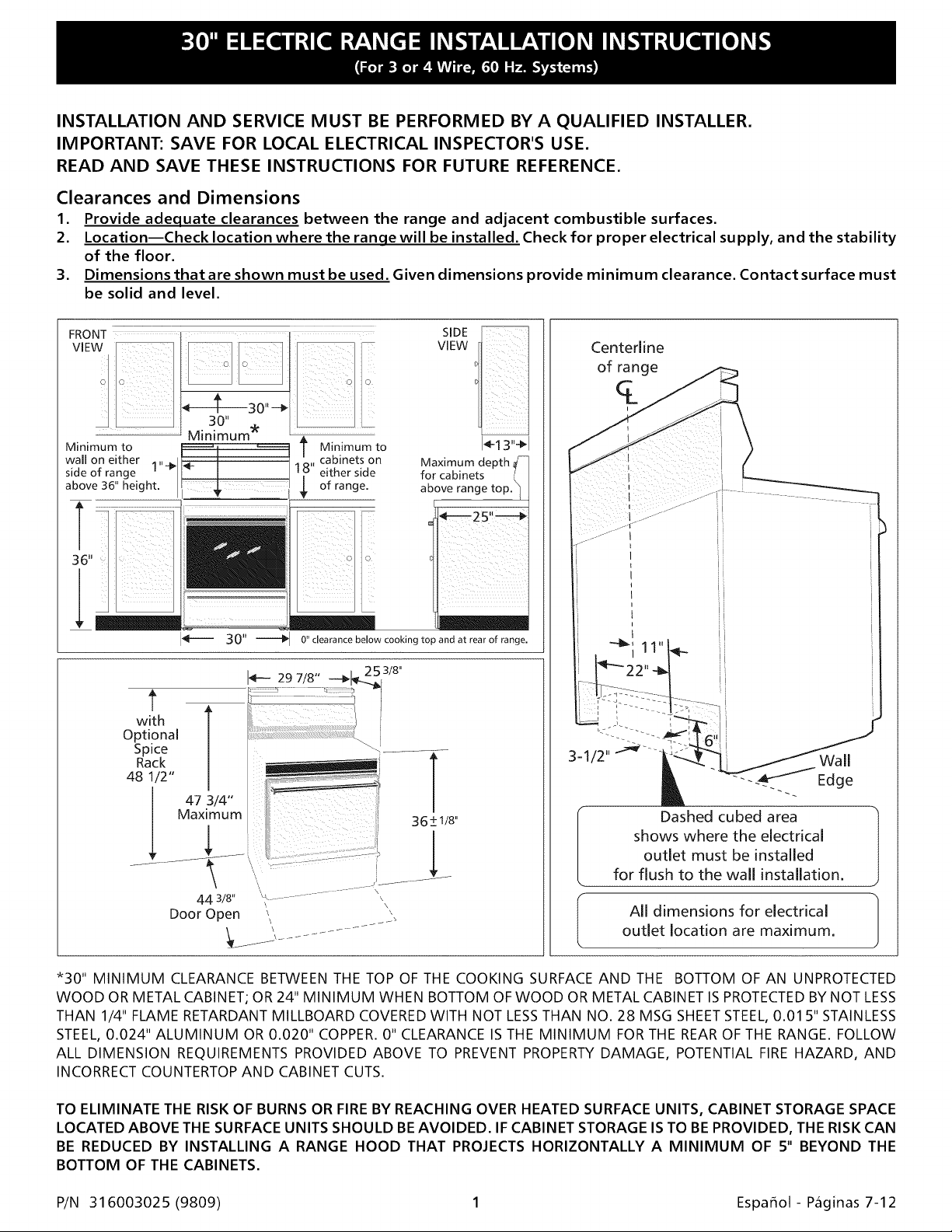
Clearances and Dimensions
1. Provide adequate clearances between the range and adjacent combustible surfaces.
2. Location--Check location where the ranqe will be installed. Check for proper electrical supply, and the stability
of the floor.
3. Dimensions that are shown must be used. Given dimensions provide minimum clearance. Contact surface must
be solid and level.
SIDE
VIEW
..................................
Centerline
of range
q_
i
Minimum to T Minimum to
side of range 1 either side
wall on either i" cabinets on
above 36" height, of range.
r
0" clearance below cooking top and at rear of range.
with
Optional
Spice
Rack
48 1/2"
47 3/4"
Maximum
44 3/8"
Door Open
\
\
\
I_! 3"-_1
Maximum depth,
for cabinets
above range
Dashed cubed area
shows where the electrical
outlet must be installed
for flush to the wall installation.
All dimensions for electrical
outlet location are maximum.
*30" MINIMUM CLEARANCE BETWEEN THE TOP OF THE COOKING SURFACE AND THE BOTTOM OF AN UNPROTECTED
WOOD OR METAL CABINET; OR 24" MINIMUM WHEN BOTTOM OF WOOD OR METAL CABINET IS PROTECTED BY NOT LESS
THAN 1/4" FLAME RETARDANT MILLBOARD COVERED WITH NOT LESS THAN NO. 28 MSG SHEET STEEL, 0.01 5" STAINLESS
STEEL, 0.024" ALUMINUM OR 0.020" COPPER. 0" CLEARANCE IS THE MINIMUM FOR THE REAR OF THE RANGE. FOLLOW
ALL DIMENSION REQUIREMENTS PROVIDED ABOVE TO PREVENT PROPERTY DAMAGE, POTENTIAL FIRE HAZARD, AND
INCORRECT COUNTERTOP AND CABINET CUTS.
TO ELIMINATE THE RISK OF BURNS OR FIRE BY REACHING OVER HEATED SURFACE UNITS, CABINET STORAGE SPACE
LOCATED ABOVE THE SURFACEUNITS SHOULD BEAVOIDED. IF CABINET STORAGE IS TO BE PROVIDED, THE RISKCAN
BE REDUCED BY INSTALLING A RANGE HOOD THAT PROJECTS HORIZONTALLY A MINIMUM OF 5" BEYOND THE
BOTTOM OF THE CABINETS.
P/N 31 6003025 (9809) 1 Espafiol- Paginas 7-12
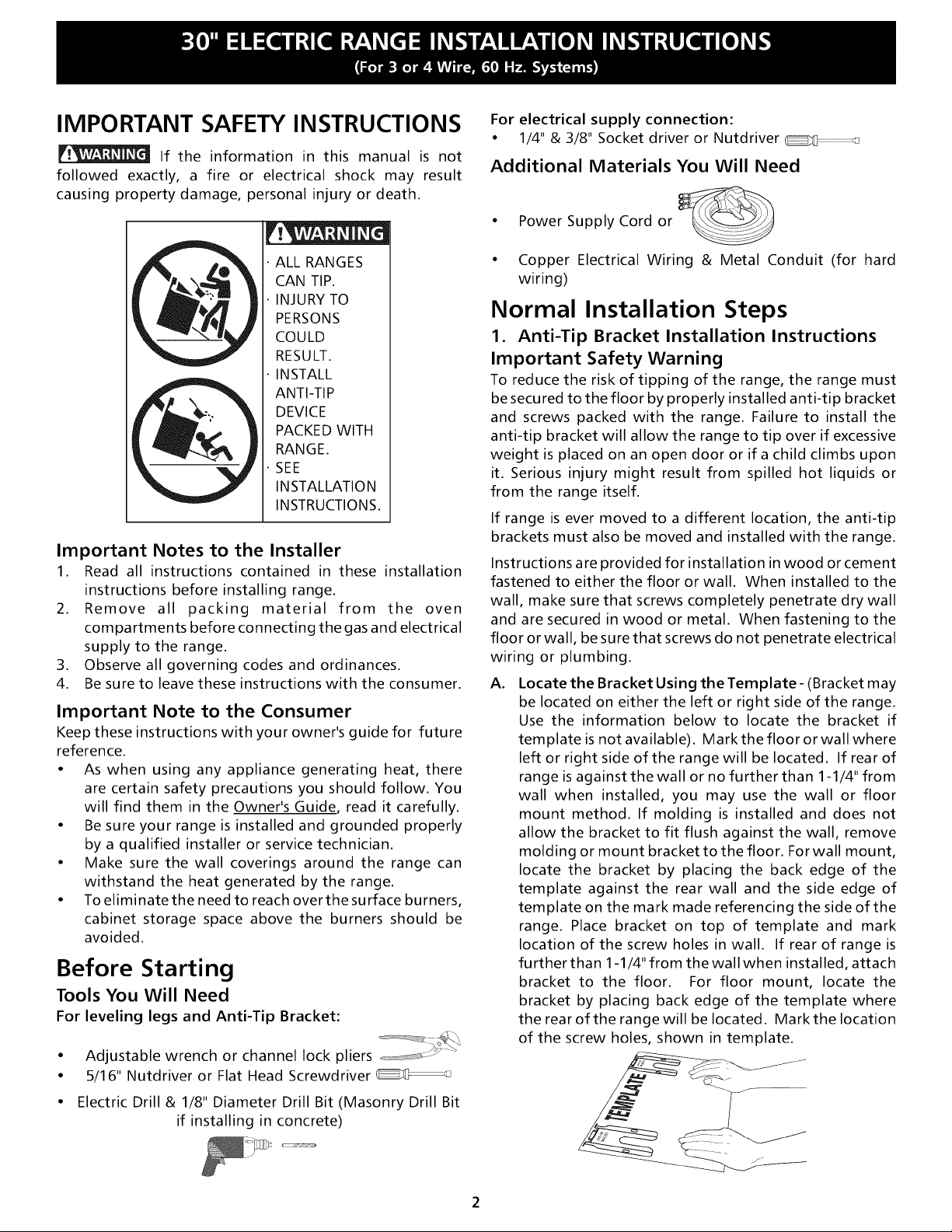
IMPORTANT SAFETY INSTRUCTIONS
If the information in this manual is not
followed exactly, a fire or electrical shock may result
causing property damage, personal injury or death.
For electrical supply connection:
• 1/4" & 3/8" Socket driver or Nutdriver
Additional Materials You Will Need
• Power Supply Cord or
ALL RANGES
CAN TIP.
INJURY TO
PERSONS
COULD
RESULT.
INSTALL
ANTI-TIP
DEVICE
PACKED WITH
RANGE.
SEE
INSTALLATION
INSTRUCTIONS.
Important Notes to the Installer
1. Read all instructions contained in these installation
instructions before installing range.
2. Remove all packing material from the oven
compartments before connecting the gas and electrical
supply to the range.
3. Observe all governing codes and ordinances.
4. Be sure to leave these instructions with the consumer.
Important Note to the Consumer
Keep these instructions with your owner's guide for future
reference.
• As when using any appliance generating heat, there
are certain safety precautions you should follow. You
will find them in the Owner's Guide, read it carefully.
• Be sure your range is installed and grounded properly
by a qualified installer or service technician.
• Make sure the wall coverings around the range can
withstand the heat generated by the range.
• To eliminate the need to reach over the surface burners,
cabinet storage space above the burners should be
avoided.
Before Starting
Tools You Will Need
For leveling legs and Anti-Tip Bracket:
• Adjustable wrench or channel lock pliers ==_ :J _"
• 5/16" Nutdriver or Flat Head Screwdriver
• Copper Electrical Wiring & Metal Conduit (for hard
wiring)
Normal Installation Steps
1. Anti-Tip Bracket Installation Instructions
Important Safety Warning
To reduce the risk of tipping of the range, the range must
be secured to the floor by properly installed anti-tip bracket
and screws packed with the range. Failure to install the
anti-tip bracket will allow the range to tip over if excessive
weight is placed on an open door or if a child climbs upon
it. Serious injury might result from spilled hot liquids or
from the range itself.
If range is ever moved to a different location, the anti-tip
brackets must also be moved and installed with the range.
Instructions are provided for installation in wood or cement
fastened to either the floor or wall. When installed to the
wall, make sure that screws completely penetrate dry wall
and are secured in wood or metal. When fastening to the
floor or wall, be sure that screws do not penetrate electrical
wiring or plumbing.
A,
Locate the Bracket Using the Template- (Bracket may
be located on either the left or right side of the range.
Use the information below to locate the bracket if
template is not available). Mark the floor or wall where
left or right side of the range will be located. If rear of
range is against the wall or no further than 1-1/4" from
wall when installed, you may use the wall or floor
mount method. If molding is installed and does not
allow the bracket to fit flush against the wall, remove
molding or mount bracket to the floor. For wall mount,
locate the bracket by placing the back edge of the
template against the rear wall and the side edge of
template on the mark made referencing the side of the
range. Place bracket on top of template and mark
location of the screw holes in wall. If rear of range is
further than 1-1/4" from the wall when installed, attach
bracket to the floor. For floor mount, locate the
bracket by placing back edge of the template where
the rear of the range will be located. Markthe location
of the screw holes, shown in template.
• Electric Drill & 1/8" Diameter Drill Bit (Masonry Drill Bit
if installing in concrete)
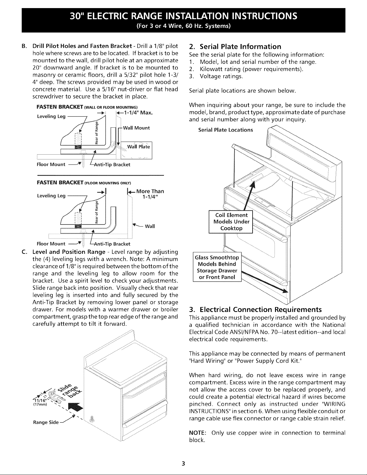
B.
Drill Pilot Holes and Fasten Bracket - Drill a 1/8" pilot
hole where screws are to be located. If bracket is to be
mounted to the wall, drill pilot hole at an approximate
20 ° downward angle. If bracket is to be mounted to
masonry or ceramic floors, drill a 5/32" pilot hole 1-3/
4" deep. The screws provided may be used in wood or
concrete material. Use a 5/16" nut-driver or flat head
screwdriver to secure the bracket in place.
FASTEN BRACKET (WALL OR FLOOR MOUNTING)
Leveling Leg -- b\
----_i 14--1=1/4" Max.
Floor Mount
i iiii:i
Floor Mount
C.
Level and Position Range - Level range by adjusting
'ily
ip Bracket
the (4) leveling legs with a wrench. Note: A minimum
clearance of 1/8" is required between the bottom of the
range and the leveling leg to allow room for the
bracket. Use a spirit level to check your adjustments.
Slide range back into position. Visually checkthat rear
leveling leg is inserted into and fully secured by the
Anti-Tip Bracket by removing lower panel or storage
drawer. For models with a warmer drawer or broiler
compartment, grasp the top rear edge of the range and
carefully attempt to tilt it forward.
2. Serial Plate Information
See the serial plate for the following information:
1. Model, lot and serial number of the range.
2. Kilowatt rating (power requirements).
3. Voltage ratings.
Serial plate locations are shown below.
When inquiring about your range, be sure to include the
model, brand, product type, approximate date of purchase
and serial number along with your inquiry.
Serial Plate Locations
Coil Element
Models Under
Cooktop
Glass Smoothtop _ "_
Models Behind
or Front Panel
Storage Drawer __
3. Electrical Connection Requirements
This appliance must be properly installed and grounded by
a qualified technician in accordance with the National
Electrical Code ANSI/NFPA No. 70--latest edition--and local
electrical code requirements.
This appliance may be connected by means of permanent
"Hard Wiring" or "Power Supply Cord Kit."
When hard wiring, do not leave excess wire in range
compartment. Excess wire in the range compartment may
not allow the access cover to be replaced properly, and
could create a potential electrical hazard if wires become
pinched. Connect only as instructed under "WIRING
INSTRUCTIONS" in section 6. When using flexible conduit or
range cable use flex connector or range cable strain relief.
NOTE: Only use copper wire in connection to terminal
block.
3A. Models with Factory Connected Power
Supply Cord
NOTE: Some models may be equipped with a factory
connected three (3) conductor power supply cord.
Mobile home installation or areas where local codes do not
permit grounding through neutral, a four (4) conductor
power supplycord kit rated at 125/250 volts minimum, and
marked for use with ranges shall be used. See Range
Connection Opening Size Chart for cord kit ampere rating
information. Terminals on end of wires must be either
closed loop or open-end spade lugs with upturned ends.
3B. Models Requiring Power Supply Cord Kit
RISK OF FIRE OR ELECTRICAL SHOCK MAY OCCUR IF AN
INCORRECT SIZE RANGE CORD KIT IS USED, THE
INSTALLATION INSTRUCTIONS ARE NOT FOLLOWED OR
STRAIN RELIEF BRACKET IS DISCARDED.
This appliance may be connected by means of a power
supply cord. Only a power supply cord kit rated at 125/250
volts minimum, and marked for use with ranges shall be
used. See chart on page 3 for cord kit ampere rating
information. Cord must have either three (3) or four (4)
conductors. Terminals on end of wires must be either
closed loop or open-end spade lugs with upturned ends.
Cord must have strain relief clamp.
See section 5Afor 3-wire or section 5B for 4-wire connection.
4. Electrical Connection to Range
The rear access cover must be removed. To remove, loosen
center screw (one screw) and remove access cover. The
terminal block will then be accessible.
/
Access I"-""
Cover /
of Range
/
Rear
Range Connection Opening Size Chart
Refer to chart below for proper range connection opening size and power
supply cord kit ampere rating information. See serial plate on range for
kilowatt rating data.
See Serial Plate on Range for
KW Rating
120/240 Volts 120/208 Volts
0-8.7 KW 0-7.8 KW 30 Amp 1-1/8 in. 7/8 in.
8.8-16.5 KW 7.9-12.5 KW 40 Amp 1-3/8 in. 1-1/8 in.
16.6-22.5 KW 12.6-18.5 KW 50 Amp 1-3/8 in. 1-3/8 in.
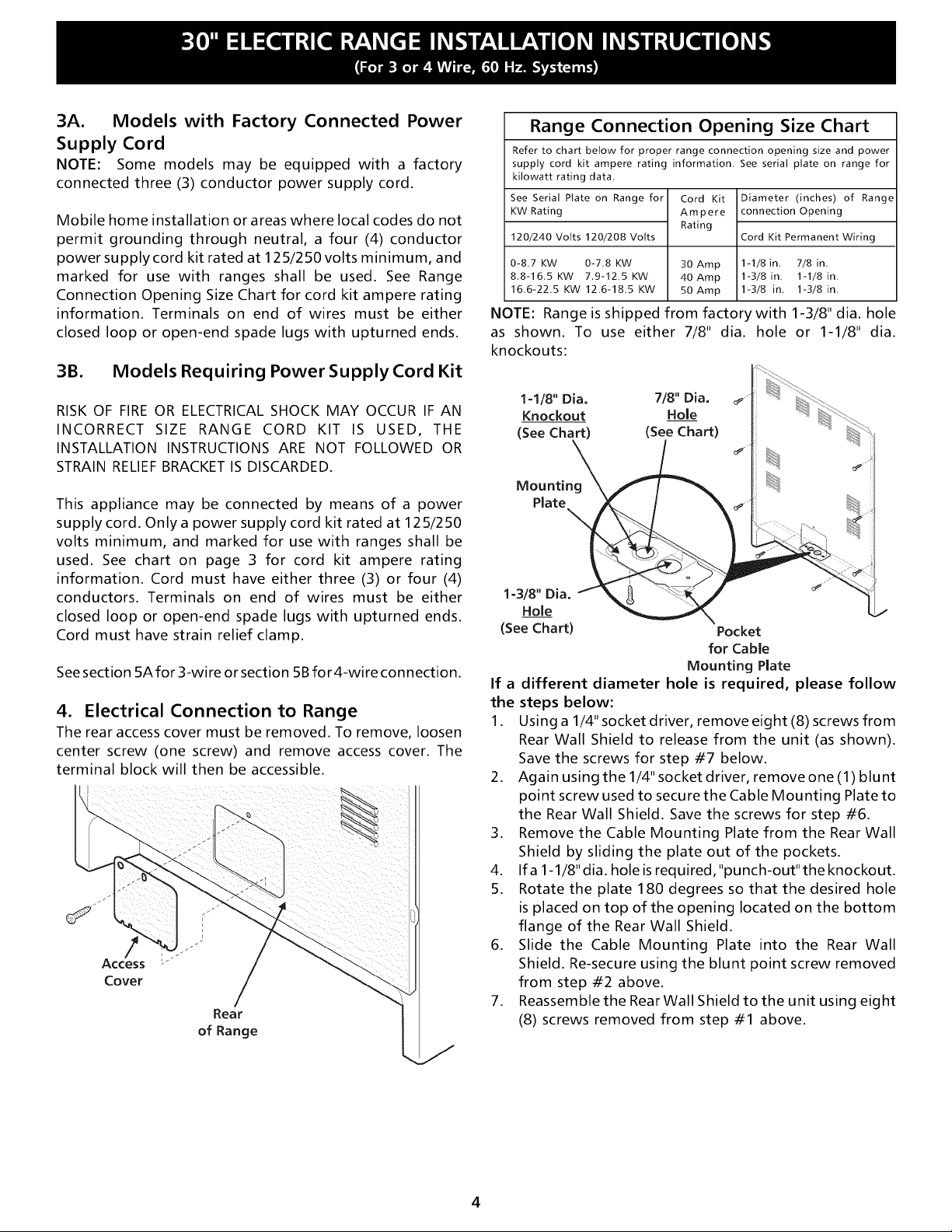
NOTE: Range is shipped from factory with 1-3/8" dia. hole
as shown. To use either 7/8" dia. hole or 1-1/8" dia.
knockouts:
1-1/8" Dia. 7/8" Dia.
Knockout Hole
(See Chart) (See Chart)
Mounting
Plate
1=3/8" Dia.
Hole
(See Chart)
If a different diameter hole is required, please follow
the steps below:
1. Using a 1/4" socket driver, remove eight (8) screws from
Rear Wall Shield to release from the unit (as shown).
Save the screws for step #7 below.
2. Again using the 1/4" socket driver, remove one (1) blunt
point screw used to secure the Cable Mounting Plate to
the Rear Wall Shield. Save the screws for step #6.
3. Remove the Cable Mounting Plate from the Rear Wall
Shield by sliding the plate out of the pockets.
4. Ifa 1-1/8"dia. holeisrequired,"punch-out"theknockout.
5. Rotate the plate 180 degrees so that the desired hole
is placed on top of the opening located on the bottom
flange of the Rear Wall Shield.
6. Slide the Cable Mounting Plate into the Rear Wall
Shield. Re-secure using the blunt point screw removed
from step #2 above.
7. Reassemble the Rear Wall Shield to the unit using eight
(8) screws removed from step #1 above.
Cord Kit
Ampere
Rating
Diameter (inches) of Range
connection Opening
Cord Kit Permanent Wiring
Pocket
for Cable
Mounting Plate
4
 Loading...