

Page 1
INSTALLATION INSTRUCTIONS
ELECTRIC BUILT-IN
INSTALLATION AND SERVICE MUST BE PERFORMED BY A QUALIFIED INSTALLER
SINGLE AND DOUBLE OVEN MODELS
IMPORTANT NOTE TO INSTALLER: Before you begin – read these
instructions completely and carefully. Be sure to leave these instructions with the consumer.
IMPORTANT NOTE TO CONSUMER: Keep these instructions with your
use and care book for future reference. Observe all gover ning codes
and ordinances. Save these instructions for local inspectors.
Your new wall oven has been designed to fit a wide variety of cutout
sizes to make the job of installing easier. The first step of your
installation should be to measure your current cutout dimensions and
compare them to the cutout dimension chart for your model shown on
page 2. You may find that little or no cabinet work will be necessary.
1. CARPENTRY
Refer to Figures 1 or 2 for the dimensions applicable to
your model oven, and the space necessary to receive the
oven. The oven support surface may be solid plywood or
similar material, however the surface must be level from
side to side and from front to rear.
2. ELECTRICAL REQUIREMENTS
OBSERVE ALL GOVERNING CODES
AND LOCAL ORDINANCES
IMPORTANT: SAVE THESE INSTRUCTIONS FOR
THE LOCAL ELECTRICAL INSPECTOR’S USE.
A. A three-wire or four-wire single phase 120/240 Volt,
60 Hz AC only electrical supply (or three-wire or fourwire 120/280 Volt if specified on nameplate) is required
on a separate circuit fused on both sides of the line
(time-delay fuse or circuit breaker is recommended). DO
NOT fuse neutral. The fuse size must not exceed the
circuit rating of the appliance specified on the
nameplate.
NOTE: Wire sizes and connections must conform with
the fuse size and rating of the appliance in accordance
with the National Electrical Code and local codes and
ordinances.
WARNING: AN EXTENSION CORD SHOULD NOT BE
USED WITH THIS APPLIANCE. SUCH USE MAY RESULT IN
A FIRE, ELECTRICAL SHOCK, OR OTHER PERSONAL
INJURY.
B. The appliance should be connected to the fused
disconnect (or circuit breaker) box through flexible
armored or non-metallic sheathed cable. The flexible
armored cable extending from the appliance should be
connected directly to the junction box. The junction box
should be located as shown in Figure 1 with as much
slack as possible remaining in the cable between the box
and the appliance, so it can be moved, if servicing is ever
necessary.
C. A suitable strain relief must be provided to attach
the flexible armored cable to the junction box.
- 1 -
318064300 (9806) Rev. B
Printed in Canada
Page 2
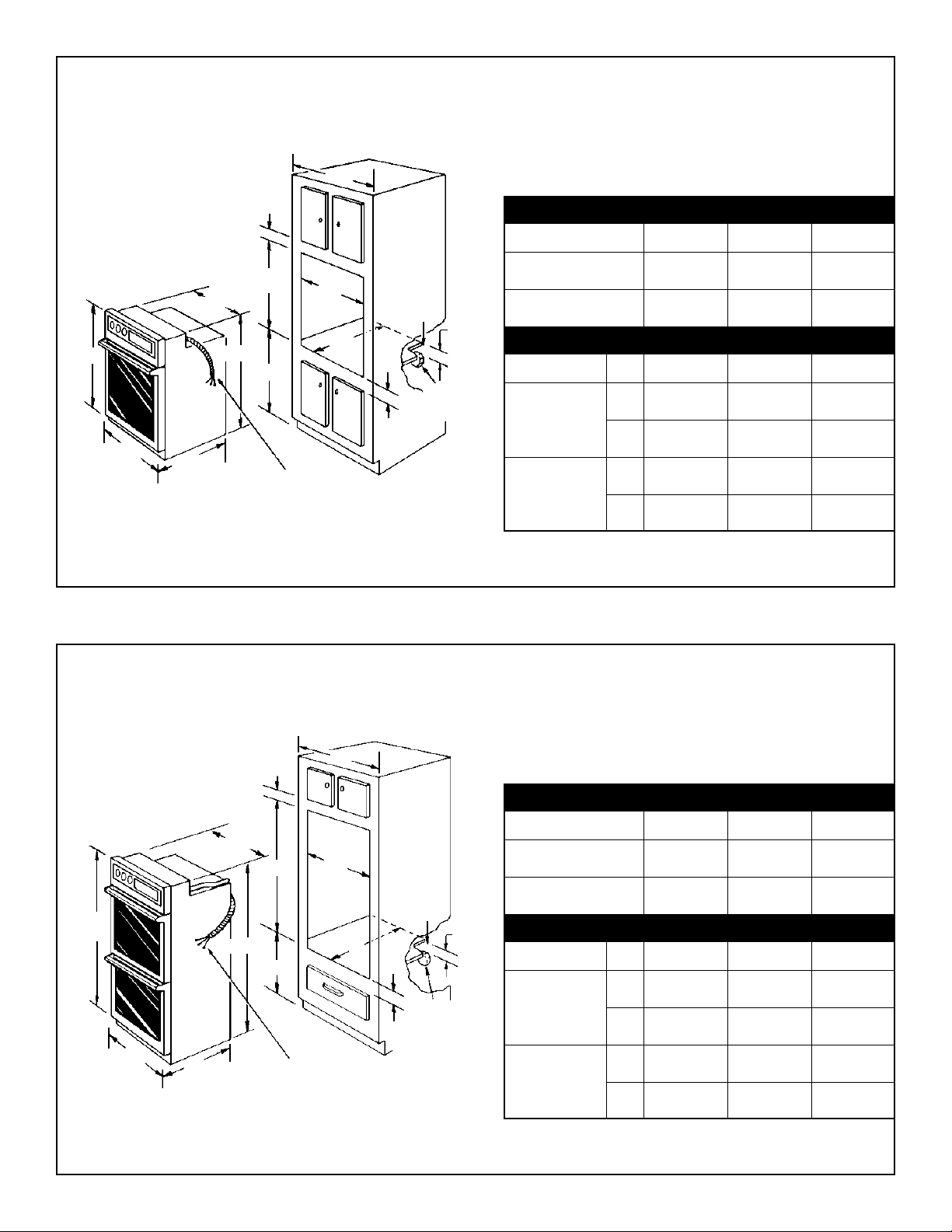
24” AND 27” SINGLE OVENS
C
1-1/2”
MIN.
Allow at least 19-3/8” clearance for complete oven door
opening as show in FIGURE 8.
DO NOT INSTALL THIS OVEN IN A BASE CABINET
WITH A COUNTERTOP ABOVE IT.
PRODUCT DIMENSIONS AND CABINET WIDTH
30-3/4”
D
B
28-1/32”
31”
*
A
25-3/8”
6’ CABLE
*
E
F
18” MINIMUM
24” AND 27” DOUBLE OVENS
CABLE
1-7/8”
MIN.
HOLE
FOR
3”
MAX.
ELECTRICAL
JUNCTION
BOX
FIGURE 1
MODEL
24” SINGLE OVEN
27” SINGLE OVEN
ABC
23-7/8” 21-11/16” 24” MIN.
26-7/8” 24-11/16” 27” MIN.
CUTOUT DIMENSIONS
MODEL D E F
24”
Min.
28-1/8” 22” 23-1/2”
SINGLE
OVEN
27”
Max.
30-1/8” 22-1/4” –
Min.
28-1/8” 24-7/8” 23-1/2”
SINGLE
OVEN
Max.
30-1/8” 25-1/4” –
Allow at least 19-3/8” clearance for complete oven door
opening as show in FIGURE 8.
49-1/4”
1-1/2”
MIN.
C
PRODUCT DIMENSIONS AND CABINET WIDTH
B
MODEL
D
47-3/4”
11-1/2”
A
25-3/8”
6’ CABLE
E
HOLE
FOR
CABLE
3”
F
1-7/8”
MIN.
MAX.
ELECTRICAL
JUNCTION
BOX
24” DOUBLE OVEN
27” DOUBLE OVEN
CUTOUT DIMENSIONS
MODEL D E F
24”
Min.
DOUBLE
OVEN
27”
Max.
Min.
ABC
23-7/8” 21-11/16” 24” MIN.
26-7/8”
27-1/8” **
24-11/16” 27” MIN.
48” 22” 23-1/2”
50” 22-1/4” –
48” 24-7/8” 23-1/2”
DOUBLE
OVEN
Max.
49-7/8” 25-1/4” –
** 27-1/8” on stainless steel models.
FIGURE 2
- 2 -
Page 3
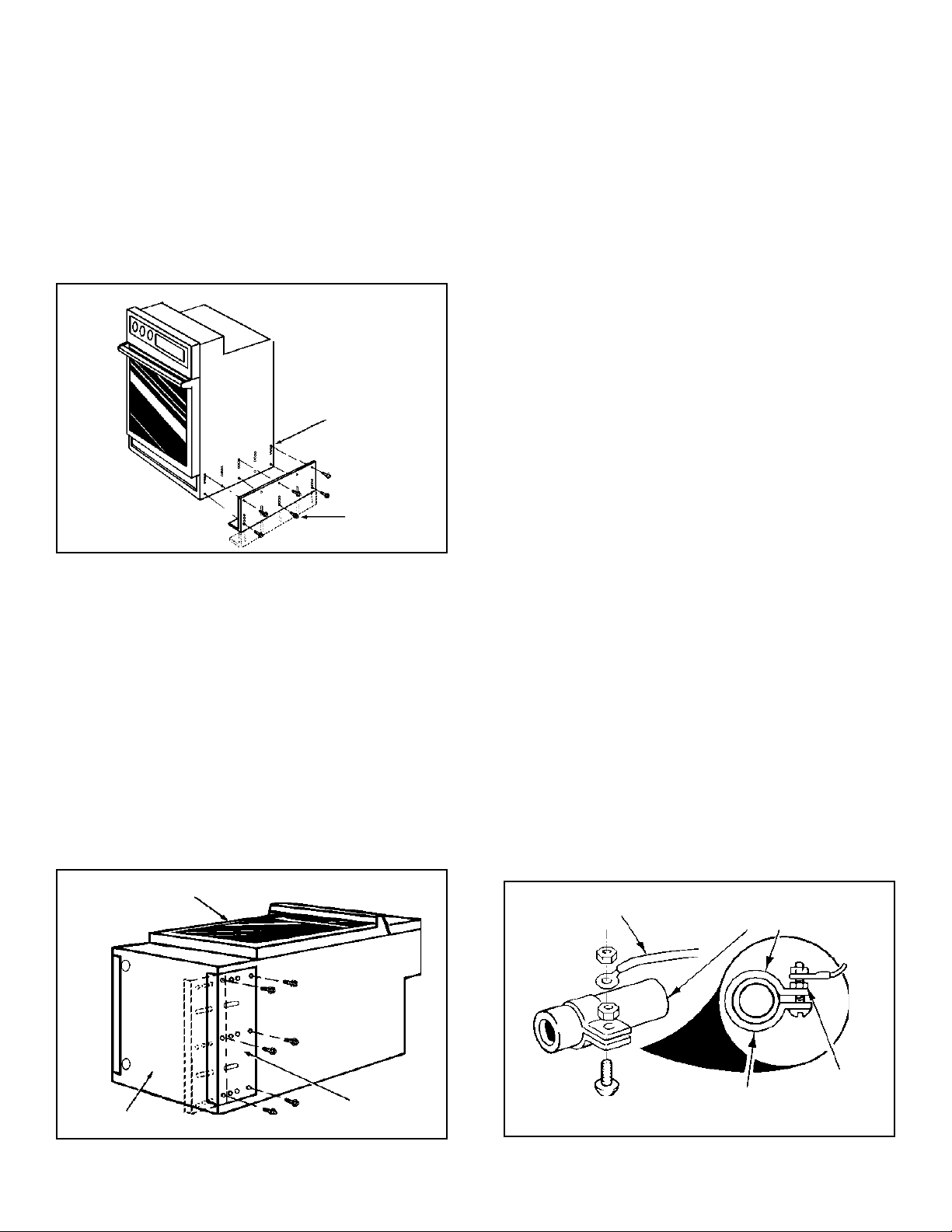
3. HEIGHT ADJUSTMENT ON OVEN
4. ELECTRICAL CONNECTION
Remove and lay aside the lower vent grille that is taped to
the outer side panel of the oven. The grille will be fastened
to the lower front of the oven after it has been installed in
the cabinet.
There is a 1-1/2” height adjustment on these models. (see
figure 4) With this adjustment and a 1/2” trim overhang, a
unit can be installed in existing openings 48” to 50” high
(double oven) or 28-1/8” to 30-1/8” (single oven).
ADJUSTMENT
HOLES
EXTENSION
PANEL
MOUNTING
SCREWS
It is the personal responsibility and obligation of the
customer to contact a qualified installer to assure that the
electrical installation is adequate and is in conformance
with the National Electrical Code and local code
ordinances.
ELECTRICAL GROUND IS REQUIRED
ON THIS APPLIANCE.
This appliance is equipped with copper lead wires. If
connection is made to aluminum house wiring, use only
special connectors which are approved for joining copper
and aluminum wires in accordance with the National
Electrical Code and local codes and ordinances.
This appliance is manufactured with a white neutral power
supply wire and a frame connected bare ground wire.
A. If local codes permit connection of the frame
grounding conductor to the neutral (white wire),
connect the bare wire and white wire from the supply
cable of the appliance together and to the neutral (white)
wire in the junction box. Connect the remaining wires
from the supply cable, matching colors to the wires in the
junction box.
Figure 4
To adjust oven height:
A. Lay oven on its back. (see figure 5)
B. Remove the 6 screws that fasten the side extension
panel to the bottom sides of the oven.
C. Move each panel down to the position that increases
the oven height to fit your opening. Each position changes
oven height approximately 1/2”.
D. Line up the appropriate holes in the side extension
panels and sides of the oven. Replace the 6 screws.
E. Proceed with oven installation. Return oven to upright
position.
OVEN DOOR
B. If used in mobile home or if local codes DO NOT
permit frame grounding to the neutral, separate the
white and bare ground wires that extend out of the end of
the supply cable of the appliance. Connect the white wire
from the supply cable to the neutral white wire in the
junction box. Connect the black wire from the supply
cable to the black wire in the junction box. Connect the
red wire from the supply cable to the red wire in the
junction box. The bare wire must now be used to ground
the appliance in accordance with local electrical codes.
Connect the bare copper ground wire to a grounded cold
water pipe* or to the grounded lead in the service panel.
Do not ground to a gas supply pipe. Do not connect to
electrical power supply until appliance is permanently
grounded. Connect the ground wire befor e turning on the
power. (see figure 6)
COPPER
GROUND WIRE
GROUNDED COLD
WATER PIPE
(REMOVE PAINT, ETC.)
OVEN
BOTTOM
Figure 5
EXTENSION
PANEL
- 3 -
GROUND CLAMP
(MUST BE TIGHT
ON PIPE)
Figure 6
TIGHTEN
NUTS FIRMLY
Page 4

CAUTION: If connecting to a four-wire electrical system
(mobile home) the appliance frame MUST NOT be
connected to the neutral wire of the four-wire electrical
system. Separate the white and bare wires that extend out
of the end of the supply cable of the appliance. Connect
the white, red and black wires from the supply cable,
matching the colors to the corresponding wires in the
junction box. Connect the bare ground wire from the
supply cable to the ground wire in the junction box.
6. CHECKING OPERATION
SINGLE AND DOUBLE OVEN MODELS
Some wall ovens have manually operated control knobs
to set the Clock and the oven Bake, Broil or Clean
functions. Refer to the Owner’s Guide supplied in the
literature package and check all controls for correct
operation.
* Cold water pipe must have metal continuity to electrical
ground and not be interrupted by plastic, rubber or other
electrically insulating connectors (including water meter or
pump) without adding a jumper wire at these connections.
5. INSTALLATION
Insert appliance into cut-out. Screws are provided for
fastening the front frame on the appliance to the cabinet.
The mounting holes in the front frame of appliance may be
used as a template to locate the appliance mounting screw
holes.
To fasten the appliance to the cabinetry:
1. Line up the 2 mounting holes on the grill with the
lower mounting holes on each side of the oven frame,
below the oven door. (see figure 7)
2. Use 2 screws from the miscellaneous parts bag to
secure the grill and appliance to the cabinetry.
3. Use the remaining 2 screws for mounting the appliance in the upper two mounting holes on each side of the
oven frame, above the door.
This wall oven may be equipped with an electronic oven
control. Each one of the electronic control functions have
been factory checked before shipping this appliance.
However, it is suggested that you verify the operation of
the electronic oven controls once more. For using the
electronic control refer to the Owner’s Guide. Follow the
setting instructions for the Clock, Timer, Bake, Broil,
Convection (some models) and Clean functions.
Bake – After setting the oven to 350°F for baking, the
lower oven element should become red.
Broil – When the oven is set to broil the upper oven
element should become red.
Clean – When the oven is set for a self-cleaning cycle, the
upper element should become red during the preheat
portion of the clean cycle. After reaching the self-cleaning
temperature, the lower heating element will be on and
should become red.
Convection (some models) – When the oven is set for
convection baking or roasting both the upper and the
lower oven heating elements will be on and the convection
fan will turn. The convection fan will stop turning when
the oven door is opened during convection baking or
roasting.
Figure 7
Figure 8
MTG. SCREW
LOWER
VENT GRILL
MINIMUM
REQUIREMENT
FOR
COMPLETE
OVEN DOOR
OPENING.
MTG.
SCREW
19-3/8”
SIDE
VIEW
IMPORTANT NOTE:
Some models have a small fan located inside the control
panel for additional cooling of the electrical and electronic
components. The fan will continue to turn after the oven
has been operating at high temperatures as is obtained
during oven self-cleaning.
SERIAL PLATE LOCATION
The Serial Plate is located along the side of the oven door in
the open position.
BEFORE YOU CALL FOR SERVICE
Check to make sure the house fuses or circuit breaker for
your oven are not blown or open.
- 4 -
Page 5

INSTRUCCIONES PARA LA INSTALACIÓN
HORNO ELÉCTRICO EMPOTRADO
LA INSTALACIÓN Y EL SERVICIO DEBE DE HACERLOS UN INSTALADOR CALIFICADO
DOBLE Y SENCILLO MODELOS DE HORNO
AVISO IMPORTANTE PARA EL INSTALADOR: Antes de empezar, lea con
atención todas estas instrucciones. No se olvide de dejar estas instrucciones
con el usuario.
AVISO IMPORTANTE PARA EL USUARIO: Guarde estas instrucciones con el
libro de mantenimiento y utilización para futuras referencias. Siga todos las
indicaciones y los códigos vigentes. Guarde estas instrucciones para los
inspectores locales.
Su horno de pared ha sido diseñado para adaptarse a un número diverso de
huecos con distintas medidas, y hacer el trabajo de instalación mas fácil. El
primer paso para su instalación debe de ser el de medir las dimensiones de la
apertura y compararlas con las que se indican en el cuadro de dimensiones del
hueco de la página número 2, para su modelo. Puede ocurrir que no sea casi
necesario hacer trabajo de carpintería.
1. CARPINTERÍA
Consulte las figuras 1 o 2 para conocer las dimensiones
pertinentes al modelo de su horno y al espacio necesario
en el que poner el horno. La superficie donde se va a
apoyar el horno debe de ser de madera contrachapada
solida o otro material similar y, sobre todo, la superficie
tiene que estar a nivel, de lado a lado, y de atrás hacia
adelante.
2. REQUISITOS ELÉCTRICOS
CUMPLA CON TODOS LOS CÓDIGOS EN VIGOR Y
TODOS LOS REGLAMENTOS LOCALES.
IMPORTANTE: GUARDE ESTAS INSTRUCCIONES
PARA USO DEL INSPECTOR ELÉCTRICO LOCAL.
A. Para el suministro eléctrico solamente se necesita
corriente alterna con frecuencia de 60 Hz y fase única de
120/240 voltios suministrada por cable de tres o de
cuatro alambres (o si se especifica así en la placa,
corriente de 120/208 voltios suministrada con un cable
de tres o de cuatro alambres) en un circuito separado
con fusibles en ambos lados de la línea (se recomienda
un fusible de tiempo retardado o un cortacircuitos). NO
ponga un fusible en el hilo neutro. El tamaño del fusible
no tiene que exceder la capacidad del circuito necesario
para el electrodomestico y la cual se especifica en la
placa.
NOTA: El tamaño de los cables y de las conexiones debe
de estar en conformidad con el tamaño del fusible y con
la capacidad del electrodomestico y de acuerdo con el
Código Eléctrico Nacional y los códigos y reglamentos
locales.
AVISO: NO SE DEBE DE USAR UNA ALARGADORA PARA
ENCHUFAR ESTE ELECTRODOMESTICO. ESTO PODRÍA
RESULTAR EN UN FUEGO, UN CHOQUE ELECTRICO U
OTRO TIPO DE DAÑO PERSONAL.
B. Este electrodomestico debe conectarse a la caja de
fusibles (o de cortacircuitos), por medio de un cable
blindado flexible o un cable con forro no metálico. El
cable blindado flexible que va desde el electrodomestico
debe de estar conectado directamente a la caja de
empalme. La caja de empalme debe de estar localizada
en el lugar que se indica en la figura 1, dejando tanto
exceso de cable como sea posible entre la caja y el
electrodomestico, de forma que así el electrodomestico
se pueda mover fácilmente, si fuera necesario para hacer
una reparación.
C. Se debe de usar un conectador que reduzca la
tirantez de una forma adecuada para unir el cable
blindado flexible a la caja de empalme.
- 1 -
318064300 (9806) Rev. B
Impreso en Canadá
Page 6

HORNOS SENCILLOS
DE 24 Y 27 PULGADAS
MÍNIMO 1-1/2
PULGADAS
Deje por lo menos 19-3/8 pulgadas de espacio para
que la puerta se pueda abrir completamente, como se
indica en la figura 8.
NO INSTALE ESTE HORNO EN LA PARTE DE ABAJO
C
DE UN ARMARIO DE COCINA QUE TIENE UN
MOSTRADOR ENCIMA.
DIMENSIONES DEL APARATO Y ANCHURA DEL ARMARIO
D
B
25-3/8”
28-1/32”
31”
*
6 PIES DE CABLE
MÍNIMO 18 PULGADAS
*
30-3/4”
A
FIGURA 1
HORNOS DOBLOS
DE 24 Y 27 PULGADAS
MODELO
E
F
AGUJERO
PARA EL
CABLE
MÁXIMO
3
PULGADAS
HORNO SENCILLO
DE 24 PULGADAS
HORNO SENCILLO
DE 27 PULGADAS
MÍNIMO 17/8
PULGADAS
CAJA
ELÉCTRICA DE
EMPALME
MODELO D E F
HORNO
DIMENSIONES DEL HUECO
Mín.
ABC
23-7/8” 21-11/16” 24” MÍN.
26-7/8” 24-11/16” 27” MÍN.
28-1/8” 22” 23-1/2”
SENCILLO
DE 24”
HORNO
Máx.
30-1/8” 22-1/4” –
Mín.
28-1/8” 24-7/8” 23-1/2”
SENCILLO
DE 27”
Máx.
30-1/8” 25-1/4” –
Deje por lo menos 19-3/8 pulgadas de espacio para
que la puerta del horno se pueda abrir
completamente, como se indica en la figura 9.
49 1/4”
MÍNIMO 1-1/2
PULGADAS
B
D
47-3/4”
11-1/2”
A
25-3/8”
6 PIES DE CABLE
C
DIMENSIONES DEL APARATO Y ANCHURA DEL ARMARIO
MODELO
HORNO DOBLE
E
AGUJERO
PARA EL
CABLE
F
MÁXIMO
PULGADAS
DE 24 PULGADAS
HORNO DOBLE
DE 27 PULGADAS
3
DIMENSIONES DEL HUECO
ABC
23-7/8” 21-11/16” 24” MÍN.
26-7/8”
24-11/16” 27” MÍN.
27-1/8” **
MODELO D E F
CAJA
MÍNIMO
1-7/8
PULGADAS
ELÉCTRICA DE
EMPALME
HORNO
DOBLE
DE 24”
HORNO
Mín.
Máx.
Mín.
48” 22” 23-1/2”
50” 22-1/4” –
48” 24-7/8” 23-1/2”
DOBLE
FIGURA 2
DE 27”
** 27-1/8” para el modelo de acero inoxidable
- 2 -
Máx.
49-7/8” 25-1/4” –
Page 7

3. AJUSTE DE LA ALTURA DEL HORNO
Retire y deje a un lado la rejilla que está sujeta con cinta
adhesiva al panel exterior del horno. Esta rejilla se
sujetará a la parte baja frontal del horno, después de que
este se haya instalado en el armario.
En estos modelos hay 1 1/2 pulgadas de ajuste en la
altura (vea la figura 4). Con este ajuste y 1/2 pulgada del
borde que sobresale, el electrodomestico puede
instalarse en huecos de 48 a 50 pulgadas de alto (para
horno doble) o de 28 1/8 a 30 1/8 pulgadas (para horno
sencillo).
AGUJEROS
DE AJUSTE
TORNILLOS
DE MONTAJE
PARA AL
DE EXTENSIÓN
Figura 4
Para ajustar la altura del horno:
A. Ponga el horno apoyado en la parte trasera. (vea la
figura 5)
B. Quite los 6 tornillos que sujetan el panel de
extensión lateral a la parte inferior de los lados del
horno.
C. Mueva cada panel hacia abajo, hasta la posición que
aumenta la altura del horno para que se adapte a la
apertura que usted tiene. Cada posición cambia la altura
del horno 1/2 pulgada aproximadamente.
D. Alinee los agujeros apropiados en los paneles de
extensión y en los lados del horno. Vuelva a poner los 6
tornillos.
E. Proceda con la instalación del horno. Vuelva a poner
el horno en posición vertical.
PUERTA DEL HORNO
4. CONEXIÓN ELÉCTRICA
El usuario tiene la responsabilidad personal y la obligación
de utilizar un instalador calificado, para asegurar que la
instalación eléctrica está hecha de forma adecuada y está
conforme con el Código Eléctrico Nacional y con los
reglamentos locales.
EN ESTE ELECTRODOMESTICO SE NECESITA UN
CABLE DE TOMA A TIERRA.
Este electrodomestico viene equipado con cables de
conexión de cobre. Si estos tuvieran que conectarse a los
cables de aluminio de una casa, use solamente los conectores especiales aprobados para empalmes de cobre y
aluminio, de acuerdo con el Código Eléctrico Nacional y los
reglamentos y códigos locales.
Este electrodomestico se ha fabricado con un cable para el
suministro de energía que tiene un alambre neutro de color
blanco y un alambre pelado de toma a tierra conectado al
armazón exterior.
A. Si los códigos locales permiten la conexión del
conductor de toma a tierra del armazón al neutro
(alambre blanco), una el alambre pelado y el alambre
blanco del cable de suministro de energía del
electrodomestico juntos al cable neutro (blanco) en la caja
de empalme. Conecte los alambres restantes desde el cable
de suministro de energía, emparejando los colores con los
de los cables en la caja de empalme.
B.
Si este horno se va a usar en una casa sobre
ruedas o si los códigos locales no permiten que el
armazón este conectado al neutro de la toma a tierra,
separe el alambre blanco y el de toma a tierra pelado que
salen del final del cable de suministro de energía al
electrodomestico. Conecte el alambre blanco del cable de
suministro de energía al alambre blanco neutro en la caja de
empalme. Conecte el alambre negro del cable de suministro
de energía al alambre negro en la caja de empalme.
Conecte el alambre rojo del cable de suministro de energía
al alambre rojo de la caja de empalme. El alambre pelado
debe de usarse ahora para la toma a tierra del
electrodomestico de acuerdo con los códigos eléctricos
locales. Conecte el alambre de cobre pelado de toma a
tierra a una tubería de toma a tierra de agua fría* o al
alambre de toma a tierra en el panel de servicio. No conecte
la toma a tierra a una tubería de suministro de gas. No
conecte el suministro de energía eléctrica hasta que el
electrodomestico tenga su toma a tierra instalada
permanentemente. Conecte el alambre de toma a tierra
antes de enchufar por primera vez el electrodomestico. (vea
la figura 6)
CABLE DE TOMA A
TIERRA DE COBRE
CABLE DE TOMA A TIERRA A
LA TUBERÍA DE AGUA FRÍA
(QUITE LA PINTURA, ETC.)
PARTE DE ABAJO
DEL HORNO
Figura 5
PANEL DE
EXTENSIÓN
- 3 -
ARGOLLA PARA SUJETAR EL
CABLE DE TOMA A TIERRA
(DEBE DE ESTAR BIEN SUJETA A
LA TUBERÍA)
Figura 6
AJUSTE LAS
TUERCAS
FIRMEMENTE
Page 8

ADVERTENCIA: Si está conectado a un sistema eléctrico
de cuatro alambres (casa movible), el armazón del
eletrodomestico NO TIENE QUE estar conectado al alambre
neutro del sistema eléctrico de cuatro alambres. Separe el
alambre blanco y el alambre pelado que salen del extremo
final del cable de suministro de energía del
electrodomestico. Conecte el alambre blanco, el rojo y el
negro del cable de suministro de energía, emparejando los
colores con los alambres correspondientes en la caja de
empalme. Conecte el alambre pelado de toma a tierra
desde el cable de suministro de energía al alambre de toma
a tierra en la caja de empalme.
* La tubería de agua fría debe de tener una continuidad de
metal hasta la toma a tierra eléctrica y no puede estar
interrumpida por plástico, goma u otros conectores de
aislamiento eléctrico (incluyendo un manómetro o bomba
de agua) al menos que se instale un cable de conexión
alrededor de cada uno de estos puntos.
5. INSTALACIÓN
Coloque el electrodomestico en el hueco. Se proveen los
tornillos para sujetar el frente del armazón del
electrodomestico al armario. Los agujeros de montaje en la
parte frontal del armazón del electrodomestico pueden
usarse como una plantilla para situar los agujeros para los
tornillos de montaje del electrodomestico.
Para sujetar el electrodomestico al armario:
1. Alinee los dos agujeros de montaje en la rejilla con los
agujeros de montaje a cada lado de la parte inferior del
armazón del horno, debajo de la puerta del horno. (vea la
figura 7)
2. Use dos tornillos de la bolsa de piezas variadas para
asegurar la rejilla y el electrodomestico a los armarios.
3. Utilice los dos tornillos que quedan para montar el
electrodomestico en los dos agujeros de montaje a cada
lado de la parte superior del armazón del horno, encima de
la puerta.
6. VERIFICACIÓN DEL FUNCIONAMIENTO
MODELOS DE HORNO SENCILLO Y DOBLE
Algunos hornos de pared tienen botones para control
manual del reloj y de las funciones de Hornear, Asar o
Limpiezar. Mire la Guía del Usuario suministrada en el
paquete de información y verifique que todos los
controles funcionan correctamente.
Este horno de pared puede estar equipado con un
control electrónico para el horno. Cada una de las
funciones electrónicas ha sido verificada en la fabrica
antes de que el electrodomestico haya sido enviado. Sin
embargo, se sugiere que verifique el funcionamiento de
los controles electrónicos del horno una vez más. Para
saber como utilizar el control electrónico del horno mire
la Guía del Usuario y siga las instrucciones para poner en
funcionamiento el reloj, el minutero, el horno, el asador,
el horno de convección (solo en algunos modelos) y el
sistema de limpieza.
Hornear – Después de poner el horno a 350 F para
hornear, el elemento de la parte de abajo del hor no se
debe de ponerse rojo.
Asar – Cuando se pone el horno para asar, el elemento
de arriba del horno debe de ponerse rojo.
Limpiezar – Cuando el horno se pone en el ciclo para
que se limpie a si mismo, el elemento de arriba debe de
ponerse rojo durante la parte de pre-calentamiento del
ciclo de limpieza. Después de que llegue a la
temperatura adecuada de limpieza, el elemento de
calentamiento inferior se encenderá y debe de ponerse
rojo.
Horno de convección (solamente en algunos
modelos) – Cuando el horno se pone para hornear o
asar con convección, ambos elementos de
calentamiento, el superior y el inferior, se encenderán y
el ventilador de convección empezará a funcionar. El
ventilador de convección se parará cuando se abre la
puerta del horno cuando se está horneando o asando
con convección.
Figura 7
Figura 8
TORNILLO DE
MONTAJE
REJILLA PARA LA
VENTILACIÓN POR
DEL HORNO
COMPLETAMENTE.
MEDIDAS
MÍNIMAS
QUE SE
REQUIEREN
PARA QUE
LA PUERTA
SE PUEDA
ABRIR
ABAJO
TORNILLO
DE
MONTAJE
19-3/8”
VISTA
LATERAL
NOTA IMPORTANTE:
Algunos modelos tienen un ventilador pequeño situado
dentro del panel de control para enfriamiento adicional
de los componentes eléctricos y electrónicos. El
ventilador continuará funcionando después de que el
horno haya estado operando a una temperatura alta,
como a la que se llega cuando el horno se está
limpiando.
LOCALIZACIÓN DE LA PLACA
CON EL NÚMERO DE SERIE
La placa con el número de serie se puede encontrar en el
lado de la puerta del horno, cuando está abierta.
ANTES DE LLAMAR AL SERVICIO DE
REPARACIONES
Verifique que los fusibles de la casa no se hayan fundido
o el cortacircuitos del horno no haya saltado.
- 4 -
 Loading...