

Frigidaire FEB30T7DCB Data Sheet

SERVICE DATA SHEET 318047305 (0406) Rev. B
Electric Double Wall Ovens with Electronic Oven Control
NOTICE
This service data sheet is intended for use by persons having electrical and mechanical training and a level of
knowledge of these subjects generally considered acceptable in the appliance repair trade. The manufacturer
cannot be responsible, nor assume any liability, for injury or damage of any kind arising from the use of
this data sheet.
SAFE SERVICING PRACTICES
To avoid the possibility of personal injury and/or property damage, it is important that safe servicing practices be
observed. The following are some, but not all, examples of safe practices.
1. Do not attempt a product repair if you have any doubts as to your ability to complete it in a safe and
satisfactory manner.
2. Before servicing or moving an appliance, remove power cord from electric outlet, trip circuit breaker to Off, or
remove fuse.
3. Never interfere with the proper installation of any safety device.
4. USE ONLY REPLACEMENT PARTS SPECIFIED FOR THIS APPLIANCE. SUBSTITUTIONS MAY DEFEAT
COMPLIANCE WITH SAFETY STANDARDS SET FOR HOME APPLIANCES.
5. GROUNDING: The standard color coding for safety ground wires is GREEN OR GREEN WITH YELLOW STRIPES.
Ground leads are not to be used as current carrying conductors. IT IS EXTREMELY IMPORTANT THAT THE
SERVICE TECHNICIAN REESTABLISH ALL SAFETY GROUNDS PRIOR TO COMPLETION OF SERVICE. FAILURE
TO DO SO WILL CREATE A POTENTIAL HAZARD.
6. Prior to returning the product to service, ensure that:
• All electric connections are correct and secure.
• All electrical leads are properly dressed and secured away from sharp edges, high-temperature
components, and moving parts.
• All uninsulated electrical terminals, connectors, heaters, etc. are adequately spaced away from
all metal parts and panels.
• All safety grounds (both internal and external) are correctly and securely reassembled.
• All panels are properly and securely reassembled.
1
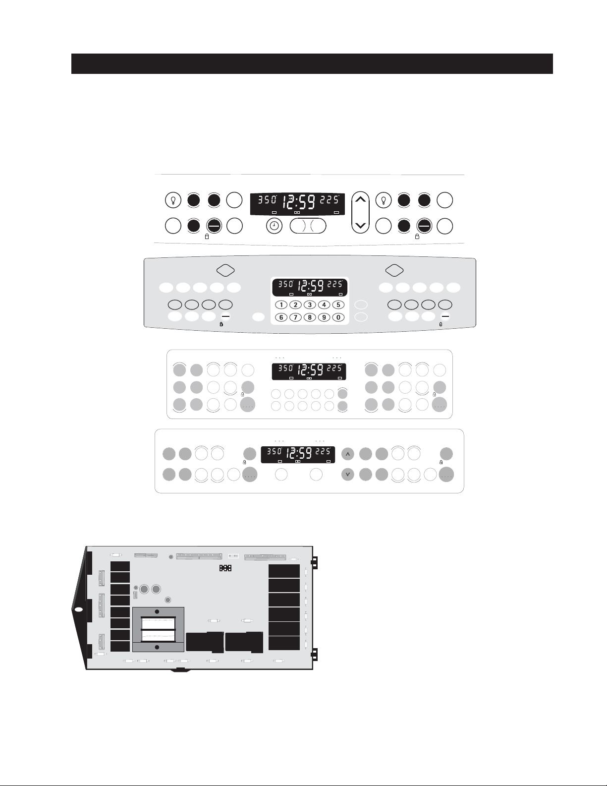
ELECTRONIC OVEN CONTROL (EOC)
CONV
DELAY
CLEAN
BROIL
TIMED
LOCK
PREBAKE
ON TIMER
CONV
DELAY
CLEAN
BROIL
TIMED
LOCK
PREBAKE
CONV
DELAY
CLEAN
BROIL
TIMED
LOCK
PREBAKE
ONTIMER
CONV
DELAY
CLEAN
BROIL
TIMED
LOCK
PREBAKE
CONV
DELAY
CLEAN
BROIL
TIMED
LOCK
PREBAKE
ONTIMER
CONV
DELAY
CLEAN
BROIL
TIMED
LOCK
PREBAKE
CONV
DELAY
CLEAN
BROIL
TIMED
LOCK
PRE-
BAKE
ONTIMER
CONV
DELAY
CLEAN
BROIL
TIMED
LOCK
PRE-
BAKE
1. The EOC offers Bake, Broil, Preheat (some models), Speed Bake (some models), Convection Bake and Convection
Roasting modes (some models),Timed and Delayed Baking, and Cleaning functions.
2. Convection operates with an element and a fan dedicated to convection (some models).
3. This EOC has a touch sensitive membrane.
4. The EOC includes a display board and a relay board.
NOTE: The EOC is not field repairable. Only temperature settings can be changed. See oven calibration.
NOTE: Appearance may vary depending on model.
Select
Clean
Lower OvenUpper Oven
Speed
bake
Keep
warm
C
ONV
B
AKE
heat
Bake
Broil
S
TART
F
LEX
C
LEAN
O
VEN
L
IGHT
N/OFF
O
Lower Oven
Pre
Speed
clean
Clean
Lower Oven
Bake
Warm&
Hold
C
ONV
R
OAST
Speed
clean
Clea n
Maxx
clean
S
LOW
C
OOK
D
ELAY
S
TART
Bake
time
Start
time
C
3
C
ONV
ONVERT
warm
Broil
STOP
Clear
Oven
Lockout
L
OWEROVEN
W
ARM
H
OLD
O
VENCOOK
T
IME
IMEDOVEN
T
Bake
time
Start
time
Keep
Oven
light
Cook
Time
Delay
Start
B
AKEBROIL
P
RE
&
H
EAT
S
TOP
C
LEAR
VEN
O
L
OCKOUT
Oven
light
Clear
/Off
Controls
START
Clear
/Off
Controls
START
Upper Oven
P
Bake
Warm &
Select
Clean
Hold
U
PPEROVEN
C
ONV
B
AKE
C
ONV
C
ONV
C
ONVERT
R
OAST
F
LEX
S
LOW
C
LEAN
C
OOK
O
VEN
O
D
ELAY
L
IGHT
S
TART
ON/O
FF
3
W
ARM
H
VENCOOK
T
IMEDOVEN
T
STOP
Clear
Oven
Lockout
B
&
OLD
IME
Delay
S
TART
AKEBROIL
P
RE
H
EAT
S
TOP
C
LEAR
VEN
O
L
OCKOUT
Time
Start
Cook
Broil
Upper Oven
Conv
Pre
Speed
Bake
bake
heat
clean
Conv
Bake
Speed
bake
Keep
warm
Clea n
Maxx
Broil
clean
Bake
Speed
time
clean
Start
Clean
time
convert
Conv
roast
Bake
Broil
time
Start
time
Keep
warm
Oven
light
Clear
/Off
Controls
START
Clear
/Off
Controls
Oven
START
light
AM
R
B
PM
CONV
BROIL
PRE-
DELAY
TIMED
BAKE
ON
CLEAN OVEN
CLEAN
LOCK
P
R
B
CONV
BROIL
DELAY
TIMED
CLEAN
LOCK
C
LOCK
Even-Cook Convection Ovens
P
R
B
CONV
BROIL
DELAY
TIMED
CLEAN
LOCK
UPPER OVEN LOWER OVEN
123
6
789
Speed Bake Ovens
P
AM
R
B
PM
CONV
BROIL
PRE-
DELAY
TIMED
BAKE
ON
CLEAN OVEN
CLEAN
LOCK
UPPER OVEN LOWER OVEN
Clock
P
R
B
CONV
BROIL
PRE-
DELAY
TIMED
1
1
Add 1
Minute
2
STOPON TIMER
2
STOPON TIMER
P
R
B
CLEAN
Timer
On/Off
BAKE
ON
CLEAN
LOCK
P
R
B
CONV
BROIL
PRE-
DELAY
TIMED
BAKE
ON
CLEAN
LOCK
ADD1
M
INUTE
K
ITCHEN
T
IMER
N/OFF
O
P
R
B
CONV
BROIL
DELAY
TIMED
BAKE
CLEAN
LOCK
4
5
0
CONV
BROIL
PRE-
DELAY
TIMED
BAKE
ON
LOCK
PRE-
ON
Clock
Timer
Conv
bake
Conv
convert
Conv
roast
On/Off
Bake
Broil
2
1
STOP ON TIMER
Timer
Set/Off
AM
PM
PREBAKE
ON
CLEAN OVEN
AM
PM
PREBAKE
ON
CLEAN OVEN
2
1
STOPON TIMER
Electronic oven control relay board Relay Board Legend:
P19
1
3
P
J1
A
B
C
3
3
P
D
E
F
2
3
P
G
H
P34
P20P21
P28
P26
P25
I
P27
P29
P24
J
P17
P2
P
P3
O
P4
N
P9
M
P10
L
P11
K
P1 P18P23P8P22
A. Lower MDL relay
B. Lower convection fan relay
C. Lower cooling fan relay
D. Upper MDL relay
E. Upper convection fan relay
F. Upper cooling fan relay
G. Upper light relay
H. Lower light relay
I. Lower DLB relay
J. Upper DLB relay
K. Lower convection relay
L. Lower bake relay
This relay serves to energize the upper and lower oven
heating elements, convection and door lock motors, and
oven lamp. It also powers the display board.
M. Lower broil relay
N. Upper convection relay
O. Upper bake relay
P. Upper broil relay
2
ELECTRONIC OVEN CONTROL (continued)
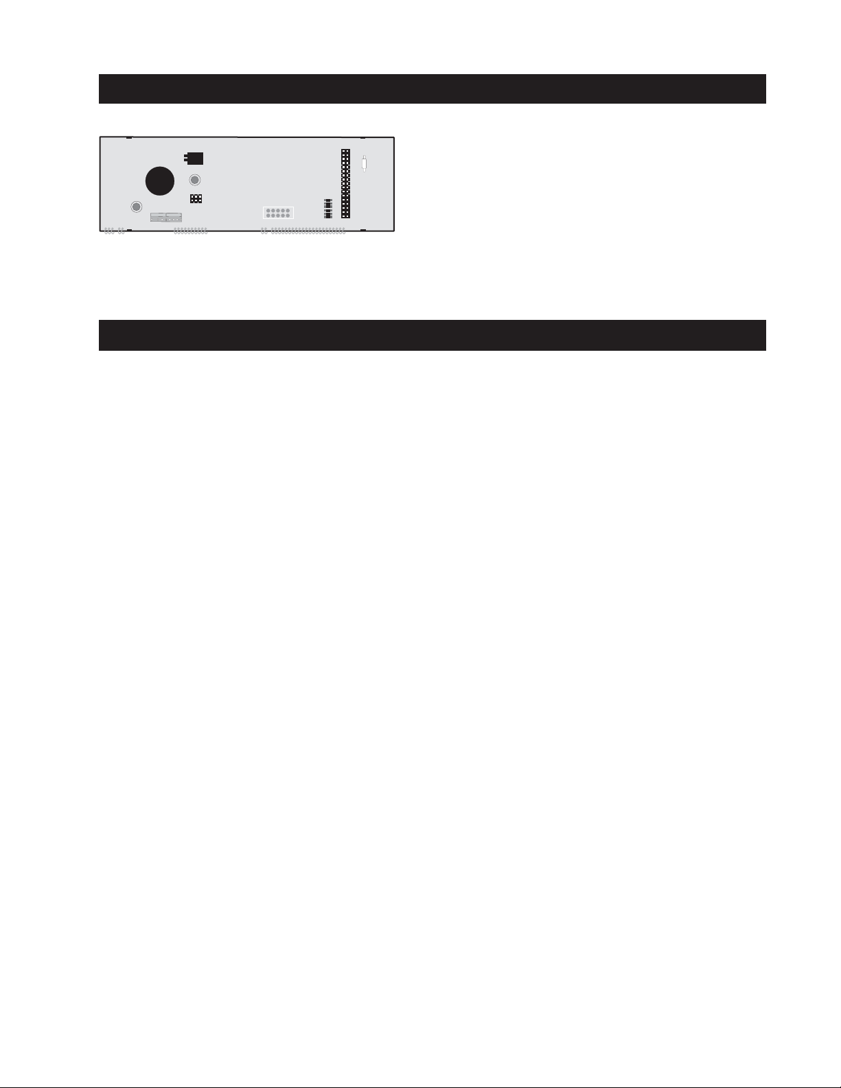
Electronic oven control display board
P3
P8
P4
P1
P2
P1 connector: This 9 pin connector is connected to the relay board.
P3 connector: This 1 or 2 X 17 pin connector is connected to the keyboard.
P4 connector: This 6 pin connector is used for Micro programming.
OVEN ELEMENT - OPERATION
Baking mode -First rise: Bake element is on 40 seconds per minute.
Broil element is on 19 seconds per minute.
-Normal baking: Bake element is on between 40 and 42 seconds per minute.
Broil element is on between 5 and 8 seconds per minute.
Broiling mode Broil element is on for 60 seconds per minute.
Convection mode -First rise: Bake element is on 40 seconds per minute.
Broil element is on 19 seconds per minute.
-Convection baking: Convection element is on for 60 seconds per minute.
Convection Roast -First rise: Bake element is on 40 seconds per minute.
Broil element is on 19 seconds per minute.
-Convection roast: Bake element is on for 50 seconds per minute.
Broil element is on for 9 seconds per minute.
Clean mode: Bake element is on for 60 seconds per minute
and broil element is off.
-Models with hidden Bake element is on for 20 seconds per minute.
bake: Broil element is on for 40 seconds per minute.
NOTE: SELF-CLEANING CYCLE CANNOT BE STARTED IF THE OTHER OVEN IS IN OPERATION, AND
YOU CANNOT OPERATE THE SECOND OVEN IF THE OTHER OVEN IS ON A SELF-CLEANING
CYCLE.
3

TERMINAL BOARD CONNECTORS
P1 & J1 Pin Designations:
KEYBOARD
*Micro
Programming
* Micro Programming
1 - MISO 2 - +5V
3 - SCK 4 - MOSI
5 - Reset 6 - GND
P3 (2x17 pins)
P4 (6 pins)
Display
Board
Flash
and
eeprom
Display Beeper
1- Filament 1
2- Filament 2
3- Ground
4- Vdisp
P1 (9 pins) J1 (9 pins)
Door 1 Position
Door Lock 1 Common
Door 1 Unlock
Door 2 Position
Door Lock 2 Common
Door 2 Unlock
5- RS485 Comm1
6- Rs485 Comm2
7- +12V
8- Not used
9- Second PB
*Micro
Programming
Door 1 Lock
RTD 1
RTD Common 1
Door 2 Lock
RTD 2
RTD Common 2
P29 (6)
P27-5
P27-3
P27-6
P27-7
P27-9
P27-10
P28-4
P28-3
P28-6
P28-7
P28-8
P28-9
N
P23
Power
Board
Flash
DLB
K1
DLB
K8
P22
P20
P25
P8
L
1
P24
P1
P21
P33-7
P31-4
L1 L1
P32-1
OR P34
P2
P3
P4
P17
P32-3
P33-1
P33-2
P9
P10
P11
P18
P33-4
P31-1
P31-2
Upper MDL (K13)
Lower MDL (K16)
P33-5 OR P19
Upper Broil
(K2)
Upper Bake
(K3)
Upper Conv Ring
(K4)
Lower Light
(K5)
Upper Light
(K6)
Upper Cooling Fan
(K7)
Lower Broil
(K9)
Lower Bake
(K10)
Lower Conv Ring
(K11)
Upper Conv Fan
(K12)
Lower Cooling Fan
(K14)
Lower Conv Fan
(K15)
N
L 2
L 1
4
ELECTRONIC OVEN CONTROL (FAULT CODES)
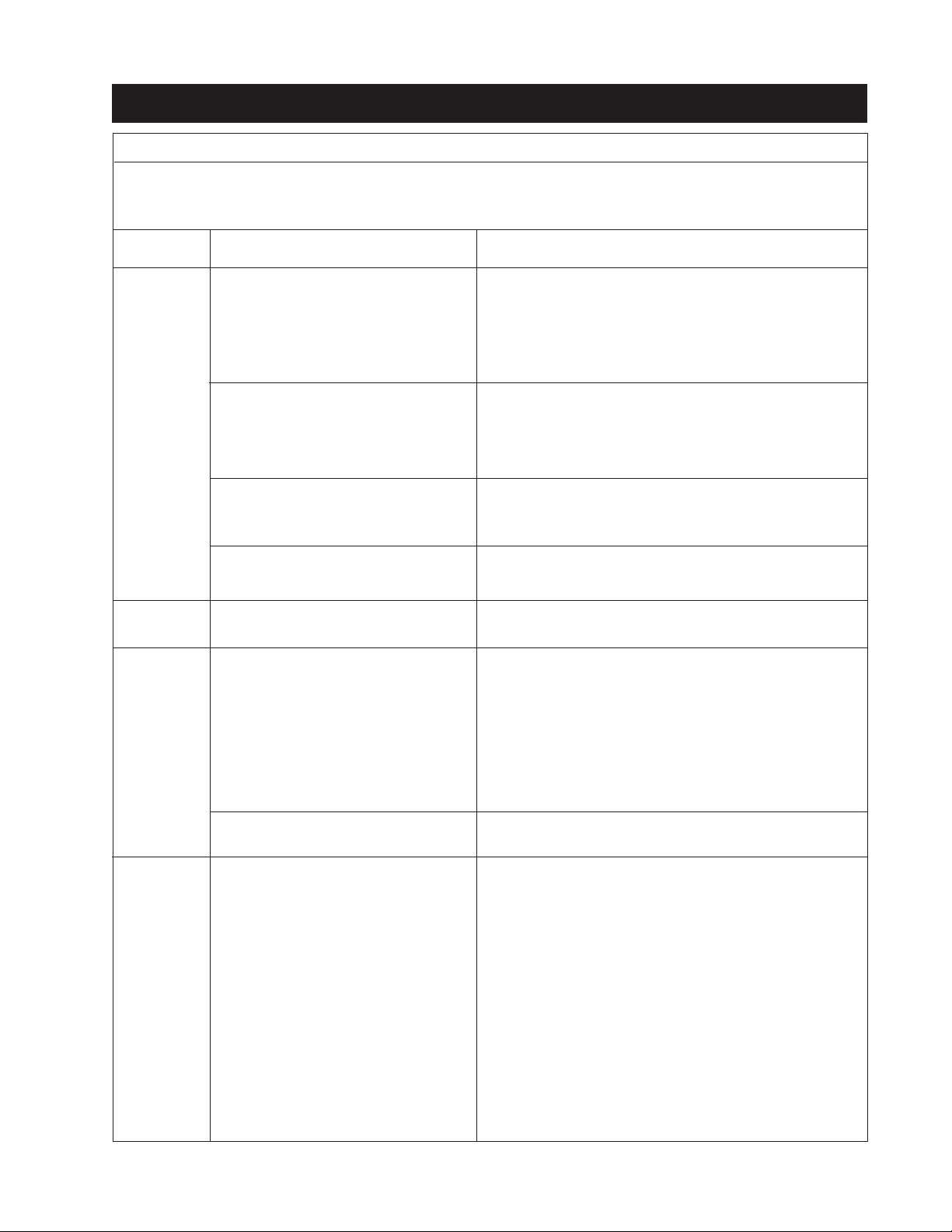
ELECTRONIC OVEN CONTROL (EOC) FAULT CODE DESCRIPTIONS
Note: Only four fault codes series are displayed by this control “F1”, "F2", "F3" and “F9”. Generally speaking “F1” implies
a control failure, “F2” a bad communication between display board and relay board, “F3” an oven probe problem, and “F9”
a latch motor problem.
Fault Code
Series
F1
Likely Failure Condition/Cause
(F10) Control has sensed a potential
runaway oven condition. Control
may have shorted relay, RTD sensor
probe may have a gone bad.
Suggested Corrective Action
Press Clear or Cancel key.
Check RTD sensor probe and replace if necessary. If oven is
overheating, disconnect power. If oven continues to oveheat
when power is reapplied, replace EOC. Severe overheating may
require the entire oven to be replaced, should damage be
extensive.
F2
F3
F9
(F11) Shorted Key: a key has been
detected as pressed (for more than
the debounce period) will be
considered a shorted key alarm
and will terminate all oven activity.
(F13) Control's internal checksum may
have become corrupted.
(F14) Relay watchdog failure.
(F20) Bad communication between
display board and relay board.
(F30) Open RTD sensor probe/ wiring
problem. Note: EOC may initially
display an "F10", thinking a
runaway condition exists.
(F31) Shorted RTD sensor probe / wiring
problem. Note: "F31" is displayed
when oven is in active mode or an
attempt to enter an active mode is
made.
(F32) Key loop is detected as an open
cicuit.
(F90 Door motor mechanism failure.
and
F95)
Press Clear or Cancel key.
Press Clear or Cancel key.
Disconnect power, wait 30 seconds ad reapply power. If fault
returns upon power-up, replace EOC.
Press Clear or Cancel key.
Replace Relay board.
Press Clear or Cancel key.
Verify connections between 2 boards (P1 and J1).
Press Clear or Cancel key.
Check wiring in probe circuit for possible open condition.
Check RTD resistance at room temperature (compare to probe
resistance chart). If resistance does not match the chart, replace
the RTD sensor probe.
Let the oven cool down and restart the function
Press Clear or Cancel key.
Verify if the the keyboard is connected (P3).
Press CLEAR key.
If CLEAR key does not eliminate problem, turn off power for
30 seconds, then turn on power.
Check wiring of Lock Motor, and Lock Switch and Door Switch
circuits.
Unplug the lock motor from the board and apply power (L1)
directly to the Lock Motor. If the motor does not rotate, replace
Lock Motor Assembly.
Check Lock Switch A for proper operation (do they open and
close, check with ohmmeter). The Lock Motor may be powered
as in above step to open and close Lock Switch. If the Lock
Switch is defective, replace Motor Lock Assembly.
If all above steps fail to correct situation, replace EOC.
5
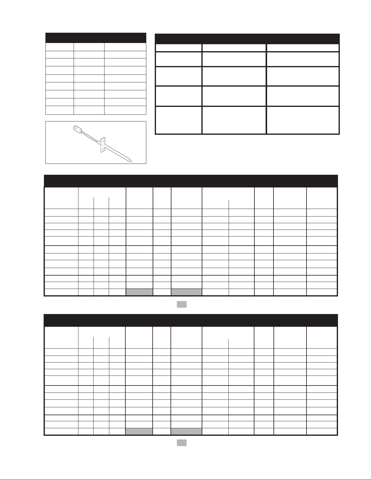
RTD SCALE
Temp. °F Temp. °C Resistance (ohms)
32 ± 1.9 0.0 ± 1.1 1000 ± 4.0
75 ± 2.5 23.9 ± 1.4 1091 ± 5.3
250 ± 4.4 121.1 ± 2.4 1453 ± 8.9
350 ± 5.4 176.7 ± 3.0 1654 ± 10.8
450 ± 6.9 232.2 ± 3.8 1852 ± 13.5
550 ± 8.2 287.8 ± 4.6 2047 ± 15.8
650 ± 9.6 343.3 ± 5.3 2237 ± 18.5
900 ± 13.6 482.2 ± 7.6 2697 ± 24.4
OVEN
TEMPERATURE
SENSOR
UPPER OVEN CIRCUIT ANALYSIS MATRIX
ELEMENTS
Bake
Broil
Conv. Bake
Conv. Roast
Clean
Locking
Locked
Unlocking
Unlocked
Light
Door Open
Door Closed
Bake
P3
X
X
X
X
Broil
P2
X*
X
X*
Conv.
P4
X
Conv.Fan
P33-4
ELECTRICAL RATING
27" 30"
KW rating
240/208 8.2/6.2 8.2/6.2
Bake Element Vary depending on model:
Wattage 2300W/17820W or 3400W/2554W
Broil Element 3400W/2554W Vary depending on model:
Wattage 2750W/2065W or
Convection Vary depending on model: Vary depending on model:
Element No convection element No convection element
Wattage or 350W element or 350W element
Light
Door Motor
P33-1
X
X
X
X
P33-7
X
X
2700W/2028W
Lock Motor Switches
P27-3
&
P27-7
NC
NO
NO
NC
P27-3
A
&
P27-6
NO
NC
NC
NO
DLB
L2 out
P24
X
X
X
X
X
4000W/3004W
2500W element
Door Switch
P27-5 / P27-3
COM-NO
X
Cooling
Fan
P33-2
Low Speed
Low Speed
Low Speed
Low Speed
Low & High
Speed
* Denotes Top heat Relay will operate in this condition only
LOWER OVEN CIRCUIT ANALYSIS MATRIX
ELEMENTS
Light
Door Motor
P32-3
X
X
P31-4
X
Bake
Broil
Conv. Bake
Conv. Roast
Clean
Locking
Bake
P10
X
X
X
X
Broil
P9
X*
X
X*
Conv.
P11
X
Conv.Fan
P31-2
Locked
Unlocking
X
Unlocked
Light
Door Open
X
X
Door Closed
* Denotes Top heat Relay will operate in this condition only
Lock Motor Switches
P28-3
&
P28-7
NC
NO
NO
NC
6
Door Switch
P28-3
A
&
P28-6
NO
NC
NC
NO
DLB
L2 out
P25
X
X
X
X
X
P28-3 / P28-4
COM-NO
X
Cooling
Fan
P31-1
Low Speed
Low Speed
Low Speed
Low Speed
Low & High
Speed
 Loading...