

Page 1

SERVICE DATA SHEET 318047301 (9704) Rev. C
Electric Double Wall Ovens with Electronic Oven Control (Robertshaw 5800 - 318010501)
NOTICE
This service data sheet is intended for use by persons having electrical and mechanical training and a
level of knowledge of these subjects generally considered acceptable in the appliance repair trade.
The manufacturer cannot be responsible, nor assume any liability, for injury or damage of any
kind arising from the use of this data sheet.
SAFE SERVICING PRACTICES
To avoid the possibility of personal injury and/or property damage, it is important that safe servicing
practices be observed. The following are some limited examples of safe practices.
1. Do not attempt a product repair if you have any doubts as to your ability to complete it in a safe
and satisfactory manner.
2. Before servicing or moving an appliance, remove power cord from electric outlet, trip circuit
breaker to Off, or remove fuse.
3. Never interfere with the proper installation of any safety device.
4. USE ONLY REPLACEMENT PARTS CATALOGED FOR THIS APPLIANCE. SUBSTITUTIONS
MAY DEFEAT COMPLIANCE WITH SAFETY STANDARDS SET FOR HOME APPLIANCES.
5. GROUNDING: The standard color coding for safety ground wires is GREEN OR GREEN WITH
YELLOW STRIPES. Ground leads are not to be used as current carrying conductors. IT IS
EXTREMELY IMPORTANT THAT THE SERVICE TECHNICIAN REESTABLISH ALL SAFETY
GROUNDS PRIOR TO COMPLETION OF SERVICE. FAILURE TO DO SO WILL CREATE A
POTENTIAL HAZARD.
6. Prior to returning the product to service, ensure that:
• All electric connections are correct and secure.
• All electrical leads are properly dressed and secured away from sharp edges, high-temperature
components, and moving parts.
• All uninsulated electrical terminals, connectors, heaters, etc. are adequately spaced away from
all metal parts and panels.
• All safety grounds (both internal and external) are correctly and securely reassembled.
• All panels are properly and securely reassembled.
1
Page 2
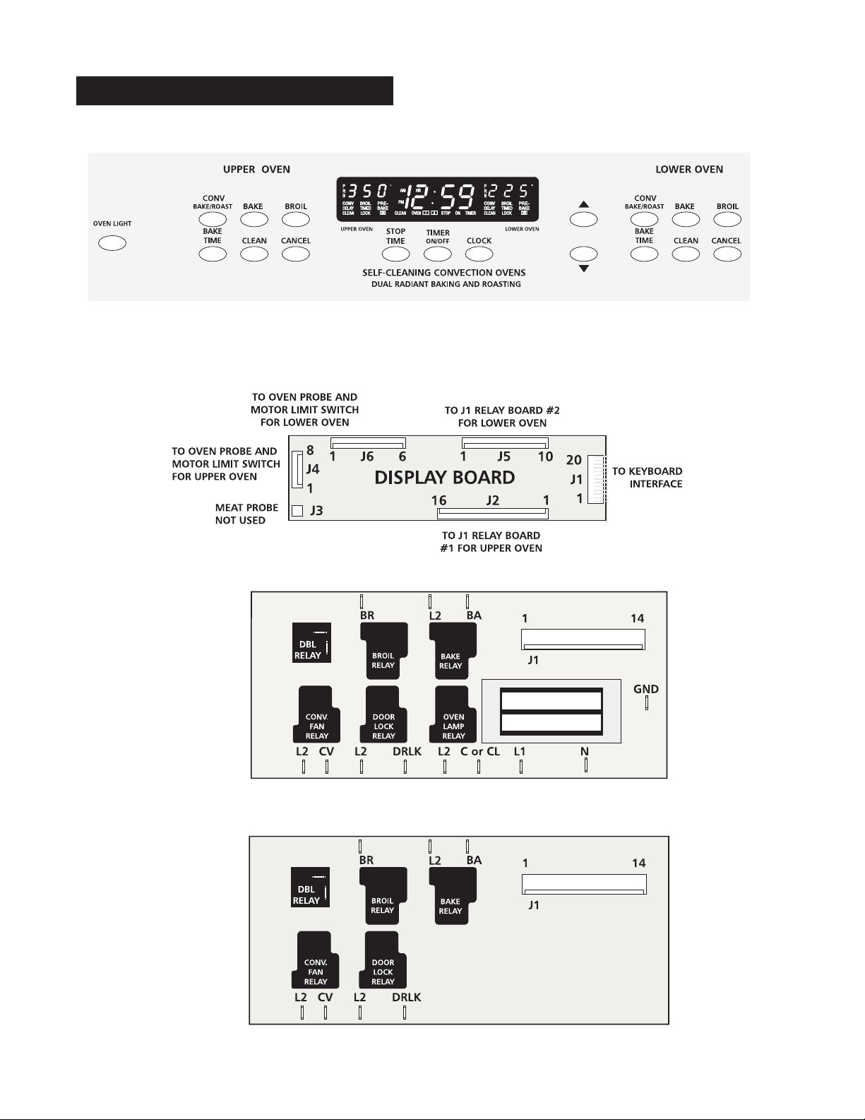
ELECTRONIC OVEN CONTROL
* Depending on model, shape of buttons or pads may vary.
RELAY BOARD #1
FOR UPPER OVEN.
RELAY BOARD # 2
FOR LOWER OVEN
TRANSFORMER
2
Page 3

ELECTRONIC OVEN CONTROL FOR DOUBLE WALL OVENS
The electronic oven control includes:
• a display board
• a relay board #1 and transformer for upper oven
• a relay board #2 for lower oven
DISPLAY BOARD UNIT
The display board unit includes 6 connectors (J1 to J6)
J1 connector: This 20 pin connector is connected to the keyboard (touch pads).
J2 connector: This 16 pin connector is connected to J1 in relay board #1 for upper oven. J2
serves to energize the upper oven relays (6 of) and to power the control display.
J3 connector: Unused
J4 connector: This 8 pin connector is connected to the upper oven probe and upper oven motor
limit switch.
J5 connector: This 10 pin connector is connected to J1 in relay board #2 for lower oven. J5 serves
to energize the lower oven relays (5 of).
J6 connector: This 6 pin connector is connected to lower oven probe and lower oven motor limit
switch.
RELAY BOARD #1 FOR UPPER OVEN
This relay board includes 6 relays and a transformer. These relays serve to energize the upper oven
heating elements, convection and door lock motors, and oven lamp. It also powers the display board.
Its 14 pin connector J1 is connected to J2 in the display board.
RELAY BOARD #2 FOR LOWER OVEN
This relay board includes 5 relays. These relays serve to energize the lower oven heating elements,
convection and door lock motors. Its 14 pin connector is connected to J5 in the display board.
OVEN ELEMENT - OPERATION
Baking mode -First rise: Broil element is on 30 seconds per minute.
Bake element is on 60 seconds per minute.
-Normal baking: Broil element is on 7 seconds per minute.
Bake element is on 50 seconds per minute.
Broiling mode Broil element is on for 60 seconds per minute.
Convection mode Bake element is on for 33 seconds per minute.
Broil element is on for 12 seconds per minute.
Clean mode: -First 10 minutes: Broil element is on for 42 seconds per minute
and bake element is off.
-After 10 minutes: Bake element is on for 60 seconds per minute
and broil element is off.
NOTE: SELF CLEANING CYCLE CANNOT BE STARTED IF THE OTHER OVEN IS IN OPERATION, AND
YOU CANNOT OPERATE THE SECOND OVEN IF THE OTHER OVEN IS ON A SELF CLEANING
CYCLE.
3
Page 4

ELECTRONIC OVEN CONTROL (FAULT CODES)
FAILURE MODES
F0 - ALARM (EEPROM OPTION)
This EEPROM selectable option enables the control to recognize a shorted key within approximately
32 seconds. This option has priority over shorted watchdog failure alarm F1.
F1 - ALARM
A failure is detected in the element relay watchdog protection circuits and will activate a "CANCEL"
feature. "F1" will be displayed in the time digits and the alarm will sound until the cancel key for the
oven is pressed or another function is selected.
F2 - ALARM
Occurs when cavity temperature exceeds the clean runaway temp in the clean mode or the cooking
runaway temp in a non-clean condition and will activate a "CANCEL" feature. "F2" will be displayed in
the digits for the affected cavity, and the alarm will sound until the CANCEL key for the oven is pressed
or another function is selected. This failure may be overridden by the F3 or F4 alarm.
F3- ALARM
Occurs when there is a short circuit in the oven temperature sensor for 16 temperature conversions in
a row and will activate a "CANCEL" feature. "F3" will be displayed in the digits for the affected oven
cavity, and the alarm will sound until the CANCEL key for the oven is pressed. The alarm will return in
16 seconds if the failure is still present.
F4 - ALARM
An open circuit in the oven temperature sensor for 16 temperature conversions in a row will activate a
"CANCEL" feature. "F4" will be displayed in the temp digits for the affected cavity, and the alarm will
sound until the CANCEL key for the affected oven is pressed. If the failure is present after cancel is
pressed, the alarm will not be reactivated unless a baking or cleaning function is attempted. The
opposite oven is unaffected with this alarm.
F6 - ALARM
A failure is detected in the EEPROM checksum comparison. This indicates the EEPROM checksum
and the calculated checksum are not the same. Only time of day and timer operation will be allowed in
the control.
F-7 ALARM
A failure detected in the clean lock/phase circuitry for 16 seconds in a row will activate a "CANCEL"
feature. "F7" will be displayed in the temp digits of the affected oven and the alarm will sound until
CANCEL for the affected oven is pressed or another function is selected. This test will be performed
constantly.
F-8 ALARM
Occurs when the door lock runs for 2 minutes without seeing either the lock or phase switch change
positions.
4
Page 5

TERMINAL BOARD CONNECTORS
(French translation included)
5
Page 6

CONVECTION BAKE MODE
The convection oven uses the addition of a fan to move the heated air already in the oven. Moving the
heated air helps to destratify the heat or cause uniform heat distribution. Longer cooking times can be
reduced by as much as 30%. The air is drawn in through a fan shroud located on the rear wall of the
oven. It is then discharged around the outer edges of this shroud. The air is circulated around the food
and then enters the shroud again. As with conventional electric ranges, there is still an oven vent which
discharges through the control panel vent opening.
To set the control in convection mode, follow these two steps:
1. Press the CONV. BAKE/ROAST pad.
2. Press the UP or DOWN arrow pads to select the desired temperature.
After 3 seconds, the oven will automatically start and the fan will begin to run. To cancel the convection
baking function, press the CANCEL pad.
NOTE: THE FAN RUNS CONTINUOUSLY WHILE IN THE CONVECTION MODE. THE FAN WILL
STOP IF THE DOOR IS OPENED WHILE CONVECTION BAKING/ROASTING. THE
HEATING ELEMENTS WILL CONTINUE TO OPERATE WITH THE DOOR OPEN.
CONVECTION MODE OVEN TEMPERATURES
Because heat is more evenly distributed during convection temperatures, foods can be cooked at lower
temperatures. In order to allow the consumer to bake per their existing methods using regular baking
recipes, there is an offset temperature of -25°F in the programming of the control. This means that when
the consumer sets the control for 375°F, the actual oven temperature is cycling at 350°F.
6
Page 7

CONVECTION CYCLING
When the control is set to the CONV. BAKE/ROAST function, the fan immediately comes on. The broil
and bake elements are energized for the first 12 seconds of every minute. For the next 21 seconds, only
the bake element is energized. Both elements are off the remaining 27 seconds. This cycle is repeated
for the duration of the cooking period.
Convection Cycle
NORMAL BAKE MODE
1
3
OFF
BAKE
1 = Broil & Bake 12 sec/min
2 = Bake 21 sec/min
3 = Both off 27 sec/min
Approximate Times
BAKE &
BROIL
BROIL
BAKE
OFF
2
During a normal bake mode, the oven uses top heat by cycling the broil element on for 7 seconds each
minute. Both elements use full power when they are on.
FAN RELAY
The fan motor runs continuously while in the convection mode unless the door is opened. If the fan does
not operate, check the following:
• Display illuminated on the electronic control.
• Voltage output between terminals L2 and CV on appropriate board.
• 240 Volts available at fan motor.
• Fan motor coil resistance 56.5 ohms ± 10%.
• Voltage input to fan relay coil during convection bake with door closed.
• Door/light switch.
7
Page 8

ADJUSTING OVEN TEMPERATURE
1. Push the BAKE pad.
2. Set the temperature to 550°F/288°C by pushing the UP arrow pad.
3. Within 2 seconds, push and hold the BAKE pad for approximately 5 seconds until the special 2
digit display appears. Release the BAKE pad.
The display now indicates the difference in degrees between the original factory temperature
setting and the current temperature setting. If the oven control has the original factory calibration,
the display will read "00".
4. The temperature can now be adjusted up or down 35°F/17°C, in 5°F/2.5°C increments, by pushing
the UP or Down arrow pads. Adjust the UP/DOWN arrow pads until the desired amount of offset
appears in the display. A minus sign (-) will appear before the number to indicate the oven will be
cooler by the displayed amount of degrees.
5. When you have made the desired adjustment, push the CANCEL pad to go back to the time of
day display.
NOTE:
CHANGING CALIBRATION EFFECTS BOTH CONVENTIONAL AND CONVECTION MODES.
FAN BLADE
The fan blade is mounted in the rear of the unit and has a "D" shaped opening. Only minimum clearance
exists between the oven back, fan blade, and fan shroud. Be careful not to bend blade when removing
or installing.
Access to the fan blade is gained by removing the fan shroud, held in place by three screws, from the
inside of the oven.
The fan blade is held in place with a hex nut that has left handed threads. When
removing this nut, gently hold the fan blade, and turn the nut clockwise. If one of the
blades becomes deformed, it may be bent back into shape using a flat surface as a
reference.
NOTE: IF THE FAN BLADE IS BENT AND MOTOR VIBRATIONS
INCREASE, THE NOISE MADE BY THE FAN WILL BE
GREATER.
8
Page 9

ELECTRICAL SPECIFICATIONS
ELECTRICAL RATING
30”
KW rating
240/208
Bale Element
Wattage
27”
8.2/6.2 9.0/6.8
2300W/1728W 3000W/2254W
Broil Element
Wattage
3400W/2550W 2750W/2065W
LOWER OVEN LIGHT SWITCH LOCATION /REMOVAL (Some Models)
On some double wall ovens, the light
switch for the lower oven is located on
the lower right-hand side of the oven. The
servicer must pull the oven out of the
cabinet to access it.
Removal/Replacement Procedure
1. Pull wall oven out from cabinet. (Light
switch access is on lower right-hand
side of wall oven.)
2. Remove screw securing cover plate to
side panel.
3. Remove two screws securing light
switch to oven insulation cover.
4. Gently pull switch out of opening to
access and remove wire leads.
5. Reverse procedure to replace switch.
9
Page 10

NOTES
SCHEMATIC DIAGRAM
10
Page 11

NOTES
11
Page 12

12
 Loading...