

Page 1
Installation
Instructions
Instrucciones
para la
instalad6n
Contents
SUBJECT PAGE
Pre-lnstallation Requirements .................................... 2
Electrical Requirements ........................................... 2
Exhaust System Requirements ............................ 2-3
Gas Supply Requirements ....................................... 3
Location of Your Dryer. ............................................ 4
Rough-In Dimensions ............................................. 5
Unpacking ................................................................ 5
Reversing Door Swing .............................................. 5
Electrical Installation ................................................ 6
Grounding Requirements ....................................... 6
Electrical Connections--3-wire .............................. 6
Electrical Connections--4-wire ........................... 6-7
Installation ................................................................ 7
Replacement Parts................................................... 7
Lint Blade Retaining Pin Location ........................... 7
Warranty. ................................................................... 8
Espanol ................................................................ 9-16
Requerimientos de instalacion preliminares .......... 9
Requerimientos electricos ....................................... 9
Requerimientos del sistema de escape ............ 9-10
Requerimientos del suministro de gas ............... 10
Ubicacion de su secadora ...................................... 11
Dimensiones para la instalacion .......................... 12
Desembalaje ........................................................... 12
Puerta reversible .................................................... 12
Instalacion electrica ............................................... 13
Requerimientos para la puesta a tierra ............... 13
Conexiones electricas - trifilares .......................... 13
Conexi6nes electricas - tetrafilares ................. 13-14
Instalaci6n .............................................................. 14
Piezas de recambio ................................................ 14
Garantia ................................................................. 15
Before beginning installation, carefully read these instructions. This
will simplify the installation and ensure the dryer is installed correctly
and safely. Leave these instructions near the Dryer after installation
for future reference.
NOTE: The electrical service to the Dryer must conform with local
codes and ordinances and the latest edition of the National Electrical
Code, ANSI/NFPA 70.
NOTE: The gas service to the Dryer must conform with local codes and
ordinances and the latest edition of the National Fuel Gas Code ANSI
Z223.1.
NOTE: The Dryer is designed under ANSI Z 21.S. 1 - for HOME USE only.
This Dryer is not recommended for commercial applications such as
restaurants or beauty salons, etc.
Antes de comenzar la instalaci6n, lea cuidadosamente estas
instrucciones. Esto simplificara la instalaci6n y aseg urara que la secadora
se instale correctamente y de manera segura. Despu_s de completar la
instalaci6n, coloque estas instrucciones cerca de la secadora para
referencia futura.
NO TA: La alimentacion el_ctrica para la secadora debera cumplir con los
c6digos y reg lamen tos locales y con la ultima edicion del C6digo Electrico
NacionaL
NO TA: La alimentacion de gas para la secadora debera cumplir con los
codigos y reglamen tos locales y con la ultima edicibn del C6digo National
para Gases Combustibles.
NO TA: La secadora esta clasificada para USO DOMES TICO solamente,
de acuerdo con la norma ANSI Z21.5. I o ANSI/UL 2158 - {las ultimas
edidbnes). Esta secadora no se recomienda para uso commercial tal
como en restaurantes, salones de belleza, etc.
For your safety the information in this manual must be followed
to minimize the risk of fire or explosion or to prevent property damage,
personal injury or loss of life.
Do not store or use gasoline or other flammable vapors and liquid in the
vicinity of this or any other appliance.
- WHAT TO DO IF YOU SMELL GAS
Do not try to Nght any appliance.
Do not touch any electrical switch; do not use any phone in your
building.
Clear the room, building or area of all occupants.
Immediately call your gas supplier from a neighbor's phone. Follow
the gas supplier's instructions.
If you cannot reach your gas supplier, call the fire department.
Installations must be performed by a qualified or licensed contractor,
plumber, or gasfitter qualified or licensed by the state, province, or region
where this appliance is being installed.
este manual a fin de reducir a un minimo los riesgos de incendio o explosion
o para evitar danos materiales, lesiones personales o la muerte.
No almacene ni utilice gasolina u otros vapores y Nquidos inflamables en
la proximidad de este o de cualquier otro artefacto electrico.
QUE DEBE HACER S! PERCIBE OLOR A GAS
No trate de encender ningun artefacto electrico.
No toque ningun interruptor electrico; no use ningun telefono en su
edificio.
Haga salir atodos losocupantes de la habitacion, del edificio ydel lugar.
Llame a su proveedor de gas desde el telefono de un vecino. Siga las
instrucciones del proveedor de gas.
Si no Iogra comunicarse con su proveedor de gas, Ilame al
departamento de bomberos.
Lainstalacion y el servicio de mantenimiento debe de realizarlos un instalador
calificado, la agenda de servicios o el proveedor de gas.
Para su seguridad, siga las instrucciones contenidas en
Printed in U.S.A.
P/N 134589900A (0601)
Page 2
PRE-INSTALLA TION REQUIREMENTS
Tools and Materials Required for Installation:
1. Phillips head screwdriver.
2. Channel-lock adjustable pliers.
3. Carpenter's level.
4. Flat or straight blade screwdriver.
5. Duct tape.
6. Rigid or flexible metal 4 inch (10.2 cm) duct.
7. Vent hood.
8. Pipe thread sealer (Gas).
9. Plastic knife.
ELECTRICAL REQUIREMENTS
ELECTR/CDryer I
CIRCUIT- Individual 30 amp. branch circuit fused with 30 amp.
minimum time delay fuses or circuit breakers.
POWER SUPPLY - 3 wire, 240 volt, single phase, 60 Hz,
Alternating Current.
POWER SUPPLY CORD KIT - The dryer MUST employ a 3-
conductor power supply cord NEMA 10-30 type SRDTrated at
240 volt AC minimum, 30 amp., with 3 open end spade lug
connectors with upturned ends or closed loop connectors and
marked for usewith clothes dryers. If being installed in a new
branch circuit installation, manufactured (mobile) home,
recreational vehicle or area which prohibits grounding through
the neutral conductor, the dryer MUST employ a4-conductor
power supply cord NEMA 14-30 type SRDTor ST (asrequired)
rated at 240 volt AC minimum, 30 amp., with 4 open end
spade lug connectors with upturned ends or closed loop
connectors and marked for use with clothes dryers. See
ELECTRICALCONNECTIONSFORA 4-WIRE SYSTEM.
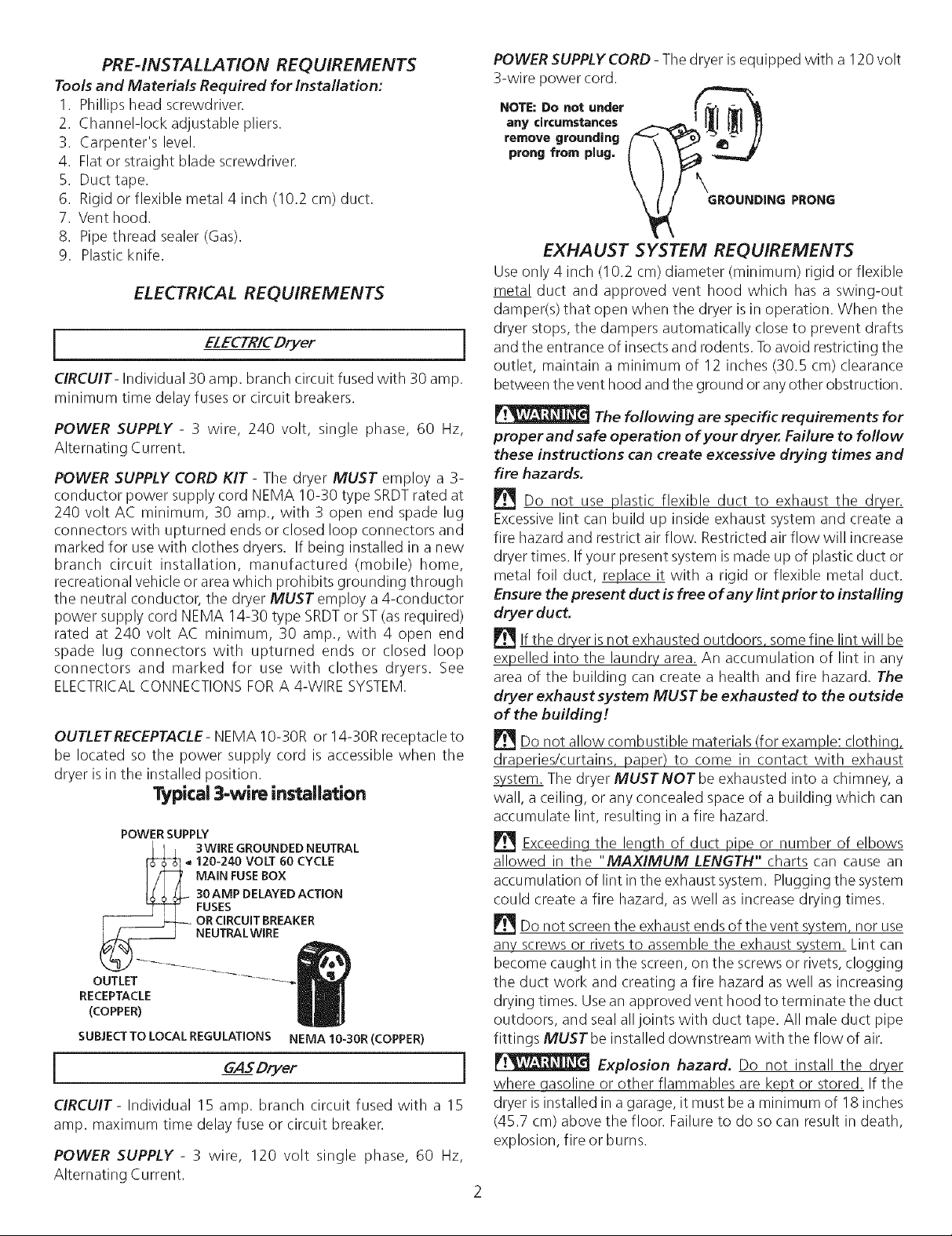
OUTLET RECEPTACLE- NEMA 10-30R or 14-30R receptacle to
be located so the power supply cord is accessible when the
dryer isinthe installed position.
Typical 3-wire ins_ilation
POWER SUPPLY
I I E 3WIRE GROUNDED NEUTRAL
[$-_ 120-240 VOLT 60 CYCLE
I/4 MAI.FUSEBOX
j_ _ _ 30AMPDELAYEDACTION
FUSES
[ _ ORCIRCUITBREAKER
_ NEUTRALWIRE
OUTLET -- _
RECEPTACLE
(COPPER)
SUBJECTTO LOCALREGULATIONS NEMA 10-30R(COPPER)
GAS Dryer i
CIRCUIT- Individual 15 amp. branch circuit fused with a 15
amp. maximum time delay fuse or circuit breaker.
POWER SUPPLY - 3 wire, 120 volt single phase, 60 Hz,
Alternating Current.
POWER SUPPLYCORD - The dryer is equipped with a 120 volt
3-wire power cord.
NOTE: Do not under _'_ -_-,'_
any circumstances |
prong from plug.
remove grounding Q
_ GROUNDING PRONG
EXHAUST SYSTEM REQUIREMENTS
Useonly 4 inch (10.2 cm) diameter (minimum) rigid or flexible
metal duct and approved vent hood which has a swing-out
damper(s) that open when the dryer is in operation. When the
dryer stops, the dampers automatically close to prevent drafts
and the entrance of insectsand rodents. Toavoid restricting the
outlet, maintain a minimum of 12 inches (30.5 cm) clearance
between the vent hood and the ground or any other obstruction.
The following are specific requirements for
proper and safe operation of your dryer. Failure to follow
these instructions can create excessive drying times and
fire hazards.
Do not use plastic flexible duct to exhaust the dryer.
Excessivelint can build up inside exhaust system and create a
fire hazard and restrict air flow. Restricted air flow will increase
dryer times. If your present system ismade up of plastic duct or
metal foil duct, _lace it with a rigid or flexible metal duct.
Ensure the present duct is free of any lint prior to installing
dryer duct,
Ifthe dryer isnot exhausted outdoors some fine lint will be
expelled into the laundry area. An accumulation of lint in any
area of the building can create a health and fire hazard. The
dryer exhaust system MUST be exhausted to the outside
of the building!
Do not allow combustible materials (for example: clothing,
draperies/curtains, paper) to come in contact with exhaust
system. The dryer MUSTNOT beexhausted into a chimney, a
wall, a ceiling, or any concealed space of a building which can
accumulate lint, resulting in a fire hazard.
Exceeding the length of duct pipe or number of elbows
allowed in the "MAXIMUM LENGTH" charts can cause an
accumulation of lint inthe exhaust system. Plugging the system
could create a fire hazard, as well as increase drying times.
_Do not screenthe exhaust endsof the vent system, nor use
any screws or rivets to assemble the exhaust system. Lint can
become caught in the screen, on the screws or rivets, clogging
the duct work and creating a fire hazard as well as increasing
drying times. Use an approved vent hood to terminate the duct
outdoors, and seal all joints with duct tape. All male duct pipe
fittings MUST be installed downstream with the flow of air.
Explosion hazard. Do not install the dryer
where qasoline or other flammables are kept or stored. If the
dryer isinstalled in a garage, it must be a minimum of 18inches
(45.7 cm) above the floor. Failure to do so can result in death,
explosion, fire or burns.
Page 3
Number
of
90°
Turns
0
I
2
3
4
Number
of
90°
Turns
0
1
2
3
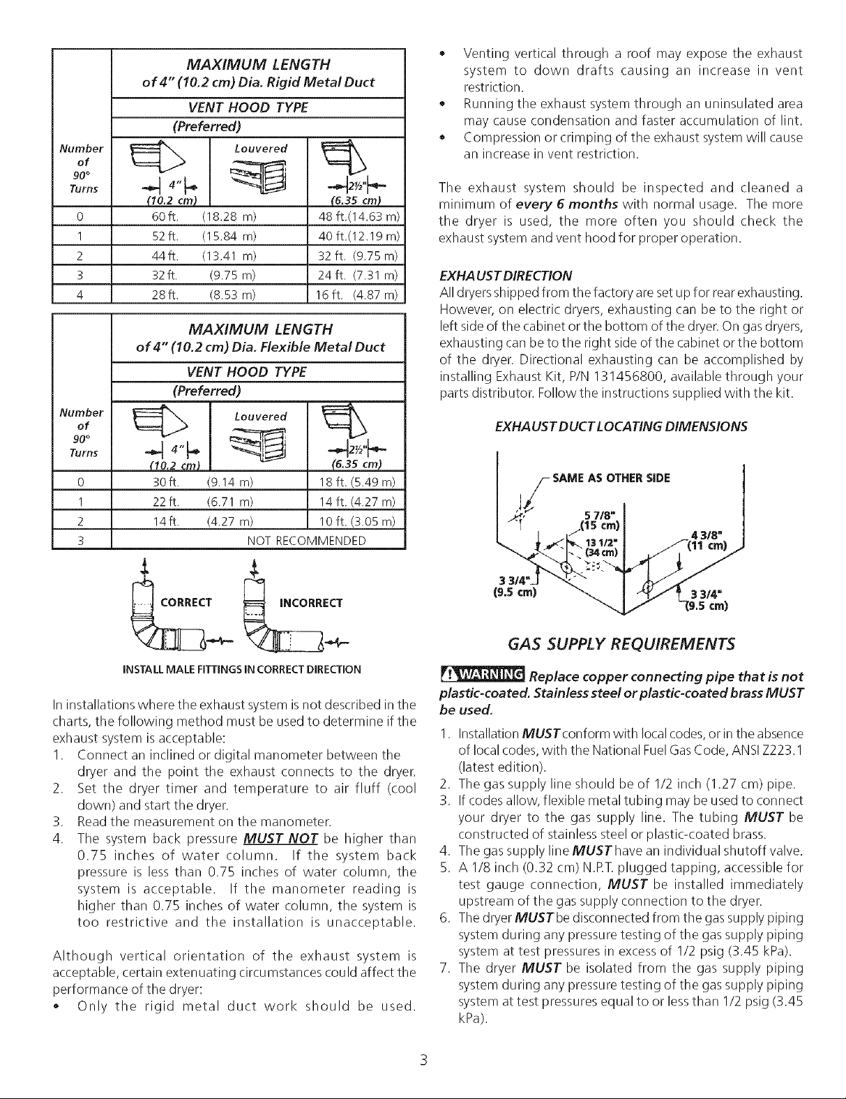
MAXIMUM LENGTH
of 4" (10.2 cm) Dia. Rigid Metal Duct
VENT HOOD TYPE
(Preferred)
Louvered
(10.2 cm)
60ft,
52ft.
44 ft.
32ft.
28ft.
(18.28 rn)
(15.84 m)
(13.41 m)
(9.75 m)
(8.53 m)
(6.35 cm_
48 ft.(14.63 m)
40 ft.(12.19 m)
32 ft. (9.75 m)
24ft. (7.31 m)
16ft. (4.87 m)
MAXIMUM LENGTH
of 4" (10.2 cm) Dia. Flexible Metal Duct
VENT HOOD TYPE
(Preferred)
Louvered
(10.2 cm)
30ft.
22ft.
14ft.
(9.14
m) 18 ft. (5.49 m)
(6.71
m) 14ft. (4.27 m)
(4.27
m) 10ft. (3.05 m)
16.35cm)
NOT RECOMMENDED
Venting vertical through a roof may expose the exhaust
system to down drafts causing an increase in vent
restriction.
Running the exhaust system through an uninsulated area
may cause condensation and faster accumulation of lint.
Compression or crimping of the exhaust system will cause
an increase in vent restriction.
The exhaust system should be inspected and cleaned a
minimum of every 6 months with normal usage. The more
the dryer is used, the more often you should check the
exhaust system and vent hood for proper operation.
EXHAUSTDIRECTION
All dryers shipped from the factory are set up for rearexhausting.
However, on electric dryers, exhausting can be to the right or
left side of the cabinet or the bottom of the dryer.On gasdryers,
exhausting can be to the right side of the cabinet or the bottom
of the dryer. Directional exhausting can be accomplished by
installing Exhaust Kit, P/N 131456800, available through your
parts distributor. Follow the instructions supplied with the kit.
EXHAUST DUCT LOCATING DIMENSIONS
INSTALL MALE FITTINGS IN CORRECT DIRECTION
Ininstallations where the exhaust system isnot described in the
charts, the following method must be used to determine if the
exhaust system is acceptable:
1. Connect an inclined or digital manometer between the
dryer and the point the exhaust connects to the dryer.
2. Set the dryer timer and temperature to air fluff (cool
down) and start the dryer.
3. Read the measurement on the manometer.
4. The system back pressure MUST NOT be higher than
0.75 inches of water column. If the system back
pressure is less than 0.75 inches of water column, the
system is acceptable. If the manometer reading is
higher than 0.75 inches of water column, the system is
too restrictive and the installation is unacceptable.
Although vertical orientation of the exhaust system is
acceptable, certain extenuating circumstances could affect the
performance of the dryer:
• Only the rigid metal duct work should be used.
3
(9.5 cm)
GAS SUPPLY REQUIREMENTS
Replace copper connecting pipe that is not
plastic-coated. Stainless steel or plastic-coated brass MUST
be used.
I. Installation MUSTconform with localcodes,or in the absence
of local codes,with the National Fuel GasCode, ANSIZ223. I
(latest edition).
2. The gas supply line should be of 1/2 inch (1.27 cm) pipe.
3. If codes allow, flexible metal tubing may be used to connect
your dryer to the gas supply line. The tubing MUST be
constructed of stainless steel or plastic-coated brass.
4. The gas supply line MUST have an individual shutoff valve.
5. A 1/8 inch (0.32 cm) N.RT.plugged tapping, accessible for
test gauge connection, MUST be installed immediately
upstream of the gas supply connection to the dryer.
6. The dryerMUSTbe disconnected from the gassupply piping
system during any pressure testing of the gassupply piping
system at test pressures in excess of 1/2 psig (3.45 kPa).
7. The dryer MUST be isolated from the gas supply piping
system during any pressure testing of the gassupply piping
system at test pressures equal to or lessthan 1/2 psig (3.45
kPa).
Page 4
LOCATION OF YOUR DRYER
DO NOT INSTALL YOUR DRYER:
1. In an area exposed to dripping water or outside weather
conditions.
2. In an area where it will come in contact with curtains, drapes,
or anything that will obstruct the flow of combustion and
ventilation air.
3. On carpet. Floor MUST be solid with a maximum slope of 1
inch (2.54 cm).
INSTALLATION IN RECESSOR CLOSET
1. A dryer installed ina bedroom, bathroom, recessor closet,
MUSTbe exhausted outdoors.
2. No other fuel burning appliance shall be installed in the
same closet asthe Gas dryer.
3. Your dryer needsthe spacearound it for proper ventilation.
DO NOT INSTALL YOUR DRYER IN A CLOSET WITH A
SOLID DOOR.
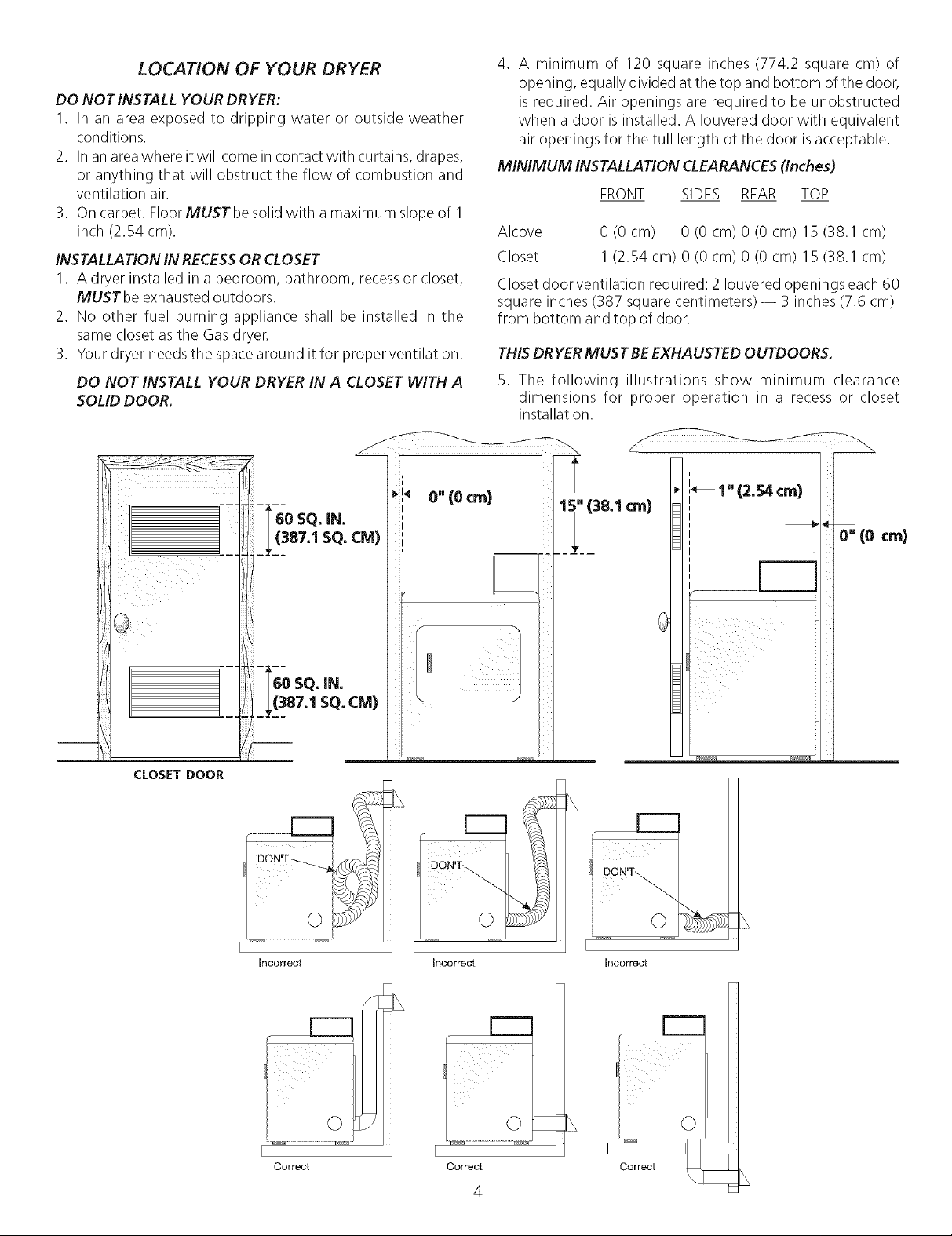
4. A minimum of 120 square inches (774.2 square cm) of
opening, equally divided at the top and bottom of the door,
is required. Air openings are required to be unobstructed
when a door is installed. A Iouvered door with equivalent
air openings for the full length of the door isacceptable.
MINIMUM INSTALLATION CLEARANCES (Inches)
FRONT SIDES REAR TOP
Alcove 0 (0 cm) 0 (0 cm) 0 (0 cm) 15 (38.1 cm)
Closet I (2.54 cm) 0 (0 cm) 0 (0 cm) 15 (38.1 cm)
Closet door ventilation required: 2 Iouvered openings each 60
square inches (387 square centimeters) -- 3 inches (7.6 cm)
from bottom and top of door.
THISDRYERMUST BE EXHAUSTED OUTDOORS.
5. The following illustrations show minimum clearance
dimensions for proper operation in a recess or closet
installation.
CLOS£T DOOR
incorrect
incorrect
¢m)_ '_ 1" (2 54 cm)
I
0" (0 cm)
r---
i _I__:i__ii
DON'T _
Q
incorrect
Correct
[:::::3
O
I
Correct
L
4
Page 5
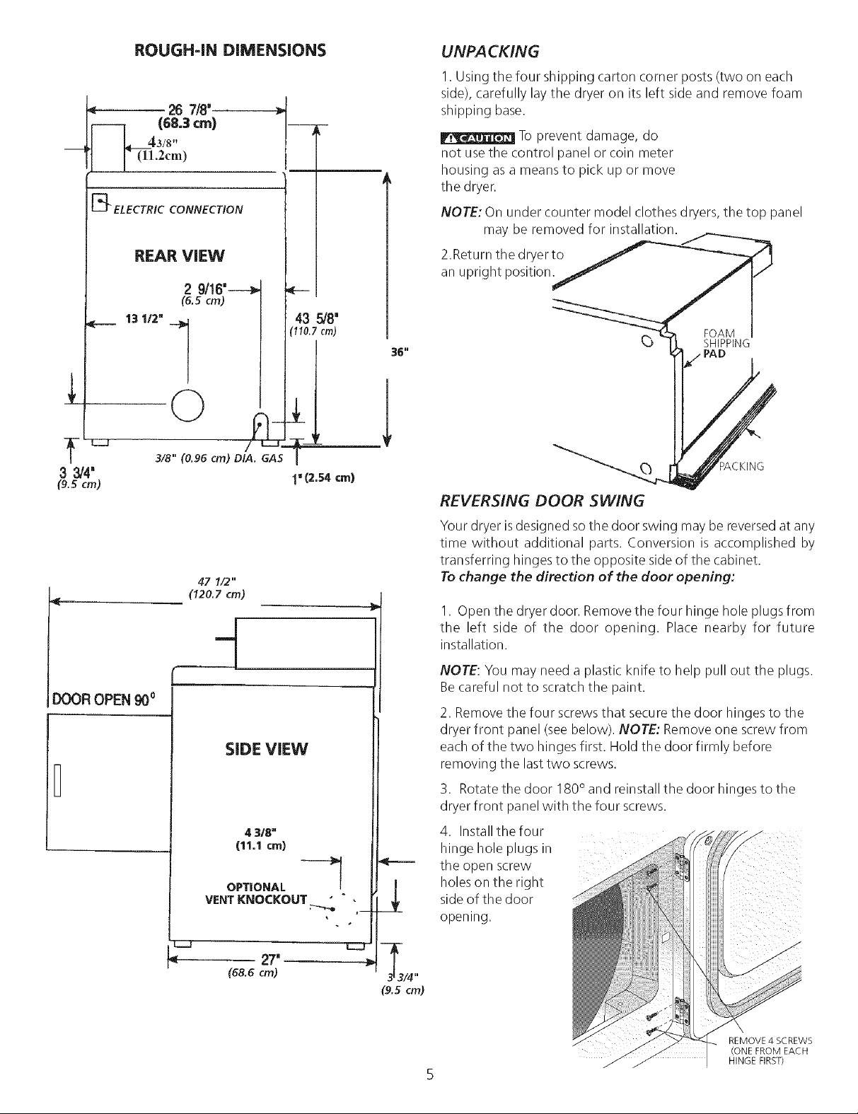
ROUGH=INDiMENSiONS
< 267/8'-------)
_d4 (68.3 cm)
3/8"
.2cm)
[_ ELECTRIC CONNECTION
UNPACKING
1. Using the four shipping carton corner posts (two on each
side), carefully lay the dryer on its left side and remove foam
shipping base.
To prevent damage, do
m
not use the control panel or coin meter
housing as a means to pick up or move
the dryer.
NOTE: On under counter model clothes dryers, the top panel
may be removed for installation.
3314"
(9. 5 cm)
<
REAR ViEW
2 9/16'---_
(6.Scm)
13 112"
3/8" (0.96 cm) DIA. GAS
47 1/2"
(120.7 cm)
43 5/8'
(110.7 cm)
1"(2.54crn)
36"
2.Return the dryer to
an upright position.
FOAM
SHIPPING
_, PAD
REVERSING DOOR SWING
Your dryer is designed so the door swing may be reversedat any
time without additional parts. Conversion is accomplished by
transferring hinges to the opposite side of the cabinet.
To change the direction of the door opening:
I. Open the dryer door. Remove the four hinge hole plugs from
the left side of the door opening. Place nearby for future
installation.
DOOR OPEN 90°
SiDE ViEW
4 3/8"
(11.1cm)
OPTIONAL --_
VENTKNOCKOUT;---,_,
< 27'
(68.6cm)
NOTE: You may need a plastic knife to help pull out the plugs.
Be careful not to scratch the paint.
2. Removethe four screws that secure the door hinges to the
dryer front panel (see below). NOTE: Remove one screw from
each of the two hinges first. Hold the door firmly before
removing the lasttwo screws.
3. Rotate the door 180° and reinstall the door hinges to the
dryer front panel with the four screws.
4. Install the four
hinge hole plugs in ..........
the open screw
holes on the right
side of the door
opening.
REMOVE 4 SCREWS
(ONE FROM EACH
HINGE FIRST)
5
Page 6

ELECTRICAL INSTALLATION
Before proceeding with electrical installation, install the dryer's
coin-metering system (when used) in accordance with the
separate instructions provided with the meter.
GREEN
SCREW SILVER
NEUTRAL
GROUND
WIRE
/TERMINAL
i
The following are specific requirements for proper
and safe electrical installation of your dryer Failure to follow
these instructions can create electrical shock and/or a fire hazard.
This appliance MUST be properly qrounded. Electrical
shock can result if the dryer is not properly grounded. Follow the
instructions in this manual for proper grounding.
extension cords are not designed to withstand the amounts of
electrical current this dryer utilizes and can melt, creating electrical
shock and/or fire hazard. Locatethe dryerwithin reach of the receptacle
for the length power cord to be purchased, allowing some slack in the
cord. Refer to the pre-installation requirements in this manual for the
proper power cord to be purchased.
A U.L listed strain relief must be installed onto power
cord. If the strain relief is not attached, the cord can be pulled out of
the dryer and can be cut by any movement of the cord, resulting in
electrical shock.
Do not usean aluminum wired receptacle with acopper
wired power cord and plug (or vice versa). A chemical reaction occurs
between copper and aluminum and can cause electrical shorts. The
proper wiring and receptacle is a copper wired power cord with
a copper wired receptacle.
NOTE: Dryers operating on 208 volt power supply will have longer
drying times than operating on 240 volt power supply.
i ELECTRIC Dryer }
F_I_I Improper connection of the equipment grounding
conductor can result in a risk of electrical shock. Check with a licensed
electrician if you are in doubt as to whether the appliance is properly
grounded.
For a grounded, cord-connected dryer:
1. The dryer MUST be grounded. In the event of a malfunction or
breakdown, grounding will reduce the risk of electrical shock by a
path of least resistance for electrical current.
2. If your dryer is equipped with a power supply cord having an
equipment-grounding conductor and a grounding plug, the plug
MUST be plugged into an appropriate, copper wired receptacle
that is properly installed and grounded in accordance with all
local codes and ordinances. If in doubt, call a licensed electrician.
Do not modify plug provided with the appliance.
For a permanently connected dryer:
1. The dryer MUST be connected to a grounded metal, permanent
wiring system; or an equipment grounding conductor must be
run with the circuit conductors and connected to the equipment-
grounding terminal or lead on the appliance.
ALL ELECTR/C Dryers
Do not use an extension cord with this dryer. Some
GROUNDING REQUIREMENTS
i
, HTENNUT
TO THESE
!ADS
REL EF
MOUNTING I
BRACKET POWER CORD
ELECTRICAL CONNECTIONS
FOR 3-WIRE SYSTEM
J
1.
Remove the screws securing the terminal block access cover and
the strain relief mounting bracket located on the back of the dryer
upper corner.
2. Install a U.L listed strain relief into the power cord entry hole of
the mounting bracket. Finger tighten the nut only at this time.
3. Thread a U.L listed 30 amp. power cord, NEMA 10-30 TypeSRDT,
through the strain relief.
4. Attach the power cord neutral (center wire) conductor to the silver
colored center terminal on the terminal block. Tighten the screw
securely.
5. Attach the remaining two power cord outer conductors to the
outer brass colored terminals on the terminal block. Tighten both
screws securely.
Pq'ql_2_l_:_l Do not make a sharp bend or crimp wiring/conductor
6. Reattach the strain relief mounting bracket to the back of the
dryer with two screws. Tighten screws securely.
7. Tighten the screws securing the cord restraint firmly against the
power cord.
8. Tighten the strain relief nut securely so that the strain relief does
not turn.
9. Reinstall the terminal block cover.
GREEN GROUND WIRE
GROUND _ SILVERTERMINAL
GROUND_-_ _
at connections.
ELECTR/C Dryer
GREENPOWER CORD
oi/_WHIT E TO THESEWIRE _ _,__yBLACK TIGHTEN NUT
i ALLGASDryers i
This dryer is equipped with a three-prong (grounding) plug for your
protection against shock hazard and should be plugged directly into
a properly grounded three-prong receptacle. Do not cut or remove
the grounding prong from this plug.
_ _- // NUT THREADS
/// RELIEF\_"Q,) // "_
/7/MOUN NG \ I/'//
, , c OW R
ELECTRICAL CONNECTIONS
FOR 4-WIRE SYSTEM
Page 7

ELECTRICAL CONNECTIONS
FOR 4-WIRE SYSTEM (Con't)
I ELECTR/CDryer 1
1, Remove the screws securing the terminal block access cover and
the strain relief mounting bracket located on the back of the dryer
upper corner.
2. Install a U.L listed strain relief in the entry hole of the mounting
bracket. Finger tighten the nut only at this time.
3. Remove the ground wire from the green ground screw located
above the terminal block.
4. Thread a U.L listed 30 amp power cord, NEMA 14-30 type ST or
SRDT through the strain relief.
(_ TYPICAL 4
CONDUCTOR BLACK 240V
RECEPTACLE
WHITE NEUTRAL
TYPICAL4 _,RED 240v
CONDUCTOR CORD "_,-
30 AMP NEMA 14-30 TYPE SRDT OR ST
5. Attach the green power cord ground wire to the cabinet with
the green ground screw.
6. Attach the white (neutral) power cord conductor from the power
cord and the neutral ground wire from the dryer harness
(removed from the ground screw in step 3) to the silver-colored
center terminal on the terminal block. Tighten the screw securely.
7. Attach the red and black power cord conductors to the outer
brass colored terminals on the terminal block.
Do not make a sharp bend or crimp wiring/conductor
at the connections.
8. Tighten the screws securing the cord restraint firmly against the
power cord.
9. Tighten the strain relief nut securely so the strain relief does not
turn.
10. Reinstall the terminal block access cover.
"_GREEN GROUND
INSTALLATION
1. GAS CONNECTION (Gas dryers only)
a. Remove the shipping cap from gas pipe at the rear of the
dryer.
NOTE: DO NOT connect the dryer to LP. gas service without
converting the gas valve. An L.R conversion kit must be
installed by a qualified gas technician.
2. Connect the exhaust duct to outside exhaust system. Use duct
tape to seal all joints.
3. With the dryer in its final position, adjust one or more of the legs
until the dryer is resting solid on all four legs. Place a level on top
of the dryer. THE DRYER MUST BE LEVEL AND RESTING SOLID
ON ALL FOUR LEGS.
4. Plug the power cord into a grounded outlet. NOTE: Check to
ensure the power isoff at circuit breaker/fuse box before plugging
the power cord into the outlet.
5. Turn on the power at the circuit breaker/fuse box.
Before operating the dryer, make sure the dryer area is
c/ear and free from combustible materials, gasoline, and other
flammable vapors. Also see that nothing (such as boxes, clothing,
etc.) obstructs the flow of combustion and ventilation air.
6. Run the dryer through a cycle check for proper operation.
NOTE: On gas dryers, before the burner will light, it is necessary
for the gas line to be bled of air. If the burner does not light
within 45 seconds the first time the dryer is turned on, the safety
switch will shut the burner off. If this happens, turn the timer to
"OFF" and wait 5 minutes before making another attempt to
light.
7. Place these instructions in a location near the dryer for future
reference.
NOTE: A wiring diagram is located inside the dryer.
REPLACEMENT PARTS
If replacements parts are needed for your dryer, contact the source
where you purchased your dryer, call 1-800-944-9044, or visit our
website, www.frigidaire.com, for the Frigidaire Company
Authorized Parts Distributor nearest you.
Label all wires prior to disconnection when servicing
controls. Wiring errors can cause improper and dangerous operation.
Verify proper operation after servicing.
Destroy the carton and plastic bags after the dryer is
unpacked. Children might use them for play. Cartons covered with
rugs, bedspreads, or plastic sheets can become airtight chambers
causing suffocation. Place all materials in a garbage container or
make materials inaccessible to children.
The instructions in this manual and all other literature
included with this dryer are not meant to cover every possible
condition and situation that may occur. Good safe practice and
caution MUSTbe applied when installing, operating and maintaining
any appliance.
Lint Blade Retaining Pin Location and Orientation
b. Connect a 1/2 inch (1.27 cm) I.D. semi-rigid or approved pipe
from gas supply line to the 3/8 inch (0.96 cm) pipe located on
the back of the dryen Use a 1/2 inch to 3/8 inch (1.27 cm to
0.96 cm) reducer for a connection. Apply an approved thread
sealer that is resistant to the corrosive action of liquefied
gases on all pipe connections.
c. Open the shutoff valve in the gas supply line.
d. Test all connections by brushing on a soapy water solution.
NEVER TEST FOR GAS LEAKS WITH AN OPEN FLAME.
Install the pins after the lint blade is installed.
7
Page 8

Your appliance is covered by a one year Iknited warranty. For one year from your original date of purchase, Electrolux will
pay all costs, except as set forth below, for repairing or replacing any parts of this appliance that prove to be defective in
materials or workmanship when such appliance is installed, used, and maintained in accordance with the provided instructions.
Exclusions
This warranty does not cover the following=
1. All labor costs on commercial laundry products.
2. Payment acceptance devices for commercial laundry products.
3. Products with odginal serial numbers that have been removed, altered or cannot be readily determined.
4. Normal wear and tear and gradual deterioration.
5. Product that has been transferred from its odginai owner to another party or removed outside the USA or Canada.
6. Rust on the interior or exterior of the unit.
7. Products purchased "as-is".
8. Food loss due to any refrigerator or freezer failures.
9. Damage caused at any time during shipment.
10. Service calls which do not involve malfunction or defects in materials or workmanship, or for appliances used other than in
accordance with the provided instructions.
11. Service calls to correct the installation of your appliance or to instruct you how to use your appliance.
12. Expenses for making the appliance accessible for servicing, such as removal of trim, cupboards, shelves, etc., which are not a part of
the appliance when it is shipped from the factory.
13. Service calls to replace appliance light bulbs, air filters, water filters, other consumables, or knobs, handles, or other cosmetic parts.
14. Surcharges including, but not limited to, any after hour, weekend, or holiday service calls, toils, ferry trip charges, or mileage
expense for service calls to remote areas, including the state of Alaska.
15. Damages to the finish of appliance and/or location that are incurred during installation, including but not limited to floors, cabinets,
walls, etc.
16. Damages caused by: services performed by unauthorized service companies; use of parts other than genuine Electrolux parts or parts
obtained from persons other than authorized service companies; or external causes such as abuse, misuse, inadequate power supply,
accidents, fires, or acts of God.
17. Labor costs after ninety (90) days from your original date of purchase incurred for product repair or replacement as provided herein
for appliances operated by a concessionaire or vendor in a trailer or other motorized vehicle or at varying locations.
DISCLAIMER OF IMPLIED WARRANTIES; LIMITATION OF REMEDIES
CUSTOMER'S SOLE AND EXCLUSIVE REMEDY UNDER THIS LIMITED WARRANTY SHALL BE PRODUCT REPAIR OR REPLACEMENT
AS PROVIDED HEREIN. CLAIMS BASED ON IMPLIED WARRANTIES, INCLUDING WARRANTIES OF MERCHANTABILITY OR FITNESS
FOR A PARTICULAR PURPOSE, ARE LIMITED TO ONE YEAR OR THE SHORTEST PERIOD ALLOWED BY LAW, BUT NOT LESS THAN
ONE YEAR. ELECTROLUX SHALL NOT BE LIABLE FOR CONSEQUENTIAL OR INCIDENTAL DAMAGES SUCH AS PROPERTY DAMAGE
AND INCIDENTAL EXPENSES RESULTING FROM ANY BREACH OF THIS WRITTEN LIMITED WARRANTY OR ANY IMPLIED WARRANTY.
SOME STATES AND PROVINCES DO NOT ALLOW THE EXCLUSION OR LIMITATION OF INCIDENTAL OR CONSEQUENTIAL DAMAGES,
OR LIMITATIONS ON THE DURATION OF IMPLIED WARRANTIES, SO THESE LIMITATIONS OR EXCLUSIONS MAY NOT APPLY TO YOU.
THIS WRITTEN WARRANTY GIVES YOU SPECIFIC LEGAL RIGHTS. YOU MAY ALSO HAVE OTHER RIGHTS THAT VARY FROM STATE
TO STATE.
If You Need Keep your receipt, delivery slip, or some other appropriate payment record to establish the warranty period should
Service service be required. If service is performed, it is in your best interest to obtain and keep all receipts. Service under
this warranty must be obtained by contacting Electrolux at the addresses or phone numbers below.
This warranty only applies in the USA and Canada. In the USA, your appliance is warranted by Electrolux Major Appliances North
America, a division of Electrolux Home Products, Inc. In Canada, your appliance is warranted by Electrolux Canada Corp. Electrolux
authorizes no person to change or add to any obligations under this warranty. Obligations for service and parts under this warranty must
be performed by Electrolux or an authorized service company. Product features or specifications as described or illustrated are subject
to change without notice.
USA
1.886.738.1640
Electrolux Major Appliances
North America
RO. Box 212378
Augusta, GA 30907
Electrolux
Electrolux Canada Corp.
5855 Terry Fox Way
Mississauga, Ontario, Canada
Canada
1.866.738.1640
L5V 3E4
Page 9

REOUERIMIENTOS DE INSTALA CION
PRELIMINARES
Herramientas y materiales necesarios para la instalaci6n:
1. Destornillador Phillips
2. Alicates universales
3. Nivel de carpintero
4. Destornillador para tornillo de cabeza plana o recta
5. Cinta para ductos
6. Ducto metalico rigido o flexible de 4"(10,2 cm)
7. Caperuza de salida
8. Sellador de tuberias (gas)
9. Un cuchillo de pl_istico
REQUERIMIENTOS ELECTRICOS
[ Secadoras ELLeCTR/CA, ]
ClRCUITO - Circuito derivado individual de 30 amperes, con
fusibles de 30 amp. del tipo de retardo minimo o disyuntores.
ALIMENTACIONELECTRICA - Corriente alterna, monoffisica, 60
Hz, 240 voltios; trifilar.
CORDON ELECTRICO - En la secadora se DEBE usar un cord6n
electrico trifilar NEMA 10-30 tipo SRDT para un voltaje nominal
minimo de 240 voltios CA, 30 amp, con 3 conectores de horquillas
con terminales abiertos y extremos dirigidos hacia arriba o
conectores de anillo cerrado y marcados para uso en secadoras
de ropa. Si siendo instalado en una nueva instalacibn del circuito
del rama, un vehiculo casero, recreacional (mbvil) manufacturado
o un _irea que prohiben el poner a tierra a traves del conductor
neutral, se DEBE utilizar un cordbn electrico tetrafilar NEMA 14-
30 tipo SRDT o ST (como sea necesario) para un voltaje nominal
minimo de 240 voltios CA, 30 amp con 4 conectores de horquillas
con terminales abiertos y extremos dirigidos hacia arriba o
conectores de anillo cerrado y marcados para uso en secadoras
de ropa. Ver CONEXIONES ELECTRICAS PARA SISTEMAS
TETRAFILARES.
TOMACORRIENTE - El tomacorriente NEMA 10-30R debe estar
ubicado de manera que elcord6n electrico Ilegue hasta el cuando
la secadora este instalada.
ALIMENTACIONELI_CTRICA
CAJA PRINCIPAL DE FUSIBLES CON CONDUCTOR NE UTRO
4 PUESTO A TIERRA, TRIRLAR, 120-240 VOLTIOS 60
CICLOS
FUSIBLES DE ACCION RETARDADA
DE 30 AMP O DISYDNTOR
-_ CONDUCTOR NEUTRO
TOMACORRIENTE _ _ _ _
(COBRE)
iNSTALACiON SUJETA A LOS
REGLAMENTOS LOCALES
NEMA I0-30R (COBRE)
NOTA:No saque por
espiga de puesta a
tierra del enchufe.
ning_n motivo la _k_
\ U ESP=eADEPUESTA
A TIERRA
REQUERIMIENTOS DEL SISTEMA DE ESCAPE
Utilice solamente ductos met_ilicos rigidoso flexibles de 4"
(10,2 cm) de di_imetro (minimo) y una caperuza de salida de uso
aprobado, con registros que giren hacia afuera que seabren cuando la
secadora se encuentra en funcionamiento. Cuando la secadora se
detiene, los registros se cierran autom_iticamente para evitar las
corrientes de airey laentrada de insectosy roedores. Paraevitar obstruir
la salida, mantenga una altura libre minima de 12"(30,5 cm) entre la
caperuza de salida y el piso o entre cualquier otra obstruccion.
Los siguientes requerimientos son
especificos para el funcionamiento correcto y seguro de su
secadora. El incumplimiento de estas instrucciones puede causar
prolongaci6n ex cesiva del tiempo de secado y riesgos de incendio.
_No useductos flexibles de pl_istico para el escape de la secadora.
Sepuede acumular un exceso de pelusasen el sistema de escape,treat
un riesgo y obstruir el flujo de aire. La restricci6n del flujo del aire
prolongar_i eltiempo de secado. Sisu sistema de escape actual tiene
ductos de plfistico o de laminas met_ilicasdelgadas, reempl_icelo con
un ducto metfilico rigido o flexible. Asegurese de que los ductos
existentes no tengan pelusas antes de instalar el ducto de la
secadora.
_Si el escape de la secadora no se diriqe al exterior, algunas pelusas
finas ser_qnsopladas hacia el recinto donde se efectua el lavado. La
acumulacion de pelusas en cualquier lugar de la construccion, puede
crear un peligro para la salud y un riesgo de incendio, iEIsistema de
escape de la secadora DEBEestar dirigido hacia el exterior de la
construcci6n!
_No permita que los materiales combustibles (por ejemplo: la ropa,
cortinas/cortinajes, papel) tengan contacto con los ductos. Elescape
de la secadora NO DEBE dirigirse hacia el interior de una chimenea,
hacia una pared, hacia el cielo raso o hacia cualquier otro espacio
reducido del edificio, donde puede ocurrir acumulaciOn de pelusas y
constituir un peligro de incendio.
_ Exceder la Iongitud del conducto rigido o los numeros de codos
permitidos en los diagramas "LARGO M,4XIMO" puede disminuir la
capacidad de exhaustacion del sistema. Obstruir el conducto puede
provocar peligro de incendio, asicomo aumentar el tiempo de secado.
_No coloque un filtro en elextremo del escapedel sistema niemplee
tornillos o remaches para ensamblar el sistema de escape. Laspelusas
podrian quedar atrapadas en los filtros, en los tornillos o en los
remaches, Io cual obstruiria el sistema de escape y crearia un riesgo de
incendio, asicomo tambien prolongaria eltiempo de secado. Useuna
caperuza de salida adecuada para el extremo del ducto que salga al
exterior de la vivienda y selle todas lasjuntas con cinta adhesiva para
ductos. Todos losaccesorios detuberia machos, DEBEN ser instalados
aguas abajo del flujo de aire.
[ ]
CIRCUITO - Circuito individual derivado de 15 amp, con fusibles
de 15 amp. de retardo m_iximo o disyuntor.
ALIMENTAClON ELECTRICA - Corriente alterna, monof_isica,
60 Hz, 120 voltios, trifilar.
CORDONELECTRICO- Lasecadoraest.1equipadacon un cord6n
electrico trifilar para 120 voltios.
Riesgo de explosi6n. Noinstale lasecadora
donde se guarda gasolina u otros materiales inflamables. Silasecadora
seinstala en un garage, ella debe estar por Io menos 18 pulgadas (45,7
cm) por encima del suelo. El incumplimiento puede resultar en la
muerte, explosion, incendio, o quemaduras.
9
Page 10

NQmero
de Codos
a 90 °
o
I
2
3
4
Numero
de Codos
a 90 °
LARGO MAXIMO
del Conducto Met&lico Rigido
de 4" (10,2 cm) de Diametro
TIPO DE CAPERUZA DE SALIDA
(Preferido)
Apersianada
-,-I4"t
(lo,2 cm)
60 pies (18,28 m)
52 pies (15,84 m)
44 pies (13,41 m)
32 pies (9,75 m)
28 pies (8,53m)
LARGO MAXIMO
del Conducto Metalico Flexible
de 4" (10,2 cm) de Diametro
TIPO DE CAPERUZA DE SALIDA
(Preferido)
Apersianada
(6.35 cm)
48 pies(14,63 m)
40 pies(12,19 m)
32 pies (9,75 m)
24 pies (7,31 m)
16 pies (4,87 m)
Elaislante que debe atravesa r el sistema puede causar condensaciOn
y disminuir asi la capacidad de exhaustaci6n del sistema.
o La capacidad de exhaustacion de un sistema de exhaustaci6n
comprimido o ondulado puede disminuirse.
Elsistema de exhaustacion debe de ser inspeccionado y limpiado por Io
menos cada 6 meses de uso normal. Cuanto mas la secadora esta uti-
lizada, mas debe verificar el buen funcionamiento del sistema de
exhaustacion y de la tapa del orificio de ventilacion.
UBICA CION DEL ESCAPE
Todas las secadoras vienen de fabrica equipadas con escape trasero.
Sin embargo, en las secadoras electricas, el escape puede hacerse al
lado derecho o izquierdo del gabinete o en la parte inferior de la secadora.
Enlas secadoras a gas, el escape del aire puede estar en el lado derecho
del gabinete o en la parte inferior de la secadora. El escape direccional
puede efectuarse instalando un Juego de Escape, P/N 131456800,
disponible atraves de su distribuidor de repuestos. Siga las instrucciones
que se suministran con el juego.
DIMENSIONES PARA LA UBICACION DEL DUCTO DE ESCAPE
(10,2 cm}
o
I
2
3
INSTALE LOS ACCESORIOS MACHOS EN LA DIRECCION CORRECTA
Para las instalaci6nes cuyas sistema de exhaustaci6n no se
encuentre en el diagrama, se puede utilizar el metodo a conti-
nuaciOn para determinar si el sistema de exhaustaciOn es apro-
piado.
1. Conecte un manOmetro a tubo inclinado o digital entre la
secadora y el union de exhaustaciOn de la secadora.
2. Ponga el contador de tiempo de la secadora y la temperatura
a aire frio (enfiriamiento), y la secadora en la posiciOn de
marcha.
3. Lea la medida indicada en el manOmetro.
4. La baja presiOn NO DEBE exceder 0.75 pulgada de la columna
de agua. Si la baja presiOn es inferior a 0.75" de la columna
deagua, elsistema esaceptable. Si la lectura indica una
presiOn superior a 0.75" de la columna de agua, la capacidad
del circuito es insuficiente y la instalaciOn es inaceptable.
Aungue un sistema vertical sea aceptable, algunas circunstancias
atenuantes pueden afectar el funcionamiento de la secadora:
• 5e debe utilizar solamente conductos metalicos rigidos.
e Una salida del sistema vertical en el techo, puede exponerle a un
corriente de aire descendente y disminuir asi su capacidad de
exhaustaci6n.
30 pies (9,14m)
22 pies (6,71 m)
14 pies (4,27 m)
NO RECOMENDADO
_'6.35cm_
18 pies (5,49 m)
14 pies (4,27 m)
10 pies (3,05 m)
REQUERIMIENTOS DEL SUMINISTRO DE GAS
Reemplace la tuberia de conexibn de cobre
que no est& recubrida con pl&stico. El laton inoxidable o recubrido
con plastico DEBE SERutilizado.
1. La instalacion DEBE hacerse cumplir con los codigos locales o en
ausencia de los mismos, de acuerdo con los estandares del National
Fuel Gas Code (Codigo Nacional para Gases Combustibles), ANSI
Z223.1 (la ultima edition).
2. Latuberia dealimentaciOn de gasdebeser de 1/2 pulgada (1,27 cm)
de diametro.
3. Si est_fi permitido por los cOdigos locales, se puede usar tubefia
de metal para conectar su secadora a la linea de suministro
de gas. La tuberia DEBE set fabricada de acero inoxidable o
cobre recubierto de pl_stico.
4. La tuberia de alimentaci6n de gas DEBEtener una Ilave de cierre
individual.
5. Una toma de 1/8 de pulgada (0,32 cm) N.RT. accesible para conexion
del manOmetro de prueba, DEBE ser instalada inmediatamente
aguas arriba de la conexion de la tuberia de alimentaciOn de gas a la
secadora.
6. La secadora DEBE ser desconectada del sistema de tuberias de
alimentaciOn de gas durante cualquier ensayo de presiOn del sistema
de tuberias de alimentaciOn de gas realizado a presiones de prueba
de mas de 1/2 Ibs/pulg. 2 (3,45 kPa).
7. La secadora DEBEaislarse del sistema de tuberias de alimentaci6n
de gas durante cualquier ensayo de presi6n del sistema de tuberias
de alimentacion de gas realizado en ensayos de presiOn iguales o
inferiores a 1/2 Ibs/pulg. 2 (3,45 kPa).
10
Page 11

UBICA CION DE SU SECADORA
NO INSTALE SU SECADORA:
1. Enun lugar donde puede haber goteos de agua o quede expuesta
a las inclemencias del tiempo.
2. En un _ireadonde pueda entrar en contacto con cortinas, cortinajes
o cualquier otra cosa que obstruya el flujo de combusti6n y
ventilaci6n de aire.
3. Sobre alfombras. Elpiso DEBEserfirme con un desnivel maximo de
1pulgada (2,54 cm).
/NSTALACION DENTRO DE UN NICHO 0 ARMARIO
1. Sila secadora es instalada en un dormitorio, cuarto de bano, nicbo
o armario, el tubo del escape DEBE set instalado hacia el exterior.
2. No sedebe instalar ningOn otto artefacto que queme combustible
en el mismo armario en que est,1instalada la secadora a Gas.
3. La secadora necesita espacio a su alrededor para una ventilaci6n
adecuada.
Se requiere como minimo una abertura de 120 pulgadas cuadra-
das (774,2 cm2), dividida equitativamente para la parte superior e
inferior de la puerta. Cuando se instala una puerta, es necesario
proveer aberturas para el aire. Una puerta apersianada con abertu-
ras para el aire en todo el largo de la puerta es aceptable.
DESPEJES MiNIMOS DE INSTALACION (Pulgadas)
PARTE PARTE PARTE
DELANTERA LADOS TRASERA SUPERIOR
Alcoba 0 (0 cm) 0 (0 cm) 0 (0 cm) 15 (38,1 cm)
Armario 1 (2,54 cm) 0 (0 cm) 0 (0 cm) 15 (38,1 cm)
Ventilaci6n requirida en la puerta del armario: dos aberturas rejilladas
cada 60 pulg. 2 (387 cm2) -- 3" (7,6 cm) desde la parte inferior y
superior de la puetra.
EL TUBO DEL ESCAPEDE LA SECADORA DEBE SER INSTALADO
HACIA ELEXTERIOR.
NO INSTALE LA SECADORA EN UN ARMARIO CON PUERTA
MA CIZA,
60 Pulgo2
{387,1 ¢m2)
PUERTA DEL ARMARmO
5. Lassiguientes ilustraciones muestran las dimensiones mfnimas de
espacio libre que debe existir para el buen funcionamiento de la
secadora cuando se instala en un nicho o en un armario.
NO
L
Correcto
sl
©
Incorrecto
L
11
Correcto
Incorrecto
Incorrecto
Page 12

MODELOS AUTONOMOS CON CONSOLA
SUPERIOR
DIMENSIONES PARA LA INSTALACI6N
_68.3cm_
m
L43/8"
[_ CONEXI6N EL_:CTRICA
26 7/8" 1
" (11.2cm)
DESEMBALAJE
1. Utilizando lascuatro esquineras de embarque de la caja de carton
(dos a cada lado), coloque cuidadosamente la secadora sobre el
costado izquierdo y saque la base de espuma de embarque.
_Para evitar danos, no use el panel de control como
un medio para levantar o mover la secadora.
NOTA: En los modelos de secadoras encastradas, el panel superior
puede set removido para la instalacion.
2. Vuelva la secadora a su posici6n vertical.
13 1/2" -_
(34,4 cm) [
3 3/4" (9,5 cm)
PUERTA
ABIERTAA90 °
B
2 9/16" (6,5 cm)
0
CONEXION DE LA
TUBERiA DE GAS
DE 3/8" (0,96cm)
VISTA POSTERIOR
47112"
(120,7 cm)_ 17(432)
44
(111.8ore)
36"
__ (91,5 cm)
1
1" (2,54 cm)
--1
PLACA DE
ESPUMA DE
_¢/ EMBARQUE
MPAQUE
PUERTA REVERSIBLE
Su secadora ha sido diser_ada para que la puerta pueda ser cambiada
de lado en cualquier momento sin necesidad de piezas adicionales.
La conversion se hace transfiriendo las bisagras al lado opuesto del
gabinete.
Como cambiar ladireccion de apertura de la puerta:
1. Abra lapuerta de la secadora. Quite loscuatro receptores del agujero
de la bisagra del lado izquierdo de la apertura de la puerta.
Coloquelos en un lugar cercano para futura instalaci6n. NOTA:
Puede que se necesite un cuchillo de pl_istico para poder sacar los
receptores. Tenga cuidado de no rayar la pintura.
2. Quite los cuatro tornillos que aseguranlas bisagras de la puerta al
panelfrontal de lasecadora (ver figura abajo). NOTA: Primero quite
untornillo decada una de lasbisagras. Mantenga la puerta sujetada
firmemente antes de quitar los dos 01timostornillos.
3. Gire la puerta 180° y vuelva a colocar las bisagras de la puerta en el
panel frontal con los cuatro tornillos.
4. Instale los cuatro receptores de los agujeros de las bisagras en los
agujeros abiertos en el lado derecho de la apertura de la puerta.
43/8"(11,1 cm) -----_
DISCO OPCl6NAL /
REMOVlBLE PARA-_....._
VENTILACl6N
27'
(68,6 cm)
VISTA LATERAL
.
i --
QUITE LOS CUATRO
TORNILLOS (PRIMERO QUITE
UNO DE CADA BISAGRA)
Page 13

INSTALA CION ELI_CTRICA
i TODAS/assecadorasELtCTRICAS i
Los siguientes requerimientos son
especificos para el funcionamiento correcto y seguro de su
secadora. El incumplimien to de estas instrucciones puede causar
p_r_a del tiempo de secado y riesgos de incendio.
_*_J__ Este artefacto DEBE ser puesto a tierra de
manera correcta. Sila secadora no est_qdebidamente puesta a tierra se
puede producir un choque electrico. Siga las instrucciones indicadas
en_puesta a tierra en forma correcta.
_lr! , By - _ • No use un cordon de extension con esta
secadora. Algunos cordones de extension no pueden soportar la
cantidad de corriente electrica que utiliza esta secadora y pueden
fundirse, creando un peligro de choque electricoy/o incendio. Ubique
la secadora de manera que el cordon electrico Ilegue hasta el
tomacorriente que se va a usar, dejando un poco de holgura para el
cordon. ConsultelosrequerimientosdeinstalaciOn preliminares
indicados en este manual para el cordon electrico que debe set
TORNILLO
VERDE DE
PUESTA A ,
TERRA
CABLE DE
PUESTA
ATIERRA
NEUTRAL
BORNE PLATEADO
ATORNILLE LA
TUERCA EN ESTAS
ROSCAS
Se debe instalar un anclaje aprobado por el U. L.
para el cordon electrico. Si no se utiliza un anclaje para sujetar el cordon
electrico, este puede salirse de la secadora y cortarse con cualquier
movimiento, resultando en un choque electrico.
No utilice un tomacorriente con cables de
aluminio con un cordon y un enchufe de cobre (o viceversa). Se produce
una reacciOn quimica entre el cobre y el aluminio que puede causar
cortaci rcu itos. El cableado y tomacorriente apropiado es un cord6n
electrico equipado con conductores de cobre con un tomacorriente
con conductores de cobre.
NOTA: Las secadoras que operan con un suministro de energia de 208
voltios usar_in m_is tiempo de secado que aquellas que operan con un
suministro de energia de 240 voltios.
REQUERIMIENTOS PARA LA PUESTA A TERRA
SecadorasELECTRICAS i
LaconexiOn indebida del conductor de puesta atierra
del equipo puede ocasionar un riesgo de choque electrico. Consulte
con un electricista profesional si tiene alguna duda respecto a la puesta
atierra correcta del artefacto.
Para una secadora puesta a tierra con cordon elOctrico:
1. La secadora DEBEser puesta a tierra. En caso de malfuncionamiento
o falla, la puesta a tierra reducira el riesgo de choque electrico
proporcionando un trayecto de menor resistencia a la corriente
elOctrica.
2. Si su secadora est,1 equipada con un cordon electrico que posee un
conductor de puesta a tierra del equipo y un enchufe de puesta a
tierra, dicho enchufe DEBE set conectado a un tomacorriente
adecuado, debidamente instalado y puesto a tierra de acuerdo con
todos los cOdigos y reglamentos locales. Si tiene alguna duda
consulte a un electricista profesional. No modifique el enchufe
propercionado la aplicaci6n.
Para una secadora conectada permanentemente:
1. La secadora DEBEserconectada a un sistema de cableado met_qlico
permanente, puesto a tierra; o se debe instalar un conductor de
puesta a tierra de equipo junto con los conductores del circuito y
conectarse al borne de puesta a tierra del equipo o al cable del
artefacto.
[ TODAS/assecadorasaGAS I
Esta secadora est,1 equipada con un enchufe de tres espigas (de puesta 2.
a tierra) para proteccion en contra de choques electricos y debe ser
conectada directamenta en un receptaculo para tres espigas el cual debe
estar puesto a tierra. No corte ni elimine la espiga de puesta a tierra de 3.
este enchufe. 13
SOPORTE DE
MONTAIE DEL
ANCLAJE DE
CABLE CORDON ELECTRICO
CONEXIONES ELECTRICAS PARA
UN SISTEMA TRIFILAR
Secadoras EL ECTR/CA S ]
1. Saque los tornillos que sujetan la cubierta de acceso del tablero de
bornes y el soporte de montaje del anclaje del cordon, situado en la
esquina superior de la parte trasera de la secadora.
2. Instale un anclaje de cable aprobado por el U.L, en el orificio de
entrada del cordon electrico en el soporte de montaje. Luego apriete
la tuerca con los dedos solamente.
3. Inserte un cordon el_ctrico de 30 amp, NEMA 10-30 Tipo SRDT,
aprobado por el U.L, a traves del anclaje de cable.
4. Conecte el conductor neutro del cordon electrico (cable central) al
borne central plateado del tablero de bornes. Apriete firmemente el
tornillo.
5. Conecte los dos conductores externos restantes del cordon electrico
a los homes bronceados externos del tablero de bornes. Apriete
firmemente los tornillos.
No doble en forma pronunciada ni engarce los
cables/conductores en las conexiones.
6. Coloque nuevamente el soporte de montaje del anclaje de cable en
la parte trasera de la secadora con dos tornillos. Apriete firmemente
los tornillos.
7. Apriete firmemente los tornillos del anclaje de cable contra el cordon
electrico.
8. Apriete la tuerca del anclaje de cable a fin de que el anclaje no gire.
9. Coloque nuevamente la cubierta del tablero de bornes.
CONEXIONES ELL'CTRICAS PARA UN SISTEMA
TETRAFILAR
Secadoras ELf'CTR/CAS i
Saque los tornillos que sujetan la cubierta de acceso del tablero de
bornes y el soporte de montaje del anclaje de cable situado en la
esquina superior en la parte trasera de la secadora.
Instale un anclaje de cable aprobado por el U.L, en el orificio de
entrada del cordon electrico en el soporte de montaje. Luego apriete
la tuerca con los dedos solamente.
Desconecte el cable de puesta a tierra neutral del tornillo verde de
puesta a tierra situado en la parte superior del tablero de bornes.
Page 14

TORNILLO VERDE
DE PUESTA
ATIERRA
CABLE DE
PUESTA A
IIERRA
NELrI1RAL-_
ROJO"
4. Inserte un cord6n electrico tetrafilar de 30 amp, NEMA 10-30
TipoST o SRDT, aprobado por el U.L, a traves del anclaje de cable.
TOMACORRIENTE
TETRAFILARTIPICO 240 V
_,#NEGRO
/_' NEUTRO
_ BLANCO
CORDON
ELIeCTRICO %v
CORDON ELECTRICO DE 30 AMP NEIVIA 14_l_l:il!O SRDT 0 ST
5. Conecte el cable verde de puesta a tierra del cordon electrico al
gabinete mediante el tornillo verde de puesta a tierra.
6. Conecte el conductor blanco (neutro) del cord6n electricoy el cable
de puesta a tierra neutro del mazo de cables de la secadora al borne
plateado central del tablero de bornes.
7. Conecte los conductores rojo y negro del cord6n el_ctrico a los
bornes bronceados externos del tablero de bornes.
los cables/conductores en las conexi6nes.
8. Apriete firmemente los tornillos del anclaje de cable contra el cord6n
el_ctrico.
9. Apriete la tuerca del anclaje de cable a fin de que el anclaje no gire.
10. Coloque nuevamente la cubierta del tablero de bornes.
TETRAFILAR TIPICO PUESTA A TIERRA
No doble en forma pronunciada ni engarce
_ 240v ROJO
lira
/NSTALAC/ON
CONEXION DEL GAS (Secadoras a gas solamente)
a. Saque la tapa de embarque de la tuberia de gas de la secadora
situada en la parte trasera.
NOTA:
NO conecte la secadora al suministro de propano, sin primero
instalar eljuegodeconversi6n a propano. EIjuegode
conversi6n a propano debe set instalado pot un t_cnico de
gas calificado.
2. Conecte el ducto de escape al sistema de escape exterior. Utilice
cinta para obturar todas las uniones.
3. Con la secadora en su posici6n definitiva, regule uno o ross tornillos
niveladores, hasta que la secadora repose firmemente sobre los
cuatro tornillos. Coloque un nivel sobre la parte superior de la
secadora. LA SECADORA DEBE ESTAR A NIVEL Y REPOSAR
SOLIDA Y FIRMEMENTE SOBRE LOS CUATRO TORNILLO5
NIVELADORES.
4. Conecte el cordon electrico a un tomacorriente puesto a tierra.
NOTA: Aseg0rese de que la corriente este desconectada en el
disyuntodcaja de fusibles, antes de conectar el cordon electrico en
el tomacorriente.
5. Conecte la corriente en el disyuntor/caja de fusibles.
Antes de poner en funcionamiento la secadora,
asegOresede que no haya materia/es combustib/es, gaso/ina y otr os
vapores inf/amab/es cerca de/a secadora. Ademas asegOrese de
que no haya nada (tal como cajas, ropas, etc.) que obstruya el flujo
de/aire de combusti6n y venti/ad6n.
6. Haga funcionar la secadora durante un ciclo completo para
comprobar su buen funcionamiento.
NOTA: En las secadoras a gas, antes de encender el quemador es
necesario purgar el aire de la tuberia del gas. Si el quemador no
enciende dentro de 45 segundos, cuando la secadora seenciende
pot primera vez, el interruptor de seguridad apagar_i el quemador.
Si esto sucede, gire el contador de tiempo a la posici6n "OFF"
(apagado) yespere 5 minutos antes de intentar encender lasecadora
nuevamente.
7. Conserve estas instrucciones cerca de la secadora para referencia
futura.
NOTA: Dentro de'l sobre seencuentra un diagrama del cableado.
PIEZAS DE RECAMBIO
Si necesita obtener piezas de recambio para su secadora, pongase en
contacto con el distribuidor donde compr6 su secadora, Ilame 1-800-
944-9044, o visitan nuestros website www.frigidaire.com, para la
Distribuidor Autorizada Company de las Piezas de Frigidaire m_is
cercana usted.
Cuando se reparan los controles, marque todos los
cables con etiquetas antes de desconectarlos. Cualquier error de
cableado puede causar una operacion inadecuada y peligrosa.
Aseg0rese de que la secadora funcione adecuadamente despues de
'_._ Destruya la caja de carton, las bolsas de pkistico
y la banda met_ilica despues de haber desempacado el centro de
lavanderia. Los niflos pueden ponerse a jugar con ellos. Las cajas de
carton cubiertas con alfombras, colchas o pedazos de pl_istico pueden
convertirse en c_imaras sin aire y causar asfixia. Elimine todos los
os en la basura o fuera del alcance de los ninos.
Las instrucciones inclu idas en este manual y en
el resto de la documentacion que se entrega con la secadora no pueden
cubrir todas las situaciones o condiciones posibles que puedan
presentarse. Por Io tanto, se DEBEN seguir practicas seguras y tener
cuidado cuando se instala cualquier artefacto domestico.
b. Conecte una tuberia semirigida de 1/2" (1,27 cm) D.I. o una
tuberia aprobada, desdela linea desuministro de gasa la tuberia
de 3/8" (0,96 cm) ubicada en la parte trasera dela secadora. Utilice
un reductor de 1/2" (1,27 cm) a 3/8" (0,96 cm) para laconexion.
Aplique un sellador de roscas de uso aprobado, resistente a la
corrosi6n de los gases licuados, en todas las uniones de la
tuberia.
c. Abra lawqlvula de cierre en la tuberia de suministro de gas.
d. Pruebe todas las conexiones aplicando con una escobilla una
solucion jabonosa. NUNCA UTILICE UNA LLAMA ABERTA
PARA DETECTAR FUGA5 DE GAS.
La Rejilla para peiusas prender con aifileres Posicion et
Orientacion
Instalar les alfileres despues de la rejilla para para pelusas
instalaciOn.
14
Page 15

Su electrodom6stico esta cubierto por una garantia limitada de un aho. Durante un aho a partir de la fecha original de
compra, Electrolux cubrira todos los costos de reparacion o reemplazo de cualquier pieza de este electrodom6stico que se
encuentren defectuosas en materiales o mano de obra cuando el electrodom_stico se instala, utiliza y mantiene de acuerdo
con las instrucciones proporcionadas.
Esta garantia no cubre Io siguiente:
1, Todos los costos de mano de obra en productos para lavado comerciak
2, Dispositivos de aceptaci6n de pago para productos para lavado comerciaL
3. Productos a los que se les quitaron o alteraron los n0meros de serie originales o que no pueden determinarse con facilidad.
4, Desgaste normal y deterioro gradual por el uso,
5. Productos que hayan sido transferidos del dueno original a un tercero o que no se encuentren en los EE.UU. o en Canada1.
6. Oxido en el interior o exterior de la unidad,
7, Los productos comprados "previamente usados o productos de muestra" no est_in cubiertos por esta garantia.
8, P_rdida de alimentos por fallas del refrigerador o congelador.
9_ Dafio provocado en cualquier momento durante el env[o_
10. Las Ilamadas de servicio que no involucren el funcionamiento defectuoso ni los defectos de materiales o de mano de obra, o para
electrodomesticos que no sean utilizados para uso normal del hogar o de acuerdo con las instrucciones proporcionadas.
11. Llamadas de servicio para corregir errores de instalaci6n del electrodom_stico o para instruirlo sobre el uso del mismo.
12. Gastos para facilitar el acceso al electrodomestico para el servicio, tales como la remoci6n de molduras, armarios, estantes, etc. que
no eran parte del electrodomestico cuando se envi6 de la flibrica.
13. Llamadas de servicio para reparar o reemplazar bombillas, filtros de aire, filtros de agua, otros consumibles, perillas, manijas u otras
piezas decorativas.
14. Costos adicionales que incluyen, sin limitarse, cualquier Ilamada de servicio fuera de las horas de oficina, durante los fines de
semana o dias feriados, peajes, pasajes de transporte o millaje/kilometraje para Ilamadas de servicio en _ireas remotas, incluyendo
el estado de Alaska.
15. Danos al acabado del electrodomestico o al hogar que hayan ocurrido durante la instalaci6n, incluyendo, sin limitarse, los armarios,
paredes, etc.
16. Dan6s causados por: servicio realizado por companias de servicio no autorizadas, el uso de piezas que no sean piezas genuinas
Electrolux o piezas obtenidas de personas que no pertenezcan a companias de servicio autorizado, o causas externas como abuso,
mal uso, suministro el_ctrico inadecuado, accidentes, incendios, hechos fortuitos or desastres naturales.
17 Costos de mano de obra despu6s de noventa (90) d[as de su fecha original de compra en los que se incurra para la reparaci6n o
el reemplazo del producto tal como se dispone en el presente para electrodom6sticos operados por un concesionario o proveedor
en un cami6n o en otro veh[culo motorizado o en distintos lugares
RENUNCIA DE RESPONSABILIDAD DE GARANTIAS IMPLICITAS; LIMITACION DE ACCIONES LEGALES
LA 0NICA Y EXCLUSIVA OPCION DEL CLIENTE BAJO ESTA GARANTfA LIMITADA ES LA REPARACION O REEMPLAZO DEL PRODUCTO
SEGON SE INDICA. LOS RECLAMOS BASADOS EN GARANT[AS IMPL[CITAS, INCLUYENDO LAS GARANTIAS DE COMERCIALIZACION O
APTITUD DEL PRODUCTO PARA UN PROPOSITO ESPEC/FICO, ESTAN LIMITADOS A UN ANO O AL PERtODO M[NIMO PERMITIDO POR LEY,
PERO NUNCA MENOS DE
UN ANO. ELECTROLUX NO SERA RESPONSABLE POR DANOS CONSECUENTES O INCIDENTALES COMO POR EJEMPLO DANOS A LA
PROPIEDAD Y GASTOS INCIDENTALES OCASIONADOS POR EL INCUMPLIMIENTO DE ESTA GARANT[A ESCRITA O DE CUALQUIER GARANT[A
IMPL/CITA. ALGUNOS ESTADOS Y PROVINCIAS NO PERMITEN LA EXCLUSION O LIMITACION DE DANOS INCIDENTALES O CONSECUENTES
O LIMITACIONES EN LA DURACION DE LAS GARANTiAS IMPL[CITAS, DE MANERA QUE PUEDE QUE ESTAS LIMITACIONES O EXCLUSIONES
NO SE APLIQUEN EN SU CASO. ESTA GARANT[A ESCRITA LE OTORGA DERECHOS LEGALES ESPEC[FICOS. ESO POSIBLE QUE TAMBI_N
TENGA OTROS DERECHOS QUE VAR[AN DE UN ESTADO A OTRO.
Exdusiones Si tiene
que solicitar servicio
tecnico
Esta garantia s61ose aplica en los Estados Unidos y Canada En los EE.UU., su electrodomestico est,1 garantizado por Electrolux Major
Appliances North America, una divisi6n de Electrolux Home Products, Inc. EnCanada1,su electrodomestico est,1garantizado por Electrolux
Canada Corp. Electrolux no autoriza a ninguna persona a cambiar o agregar ninguna obligaci6n bajo esta garantia. Nuestras obligaciones
de reparaci6n y piezas bajo esta garantia deben ser realizadas por Electrolux o compania de servicio autorizado. Lasespecificaciones o
caracteristicas del producto segun se describen o ilustran est_in sujetas a cambio sin previo aviso.
Guarde su recibo, el comprobante de entrega o cualquier otro registro de pago adecuado para establecer el
periodo de la garantia si Ilegara a requerir servicio. Si se realiza la reparaci6n, le conviene obtener y
conservar todos los recibos. El servicio realizado bajo esta garantia debe set obtenido a trav_s de Electrolux
utilizando las direcciones o n0meros que se indican abajo.
EE. UI/.
1.866.738.1640
Electrolux Major Appliances
North America
RO. Box 212378
Augusta, GA 30907
8] Electrolux
Canada
1.866.738.1640
Electrolux Canada Corp.
5855 Terry Fox Way
Mississauga, Ontario, Canada
L5V 3E4
 Loading...