

Frigidaire FAS184N2A, FAS226N2A, FAS185N2A, FAS186N2A, FAS256N2A Product Information And Technical Manual
...Page 1
Product Information
g
and Technical Guide
2004 Room Air Conditioners
Safe Servicing Practices 3
ATTENTION SERVICERS!
To get a helping hand, visit the
Frigidaire Web Site at:
http://www.frigidaire.com
User name: service
Password: tips
Model Specifications 4-7
Compressor Overloads 8
Restrictor Tube Data 8
Receptacle Codes 9
Product Dimensions 10
Thermostat Dia
Fan/Blower Diagrams 13-14
Wiring Diagrams 15-17
Troubleshooting 18-20
rams 11-12
5995413183
July 2004
Page 2

TABLE OF CONTENTS
Safe Servicing Practices ............................................................................................3
Model Specifications ..................................................................................................4-7
Compressor Overload Data .......................................................................................8
Restrictor Tube Data ..................................................................................................8
Receptacle Outlet Codes ...........................................................................................9
Product Dimensions ..................................................................................................10
Control Thermostat Location Diagrams ................................................................... 11-12
Slider Casement ......................................................................................................11
Compact Electronic Control .....................................................................................11
Compact Rotary .......................................................................................................11
Intermediate Top Control Rotary .............................................................................. 11
2004 Heavy Duty Thermostat Locations ..................................................................12
2004 Builder Thermostat Locations .........................................................................12
2004 Slider Thermostat Locations ...........................................................................12
Fan and Blower Location Diagrams .........................................................................13-14
Compact .................................................................................................................13
18.5” - No Side Louvers ........................................................................................... 13
Slider Casement ......................................................................................................13
Motor .....................................................................................................................14
Heavy Duty Top Control ...........................................................................................14
Heavy Duty Side Discharge .....................................................................................14
Wiring Diagrams .........................................................................................................15-17
A232012 .................................................................................................................15
309201101/02 ......................................................................................................... 16
309201102/02 ......................................................................................................... 16
309902101/01 ......................................................................................................... 17
Troubleshooting ......................................................................................................... 18-20
2
Page 3
SAFE SERVICING PRACTICES - ALL APPLIANCES
To avoid personal injury or property damage, it is important that Safe Servicing
Practices be observed. The following are some limited examples of safe practices.
1. DO NOT attempt a product repair if you doubt your ability to complete it in a safe
and satisfactory manner.
2. Before servicing or moving an appliance
• Remove power cord from electrical outlet, trip circuit breaker to OFF position,
or remove fuse
• Turn off gas supply
• Turn off water supply
3. Never interfere with the proper operation of any safety device.
4. Use only OEM replacement parts cataloged for this appliance.
Substitutions may defeat compliance with safety standards set for home
appliances.
5. GROUNDING: The standard color coding for safety ground wires is GREEN, or
GREEN with YELLOW STRIPES. DO NOT use ground leads as current carrying
conductors. It is EXTREMELY important that the service technician reestablish all
safety grounds prior to completing service. Failure to do so will create an electrical
hazard.
6. Prior to returning the product to service, ensure that
• All electrical connections are correct and secure
• All electrical leads are properly dressed and secured away from sharp edges,
high-temperature components, and moving parts
• All non-insulated electrical terminals, connectors, heaters, etc. are adequately
spaced away from all metal parts and panels
• All safety grounds (both internal and external) are correctly and securely
connected
• All panels are properly and securely reassembled
WARNING
This service manual is intended for use by persons having electrical and mechanical training and
a level of knowledge of these subjects generally considered acceptable in the appliance repair trade.
Electrolux Home Products Inc. cannot be responsible, nor assume any liability, for injury or damage
of any kind arising from the use of this manual.
© 2004 Electrolux Home Products, Inc.
3
Page 4

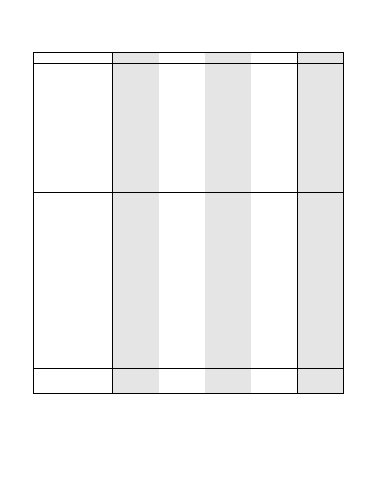
FRIGIDAIRE MODEL SPECIFICATIONS
Model FAS156N1A FAS184N2A FAS185N2A FAS186N2A FAS226N2A
Chassis Type
Capacity Features
BTU - Cooling
BTU - Heating
Moisture Removal
EER
Electrical Information
Voltage
Amps - Cooling
Amps - Heating
Watts - Cooling
Watts - Heating
Fuse/Breaker (Amps)
Receptacle Code
Wiring Diagram
Page #
Air Flow System
Capacitor-µ farads
Fan Motor Mfg.
Fan Motor Number
RPM/CMP (EVAP)
High
Medium
Low
Heat Only
Refrigeration System
Compressor Mfg.
Compressor Number
Compressor Type
Overload Protector
Capacitor-µ farads
Refrigerant Charge
Restrictor Tube
Thermostat Type
Installation Instructions
Kit Type
Part Number
Heavy Duty
Top Control
15100
-
3.5
10.7
115
12.5
-
1415
-
15
A
309902101
17
10/370
Heshan
309630615
980/530
-
810/400
-
LG
QK191CAB
Rotary
A363784
60/370
42
A112129
Electronic
A
309000906
Heavy Duty
Top Control
18000/17800
-
5.3
9.7
230/208
8.5/9.0
-
1860/1840
-
15
C
309902101
17
6/440
Heshan
309630613
975/500
-
775/400
-
LG
QJ258KAB
Rotary
A363771
25/440
31.75
A112138
Electronic
A
309000906
Heavy Duty
Top Control
18500/18200
-
5.5
10.7
230/208
7.8/8.5
-
1730/1700
-
15
C
309902101
17
6/450
Heshan
309630613
1000/480
-
800/380
-
LG
QJ250KBA-6A
Rotary
A363789
35/450
36
A112115
Electronic
A
309000906
Heavy Duty
Top Control
18500/18200
-
5.5
10.7
230/208
7.8/8.5
-
1730/1700
-
15
C
309902101
17
6/450
Heshan
309630613
1000/480
-
800/380
-
LG
QJ250KBA-6A
Rotary
A363789
35/450
36
A112115
Electronic
A
309000906
Heavy Duty
Top Control
22000/21600
-
6.5
9.4
230/208
10.5/11.4
-
2340/2300
-
15
C
309902101
17
7.5/450
Heshan
309630614
1115/550
-
925/470
-
LG
QP306KBA
Rotary
Internal
40/450
38.5
A112114
Electronic
A
309000906
Control Thermostat
Location Diagram
Condenser Fan and
Evaporator Blower
Location Diagram
Page 12 Page 12 Page 12 Page 12 Page 12
Page 14 Page 14 Page 14 Page 14 Page 14
4
Page 5
FRIGIDAIRE MODEL SPECIFICATIONS
Model FAS256N2A FAS296N2A FAH085N1T FAH08EN1T FAH105N1T
Chassis Type
Capacity Features
BTU - Cooling
BTU - Heating
Moisture Removal
EER
Electrical Information
Voltage
Amps - Cooling
Amps - Heating
Watts - Cooling
Watts - Heating
Fuse/Breaker (Amps)
Receptacle Code
Wiring Diagram
Page #
Air Flow System
Capacitor-µ farads
Fan Motor Mfg.
Fan Motor Number
RPM/CMP (EVAP)
High
Medium
Low
Heat Only
Refrigeration System
Compressor Mfg.
Compressor Number
Compressor Type
Overload Protector
Capacitor-µ farads
Refrigerant Charge
Restrictor Tube
Thermostat Type
Installation Instructions
Kit Type
Part Number
Heavy Duty
Top Control
25000/24700
-
7.6
9.4
230/208
12.0/13.0
-
2660/2630
-
20
D
309902101
17
7.5/450
Heshan
309630616
1145/590
-
925/470
-
LG
QP348KBB
Rotary
Internal
40/450
40.5
A112153
Electronic
A
309000906
Heavy Duty
Top Control
28500/28000
-
8.6
8.5
230/208
15.0/16.3
-
3365/3300
-
30
E
309902101
17
7.5/450
Heshan
309630616
1145/570
-
960/475
-
LG
QP425KAA
Rotary
Internal
45/450
41.3
A112156/57-59
Electronic
A
309000906
Builder Line Builder Line Builder Line
8000
-
1.8
9.4
115
7.5
-
850
-
15
A
309201101
16
10/370
Welling
309647503
1130/280
950/230
800/190
-
Matsushita
2R11S3R126A6A
Rotary
309205101
35/370
18.7
A112116
Electronic
T
309636002
8000
4200
1.8
9.4
115
7.5
12
850
1250
15
A
309201102
16
10/370
Welling
309647503
1130/280
950/230
800/190
-
Matsushita
2R11S3R126A6A
Rotary
309205101
35/370
18.7
A112116
Electronic
T
309636002
10000
-
2.8
9.4
115
10
-
1065
-
15
A
309201101
16
10/370
Welling
309647503
1130/280
950/240
800/210
-
LG
QK141CCA
Rotary
A363785
50/370
20.5
A112129
Electronic
T
309636002
Control Thermostat
Location Diagram
Condenser Fan and
Evaporator Blower
Location Diagram
Page 12 Page 12 Page 12 Page 12 Page 12
Page 14 Page 14 Page 14 Page 14 Page 14
5
Page 6

FRIGIDAIRE MODEL SPECIFICATIONS
Model FAH105N2T FAH10EN2T FAH124N2T FAH12EN2T FAK083N7V
Chassis Type
Capacity Features
BTU - Cooling
BTU - Heating
Moisture Removal
EER
Electrical Information
Voltage
Amps - Cooling
Amps - Heating
Watts - Cooling
Watts - Heating
Fuse/Breaker (Amps)
Receptacle Code
Wiring Diagram
Page #
Air Flow System
Capacitor-µ farads
Fan Motor Mfg.
Fan Motor Number
RPM/CMP (EVAP)
High
Medium
Low
Heat Only
Refrigeration System
Compressor Mfg.
Compressor Number
Compressor Type
Overload Protector
Capacitor-µ farads
Refrigerant Charge
Restrictor Tube
Thermostat Type
Installation Instructions
Kit Type
Part Number
Builder Line Builder Line Builder Line Builder Line Slider
Casement
10000/9800
-
2.8
9.4
230/208
4.7/5.1
-
1060/1045
-
15
C
309201101
16
6/450
Welling
309647501
1130/280
1010/240
880/210
-
LG
QK141KBE
Rotary
A363786
30/450
18.4
A112145
Electronic
T
309636002
10000/9800
10600/8600
2.8
9.4
230/208
4.7/5.1
15.5/14
1060/1045
3450/2800
20
D
309201102
16
6/450
Welling
309647501
1130/280
1010/240
880/210
-
LG
QK141KBE
Rotary
A363786
30/450
18.4
A112145
Electronic
T
309636002
12000/11700
-
3.6
9
230/208
5.9/6.4
-
1335/1300
-
15
C
309201101
16
7.5/450
Welling
309647502
1280/300
1130/260
975/230
-
LG
QK164KBC
Rotary
A363788
30/450
22.6
A112119
Electronic
T
309636002
12000/11700
10600/8600
3.6
9
230/208
5.9/6.4
15.5/14
1335/1300
3450/2800
20
D
309201102
16
7.5/450
Welling
309647502
1280/300
1130/260
975/230
-
LG
QK164KBC
Rotary
A363788
30/450
22.6
A112119
Electronic
T
309636002
8000
-
2.2
10.5
115
6.7
-
760
-
15
A
A232012
15
5/370
Heshan
309646002
1120/240
1000/210
940/190
-
Matsushita
2R11S3R126A2A
Rotary
309205101
35/370
20.11
A112124
Bulb
V
309625802
Control Thermostat
Location Diagram
Condenser Fan and
Evaporator Blower
Location Diagram
Page 12 Page 12 Page 12 Page 12 Page 11
Page 14 Page 14 Page 14 Page 14 Page 13
6
Page 7

FRIGIDAIRE MODEL SPECIFICATIONS
Model FAK103N1V FAK123N1V
Chassis Type
Capacity Features
BTU - Cooling
BTU - Heating
Moisture Removal
EER
Electrical Information
Voltage
Amps - Cooling
Amps - Heating
Watts - Cooling
Watts - Heating
Fuse/Breaker (Amps)
Receptacle Code
Wiring Diagram
Page #
Air Flow System
Capacitor-µ farads
Fan Motor Mfg.
Fan Motor Number
RPM/CMP (EVAP)
High
Medium
Low
Heat Only
Refrigeration System
Compressor Mfg.
Compressor Number
Compressor Type
Overload Protector
Capacitor-µ farads
Refrigerant Charge
Restrictor Tube
Thermostat Type
Installation Instructions
Kit Type
Part Number
Slider
Casement
10000
-
2.8
9.5
115
9.6
-
1050
-
15
A
A232012
15
15/370
Heshan
309646001
1400/305
1230/260
1050/210
-
LG
QK134CCA
Rotary
A363785
50/370
20.46
A112137
Bulb
V
309625802
Slider
Casement
12000
-
3.6
9.5
115
11.5
-
1260
-
15
A
A232012
15
15/370
Heshan
309646001
1400/305
1230/260
1050/210
-
LG
QK164CCA
Rotary
A363776
50/370
23.28
A112104
Bulb
V
309625802
Control Thermostat
Location Diagram
Condenser Fan and
Evaporator Blower
Location Diagram
Page 11 Page 11
Page 13 Page 13
7
Page 8

Compressor Overload Data
Part# Used With Compressor Supplier Part#
309260303 2R11S3R126A6A MRA98705
A363785 QK134CCA MRA12061-12056
A363785 QK141CCA MRA12061-12056
A363776 QK164CCA MRA12053-12057
A363784 QK191CAB MRA4720-12057
A363786 QK141KBE MRA12054-12056
A363788 QK164KBC MRA12124-12056
A363771 QJ258KAB MRA12044-12057
A363789 QJ250KBA MRA12107-12057
*Terminal to overload must withstand 10 pounds pull test.
Opening Temp
C°± 5 C°
150 61 50.5
150 61 50.5
150 61±9 C° 41.5
150 69 50.3
155±7 C° 69 14.5
155 69 19.0
160 61 29.0
150 69 27.3
Closing Temp
C°± 11 C°
Short Time Trip at 25 C°
Test Amp Opening Time-Sec
6-16
6-16
6-16
2-12
6-16
6-16
6-16
6-16
Restrictor Tube Data
Style#
Internal Diameter
Color Code
Length O.D.
I.D PSIG
A112114 Red 35.00 0.112 0.059 10 0.294 0.318
A112115 Red 40.00 0.112 0.059 10 0.274 0.296
A112129 Purple 45.00 0.097 0.046 25 0.261 0.283
A112138 Black 33.00 0.099 0.049 20 0.304 0.330
A112153 Blue 37.50 0.125 0.064 10 0.227 0.247
A112156 Black 38.19 0.099 0.049 20 0.352 0.382
A112157 Black 19.69 0.099 0.049 20 0.181 0.197
A112158 Black 23.62 0.099 0.049 20 0.218 0.236
A112159 Black 29.13 0.099 0.049 20 0.268 0.291
CFM Dry Air
Minimum Maximum
A112124 White 45.00 0.106 0.054 20 0.346 0.374
A112137 Purple 51.18 0.097 0.046 25 0.248 0.268
A112104 Black 45.00 0.099 0.049 20 0.258 0.280
A112116 White 40.00 0.106 0.054 20 0.366 0.396
A112129 Purple 45.00 0.097 0.046 25 0.261 0.283
A112145 Black 37.00 0.099 0.049 20 0.288 0.312
A112119 Black 35.00 0.099 0.049 20 0.296 0.320
8
Page 9

Receptacle Outlet Codes
Code A
115 Volts - 15 Amps
NEMA 5 - 15 TYPE
Code D
230 Volts - 20 Amps
NEMA 6 - 20 TYPE
Code B
115 Volts - 20 Amps
NEMA 5 - 20 TYPE
Power Supply Cord with
3-prong Grounding Plug
Code C
230 Volts - 15 Amps
NEMA 6 - 20 TYPE
Code E
230 Volts - 30 Amps
NEMA 6 - 30 TYPE
Grounding Type
Wall Receptacle
9
Page 10

Product Dimensions
Heavy Duty Slide Out Top Control
10
Page 11

Control Thermostat Location Diagrams
Slider Casement
Compact Rotary Control
Compact Electronic Control
Intermediate Rotary
Top Control
11
Page 12

Control Thermostat Location Diagrams
A
2004 Heavy Duty Thermostat Locations
15.1K 18K 22 K18.5K 28.5K25K
Freeze thermistor and freeze thermistor holder.
2004 Builder Thermostat Locations
8K and 10K12K
Freeze the rmistor and free ze
thermistor holder.
3.94"
Bracket-Evap
B
B
7.87"
ir thermistor and air thermistor h older(Place
3.75"
A
A
Section A-A
between 9th & 10th
rows up from t he bottom)
fin
Section B-B
insulation
fourth row from bottom
third row from bottom
second row from bottom
first row from bottom
12
fin
2004 Slider
Thermostat
Locations
fin
9th Row from bott om
8th Row from bott om
7th Row from bott om
6th Row from bott om
Retaining Clip
Retaining Clip
Page 13

Fan and Blower Location Diagrams
Compact
Slider Casement
18.5”
No Side Louvers
13
Page 14

Fan and Blower Location Diagrams
Heavy Duty
Top Control
COND. FAN
BLOWER WHEEL
To be fully seated
against motor shaft.
(bottom out on shaft)
BULKHEAD ASSY.
CLAMP SCREW
TORQUE TO
22-27 IN.LBS.
CONDENSER FAN
To be fully seated
against motor shaft.
(bottom out on shaft)
Motor Shaft
Clamp Clamp
Evaporator Side Condenser Side
Motor
SHROUD
& SEAL
ASSY.
SCREW (3) SHROUD/
BULKHEAD ASSY.
TORQUE TO 25 IN.LBS.
CLAMP
TORQUE TO
15-20 IN. LBS.
BLOWER
WHEEL
.300
FAN CLAMP
PUSH FAN BLADE
TILL END
OF FLAT
COND. FAN
.370
REF.
SLINGER RING
SHROUD
.560
SCROLL
.380
AIR SYSTEM
(H/D T/C)
Heavy Duty Side Discharge
14
Page 15

Wiring Diagrams
A232012
R
BL
BK
PLAIN (BROWN) - ORDINAIRE (BRUN)
(VENTILATEUR LENT)
(VENTILATEUR MOYEN)
(VENTILATEUR RAPIDE)
(REFROIDISSEMENT ÉLEVÉ)
(REFROIDISSEMENT MOYEN)
(REFROIDISSEMENT BAS)
BK
C
S
R
W
ALTERNATE INTERNAL
COMPRESSOR OVERLOAD
(AUTRE SURCHARGE
INTERNE DU COMPRESSEUR)
R
or (ou)
LO FAN
MED FAN
HI FAN
OFF
(ARRÊT)
HI COOL
MED COOL
LO COOL
RIBBED - BLUE
(RAYE - BLEU)
COLOR CODE
BL - BLUE (BLEU)
G - GREEN (VERT)
BK - BLACK (NOIR)
BR - BROWN (BRUN)
R - RED (ROUGE)
W - WHITE (BLANC)
A
L1
GND
(TERRE)
W
2
4
1
3
G
1
3
ROOM THERMOSTAT
4
2
(SÉLECTEUR)
SELECTOR SWITCH
COMPRESSOR
(COMPRESSEUR)
S
W
(THERMOSTAT DE LA PIÉCE)
BK
COMPRESSOR
OVERLOAD
(SURCHARGE DU
COMPRESSEUR)
BK
C
R
R
COMPRESSOR
CAPACITOR
(CONDENSATEUR
DU COMPRESSEUR)
START
ASSIST
(DÉMARREUR)
W
BR
FAN CAPACITOR
(CONDENSATEUR
DU VENTILATEUR)
FAN MOTOR
(MOTEUR DU
VENTILATEUR)
15
Page 16

A
RR
A
R
2
0
4
6
1
8
Heater Relay(Relais Du
Chauffage Electrique)
OR
OR
BK
BK
Heater(Chauffage
Electrique)
DAHT(Sonde Du
Chauffage
Electrique)
Eva p
Sensor(Sonde Anti Givre)
Room
Sensor(Sonde D' Ambiance)
G
(Vert)
HT
Relay
(Relais)
Connector(Connecteur)
OR
OR
GND
Wiring Diagrams
FH
Relay
(Relais)
Plain
(Brown)
Ord inai re(Bru n)
Ribbed
(Blue)
Raye(Bleu)
FM
Relay
(Rel ais)
AC- N
FL
Relay
(Relais)
4
3
W
Compressor
capacitor
(Condensateur Du
Compresseur)
BK
BK
SR
Compressor
(Compresseur)
N2
N1
Compressor
Relay(Relais
Du
Compresseur)
Compressor Overload
(Surcharge Du
Compresseur)
C
WOR Y
(O U)
R
Fan motor capacitor
(Condensateur Du
Ventilateur)
BR
MED
BL
HI
BK
Fan motor
(Moteur Du
Ventilateur)
R
LO
R
BK=Black(Noir)
BL=Blue(Bleu)
BR= Brown(B run)
G=Green(Vert)
OR=Orange(Orange)
R=Red(Rouge)
W=White(Blanc)
Y=Yellow(Jaune)
BK
C
S
R
W
lternate In ternal Overl oad
Compr essor
(Autre Surcharge
Interne D u Compresseur)
309201102/02
R
Evap
Sensor(Sonde Anti Givre)
Room
Sensor(Sonde D' Ambiance)
Connector(Connecteur)
G
GND
(Vert)
FH FL
FM
Relay
Relay
(Relais)
(Relais)
Plain
(Br own)
Ordinaire(Brun)
Ribbed
(Blu e)
Raye(Bleu)
AC-N N1
Relay
(Relais)
4
3
S
W
Compressor
(C ompre sseur )
Compressor
capacitor
(Condensateur Du
Compresseur)
N2
Compressor
Relay(Relais
Du
Compresseur)
Compressor Overload
(Surcharge Du
Compresseur)
R
R
Fan motor capacitor
(Condensateur Du
Ven t il at eur )
BR
MED
BL
HI
BK
Fan motor
(Moteur Du
Ven t il at eur )
R
LO
R
BK= Black(Noi r)
BL=Blue(Bleu)
BR =Bro wn(B run )
G=Green(Vert)
R=Red(Rouge)
W=White(Blanc)
Y=Yellow(Jaune)
BK
C
S
R
W
lternate Internal Overload
Compressor
(Autre Surcharge
Interne Du C ompresseur)
309201101/02
R
16
Page 17

Wiring Diagrams
(
)
J3210
Connector (Connecteur)
Evap
Sensor (Sonde
Anti Givre)
Room
Sensor
(Sonde D'
Ambiance)
Ion.
3
4
Compressor Relay (Relais Du
Compresseur)
Ionizer(Ion)
(Optional)
(Facultatif)
G
(Vert)
GND
Plain
(Brown)
Ordinaire(Brun)
Ribb ed
(Blue)
Raye( Bleu)
Fan(Ventilateur)
N
BK
BK
C
R
S
W
Compressor
(Compresseur)
Compressor
capacitor
(Condensateur Du
Compresseur)
Compressor Overload
(Surcharge Du
Compresseur)
WOR Y
(OU)
R
Fan motor capacitor
(Condensateur Du
Ventilateur)
BR
BK
G
(Vert)
GND
Fan motor
(Moteur Du
Ventilateur)
R
BK=Black(Noir)
BL=Blue(Bleu)
BR=Brown(Brun)
G=Green(Vert)
R=Red(Rouge)
W=White(Blanc)
Y=Yellow
Jaune
BK
C
S
R
W
Alternate Internal Ove rload
Compressor
(Autre Surcharge
Interne Du Compresseur)
R
309902101/01
17
Page 18

ROOM AIR CONDITIONERS TROUBLESHOOTING
CAUTION: Review Safe Servicing Practices in
the front of this manual before attempting
diagnostic procedures and repairs.
AIR CONDITIONER VOLTAGE LIMITS
ETALPEMAN
GNITAR
CAV511CAV5.301CAV5.621
CAV032CAV702CAV352
032/802CAV5.791CAV352
AIR CONDITIONER VOLTAGE LIMITS
Low voltage is a common cause of trouble in the operation
of any room air conditioner.
Improper voltage may cause one or more of the following
problems:
1. Unit will not start.
2. Compressor motor cycling on motor protector.
3. Premature failure of motor protector.
4. Blown fuses.
5. Premature failure of compressor or fan motor.
6. Noticable dimming of lights when air conditioner is
running.
7. Evaporator icing. Low voltage may reduce fan speed
resulting in inadequate air flow over evaporator, thereby
allowing it to ice up.
MUMINIM MUMIXAM
Low voltage can also be the direct result of inadequately
wired circuits, extension cords, or loose fuses and
connections to the power supply. Voltage may also be a
general condition in the area (a responsibility of the power
company).
All units will start and run on the minimum voltage stated
in the chart to the left, and will perform satisfactorily if the
voltage remains constant. Low voltage caused by defective
wiring will not remain constant under load.
To test for low voltage, use a reliable meter with sufficient
capacity to measure the required voltage. Take
measurements at the electric power entry point and at the
electric outlet serving the air conditioner. Take readings
with the unit off, while the unit is starting, and again while
the unit is running. The lowest reading should not drop
below the lowest value listed in the chart.
HIGH VOLTAGE
High voltage can be equally troublesome, causing motors
to overheat, cycle on their protectors, or break down
electrically. This problem can only be solved by the power
company.
ELECTRONIC CONTROL
This control is not repairable. If any component in the
control is defective, the entire control must be replaced.
IMPORTANT NOTICE: Repair or replace any
malfunctioning line voltage component before testing
or replacing the electronic control. DO NOT assume a
service problem is directly caused by the electronic
control system. A line voltage component (including
power cord and wiring) that has opened, shorted,
grounded or otherwise malfunctioned, may have created
a service problem.
SYMPTON POSSIBLE CAUSE
Fan motor will not run. 1. No power.
Fan motor runs intermittently. 1. Cycle on motor protector.
2. Power supply cord.
3. Selector switch.
4. Energy saving switch (if applicable).
5. Electronic control (if applicable).
6. Wire disconnected or connection loose.
7. Capacitor. (Discharge capacitor before testing.)
8. Defective fan motor windings.
9. Will not rotate. Fan blade hitting shroud or blower
wheel hitting scroll. (Motor cycles on overload.)
18
Page 19

SYMPTON POSSIBLE CAUSE
Fan motor noisy. 1. Condenser fan blade or evaporator blower
wheel.
2. Loose power clamp or set screw.
3. Worn bearings.
4. Grommets (if applicable).
Compressor will not run, but fan motor runs. 1. Voltage.
2. Wiring.
3. Selector switch.
4. Temperature control.
5. Capacitor. (Discharge capacitor before testing.)
6. Compressor.
7. Motor protector (external).
8. Motor protector (internal).
9. Electronic control (if applicable).
10. Hard starting.
Compressor cycles on motor protector. 1. Voltage.
2. Motor protector (external).
3. Motor protector (internal).
4. Fan motor.
5. Condenser air flow restriction.
6. Condenser fins damanged.
7. Capacitor.
8. Wiring.
9. Refrigerant system.
Insufficient cooling. 1. Low capacity.
2. Air filter.
3. Exhaust door open.
4. Unit undersized.
Excessive noise. 1. Evaporator blower wheel.
2. Condenser wheel.
3. Copper tubing.
4. Compressor internal noise.
5. Fan motor.
Excessive water or condensation. 1. Unit operating under extremely high humidity
conditions.
No cooling. 1. Refrigerant leak.
Unit is cooling but room is not cool. 1. Amps and watts.
2. Sealed refrigeration system.
Wattage decreases slowly until abnormally low. 1. Undercharged, restricted strainer or plugged
restrictor tube.
Wattage decreases immediately. 1. No refrigerant.
2. Compressor defective.
Wattage continuously high. 1. Refrigerant overcharge.
19
Page 20

SYMPTON POSSIBLE CAUSE
Evaporator coil partially frosted. 1. System low on refrigerant.
Evaporator completely iced. 1. Low outside temperature.
No heat. 1. No power.
2. Selector switch position.
3. Temperature control position.
4. Fan motor.
5. Heating element.
6. Selector switch.
7. Temperature control.
8. Terminals and connectors.
Fan motor will not rotate during heat cycle. 1. Thermostatic drain valve. (Water level control, if
(Heat/Cool models only.) applicable.)
20
 Loading...