

Frigidaire FAS226R2A - Heavy Duty Room 22, 000 BTU Air Conditioner FAS226, FAS Series, FAM Series Installation Instructions Manual
Installation Instructions
For Heavy Duty (FAS Models) and
Median (FAM Models) Air Conditioners
Please read ALL instructions before installing.Two people are
recommended to install this product.If a new electrical outlet
is required,have the outlet installed by a qualified electrician
before installing unit. See#5 in Preliminary Instructions
following.
Preliminary instructions
Do the following before starting to install unit.See illustrations
below.
with this air conditioner are made to install in a wooden
Check dimensions of your unit to determine model type:
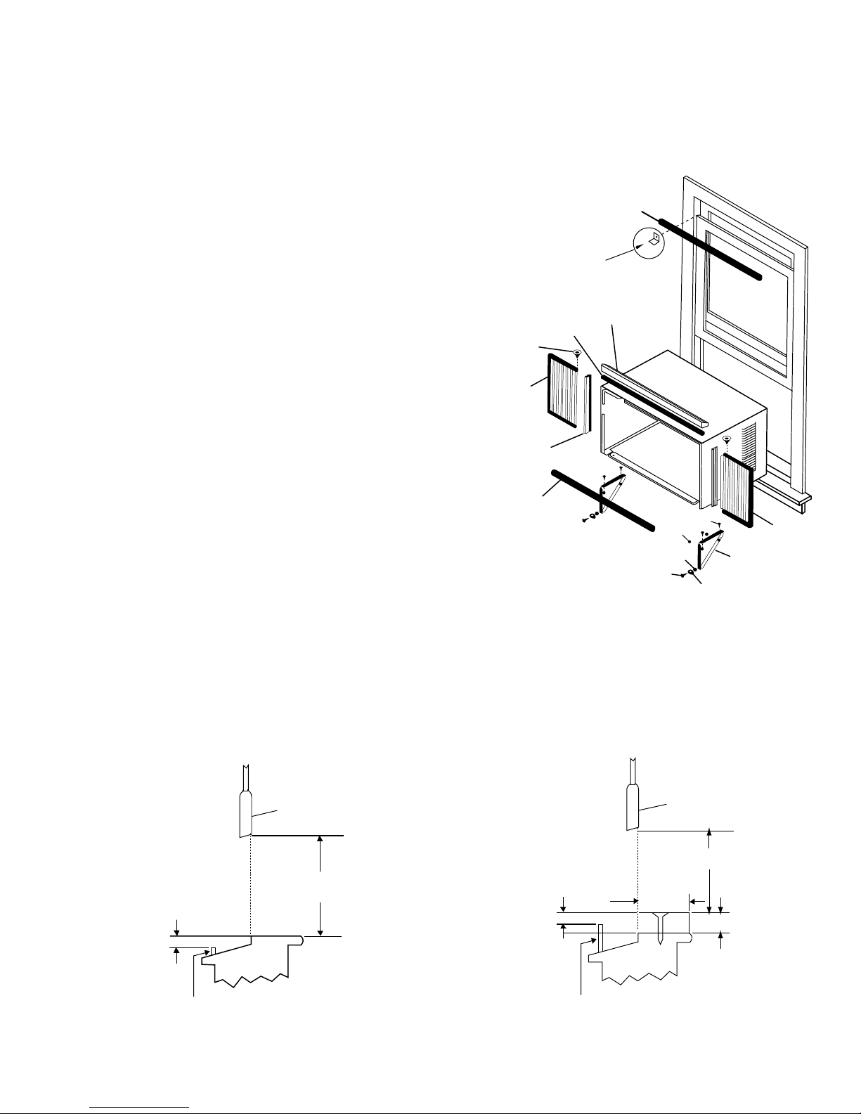
1. Check window opening size - the mounting parts furnished
sill double-hung window.The standard parts are for
window dimensions listed above.Open sash to a minimum
of 19"(483mm). (FIG. 1)
2. Check condition of window - all wood parts of window
must be in good shape and able to firmly hold the needed
screws.If not, make repairs before installing unit.
3. Check your storm windows - if your storm window
frame does not allow the clearance required, correct by
adding a piece of wood as shown in FIG.2, or by removing
storm window while room air conditioner is being installed.
(continued)
Unit Height:
Unit Width:
Min. Window Opening:
Min. Window Width:
Max. Window Width:
Heavy duty (FAS)
Median (FAM)
18.5/8"
17.5/8"
26 1/2"
23 1/2"
18 1/2"
26 1/2"
40 1/2"
19"
31"
43"
FIG. 1
FIG. 2
SASH
19" MIN
1/2" MIN
STORM WINDOW FRAME OR
OTHER OBSTRUCTION
SASH
1/2" MIN
19" MIN
STORM WINDOW FRAME OR
OTHER OBSTRUCTION
1 1/2" MIN
BOARD THICKNESS AS
REQUIRED, ALONG
ENTIRE STOOL, FASTEN
WITH TWO NAILS OR
SCREWS.
1
SEAL-BOTTOM RAIL TO UNIT
SIDE RETAINER
FRAME
ASSEMBLY
(LEFT)
WASHER HEAD
LOCKING SCREW
FOAM GASKET
TOP ANGLE
FRAME
ASSEMBLY
(LEFT)
SAFETY LOCK AND
3/4" LONG HEX HEAD
SCREW
1/2" LONG
SCREWS AND
LOCKNUTS
LOCKNUT
3/4" LONG
FLAT HEAD
BOLT
WINDOW SUPPORT
BRACKET
WINDOW SASH SEAL
SILLANGLE
BRACKET
P/N 66121625
4. CHECK FOR ANYTHING THAT COULD BLOCK
AIRFLOW - check area outside of window for things
such as shrubs, trees, or awnings. Inside, be sure
furniture, drapes, or blinds will not stop proper air flow.
5. Check the available electrical service - power supply must
be the same as that shown on the unit serial nameplate.
(See Owner's Guide for serial plate location.)Power cord
is 48"long. Be sure you have an outlet near.
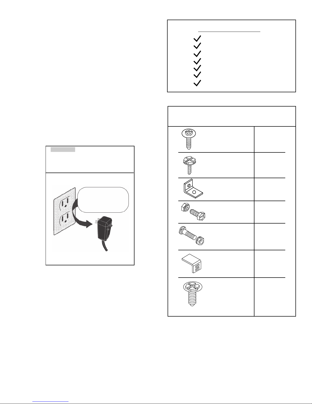
All models have a 3-prong service plug to provide proper
service and safe positive grouding. Do not change plug in
any way. Do not use an adapter plug. If your present wall
outlet does not match your plug, call a qualified electrician
to make the needed change.
a large flat blade screwdriver
tape measure
adjustable wrench or pliers
pencil
Level
Socket wrenches
Phillips screwdriver
Tools Required
Hardware (in plastic bag)
6. Carefully unpack air conditioner - remove all packing
material. Protect floor or carpet from damage. Two
people should be used to move and install unit.
Avoid fire hazard or electric
shock. Do not use an extension cord or an
adaptor plug. Do not remove any prong from
the power cord.
WARNING
Grounding type wall
receptacle
Do not, under any
circumustances, cut,
remove, or bypass the
grounding prong.
Power supply cord
with 3-prong grounding
plug and current
detection device
Washer Head
Locking Screw
For window panels
3/4" Long Hex-
Head Screw
3
2
Qty.
Safety Lock
1/2" Long Screw
and locknut
3/4" Long Flat
Head Bolt and
Locknut
Sill Angle Bracket
1
4 ea.
2 ea.
2
10
Long hex-head
locking screw for
top angle, side
retainer 5/16"
Long
2
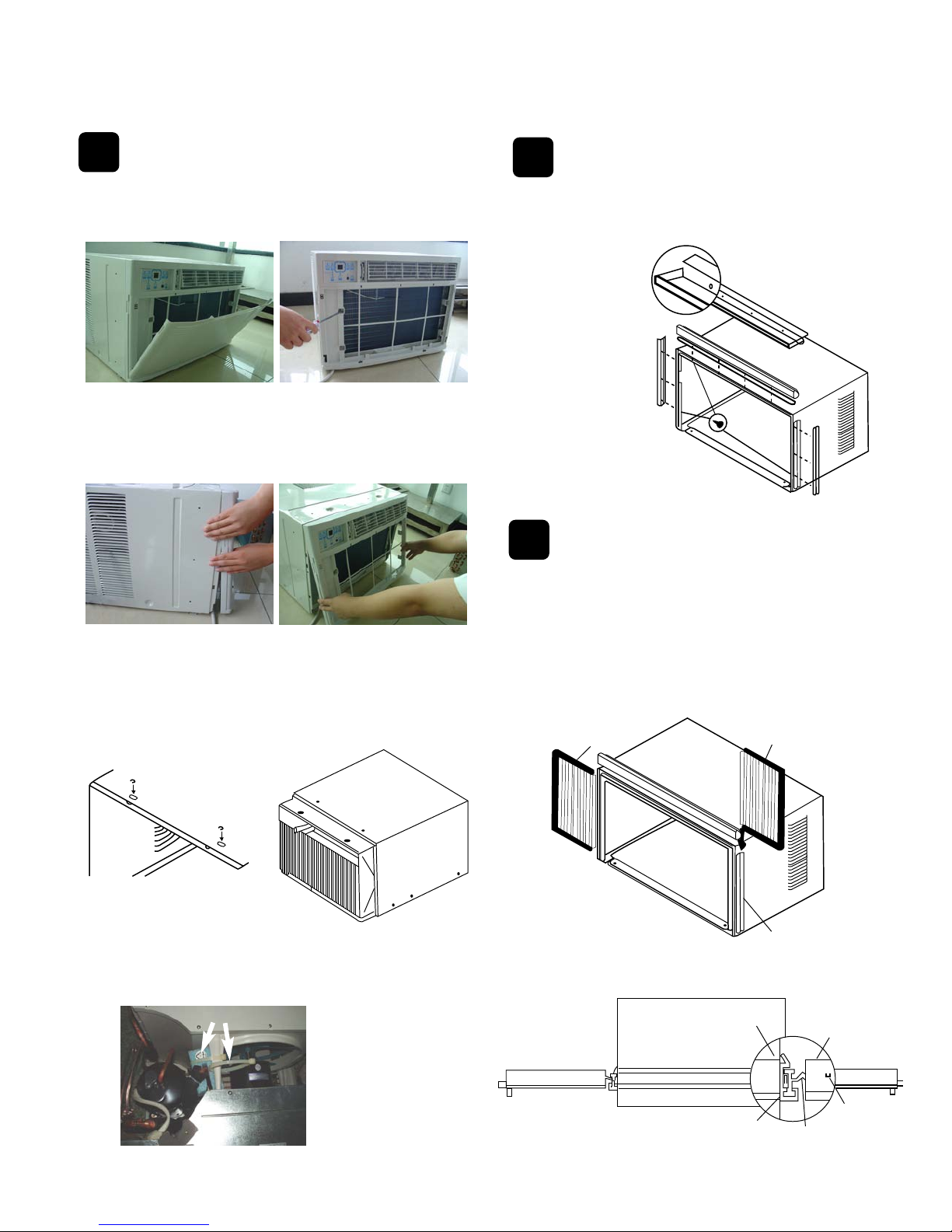
Remove Chassis
Install Top Angle
and Side Bracket
1
2
Window Mounting
1. Pull down front panel and remove filter. (See FIG. 1).
2. Lift front upwards and place to one side.
1. Attach foam gasket to top angle above holes as
shown in FIG. 6.
3. Locate the four front screws and remove. These screws will
be needed to re-install the front later. (See FIG.2)
4. Pry away front from cabinet sides as per photo (see FIG.3)
5. Gently lift front off unit and place to one side (See FIG.4).
2. Install top
angle and
side retainers
to cabinet as
shown in FIG. 6.
FIG. 6
6. Remove shipping crews from top of unit and also on the side
by the base if installed.
7. Hold the cabinet while pulling on the base handle, and carefully remove the unit.
8. Add two foam inserts to holes in top of cabinet where
shipping screws were removed from.
Assemble Window
Filler Panels
1. Place cabinet on floor, a bench, or a table.
2. Slide "I" section of window filler panel into side retainer
on the side of the cabinet (see Figures 7-8). Do both
sides.
FIG. 7
3
PLASTIC
FRAME
WINDOW FILLER
PANEL
SIDE
RETAINER
FIG. 8
9. Your unit may come with internal packaging.THIS
PACKAGING MUST BE REMOVED PRIOR TO
INSTALLING THE AIR CONDITIONER BACK
INTO THE CABINET. (See FIG. 5)..
AIR CONDITIONER
CABINET
TOP
VIEW
PLASTIC
FRAME
"I" SECTION
WINDOW
FILLER
PANEL
LOCKING
SCREW
HOLE
3
FIG. 3
FIG. 4
FIG. 1
FIG. 5
Internal Packaging
FIG. 2
 Loading...