

Page 1

OWNER'S GUIDE
READ AND SAVE THESE INSTRUCTIONS
AIR CONDITIONER
ROTARYCONTROL
P/N 309000816 (9903)
Page 2

ROOM AIR CONDITIONER WARRANTY
Your product is protected by this warranty
Your appliance is warranted by White Consolidated industries, Inc WCI has authorized Frigidaire Consumer Services and their authorized servicers to
perform service under this warranty WCI authorizes no one else to change or add to any of these ob ga ons under this warranty. Any obligations for
service and parts under this warranty must be performed by Frlgidaqe Consurner Services or an authorized Frigidaire servicer
WARRANTY
PERIOD
FUELONE-yEAR One year from originaF Pay all costs for repairing or replacing any parts of this
WARRANTY lurchasedate appliance which prove to be defective in materials or
uMFrED 2ND - 5TH Second through fifth years Diagnostic costs and any removal, transportation
YEAR WARRANTY fromodginalpurchasedate. Repair or replace any parts in the Sealed Refrigeration and reinslallation costs which are required because
(Sealed System) System (¢omp(essor, cor_denser, evaporator and tubing) ofservlce Eostsforlabor. parts and transportation
UMITED Time pe_ods li_ed above¸
WARRANTY All of the provisions of the full and limited warranties above Costs of the techniPan s travel to the home and any
(Applicable to the a nd the exclusions listed below apply costs for pick up and delivery of the appliance required
State of Alaska) because of service
*NORMAL
RESPONSIBIUTIES
OF THE CONSUMER
EXCLUSIONS
IF YOU NEED SERVICE
This warranty applies only to products in ordinary household use, and the consumer is responsible for the
items listed below:
1. Proper use of the appliance in accordance with instructions provided with the product.
2 Proper installation by an authorized servicer in accordance with instructions provided with the appliance and in
accordance with all local plumbing, electrical and/or gas codes
3 Proper connection to a grounded power supply of sufficient voltage, replacement of blown fuses, repair of loose
connections or defects in house wiring.
4. Expenses for making the appliance accessible for servicing, such as removal of trim, cupboards, shelves, etc., which are
not a part of the appliance when it was shipped from the factory.
5 Damages to finish after installation.
6 Replacement of ]ight bulbs and/or fluorescent tubes (on models with these features).
This warranty does not cover the following:
1 CONSEQUENTIAL OR _NCIDENTAL DAMAGES SUCH AS PROPERTY DAMAGE AND INCIDENTAL EXPENSES RESULTING
FROM ANY BREACH OF THIS WRITTEN OR ANY IMPLIED WARRANTY.
Note: Some 5tares do nrrt allow Ihe exclusion or limitation of itlcidental or Consequential damages, so this limitation or
exclusion may not apply to you.
2 Service calls which do not involve nnagunction er defects in workmanship or material or for appliances not in ordinary
household use The consumer shall pay for such service tails.
3 Damages caused by services performed by perso_s other than authorized Frigidaire servicers; use of parts other than
Frigidaire Genuine Renewal Parts: obtained from persons other than such servicers; or external causes such as abuse,
misuse, inadequate power supply or acts of God
4. Products with original serial numbers that have been removed or altered and cannot be readily determined.
Keep your bill of sale, delivery slip, Or some other appropriate payment record• The date on the bill establishes the warranty
perlod should service be required If service is performed, it is in your best interest to obtain and keepailreceipts. This
written warranty gives you specific legal rights. You may also have other rights that vary from state to state• Service under
this warranty must be obtained by followmg these steps, in order:
I. Contact Frigidaire Consumer Services or an authorized Frigidaire servicer.
2. If there is a question as to where to obtain service, contact our Consumer Relations Department at:
FRIGIDAIRE, THROUGH ITS AUTHORIZED
workmanship¸
proves to be defective in materials or workmanship other than with respect to the Sealed Refrigeration
SERVICERS. WILl=
Costs of service c_ that are listed u_Jer NORMAL
RESPONSIRIUTIES OF THE CONSUMER.*
System
THE CONSUMER WILL BE
RESPONSIBLE FOR:
Frigidaire Company
P.O. Box 212378
Augusta, GA 30917
BFRIG!D RE
800-444-4944
Product features or specifications as described or illustrated are subject to change without notice. All warranties are made by White
Consolidated industries. Inc This warranty applies only in the S0 states of the U S.A.. Puerto Rico and Canada.
Page 3
Product Registration
Record Your Model and Serial Numbers
Record in the space provided below the model and serial numbers. On most
models, the serial plate is located behind the left front louvers. Reading these
numbers may be easier by using a flashlight or by removing the cabinet front as
instructed under "Careand Cleaning." On somemodels, theserialplateislocated
on the outside of the cabinet.
Model No.
Serial No.
Register Your Product
The self-addressed PRODUCT REGISTRATIONCARD should be filled in completely,
signed and returned to the Frigidaire Company.
Contents
NOTE: This Owner's Guide provides
specific operating instructions for your
model. Usethe room air conditioner only
as instructed in this Owner's Guide.
These instructions are not meant to
cover every possible condition and
situation that may occur. Common sense
and caution must be practiced when
installing, operating, and maintaining
any appliance.
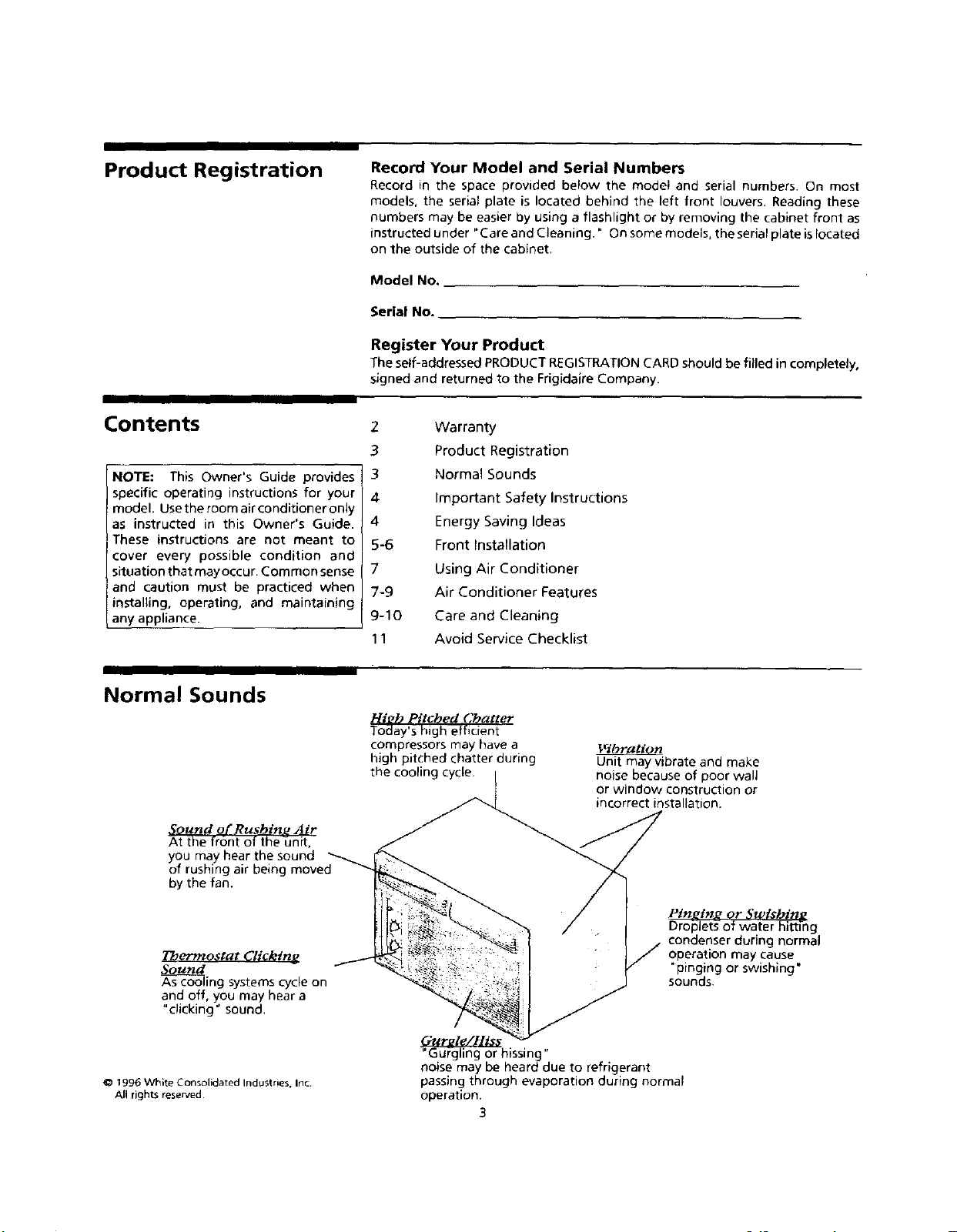
Normal Sounds
Sound of Rushing Air
At the front Of the unit,
you may hear the sound
of rushing air being moved
by the fan.
2 Warranty
3 Product Registration
3 Normal Sounds
4 Important Safety Instructions
4 Energy Saving Ideas
5-6 Front installation
7 Using Air Conditioner
7-9 Air Conditioner Features
9-10 Care and Cleaning
11 Avoid Service Checklist
Pli#h Pitched Chatter
Today's high efficient
compressors may have a
high pitched chatter during
the cooling cycle.
Unit may vibrate and make
noise because of poor walJ
or window construction or
incorrect installation.
272ermostat Clicktne
Souu_d
As cooling systems cycle on
and off, you may hear a
"cJicking + sound.
1996 VVhlte Consolidated Industries, lot
Atl rights reserved
"Gurgling or hissing"
ooise may be heard due to refrigerant
passing through evaporation during normal
operation.
3
Ptn_tn_ or Swt.chine
Droplets- of water hitting
condenser during normal
operation may cause
"pinging or swishing"
sounds.
Page 4

Important Safety
Instructions
Avoid fire hazard or
electric shock. Do not use an extension
cord or an adaptor plug. Do not remove
any prong from the power cord.
Grounding type
wall receptacle
under
Power supply
cord with 3- rong
grounding p_urg
Read all instructions before using this air conditioner.
For Your Safety
Do not store or usegasoline or other flammable vapors and liquidsin the vicinity of
this or any other appliance. Readproduct labelsfor flammability and other warnings.
P'I_[,VAV_,IlI_II_[€
Prevent Accidents
To reduce the risk of fire, electrical shock, or injury to persons when using your
air conditioner, follow basic precautions, including the following:
• Be sure the electrical service is adequate for the model you have chosen. This
information can be found on the serial plate, which is located either behind the
louvers or on the left side of the cabinet.
• If the air conditioner is to be installed in a window, you will probably want to
clean both sidesof the glass first. If the window isatriple-track type with ascreen
panel included, remove the screen completely before installation.
• Be sure the air conditioner has been securely and correctly installed according to
the separate installation instructions provided with this manual. Savethis manual
and the installation instructions for possible future use inremoving or reinstalling
this unit.
• When handling the air conditioner, be careful to avoid cuts from sharp metal fins
on front and rear coils.
Electrical Information
The complete electricalrating ofyour new room airconditioner isstated on the serial
plate. Refer to the rating when checking the electrical requirements.
• Be sure the air conditioner is properly grounded. To minimize shock and fire
hazards, proper grounding is important. The power cord is equipped with a
three-prong grounding plug for protection against shock hazards,
• Your air conditioner must be used in a properly grounded wall receptacle• If the
wall receptacle you intend to use is not adequately grounded or protected by a
time delay fuse or circuit breaker, have a qualified electrician install the proper
receptacle.
• Do not run air conditioner with outside protective cover in place This could result
in mechanical damage within the air conditioner•
• Do not use an extension cord or an adapter plug.
Energy Saving Ideas
• Do not block air flow inside with blinds, curtains or furniture;
or outside with shrubs, enclosures, or other buildings.
• The capacity of the room air conditioner must fit the room size for efficient and
satisfactory operation.
• Install the room air conditioner on the shady side of your home. A window that
faces north is best because it is shaded most of the day.
• Close the fireplace damper, floor and wall registers so cool air does not escape
up the chimney and into the duct work.
• Keep blinds and drapes in ot her windows closed during the sunniest part of the day.
• Clean the air filter as recommended in the section "Care and Cleaning."
• Proper insulation and weather stripping in your home will help keep warm air
out and cool air in.
• External house shading with trees, plants or awmngs will help reduce the air
conditioner's work load.
• Operate heat producing appliances such as ranges, washers, dryers and
dishwashers during the coolest part of the day.
4
Page 5

Front Installation
Installing Bottom Rail Seal
Vertical louver_ /Unit Cover
/
Horizontal
Louvers
Front Installation - Side Air Discharge
FIG.
Installing Bottom Rail Seal (some models)
Some models are shipped ina removable sleevethat must be positioned propedy for
safe and efficient sealing. Follow the Installationinstructions supplied. To installthe
Bottom Rail Seal, position the sealon top of the bottom rail, flush with the front edge
of the rail and in contact with the side seals.
Manual Vertical Louver Adjustment (side air discharge)
Complete this adjustment before installing front panel.
1. Adjust the vertical louversto the straight position by using the handle.
2. The dial plate and knobs are packed separately, To install them, refer to
Installing the Dial Plate and Front Frame section on the next page.
Front Installation - Some Side Air Discharge Models (FIG. 1)
Install the front panel with filter as follows;
1. Adjust the horizontal louvers to the straight position. Hold the front straight
until the vertical louver handle lines up between the bottom horizontal louver
and the discharge opening.
2. Press the front straight onto the cabinet until the holes in the flange of the
plastic front line up with the screw holes in the metal cabinet. Fasten the front
panel in place with the two screws provided.
Front Installation - Some Side Air Discharge Models (FIG. 2)
1. Positionthe top of the decorative front cover ontothe top flange of metal case
and then align the tabs on the front with slots in metal case.
2. Carefully pull down on the front cover to engage top tabs while pushing the
front cover over the metal case. To ensure proper alignment the side
locking tabs will "click" when the front cover isproperly installed.
Note: Power cord must be held in position inside metal case half-round relief
while sliding front cover over metal case.
3. Install the front cover retaining screw at the bottom of the unit.
Installing the Vent Control (on some models)
The vent control handle isincluded in the decorative front kit (Fig. 3), The handle
must be installed before the decorative front is attached. See illustration below.
Front Installation - Side Air Discharge
FIG. 2
1. Insert the handle with the "Etchings (Vent/Air)" facing to the left.
2. Slip the black door extension into the split at the end of the handle.
3. For ease of assembly, Pusg the handle in while pressing the door extension
against the foam until the two pieces lock together.
4. Move handle in and out to be sure vent is operating properly
FIG, 3
Page 6

Front Installation
(continued)
STEP 1: INSTALL DIAL PLATE AND BUTTONS OR KNOBS:
Installing Dial Plate and Front Frame
Some models require installation of the dial plate and the front panel of the air
conditioner included in a decorative kit. To assemble, follow these steps.
..... __
_ --
"_._ ! ri :"lit !I'! i!'i!il
Side Air Discharge
o Remove control knobs from front kit
(some models).
• Carefully remove protective film
from the front of the dial plate
(some models).
• Line up holes on dial plate with the
correct control stems and push dial
plate to control panel surface.
• While holding dial plate in place
install control knobs on protruding
stems.
STEP 2:
INSTALL FRONT FRAME TO UNIT.
Decorative Front
• Position the top of the decorative front over the top flange of the case, and align the tabs with the
slots in the case.
• As you install the front frame to the unit be sure the vent handle is positioned through the front in the proper
location.
• Carefully pull down on the front to engage the top tabs, while pushing the front over the case to
ensure proper alignment.
• The side tabs will "click" when front is seated.
• Install front retaining screw(s) at the bottom of the front (Fig. 1), or behind the filter handle (Fig. 2).
FIG 2
FIG. 1
6
Page 7

Using Air Conditioner
NOTE: Ifthe air conditioner isturned off,
wait 3 minutes before restarting. This I
allows pressure inside the compressor to !
equalize. Failure to follow these I
instructions may cause inefficient
operation.
To reduce the risk of fire, electdc shock, or inJury to persons, read the
IMPORTANT SAFETY iNSTRUCTIONS before operating this appliance
To begin operating the air conditioner, follow these steps:
1. Plug in the air conditioner. (To prevent electrical hazards, do not use an
extension cord or an adapter plug.)
2. Set the exhaust vent to the CLOSED position.
3. Set the thermostat to the highest number (coldest or cooler setting).
4. Set the selector control to the highest FAN or COOL setting (see below).
5. Adjust the louvers for comfortable air flow (see Air Directional Louvers).
6. Once the room has cooled, adjust the thermostat to the setting you find most
comfortable.
Review the "Air Conditioner Features" section for other settings.
Air Conditioner Features
OFF ON
ON/OFFGontro!f_memod#s)
FAN COOL
OFF
-o,O:o : w 22o,o,
COOL/FAN Control (some rnodeJs)
FAN COOL
HI GH
L_W_ LOW
OFF
The controls featured in this manual are representational of the many models
available. Your model may offer slightly different features.
Selector Control
The selector control turnsthe unit on or off and allows a choice ofeither cooling room
air, circulating room air at the existing temperature, or heating room air (some
models).
COOL/FAN
Operate COOL/FAN models according to the following suggestions:
• ON/OFF or OFF = Turns air conditioner on and off,
• HIGH COOL = Maximum cooling speed. Begin operation of the air conditioner in
this mode.
• MEDIUM COOL (some models) = Fan runs slower for moderate cooling speeds.
• LOW COOL = Fan runs stow for quiet operation when maximum cooling is not
needed.
• HIGH FAN = Maximum air circulation without cooling
• MEDIUM FAN (some models) = Moderate air circulation without cooling.
• LOW FAN -- Slow air circulatioa without cooling.
HEAT (some models)
The HEAT selection provides quiet, efficient circulation of warm air. Turn the selector
to the HEAT setting and set the thermostat at number 1, or lowest setting. When the
HEATsetting is selected, the thermostat maintains the temperature byautomatically
turning the heater on and off in response to room temperature. The fan runs
continuously to circulate air in the room.
Once the room is warm, adjust the thermostat to a higher number. Higher numbers
provide less heat, or cooler temperatures.
COOL/FAN/HEAT Control Isome models_
A slight heat odor may come from the unit when first switching to HEAT after the
cooling season is over. This odor, caused by fine dust particles on the heater, will
disappear quickly.
Page 8

8
Page 9

Air Conditioner Features Air Directional Louvers
continued) Air directional louvers control air flow direction. You r air conditioner has one of the
2-Way Louvers
Fr_
4-Way Louvers
louver types described below.
2-Way Louvers
Louvers at the top front of some air conditioners permit side-to-side adjustment
of airflow direction. Move the levers to direct air to either the left or right. The left
lever adjusts the left half of the louver and the right lever adjusts the right half of
the louver.
4-Way Louvers
The 4-Way air directional louvers allow you to direct the air flow up or down, left
or right throughout the room asneeded. To adjust the air directional louversside-
to-side, use the center handle as you move it side-to-side.
6-Way Louvers
The 6-Way air directional louvers permit upward or straight-out air flow and air
flow direction from side-to-side. This type of louver is also found on the Side Air
Discharge models. The side-to-side air flow is achieved by moving the handle to
either the left or right.
4-Way Louvers
Care and Cleaning
Figure 1
6-Way Louvers
Clean your air conditioner occasionally to keep it looking new. Besure to unplug
the unit before cleaning to prevent shock or fire hazards.
Air Filter Cleaning
The air filter should be checked at least once a month to see if cleaning is necessary.
Trapped particles in the filter can build up and cause an accumulation of frost on the
cooling coils. These conditions reduce cooling capacity. There are two types of filters:
the rigid filter and the floppy filter.
Models with rigid filters allow you to remove the filter without removing front:
• Somemodels, pushtheventcontrolhandletotheOFFposition. Liftthefilterstraight
up and out (Figure 1).
Page 10

Care and Cleaning cont.
--[ ]
Figure 2
Figure 3
• 6-waylouver models have a slide out filter. Grasp the formed handle of the filter and
pull it to the left, removing it from the front panel (Figure 2).
• For most installations in the window, this front may need to be removed to access
the filter for cleaning (Figure 3). To remove the front, reverse the installation process
for Side Air Discharge Models shown in Front Installation.
• Some models require the louvers to be tilted in the up position, before pulling the
filter out Place the thimb under the center handle and pinch the top of the filter bar
with your forefinger while pulling the filter up and out as shpwn in Figure 6.
Wash filter using a liquid dishwashing detergent and warm water. Rinse filter thoroughly.
Gently shake excess water from the filter. Dry filter thoroughly before replacing.
Cabinet Cleaning
• Besure to unplug the airconditionerto prevent shock or fire hazard.Thecabinet and
front maybe dustedwith anoi!-free doth or washed with aclothdampened inasolution
of warm water and mild liquid dishwashing detergent. Rinsethoroughly and wipe dry.
• Never use harsh cleaners, wax or polish on the cabinet front.
• Be sure to wring excess water from the cloth before wiping around the controls_
Excess water in or around the controls may cause damage to the air conditioner.
• The cabinet front can be removed for more thorough cleaning. Refer to "Front
Installation" in this manual and Figures 4 and 5.
• Clean the front in a sink using liquid dishwashing detergent and warm
water. Rinse thoroughly and dry. Be careful not to disturb soft seals on the front.
• Replace cabinet front. Replace the screws or hex nuts.
• Replace front panel and filter. Plug in air conditioner.
Decorative Front and Dial Plate Removal
1. Unplug power cord from the wall outlet.
2. Removeknobs by pullingfirmly,and thenremovedialplate.Removefrontretainingscrew
from the front (seeFigure4 or 5for screw location,whicheverissimilarto your model).
3. Pressfirmlyon each sideof the metal case closeto the front, approximately half way
down for Figure 4, or 2/3 the way down from Figure 5 from the top of the front.
4. While pressing on the sides of the metal case, gently pull the front out and lift
up to release it from the case.
To reinstall:
Proper reinstallation of decorative frontis important for both safetyand performance.
2. Position the top of the decorative front on the top flange of the case and align
the tabs on the front with the slots in the case. On some models remove the filter
to expose the two (2) front retaining screws.
3, Carefully pull down on the front to engage the top tabs while pushing the front
over the caseto ensure proper alignment. The side locking tabs will "click" when
Remove
Screw\
the front is properly installed
4. Install the front retaining screw (see Figure 4 or 5for screw location, whichever
is similar to your model).
5. Install the knobs by aligning them with their shafts and pushing firmly into place.
Press firmly on each side of
case to release locking tabs_
Removing Decorative Front - Some Models conditionerinan uprightpositionandadryplace. Awinter covercan bepurchased from
Figure 4 NOTE: To prevent rust or electrical connections from being damaged, store air
Winter Storage
Ifyou planto storetheairconditioner during the winter, removeit carefullyfrom the window
according to the installation instructions. Cover it with plastic or return itto the original carton.
_ourdealer. The cover will protect the air conditioner when it is left in placethrough the winter.
Filter i _ ' I. Tilt Louver
_ up
Louver
Figure 5 2. Pi ---
Slider Casement Front Handle Here
10
Page 11

Avoid Service Checklist
Before calling for service, review this list. It may save you time and expense. This tist
includes common occurrences that are not the result of defective workmanship or
materials in this appliance.
OCCURRENCE
Air conditioner will not operate.
Air from unit does not feel cold
enough.
Air conditioner cooling, but room is
too warm - ice forming on cooling
coil behind decorative front.
Air conditioner cooling, but room is
too warm -- NO ice forming on
cooling coil behind decorative front.
SOLUTION
Wall plug disconnected Push plug firmly into wall outlet.
House fuse blown or circuit breaker tripped. Replacefusewit h time delay type or reset circuit breaker.
Selector Control in OFFposition Turn selector to ON (somemodels)or the desired FAN or COOL setting.
Unit turned off by moving thermostat to a higher number and then immediately turning back to
a colder number. Wait approximately 3 minutes. Listen for compressor to start.
Unit turned off and then on too quickly. Turn unit off and wait 3 minutes before restarting.
Thermostat set too tow. Adjust thermostat to higher number for cooling.
Turn selector to a higher FAN or COOL position
Thermostat set too warm. Set thermostat to colder temperature.
Room temperature below 70"F (21°C). Cooling may not occur until room temperature rises above
70"F (21°c).
Temperature sensing tube touching cold coil, located behind air filter. Straighten tube away from coil
Outdoor temperature below 70"F (21°C), To defrost the coil, set selector to FAN position. Then,
set thermostat to warmer position.
Air filter may be dirty. Clean filter. Refer to Care and CIeaning section. To defrost, set selector
to FAN.
Thermostat set too cold for night-time cooling. To defrost the coil, set selector to a FAN position.
Then, set thermostat to a warmer position.
Dirty air filter-+air restricted, Clean air filter. Refer to Care and Cleaning section.
Thermostat set too warm. Turn thermostat clockwise to a colder setting.
Thermostat set on low number. Turn thermostat to higher number.
Vent set at OPEN position. Set vent at CLOSED position for maximum cooling.
Air directional Iouvres positioned improperly. Position Iouvres for better air distribution.
Front of unit isblocked by drapes, blinds, furniture, etc. -- restricts air distribution. Clear blockage
in front of unit,
Air conditioner turns on and off
rapidly.
Noise when unit is cooling.
Water dripping INSIDE when unit is
cooling.
Water dripping OUTSIDE when unit is
cooling.
Doors. windows, registers, etc open --cold air escapes. Close doors, windows, registers, etc.
Unit recently turned on in hot room. Allow additional time to remove "stored heat" from walls.
ceiling, floor and furniture.
Dirty air filter-- air restricted. Clean air filter,
Outside temperature extremely hot. Set FAN on high speed to bring air past cooting coils more
frequently.
Air movement sound. This is normal. If too loud, turn selector to lower FAN setting.
Sound of fan hitting water-moisture removal system. This is normal when humidity is high. Close
doors, windows and registers.
Window vibration-poor installation. Refer to installation instructions or check with installer.
Improper installation. TiPtair conditioner slightly to the outside to a Ilow water drai nage. Refer
to installation instructions--check with installer.
Unit removing large quantity of moisture from humid room. This is normal during excessively
humid days.
11
 Loading...