

Page 1
Do This First
(for
existing sleeve)
Note that the air conditioner dimensions are: 24"wide,
14
1
⁄2"high, and 22" deep (without front). Install Air
Conditioner
according to these installation instructions
to
achieve the best performance. Save these installation
instructions
for future reference.
Items in Kit
You may not need all parts in the kit. Discard unused
parts.
Qt
y.
Tapered Spacer Blocks 17"Long 2
Centering/Support
Blocks 4
1
⁄2"x 31⁄2"x 11⁄2" 2
Plastic
Divider 1/8” x 4
1
⁄2"x 141⁄2" 1
Stu
ffer Seal 1"x 1
1
⁄2"x 84" 1
Seal
1
1
⁄2"x 11⁄2"x 25" 2
Seal
1
1
⁄2"x 11⁄2"x 14" 2
Seal
1
1
⁄2"x 3/8"x 25" 2
Seal
1
1
⁄2"x 3/8"x 14" 2
Seal 1”
x 3/4" x 14" 1
Trim Frame (side legs) 2
Trim Frame (top & bottom legs) 2
Ground
Wire (green) 1
Nut
for grounding screw 1
Grounding
Screw 1
Grille
(plastic) 1
How to Install
1. Identify the wall-sleeve brand for your installation,
from
the chart below.
Brand
Wall Sleeve Dimensions
(inches)
W
idth Height Depth
White-Westinghouse
Frigidaire 25
1
⁄
2
151⁄
4
16, 171⁄
2
Carrier (52F Series)
}
or 22
General
Electric/
Hotpoint 26 15
5
⁄
8
167⁄
8
Whirlpool 257⁄
8
161⁄
2
171⁄
8
or 23
Fedders/Emerson 27 16
3
⁄
4
163⁄
4
or 193⁄
4
Sears/Kenmore 253⁄
4
167⁄
8
185⁄
8
Emerson/Fedders 263⁄
4
153⁄
4
15
Carrier
(51S Series) 25
3
⁄
4
167⁄
8
185⁄
8
Friedrich 27 163⁄
4
163⁄
4
NOTE: All wall sleeves used to mount the new Air
Conditioner
must be in sound structural condition and
have
a rear grille that securely attaches to sleeve, or
rear
flange that serves as a stop for the Air Conditioner.
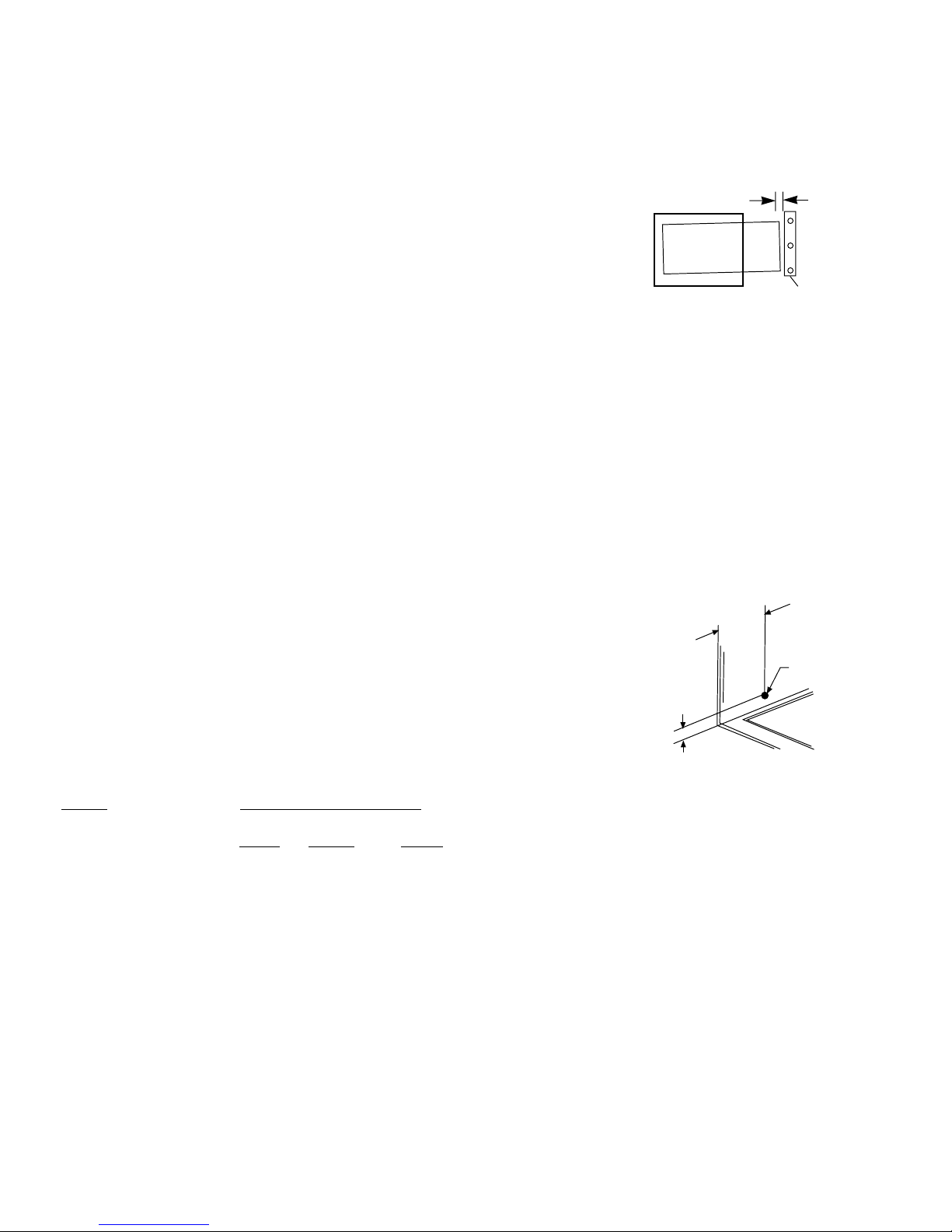
CAUTION
:When installation is complete, replacement
unit
MUSThave a rearward
slope
as shown.
2.
Remove oldAir Conditioner from wall sleeve and
prepare
wall sleeve as follows:
— Clean interior (do not disturb seals).
— Wall sleeve must be securely fastened in wall before
installin
g Air Conditioner. Drive more nails or screws
through
sleeve, into wall, if needed.
— Repair paint if needed.
3.
If not existing, drill a 3/16" clearance hole for ground-
ing
screw through left side of wall sleeve, in a clear area
about
3 inches maximum (to suit) back from front edge
of
sleeve as shown below. Next attach ground wire inside
sleeve,
using grounding screw, nut washer pull loose
end
of ground wire out front of sleeve, and temporarily
bend
it down and around lower edge of sleeve.
Wall sleeve to unit
sleeve
grounding
4.
Prepare the wall sleeve for installation of the new unit
per
the following Brand instructions.
#1
Emerson 15"Deep
#2
Fedders 19
3
⁄4"Deep
#3
Fedders or Friedrich 16
3
⁄4"Deep
#4
General Electric/Hotpoint 16
7
⁄8"Deep
#5
Sears or Carrier (51S Series) 18
5
⁄8"Deep
#6
Whirlpool 17
1
⁄8"Deep
#7
Whirlpool 23"Deep
#8
White-Westinghouse/Frigidaire/ 16"+ 17
1
⁄2"Deep
Carrier
(52F Series)
#9
White-Westinghouse/Frigidaire 22"Deep
5.
Install new unit into wall sleeve.
6. To attach ground wire to the new unit, remove the
screw
from the left side front.
7. Assemble and install the
Trim Frame (see instruction).
P/N 66121624
REAR
UNIT
FRONT
LEVEL
1/4”
to 5/16”
Wa ll
Sl ee ve
3"
Max.
3
/
16
"
Hole
1"
Grille Aluminum 1
Nuts
(plastic) 4
Screw
w/washer 4
1
Installation Instructions
14,000 BTU TTW
Page 2
This units increased performance characteristics meant;
1. The rear air intake moved to the opposite side.
2. The depth had to be increased.
It is very important that these installation instructions are followed so your unit can operate at maximum
efficiency.
If this is an existing sleeve, and there is an existing rear grille, the louvers will have to be bent as per the
instructions at the beginning of each section.
If this proves too difficult to accomplish;
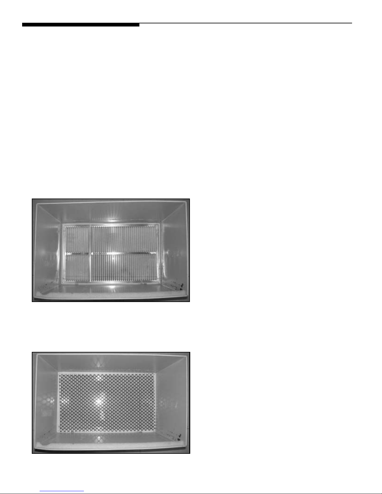
EITHER
1. Remove the existing grille.
2. Place the included aluminum grille towards the rear of the unit.
3. Mark through the hole positions.
4. Drill through the sleeves flanges with a 1/8” drill bit.
5. Attached the new grille with self-threading screws and washers (not included).
6. It is VERY IMPORTANT that the partition be placed on the left side of the sleeve as shown below.
OR
1. Remove the existing grille.
2. Use Plastic grille and secure to sleeves flanges using existing screws and washers.
2
Page 3

Wall Sleeve Brands:
Rear Louvers
60
°
7"
60°
Top View
#1 Emerson 15"Deep
1. Redirect the louvers at the back of the wall sleeve as shown
opposite. The use of pliers is recommended.
2. Attach (1) 1 ½” x 3/8” x 25” long seal in the center at the
top of the sleeve. Remove the backing paper and press
into position.
3. Attach (2) 1 ½” x 3/8” x 14” seals to the left and right sides
of the sleeve.
4. Cut the 1 ½” x 3/8” x 25” long seal to 14” long and attach
it to the vertical section of the rear grille as shown.
5. Attach (2) 4 ½” x 3 ½” x 1 ½” centering/support blocks
one on each side wall. Place in center of side wall with
the tapered end facing the opening.
6. Gently slide unit into sleeve.
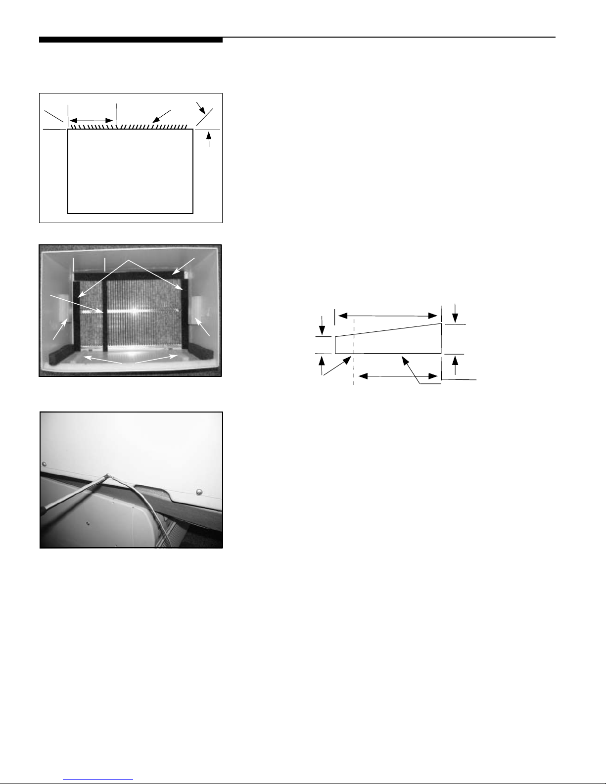
7. Before sliding all-the-way back, remove 2nd screw from
front on left side of unit.
8. Remove the plastic washer from the screw.
9. Screw and attach the other end of the ground wire to
the unit as shown in picture. Make sure that the toothed
washer is against the cabinet.
10. Slide the unit completely to the rear to ensure a good
seal, making sure the ground wire does not become
tangled.
11. Seal & Frame the unit as described on the last page of
these instructions.
3
←←
7"
→→
3
5
4
2
Page 4
Wall Sleeve Brands:
Rear Louvers
60
°
7"
60°
Top View
#2 Fedders 19 ¾" Deep
1. Redirect the louvers at the back of the wall sleeve as shown
opposite. The use of pliers is recommended.
2. Attach (2) 4 ½” x 3 ½” x 1 ½” centering/support blocks one
on each side wall. Place in center of side wall with the
tapered end facing the opening.
3. Cut (2) 17” Tapered Spacer Blocks as shown below into
two pieces.
4. The 4” section is placed in front of the rib on base with the
tapered end facing the back of the sleeve. The remaining
portion will be placed behind the rib again sloping toward
the rear of the sleeve. This helps induce a rearward slope
on the unit.
5. Attach (1) 1 ½” x 3/8” x 25” long seal in the center at the
top of the sleeve. Remove the backing paper and press
into position.
6. Attach (2) 1 ½” x 3/8” x 14” seals to the left and right sides
of the sleeve.
7. Cut the 1 ½” x 3/8” x 25” long seal to 14” long and attach it
to the vertical section of the rear grille as shown.
8. Gently slide unit into sleeve.
9. Before sliding all-the-way back, remove 2nd screw from
front on left side of unit.
10. Remove the plastic washer from the screw.
11. Screw and attach the other end of the ground wire to
the unit as shown in picture. Make sure that the toothed
washer is against the cabinet.
12. Slide the unit completely to the rear to ensure a good seal,
making sure the ground wire does not become tangled.
13. Seal & Frame the unit as described on the last page of
these instructions.
4
←←
7"
→→
6
3
7
5
.
Cut Here
3/4"
17"
4"
1"
Pr
otection Paper Backing
Tapered Spacer Block
2
2
Page 5

Wall Sleeve Brands:
Rear Louvers
60
°
7"
60°
Top View
#3 Fedders or Friedrich 16 ¾" Deep
1. Redirect the louvers at the back of the wall sleeve as shown
opposite. The use of pliers is recommended.
2. Attach (2) 4 ½” x 3 ½” x 1 ½” centering/support blocks one on
each side wall. Place in center of side wall with the tapered
end facing the opening.
3. Cut (2) 17” Tapered Spacer Blocks as shown below into three
pieces.
4. The 2 ½” section is placed in front of the rib on base with the
tapered end facing the back of the sleeve. Cut the remaining
portion to 12 ½” and place behind the rib again sloping toward
the rear of the sleeve. This helps induce a rearward slope on
the unit.
5. Attach (1) 1 ½” x 3/8” x 25” long seal in the center at the
top of the sleeve. Remove the backing paper and press
into position.
6. Attach (2) 1 ½” x 3/8” x 14” seals to the left and right sides
of the sleeve.
7. Cut the 1 ½” x 3/8” x 25” long seal to 14” long and attach it
to the vertical section of the rear grille as shown.
8. Gently slide unit into sleeve.
9. Before sliding all-the-way back, remove 2nd screw from front
on left side of unit.
10. Remove the plastic washer from the screw.
11. Screw and attach the other end of the ground wire to the
unit as shown in picture. Make sure that the toothed washer
is against the cabinet.
12. Slide the unit completely to the rear to ensure a good seal,
making sure the ground wire does not become tangled.
13. Seal & Frame the unit as described on the last page of
these instructions.
5
←←
7"
→→
6
3
7
5
2
2
Cut Here
3/4"
17"
1"
Pro
tection Paper Backing
Tapered Spacer Block
12-1/2"12-1/2"
2-1/2"
Page 6

Wall Sleeve Brands:
Rear Louvers
60
°
7"
60°
Top View
#4 General Electra/Hotpoint 16 7/8" Deep
1. Redirect the louvers at the back of the wall sleeve as shown
opposite. The use of pliers is recommended.
2. Cut (2) 17” Tapered Spacer Blocks as shown below into two
pieces.
3. Install as shown with the tapered end ½” from the back of the
sleeve. This helps induce a rearward slope on the unit.
4. Attach (1) 1 ½” x 3/8” x 25” long seal in the center at the top
of the sleeve. Remove the backing paper and press into
position.
5. Attach (2) 1 ½” x 3/8” x 14” seals to the left and right sides
of the sleeve.
6. Cut the 1 ½” x 3/8” x 25” long seal to 14” long and attach it
to the vertical section of the rear grille as shown.
7. Center unit & gently slide unit into sleeve.
8. Before sliding all-the-way back, remove 2nd screw from front
on left side of unit.
9. Remove the plastic washer from the screw.
10. Screw and attach the other end of the ground wire to the
unit as shown in picture. Make sure that the toothed washer
is against the cabinet.
11. Slide the unit completely to the rear to ensure a good seal,
making sure the ground wire does not become tangled.
12. Seal & Frame the unit as described on the last page of
these instructions.
6
←←
7"
→→
5
2
6
4
Cut Here
3/4"
17"
13"
1"
Pr
otection Paper Backing
Tapered Spacer Block
Page 7

←←
7"
→→
4
2
5
3
Wall Sleeve Brands:
Rear Louvers
60
°
7"
60°
Top View
#5 Sears or Carrier 51S Series 18 5/8" Deep
1. Redirect the louvers at the back of the wall sleeve as shown
opposite. The use of pliers is recommended.
2. Install (2) tapered spacer blocks to the floor of the sleeve as
shown. DO NOT CUT THESE BLOCKS. This helps induce
a rearward slope on the unit.
3. Install as shown with the tapered end ½” from the back of the
sleeve. This helps induce a rearward slope on the unit.
4. Attach (1) 1 ½” x 3/8” x 25” long seal in the center at the top
of the sleeve. Remove the backing paper and press into
position.
5. Attach (2) 1 ½” x 3/8” x 14” seals to the left and right sides
of the sleeve.
6. Cut the 1 ½” x 3/8” x 25” long seal to 14” long and attach it
to the vertical section of the rear grille as shown.
7. Center unit & gently slide unit into sleeve.
8. Before sliding all-the-way back, remove 2nd screw from front
on left side of unit.
9. Remove the plastic washer from the screw.
10. Screw and attach the other end of the ground wire to the
unit as shown in picture. Make sure that the toothed washer
is against the cabinet.
11. Slide the unit completely to the rear to ensure a good seal,
making sure the ground wire does not become tangled.
12. Seal & Frame the unit as described on the last page of
these instructions.
7
Page 8

←←
7"
→→
5
2
6
4
Wall Sleeve Brands:
Rear Louvers
60
°
7"
60°
Top View
#6 Whirlpool 17 1/8" Deep
1. Redirect the louvers at the back of the wall sleeve as shown
opposite. The use of pliers is recommended.
2. Cut (2) 17” Tapered Spacer Blocks as shown below into
two pieces.
3. Install to the floor of the sleeve as shown. This helps
induce a rearward slope on the unit.
4. Attach (1) 1 ½” x 3/8” x 25” long seal in the center at the
top of the sleeve. Remove the backing paper and press
into position.
5. Attach (2) 1 ½” x 3/8” x 14” seals to the left and right
sides of the sleeve.
6. Cut the 1 ½” x 3/8” x 25” long seal to 14” long and attach it
to the vertical section of the rear grille as shown.
7. Center unit & gently slide unit into sleeve.
8. Before sliding all-the-way back, remove 2nd screw from front
on left side of unit.
9. Remove the plastic washer from the screw.
10. Screw and attach the other end of the ground wire to the
unit as shown in picture. Make sure that the toothed washer
is against the cabinet.
11. Slide the unit completely to the rear to ensure a good seal,
making sure the ground wire does not become tangled.
12. Seal & Frame the unit as described on the last page of
these instructions.
8
Cut Here
3/4"
17"
13"
1"
Pr
otection Paper Backing
Tapered Spacer Block
Page 9

Wall Sleeve Brands:
Rear Louvers
60
°
7"
60°
Top View
#7 Whirlpool 23" Deep
1. Redirect the louvers at the back of the wall sleeve as shown
opposite. The use of pliers is recommended.
Because of the increased unit depth, first try dry fitting
using the method described below:
1. Place (2) 1 ½” x 1 ½” x 14” seals against each side.
2. Gently slide unit in and check if amount extending from the
sleeve is sufficient once the trim frame is attached.
3. If position is okay, remove unit and Proceed to the next step.
If not go to step 8.
4. Attach (1) 1 ½” x 1 ½” x 25” long seal in the center at the
top of the sleeve. Remove the backing paper and press into
position.
5. Attach (2) 1 ½” x 1 ½” x 14” seals to the left and right sides
of the sleeve.
6. Cut the 1 ½” x 1 ½” x 25” long seal to 14” long and attach it
vertically to the rear grill 7” from the left side.
7. Attach the tapered spacer blocks to the floor of the sleeve.
Now go to step 13.
Use these next steps if the unit requires extra extension
into the room.
8. Attach 1” x ¾” x 14” long seal over the solid vertical portion
of the rear grille.
9. Attach (2) 4 ½” x 3 ½” x 1 ½” foam blocks with the slot
overlapping the seal above.
10. Install the divider into the slots of the foam blocks. You may
need to trim the length to size.
11. Cut the 1 ½” x 1 ½” x 25” seal to fit the top of the sleeve.
The pieces must be fitted flush to the edge of the divider.
12. Attach (2) 1 ½” x 1 ½” x 14” seals along the sides of the
sleeve again making sure all seals are flush.
13. Center unit & gently slide unit into sleeve.
14. Before sliding all-the-way back, remove 1st screw from
front on left side of unit.
15. Remove the plastic washer from the screw.
16. Screw and attach the other end of the ground wire to the
unit as shown in picture. Make sure that the toothed washer
is against the cabinet.
17. Slide the unit completely to the rear to ensure a good seal,
making sure the ground wire does not become tangled.
18. Seal & Frame the unit as described on the last page of
these instructions.
9
8
9
11
12
←←
7"
→→
5
6
4
Page 10

Wall Sleeve Brands:
#8 White Westinghouse/Frigidaire/
Carrier 52F Series
16" + 17 ½" Deep
1. If the wall sleeve does not have a rear grille or louvered
panel, install the plastic grille from the kit. The plastic
grille is mounted to the inside of the wall sleeve at the rear
flanges. There are (4) plastic nuts in the flanges of the wall
sleeve. If some are missing replacements are included in
the accessory kit, and can be simply pressed into the square
holes in the flanges. Place the grille against the rear flanges
and use the (4) large washers and screws to secure the grille.
7"
→→
←←
3
2
3
of the sleeve. Remove the backing paper and press into
position.
3. Attach (2) 1 ½” x 3/8” x 14” seals to the left and right sides
of the sleeve.
4. Attach 1” x ¾” 14” long seal vertically 7” from the left side
of the sleeve.
2. Attach (1) 1 ½” x 3/8” x 25” long seal in the center at the top
4
5. Center unit & gently slide unit into sleeve.
6. Before sliding all-the-way back, remove 2nd screw from front
on left side of unit.
7. Remove the plastic washer from the screw.
8. Screw and attach the other end of the ground wire to the
unit as shown in picture. Make sure that the toothed washer
is against the cabinet.
9. Slide the unit completely to the rear to ensure a good seal,
making sure the ground wire does not become tangled.
10. Seal & Frame the unit as described on the last page of
these instructions.
10
Page 11

Wall Sleeve Brands:
←←
7"
→→
7
6
5
#9 White Westinghouse or Frigidaire 22" Deep
1. If the wall sleeve does not have a rear grille or louvered
panel, install the plastic grille from the kit. The plastic
grille is mounted to the inside of the wall sleeve at the rear
flanges. There are (4) plastic nuts in the flanges of the wall
sleeve. If some are missing replacements are included in
the accessory kit, and can be simply pressed into the square
holes in the flanges. Place the grille against the rear flanges
and use the (4) large washers and screws to secure the grille.
Because of the increased unit depth, first try dry fitting
using the method described below:
2. Place (2) 1 ½” x 1 ½” x 14” seals against each side.
3. Gently slide unit in and check if amount extending from the
sleeve is sufficient once the trim frame is attached.
4. If position is okay, remove unit and Proceed to the next step.
If not go to step 8.
6
5. Attach (1) 1 ½” x 1 ½” x 25” long seal in the center at the
top of the sleeve. Remove the backing paper and press into
position.
6. Attach (2) 1 ½” x 1 ½” x 14” seals to the left and right sides
of the sleeve.
7. Cut the 1 ½” x 1 ½” x 25” long seal to 14” long and attach it
vertically to the rear grill 7” from the left side.
Use the next steps if the unit requires extra extension into
the room.
8. Attach 1” x ¾” 14” long seal over the solid vertical portion of
8
11
the rear grille.
9. Attach (2) 4 ½” x 3 ½” x 1 ½” foam blocks with the slot
overlapping the seal above.
10. Install the divider into the slots of the foam blocks. You may
9
need to trim the length to size.
11. Cut to fit the 1 ½” x 1 ½” x 25” seal to fit the top of the sleeve.
The pieces must be fitted flush to the edge of the divider.
12
12. Attach (2) 1 ½” x 1 ½” x 14” seals along the sides of the
sleeve again making sure all seals are flush.
13. Center unit & gently slide unit into sleeve.
14. Before sliding all-the-way back, remove 1st screw from front
on left side of unit.
15. Remove the plastic washer from the screw.
16. Screw and attach the other end of the ground wire to the
unit as shown in picture. Make sure that the toothed washer
is against the cabinet.
17. Slide the unit completely to the rear to ensure a good seal,
making sure the ground wire does not become tangled.
18. Seal & Frame the unit as described on the last page of
these instructions.
11
Page 12

FINISHING INSTALLATION:
1. Install the 1” x 1 ½” x 84” long stuffer-seal between the
wall-sleeve and the unit. A flat-bladed screwdriver or putty
knife is recommended.
2. Assemble the trim frame by inserting top and bottom
peieces into side pieces and snapping into place.
3. Pull cord through trim frame then slide over unit until flush
with wall.
12
 Loading...