

Page 1
BEER COOLER
6.1 CU FT
170 L
TABLE OF CONTENTS
Important Safety Instructions.....................1
Unpacking and Setup................................4
Features at a Glance.................................5
Assembly and Installation..........................6
Door Removal Instructions........................12
Temperature Controls................................13
USER MANUAL
EFRB200,EFRB200C
Helpful Hints.................................................14
Energy Saving Tips.......................................15
Vacation and Moving Tips.............................15
Normal Operating Sounds and Sights..........15
Care and Cleaning........................................16
Before You Call.............................................17
Page 2
IMPORTANT SAFETY INSTRUCTIONS
WARNING:
Please read all instructions before using this unit.
FOR YOUR SAFETY
• DO NOT store or use gasoline, or other flammable liquids in the vicinity of this or any other
appliance. Read product labels for warnings regarding flammability and other hazards.
• DO NOT operate the appliance in the presence of explosive fumes.
• Remove all staples from the carton. Staples can cause severe cuts, and also destroy finishes
if they come in contact with other appliances or furniture.
DEFINITIONS
This is the safety alert symbol. It is used to alert you to potential personal injury hazards. Obey
all safety messages that follow this symbol to avoid possible injury or death.
DANGER indicates an imminently hazardous situation which, if not
avoided, will result in death or serious minjury.
WARNING indicates a potentially hazardous situation which, if not
avoided, could result in death or serious injury.
CAUTION indicates a potentially hazardous situation which, if not
avoided, may result in minor or moderate injury.
IMPORTANT indicates installation, operation or maintenance information
which is important but not hazard-related.
INSTALLATION CHECKLIST
Doors
Door seals completely to cabinet on all sides
Door is level across the top
Leveling
Unit is level, side-to-side and tilted 1/4” (6 mm)
front-to-back
Cabinet is setting solid on all corners
Electrical Power
House power turned on
Appliance plugged in
Final Checks
Shipping material removed
Appliance temperatures set
Registration card sent in
CHILD SAFETY
Destroy or recycle the carton, plastic bags, and any exterior wrapping material immediately after
the appliance is unpacked. Children should NEVER use these items to play. Cartons covered
with rugs, bedspreads, plastic sheets or stretch wrap may become airtight chambers, and can
quickly cause suffocation.
1
Page 3

PROPER DISPOSAL OF YOUR APPLIANCE
RISK OF CHILD ENTRAPMENT
Child entrapment and suffocation are not problems of the past. Junked or abandoned
appliances are still dangerous – even if they will sit for “just a few days.” If you are getting rid of
your old appliance, please follow the instructions below to help prevent accidents.
PROPER DISPOSAL OF APPLIANCE
We strongly encourage responsible appliance recycling/disposal methods. Check with your
utility company or visit www.energystar.gov/recycle for more information on recycling your old
appliance.
BEFORE YOU THROW AWAY YOUR OLD APPLIANCE:
• Remove doors.
• Leave shelves in place so children may
not easily climb inside.
• Have refrigerant removed by a qualified
service technician.
WARNING These guidelines must be followed to ensure that safety
mechanisms in this unit will operate properly.
ELECTRICAL INFORMATION
• The appliance must be plugged into its own dedicated 115 Volt, 60 Hz., AC only electrical
outlet. The power cord of the appliance is equipped with a three-prong grounding plug for
your protection against electrical shock hazards. It must be plugged directly into a properly
grounded three prong receptacle. The receptacle must be installed in accordance with local
codes and ordinances. Consult a qualified electrician. Avoid connecting keg cooler to a Ground
Fault Interruptor (GFI) circuit. Do not use an extension cord or adapter plug.
• If the power cord is damaged, it should be replaced by an authorized service technician to
prevent any risk.
• Never unplug the appliance by pulling on the power cord. Always grip the plug firmly, and pull
straight out from the receptacle to prevent damaging the power cord.
• Unplug the appliance before cleaning and before replacing a light bulb to avoid electrical shock.
• Performance may be affected if the voltage varies by 10% or more. Operating the appliance
with insufficient power can damage the compressor. Such damage is not covered under your
warranty.
• Do not plug the unit into an electrical outlet controlled by a wall switch or pull cord to prevent
the unit from being turned off accidentally.
IMPORTANT Turning the Temperature Control to
“OFF” turns off the compressor and prevents your
appliance from cooling, but does not disconnect the
power to the other electrical components. To turn off
power to your appliance you must unplug the power
cord from the electrical outlet.
2
Page 4

WARNING
CO2 CANISTER SAFE HANDLING
• CO
canisters must be handled with extreme care. They contain potentially
2
hazardous high pressure compressed gas. Make sure you read and understand all of
these instructions before installation.
• Never attempt to refill a CO2 cylinder yourself. They can be refilled at locations such
as welding supply shops, party stores, fire supply shops, or where kegs are purchased.
• ALWAYS connect CO2 gas canisters to a pressure regulator.
• NEVER drop or throw the CO2 canister.
• NEVER connect gas canister directly to keg.
• ALWAYS keep CO2 canisters in a cool place (21.5°C(70°F) or less) and away from heat.
• In case of CO2 leakage, ventilate and evacuate the area immediately.
• ALWAYS keep canister secured in an upright position.
• Check the Department of Transportation (D.O.T.) test date on the canister neck and do
not use if older than five (5) years.
• Return outdated canister to your gas supplier for one that is within the time limit.
3
Page 5
UNPACKING AND SETUP
This Use and Care Manual provides specific assembly, operating and maintenance instructions
for your model. Use the keg cooler only as instructed in this Use and Care Manual. Before
starting the keg cooler, follow these important first steps.
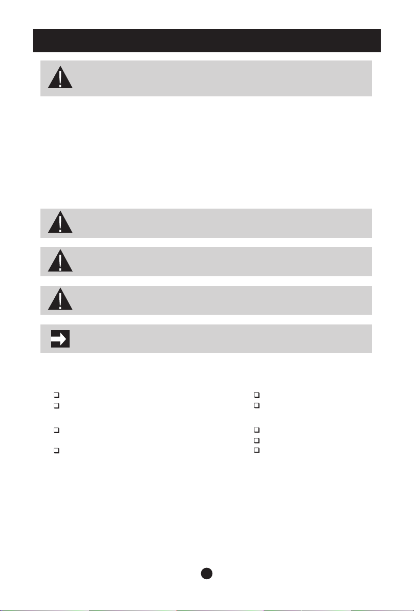
PARTS
Your keg cooler comes with several small boxes that contain all the required parts and
accessories. Check to make sure that you have received all of the components listed below.
BEVERAGE DELIVERY KIT BOX
(1) Drip Tray
(2) Casters and Washers
(3) Retaining Strap
(4) Hole Plug
(5) Faucet Knob
(6) CO2 Regulator (with plastic washer)
(7) Keg Coupler
(8) Small Hose (Gas Line)
(9) Rubber Gasket (Black)
(For bottom of Dispensing Tower)
(10) Guard Rail
(11) Dispenser Tower (with faucet)
(12) CO2 Canister (Empty)
(13) Bag of spare parts
(replacement seals and washers)
1 piece
4 pieces
1 piece
1 piece
1 piece
1 piece
1 piece
1 piece
1 piece
1 piece
1 piece
1 piece
1 bag
Drip Tray
Faucet Knob
Rubber Gasket
Dispenser
Tower
1
Casters and
Washers
5
C0 Regulator
2
9
11 12
C0 Canister
2
2
6
Retaining Strap
Keg Coupler
Spare Parts
3
Hole Plug
7
Small Hose
11
Guard Rail
13
NOTE
The box comes with a “D System” type Keg Coupler (7). Depending on your choice of beer,
you may require a different Keg Coupler (7). Check with your local beer distributor to
determine which type of system you need, and order additional Keg Couplers as needed.
4
8
10
4
Page 6
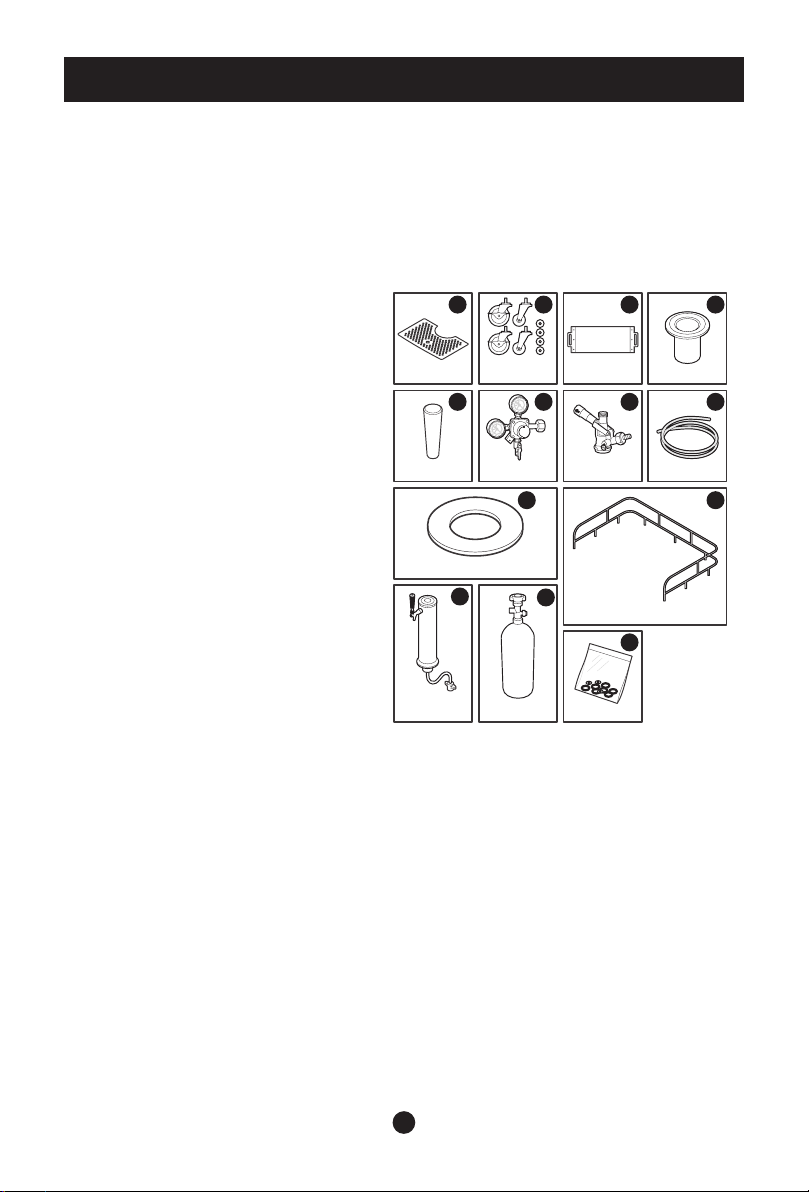
FEATURES AT A GLANCE
Faucet Handle
Features may vary according to model
Dispensing Tower
Drip Tray
Casters (x4)
Faucet
Top Rail
Temperature Control
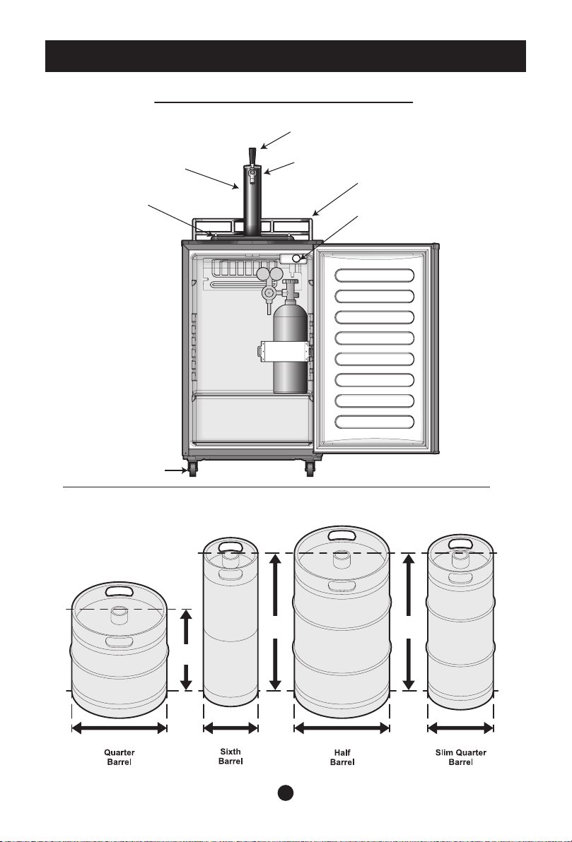
Standard Keg Sizes for this Cooler
59.4 cm
(23-3/8 in.)
35.2 cm
(13-7/8 in.)
41.0 cm (16-1/8 in.) 41.0 cm (16-1/8 in.)
23.5 cm (9-1/4 in.)
5
59.4 cm
(23-3/8 in.)
28.3 cm (11-1/8 in.)
Page 7
ASSEMBLY AND INSTALLATION
This Use and Care Guide provides specific operating instructions for your model. Use this unit
only as instructed in this Use and Care Guide. Before starting the unit, follow these important
first steps.
LOCATION
• Choose a place that is near a grounded electrical outlet. Do not use an extension cord or an
adapter plug.
• If possible, place the unit out of direct sunlight and away from the range, dishwasher or other
heat sources.
• For optimum performance, this product should only be used indoors under normal ambient
conditions.
• The appliance must be installed on a floor that is level and strong enough to support a fully
loaded unit.
• If the appliance has been placed in a horizontal or tilted position for any period of time, please
wait at least 24 hours before plugging the unit in.
INSTALLING THE CASTERS
Follow the steps below to install the casters.
1. Empty the inside of the cabinet completely and lay the Keg Cooler down on its side.
We recommend that you place a piece of cardboard or cloth underneath the cabinet to prevent
dents or scratches.
2. Insert the casters into the holes on the bottom corners of the cabinet. Tighten each caster by
turning the head of the bolts clockwise with a wrench (not provided in the kit).
3. Once all four casters have been tightened, stand the cabinet in its upright position.
NOTE: Two of the casters include locking mechanisms to ensure the unit does not
slide on hard floors. These two locking casters should be fastened at the front end
of the unit, with the unlocked casters fastened on the rear end.
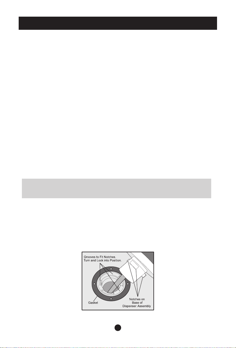
INSTALLING THE BEER TAP
There are notches on the bottom of the dispensing tower that line up with grooves inside the
opening on the top of the Keg Cooler. Align the dispensing tower with the opening on the top of
the unit, then place inside and twist clockwise until secure. Use four screws to fasten the beer tap.
Pay attention to use the thin black gasket (9) for assembly (see illustration). If you find this to be
a tight fit, apply some soapy water to the gasket to make the tower easier to twist into place.
Also see illustration showing hose connections to CO2 regulator to the beer tap.
6
Page 8

INSTALLING THE GUARDRAIL
Follow the steps below to install the guardrail.
1. Place the guard rail on top of the cabinet.
2. Align all support feet of the guardrail with the holes on the top of the unit and press down into
place.
CAUTION: Do not install the unit where the temperature will drop below 13°C
(55°F) or rise above 32°C (90°F). The compressor will not be able to maintain
proper temperatures inside the unit.
INSTALLATION
Installation clearances
• Allow the following clearances for ease of installation, proper air circulation, and electrical
connections:
Sides and Top 12.7 cm (5 inches)
Back 12.7 cm (5 inches)
NOTE: If your unit is placed with the door hinge side against a wall, you may have
to allow additional space so the door can be opened wider.
LEVELING
All four casters of your unit must rest firmly on a solid floor. Use adjustable wrench to adjust
leveling screws.
CAUTION: do not attempt to move or relocate the keg cooler with a keg inside.
REGULATOR INSTALLATION
• Check to ensure plastic washer is inside the hex nut.
• Fasten the CO2 regulator (6) to the CO2 canister (12). Place
the regulator to the right of the tank.
• Tighten the hex nut securely. DO NOT over tighten. Over-
tightening may damage the gasket in the nut of the regulator.
SMALL CO2 HOSE TO REGULATOR CONNECTION
• Attach wing nut on end of small hose (8) to fitting at bottom of regulator (6).
7
Page 9
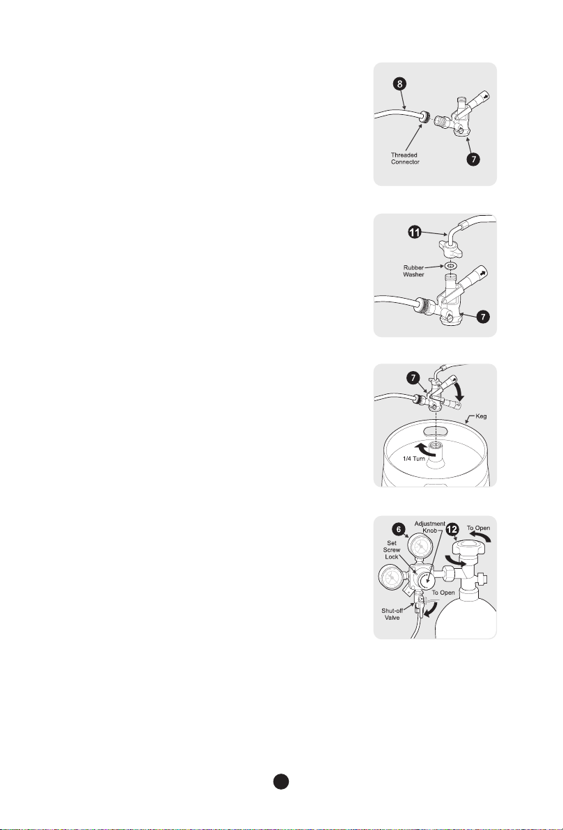
SMALL CO2 HOSE TO COUPLER CONNECTION
• Secure other end of small hose (8) to the threaded
end of keg coupler (7) as shown. Be sure to fully
tighten fitting.
NOTE: Depending on your choice of beer, you may require a
different keg coupler (7). Check with your local beer
distributor to determine which type of system you need, and
order additional keg couplers as needed.
CLEAR HOSE TO COUPLER CONNECTION
Place one of the supplied rubber washers inside
the wing nut on the one end of the clear hose
(beverage delivery line) and attach to keg coupler
(7). Be sure to tighten the nut securely to prevent
leakage. DO NOT overtighten. Overtightening may
damage the gasket in the nut.
COUPLER TO KEG INSTALLATION
• Align locks on keg coupler (7) with housing on
top of keg and push down on the keg coupler (7).
Make sure top handle is in the up position.
• Turn the tap head handle clockwise 1/4 turn. The
tap head is now secured to the keg.
• Pull the tap handle out and push down until it locks
into place to open the port in the keg.
DELIVERY HOSE PRESSURIZATION
• Open the CO2 canister valve all the way by turning
counterclockwise until it stops. This valve seals
at both the fully open and fully closed positions.
Failure to completely open or close the valve could
result in premature loss of CO2 pressure.
• Open the regulator shut-off valve by moving it to
the 6 o’clock position.
• Check gauge pressure. Adjust the regulator
adjustment knob Knob as necessary until the pressure
reads between 12 to 14 psi. You may first need to
loosen set screw located behind knob. After setting
regulator to correct pressure, set screw may be retightened
to lock knob in place.
8
Page 10
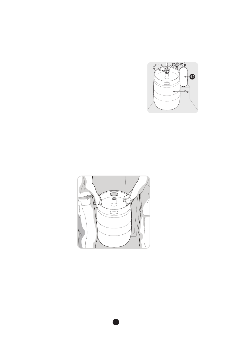
CO2 CANISTER TO CABINET INSTALLATION
• Lift and place the CO2 canister (12) with the CO2 regulator (6) on the shelf at rear right hand
corner of cabinet. It is important that the canister be kept in an upright position to operate
efficiently. Hook one end of retaining strap (3) over metal bracket at rear, then stretch around
canister and hook other end over front bracket.
KEG TO CABINET INSTALLATION
• Place the keg on the support shelf and push
back next to the CO2 canister (12) (See TIPS ON
INSTALLING KEG TO THE CABINET) inside the
cabinet as shown.
WARNING
SAFE KEG HANDLING
• Installing the keg to the cabinet is a two-person team effort. NEVER lift a full keg alone.
Doing so may cause severe injury.
• With the door fully open and the help of another person, lift the keg vertically on both
sides until the keg is higher than the keg support shelf.
• Set the edge of the keg on top of the plastic protective plate located on top of keg
support shelf. Slide the keg back until it is fully inside the cabinet.
• Care must be taken to avoid damage to the temperature control and shelf tower located
in the cabinet.
NOTE: The above illustration does not show the tap installed for clarity of installation.
9
Page 11
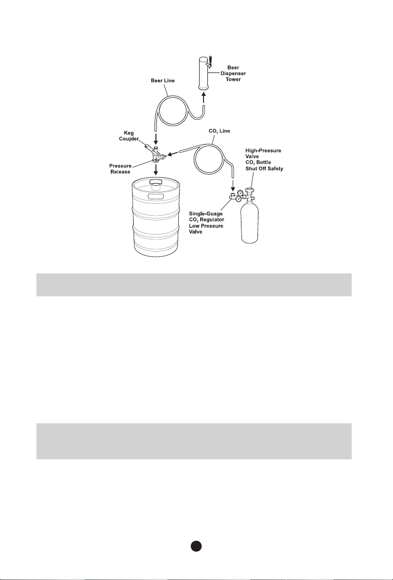
DELIVERY HOSE ARRANGEMENT
NOTE: Failure to route hoses properly may cause the hose to become kinked or
caught in door.
OPERATING YOUR KEG COOLER
• Make sure that the keg cooler is plugged in properly to a 115V, 60Hz AC only electrical outlet.
• Make sure that the drip tray and sump are secured under the faucet.
• Start with a clean beverage glass that has been wetted in cold water. Place the glass at a 45º
angle, 2.5 cm (1 in.) below the faucet. Do not let the glass touch the faucet. Open the faucet
all the way.
• After the glass has reached half full, gradually bring the glass to an upright position.
• Let the remaining beverage run straight down the middle. This insures proper release of CO
by producing a 1.9 to 2.5 cm (3/4 to 1 in.) foam head.
• Close the faucet completely and quickly.
2
NOTE: It is normal to see condensation forming around the faucet. This
condensation is caused by the temperature difference between the cold beverage
and the inner surfaces of the faucet when beverage is being drawn through the line.
10
Page 12

HOW TO REPLACE AN EMPTY CO2 CANISTER
• Remove hoses from routing clips.
• Remove the keg, then remove CO2 canister.
• Close the canister valve of the empty canister by turning clockwise until it stops.
• Close the regulator shut-off valve by moving it to the 9 o’clock position.
• Carefully remove regulator from the empty CO2 canister by loosening the nut with an
adjustable wrench. Check the condition of the gasket inside the nut and replace if necessary.
• Return canister to your local carbonic gas source for filling. (We suggest looking in your yellow
pages under “Carbonic Gas.” Sources of CO2 vary from community to community but it is often
available at welding supply stores and beverage distributors.)
• Remove dust cap from new canister nut, if any.
• With the canister valve still in closed position, reattach the regulator to the new canister using
an adjustable wrench. Ensure the plastic washer is inside of the nut. Tighten nut until it feels
snug but be careful not to overtighten as you will damage the gasket inside the stem nut.
• Check to make sure that the braided gas line hose is still securely attached to the regulator.
• Open the canister valve all the way by turning counter-clockwise until it stops. This valve seals
at both the fully open and fully closed positions. Failure to completely open or close the valve
could result in premature loss of CO2 pressure.
• Open the regulator shut-off valve by moving it down to the 6 o’clock position.
• Check gauge pressure. Adjust the regulator adjustment screw as necessary until the pressure
reads between 12 to 14 psi. Tighten the adjustment lock nut.
• Replace keg and route hose clips.
11
Page 13

DOOR REMOVAL INSTRUCTIONS
NOTE: The direction in which your unit door opens (door swing) can be reversed,
from left to right or right to left, by moving the door hinges from one side to the
other. Reversing the door swing should be performed by a qualified person.
IMPORTANT: Before you begin, turn the unit temperature control to “OFF” and
remove the electrical power cord from the wall outlet. Remove any food from door
shelves.
DOOR REMOVAL AND REVERSAL INSTRUCTIONS:
1 Remove dispensing tower from unit.
2 Remove three (3) screws at rear edge of top cover, then lift up at rear and slide forward to
remove cover (see Figure A).
3 Remove two (2) screws from top door hinge and lift up out of door bushing (see Figure B).
6 Re-install door with LH bushing placed over hinge pin.
7 Re-install top hinge on opposite corner of cabinet and then assemble top cover in reverse
order of Step 2.
12
Page 14

TEMPERATURE CONTROLS
COOL DOWN PERIOD
For proper operation, allow the unit to operate with the door closed for at least 12 hours before
placing the keg inside.
KEG COOLER CONTROLS
Temperature control
This rotary control is the primary control for the refrigerated compartment temperature. If the
unit is too warm, adjust this control in the “Max” direction. If the unit is too cold, adjust this
control in the “Min” direction.
TEMPERATURE SETTING AND ADJUSTMENT
For beer storage, the recommended initial setting is “Med.” Under most conditions,
this setting will provide for dispensed beer between 1-3 ºC (34-38 ºF) You may adjust as
required to suit your individual taste and the keg cooler operating conditions. After a control
adjustment, always allow 24 hours for the beer to stabilize at the new temperature before
making additional adjustments.
IMPORTANT: Turning the unit temperature control to “OFF” turns off the
compressor, but does not disconnect the power to the light bulb and other electrical
components. To turn off power to your unit, you must unplug the power cord from
the wall outlet.
NOTE: When purchasing a beer keg, always purchase a keg cold ( <3 ºC (38 ºF)),
transport as quickly as possible, and get it installed in the cold unit within two (2)
hours. Under most conditions, these guidelines will allow serving of properly
cooled beerwithin 24 hours. Purchasing a keg at a temperature above 3 ºC (38 ºF),
and/or exposure to elevated temperatures longer than two (2) hours will require
additional time for the beer to be cooled to optimum serving temperature.
13
Page 15

HELPFUL HINTS
PARTS OF A CO2 REGULATOR
(A) Low Pressure Gauge
(B) Adjustment Knob
(C) Adjustment Lock Set Screw
(D) Shut-off Valve
(E) CO2 Nut (used to connect to CO2 canister)
(F) High Pressure Gauge
BEER STORAGE TEMPERATURE
• Draft beer is not pasteurized, so it must be kept cold, preferably at 3 ºC (38 ºF). Temperatures
above 3 ºC (38 ºF) may cause the beer to become wild, turn sour and cloudy.
RECOMMENDED KEG HANDLING
• Be sure the keg is cold when you purchase it.
• Transfer keg from place of purchase and install in keg cooler in two (2) hours or less.
• After the keg is installed in the keg cooler, allow 24 hours for beverage to reach recommended
temperature.
• If the keg is exposed to ambient temperatures longer than two (2) hours, additional cooling
time will be required before beverage will reach recommended temperature.
TYPICAL BEER SERVING EQUIVALENTS
¼ Keg ½ Keg
Grams/Ounces 28123g/992
56245g/1984
Litres/Gallons
29 L / 7.75 gal
58 L / 15.5 gal.
Cases (355 mL
(12 oz.) bottles)
Weight (full)
CAUTION: DO NOT attempt to move or relocate this keg cooler with a keg inside.
3 3/8 (82 bottles)
37 kg / 82.5 lb. 75 kg / 165 lb
14
6 3/4 (165 bottles)
Page 16

ENERGY SAVING TIPS
• Install the keg cooler in the coolest part of the room, out of direct
sunlight and away from heating ducts or registers. Do not place the keg
cooler next to heat-producing appliances such as a range, oven, or
dishwasher.
• Do not overcrowd the keg cooler or block cold air vents. Doing so
causes the keg cooler to run longer and use more energy.
• Organize the keg cooler to reduce door openings. Remove as many
items as needed at one time and close the door as soon as possible.
VACATION AND MOVING TIPS
Vacation and Moving Tips
Short Vacations
Long Vacations • Remove all food and ice if you will be gone one month or more.
Moving • NEVER MOVE KEG COOLER WITH KEG INSIDE.
• Leave keg cooler operating during vacations of three (3) weeks or less.
• Use all perishable items from keg cooler compartment.
• Turn controls to the OFF position and disconnect power.
• Clean interior thoroughly.
• Leave door open to prevent odours and mould build-up. Block door open if necessary.
• If using handcart, load from side.
• Adjust leveling legs all the way up to protect
• Pad cabinet to avoid scratching surface.
surface during sliding or moving.
NORMAL OPERATING SOUNDS AND SIGHTS
UNDERSTANDING THE SOUNDS YOU MAY HEAR
Your new, high-efficiency keg cooler may introduce unfamiliar sounds. These sounds normally
indicate your keg cooler is operating correctly. Some surfaces on floors, walls, and kitchen
cabinets may make these sounds more noticeable.
NOTE: Rigid foam insulation is very energy efficient, but is not a sound insulator.
Following is a list of major components in your keg cooler and the sounds they can cause:
Evaporator Refrigerant through the evaporator may create a boiling or gurgling sound.
Electronic control and automatic defrost control These parts can produce a snapping or
clicking sound when turning the cooling system on and off.
Compressor Modern, high-efficiency compressors run much faster than in the past. The
compressor may have a high-pitched hum or pulsating sound.
Drain pan (not removable) You may hear water dripping into the drain pan during the defrost
cycle.
15
Page 17

CARE and CLEANING
PROTECTING YOUR INVESTMENT
Keeping your keg cooler clean maintains appearance and prevents odour build-up. Wipe up any
spills immediately and clean the keg cooler at least twice a year. When cleaning, take the
following precautions:
• Never use CHLORIDE or cleaners with bleach to clean stainless steel.
• Do not wash any removable parts in a dishwasher.
• Always unplug the electrical power cord from the wall outlet before cleaning.
• Remove adhesive labels by hand. Do not use razor blades or other sharp instruments which
can scratch the appliance surface.
• Do not remove the serial plate.
Do not use abrasive cleaners such as window sprays, scouring cleansers, brushes, flammable
fluids, cleaning waxes, concentrated detergents, bleaches or cleansers containing petroleum
products on plastic parts, interior doors, gaskets or cabinet liners. Do not use paper towels,
metallic scouring pads, or other abrasive cleaning materials or strong alkaline solutions.
NOTE: If you set your temperature controls to turn off cooling, power to lights and
other electrical components will continue until you unplug the power cord from the
wall outlet.
CAUTION: 1.Pull the keg cooler straight out to move it. Shifting it from side to side
may damage flooring. Be careful not to move the keg cooler beyond the plumbing
connections. 2.Damp objects stick to cold metal surfaces. Do not touch refrigerated
surfaces with wet or damp hands.
IMPORTANT: If you store or move your keg cooler in freezing temperatures, be sure
to completely drain the water supply system. Failure to do so could result in water
leaks when the keg cooler is put back into service. Contact a service representative
to perform this operation.
Part What To Use Tips and Precautions
Interior and Door
Liners
Door Gaskets • Soap and water Wipe gaskets with a clean soft cloth.
Drawers and Bins • Soap and water Use a soft cloth to clean drawer runners and tracks.
Exterior and
Handles
Exterior and
Handles
(Stainless Steel
Models Only)
• Soap and water
• Baking soda and water
• Soap and water
• Non-abrasive glass cleaner
• Soap and water
• Stainless steel cleaners
Use 30 mL (2 tbsp) of baking soda in 945 mL (1 qt.) of warm water. Be sure
to wring excess water out of sponge or cloth before cleaning around
controls, light bulb or any electrical part.
Do not use commercial household cleaners containing ammonia, bleach or
alcohol to clean handles. Use a soft cloth to clean smooth handles. DO
NOT use a dry cloth to clean smooth doors.
Never use CHLORIDE or cleaners with bleach to clean stainless steel.
Clean stainless steel front and handles with non-abrasive soapy water and
a dishcloth. Rinse with clean water and a soft cloth. Use a non-abrasive
stainless steel cleaner. These cleaners can be purchased at most home
improvement or major department stores. Always follow manufacturer’s
instructions. Do not use household cleaners containing ammonia or bleach.
NOTE: Always clean, wipe and dry with the grain to prevent
scratching. Wash the rest of the cabinet with warm water and mild liquid
detergent. Rinse well, and wipe dry with a clean soft cloth.
16
Care and Cleaning Tips
Page 18

BEFORE YOU CALL
CONCERN POTENTIAL CAUSE COMMON SOLUTION
RUNNING OF KEG COOLER
Keg cooler does not
run.
Keg cooler runs too
much or too long.
Interior keg cooler tem perature is too cold.
Interior keg cooler
temperature is too
warm.
Keg cooler external
surface temperature is
warm.
WATER/MOISTURE/FROST INSIDE KEG COOLER
Moisture collects on
inside of keg cooler
walls.
WATER/MOISTURE/FROST OUTSIDE KEG COOLER
Moisture collects on
outside of keg cooler
walls.
ODOUR IN KEG COOLER
Unpleasant odours. • Interior needs to be cleaned. • Clean interior with sponge, warm water, and baking soda.
DOOR PROBLEMS
Door will not close. • Keg cooler is not level. • This condition can force the cabinet out of square and
• Keg cooler is plugged into a
circuit that has a ground fault
interrupt.
• Temperature control is in the
“O” position.
• Keg cooler may not be plugged
in, or plug may be loose.
• House fuse blown or tripped
circuit breaker.
• Power outage.
• Room or outside weather is
hot.
• Keg cooler has recently been
disconnected for a period of time.
• Doors are opened too frequently
or too long.
• Keg cooler door may be slightly
open.
• Temperature control is set too
low.
• Keg cooler gasket is dirty, worn,
cracked, or poorly
• Temperature control is set too
low.
• Temperature control is set too
warm.
• Door is kept open too long or is
opened too frequently.
• Door may not be seating properly.
• Keg cooler has recently been
disconnected for a period of time.
• The external walls can be as
much as -1
than room temperature.
• Weather is hot and humid.
• Door may not be seating
properly.
• Door is kept open too long or
opened too frequently.
• Door may not be seating
properly, causing the cold air
from inside the keg cooler to
meet warm moist air from the
outside.
fitted.
O
C (30 OF) warmer
• Use another circuit. If you are unsure about the outlet,
have it checked by a technician.
• See SETTING THE TEMPERATURE CONTROL section.
• Ensure plug is tightly pushed into outlet.
• Check/replace fuse with a 15 amp time-delay fuse. Reset
circuit breaker.
• Check house lights. Call local electric company.
• It’s normal for the keg cooler to work longer under these
conditions.
• It takes four (4) hours for the keg cooler to cool down
completely.
• Warm air entering the keg cooler causes it to run more.
Open door less often.
• See DOOR PROBLEMS section.
• Adjust temperature control to warmer setting. Allow
several hours for temperature to stabilize.
• Clean or change gasket. Leaks in door seal will cause keg
cooler to run longer in order to maintain desired temperatures.
• Adjust temperature control to a warmer setting. Allow
several hours for temperature to stabilize.
• Adjust temperature control to a colder setting. Allow
several hours for the temperature to stabilize.
• Warm air enters the keg cooler every time the door is
opened. Open the door less often.
• See DOOR PROBLEMS section.
• It takes four (4) hours for the keg cooler to cool down
completely.
• This is normal while the compressor works to transfer heat
from inside the keg cooler.
• This is normal.
• See DOOR PROBLEMS section.
• Open the door less often.
• See DOOR PROBLEMS section.
misalign the door. Level the unit .
certified
17
Page 19

CONCERN POTENTIAL CAUSE COMMON SOLUTION
SOUND AND NOISE
Louder sound levels
whenever keg cooler
is on.
Longer sound levels
when compressor
comes on.
Popping or cracking
sound when compressor comes on.
Bubbling or gurgling
sound like water boil ing.
Vibrating or rattling
noise.
Snapping noise. • Temperature control turning keg
COMMON DRAFT PROBLEMS
WILD BEER - Beer,
when drawn, is all
foam, or too much
foam and not enough
liquid beer.
FLAT BEER - Foamy
head disappears
quickly; beer lacks
usual zestful brewery
fresh flavour.
CLOUDY BEER - When
beer in glass appears
hazy, not clear.
• Modern keg coolers have in-
creased storage capacity and
more stable temperatures. They
require a high-efficiency compres-
sor.
• Keg cooler operates at high
pressure during the start of the
cycle.
“ON”
• Metal parts undergo expansion
and contraction, as in hot water
pipes.
• Refrigerant (used to cool keg
cooler) is circulating throughout
the system.
• Keg cooler is touching the wall. • Move keg cooler slightly away from the wall.
cooler on and off.
• Beer drawn improperly.
• Creeping regulator.
• Applied pressure is set too high.
• Hot spots in line.
• Tapped into a warm keg (should
be 1.1
°C-3.5°C(34°F-38°F)
• Centre malfunctioning.
• Faucet is in bad, dirty or worn
condition.
• Dirty glasses.
• Applied pressure is set too low.
• CO
is cut off.
2
• Beer too cold.
• Loose tap or vent connections.
• Sluggish regulator.
• Frozen or near frozen beer.
• Unrefrigerated beer for long periods
of time.
• Dirty glasses.
• Dirty faucet.
• Unrefrigerated foods placed on top
of cold keg.
• This is normal. When the surrounding noise level is low, you
might hear the compressor running while it cools the interior.
• This is normal. Sound will level off or disappear as the keg
cooler continues to run.
• This is normal. Sound will level off or disappear as the keg
cooler continues to run.
• This is normal.
• This is normal.
• Make sure faucet is opened all the way. Close quickly when
done.
• Replace with a new regulator.
• Readjust regulator to a lower pressure until foam subsides.
When pressure is properly set, you should be able to pour 10
oz. of beer in (5)five seconds.
• Make sure beer del
the interior of the keg cooler.
• Wait until keg cools down to proper temperature.
• Have keg cooler serviced to return it to proper operating
condition.
• Thoroughly clean faucet with recommended cleaning kit.
Replace all worn seals.
• Wash glasses using soap-free detergent.
• Increase pressure until beer at a rate of 2 oz. per
second.
• Do not turn off CO
ready to be removed.
• Increase temperature of keg cooler. See SETTING THE
TEMPERATURE CONTROL section.
• Check that coupler is properly installed in keg.
• Replace regulator.
• Return keg to place of purchase and exchange for one that
has been properly refrigerated.
• Exchange keg for fresh one.
• Wash glasses using soap-free detergent.
• Clean faucet with recommended cleaning kit.
• Remove items from atop k
erator.
ivery line is not pinched and is fully inside
flows
supply line to keg until keg is empty and
2
eg and place in a separate refrig-
18
Page 20

DANGER – Risk Of Fire Or Explosion. Flammable Refrigerant
Used. To Be Repaired Only By Trained Service Personnel.
Do Not Puncture Refrigerant Tubing
CAUTION – Risk Of Fire Or Explosion. Flammable Refrigerant
Used. Consult Repair Manual/Owner’s Guide Before Attempting
To Service This Product. All Safety Precautions Must be Followed
CAUTION – Risk Of Fire Or Explosion. Dispose Of Property In
Accordance With Federal Or Local Regulations. Flammable
Refrigerant Used
CAUTION – Risk Of Fire Or Explosion Due To Puncture Of
Refrigerant Tubing; Follow Handling Instructions Carefully.
Flammable Refrigerant Used
19
Page 21

Baril à bière
6.1 CU FT
170 L
TABLE DES MATIÈRES
Consignes de sécurité importantes............1
Déballage et montage................................4
Aperçu des caractéristiques.......................5
Assemblage et installation..........................6
Instructions pour le retrait des portes........12
Commandes de température.....................13
Conseils utiles............................................14
Manuel de l'utilisateur
EFRB200,EFRB200C
Conseils pour économiser l'énergie...................15
Conseils pour les vacances et les
déménagements................................................15
Bruits et éléments visuels d'un
fonctionnement normal......................................15
Entretien et nettoyage.......................................16
Avant de faire appel au service après-vente.....17
Page 22

CONSIGNES DE SÉCURITÉ IMPORTANTES
AVERTISSEMENT : veuillez lire ces instructions au complet
avant d'utiliser l'appareil.
POUR VOTRE SÉCURITÉ
• N'entreposez PAS et n'utilisez pas d'essence ou tout autre liquide inflammable à proximité de cet
appareil ou de tout autre électroménager. Lisez les étiquettes d'avertissement du produit concernant
l'inflammabilité et les autres dangers.
• Ne faites PAS fonctionner l'appareil en présence de vapeurs explosives.
• Enlevez toutes les agrafes du carton. Les agrafes peuvent causer de graves coupures et
endommager les finis si elles entrent en contact avec d'autres appareils électroménagers ou meubles.
DÉFINITIONS
Voici le symbole d'alerte de sécurité. Il sert à vous mettre en garde contre les risques potentiels de
blessures corporelles. Respectez toutes les consignes de sécurité qui suivent ce symbole afin d'éviter
les blessures ou la mort.
La mention DANGER indique un danger imminent qui causera la mort ou des
blessures graves s'il n'est pas évité.
La mention AVERTISSEMENT indique une situation potentiellement dangereuse
qui, si elle n'est pas évitée, peut entraîner des blessures graves, voire la mort.
La mention ATTENTION signale la présence d'une situation
potentiellement dangereuse qui, si elle n'est pas évitée, est susceptible de
causer des blessures mineures ou moyennement graves.
La mention IMPORTANT indique des renseignements importants relatifs à
l'installation, au fonctionnement ou à l'entretien. Toutefois, ceux-ci n'impliquent
aucune notion de danger.
LISTE DE VÉRIFICATION POUR L'INSTALLATION
Portes
La porte se ferme hermétiquement sur la caisse
de tous les côtés
La porte est à niveau sur toute sa partie
supérieure
Mise à niveau
L'appareil est à niveau d'un côté à l'autre et
incliné de 6 mm (1/4 po) de l'avant vers l'arrière
Les quatre coins de la caisse reposent
fermement sur le plancher
Alimentation en électricité
Le système électrique de la maison
est sous tension
L'appareil est branché
Vérifications finales
Le matériel d'expédition a été enlevé
Les températures de l'appareil sont réglées
La carte d'enregistrement a été postée
SÉCURITÉ DES ENFANTS
Détruisez ou recyclez le carton, les sacs en plastique et tout autre matériau d'emballage externe
immédiatement après avoir déballé l'appareil. Les enfants ne devraient JAMAIS jouer avec ces articles.
Les boîtes de carton recouvertes de tapis, de couvre-lits, de feuilles de plastique ou de pellicule étirable
peuvent se transformer en chambres hermétiques et rapidement provoquer une suffocation.
1
Page 23

MISE AU REBUT APPROPRIÉE DE VOTRE APPAREIL ÉLECTROMÉNAGER
RISQUES D'ENFERMEMENT DES ENFANTS
Les dangers d'enfermement et de suffocation des enfants constituent un problème dont il faut
sérieusement tenir compte. Les appareils électroménagers abandonnés ou mis au rebut sont
dangereux, même si ce n'est « que pour quelques jours ». Si vous désirez vous défaire de votre
vieil appareil électroménager, veuillez suivre les instructions ci-dessous afin d'aider à prévenir
les accidents.
MISE AU REBUT APPROPRIÉE DE L'APPAREIL ÉLECTROMÉNAGER
Nous encourageons fortement les méthodes responsables de recyclage et de mise au rebut des
appareils électroménagers. Vérifiez auprès de votre entreprise de services publics ou visitez le site
www.energystar.gov/recycle pour de plus amples renseignements sur comment recycler votre vieil
appareil électroménager.
AVANT DE METTRE VOTRE VIEIL APPAREIL
ÉLECTROMÉNAGER AU REBUT :
• Enlevez les portes.
• Laissez les clayettes en place pour que les enfants ne puissent pas
grimper facilement à l'intérieur.
• Faites retirer le fluide frigorigène par un technicien en entretien
et en réparation qualifié.
AVERTISSEMENT vous devez suivre ces instructions pour que les mécanismes de
sécurité de cet appareil fonctionnent correctement.
INFORMATION CONCERNANT L'ÉLECTRICITÉ
• L'appareil doit être branché que dans sa propre prise électrique CA de 115 V et 60 Hz. Le cordon
d'alimentation de l'appareil est muni d'une fiche à trois broches avec mise à la terre pour vous
protéger contre les chocs électriques. Cette fiche doit être branchée directement dans une prise à
trois branches avec mise à la terre. La prise murale doit être installée conformément aux codes et
règlements locaux. Consultez un électricien qualifié. Évitez de brancher le refroidisseur de baril à
bière à un circuit muni d'un disjoncteur de fuite à la terre (GFI). N'utilisez pas de rallonge électrique
ou d'adaptateur.
• Si le cordon d'alimentation est endommagé, il doit être remplacé par un technicien en entretien et
réparation autorisé afin d'éviter tout accident.
• Ne débranchez jamais l'appareil en tirant sur le cordon d'alimentation. Tenez toujours la fiche
fermement en la tirant en ligne droite pour la retirer de la prise afin d'éviter d'endommager le cordon.
• Pour éviter les chocs électriques, débranchez l'appareil avant de le nettoyer ou de remplacer une
ampoule.
• Une tension variant de 10 % ou plus risque de nuire au rendement de l'appareil. Le fait de faire
fonctionner l'appareil avec une alimentation insuffisante peut endommager le compresseur. Un
tel dommage n'est pas couvert par votre garantie.
• Ne branchez pas l'appareil dans une prise commandée par un interrupteur mural ou un cordon de
tirage pour éviter que l'appareil ne soit accidentellement mis hors tension.
IMPORTANT Le fait de tourner la commande à la position
« OFF » met le compresseur hors fonction et
désactive les fonctions de refroidissement, mais ne coupe
pas l'alimentation des autres composants électriques. Pour
couper l'alimentation de votre appareil, vous devez débrancher
le cordon d'alimentation de la prise murale.
2
Page 24

AVERTISSEMENT
MANIPULATION SÉCURITAIRE DU CONTENANT DE CO
2
• Les contenants de CO2 doivent être manipulés avec beaucoup de prudence. Ils contiennent
un gaz comprimé haute pression potentiellement dangereux. Assurez-vous de lire et
comprendre ces instructions avant de procéder à l'installation.
• Ne jamais recharger une bouteille de CO
dans des endroits comme des magasins de matériel de soudure, d'accessoires de fêtes,
vous-même. Vous pouvez les faire recharger
2
de matériel de prévention des incendies ou là où l'on vend des barils à bière.
• TOUJOURS raccorder les contenants de CO
• Ne JAMAIS laisser tomber ou lancer le contenant de CO
• Ne JAMAIS raccorder un contenant de gaz directement au baril à bière.
• TOUJOURS entreposer les contenants de CO
les tenir loin des sources de chaleur.
• Si une fuite de CO
• TOUJOURS vous assurer que le contenant est en position verticale et qu'il ne peut tomber.
survient, bien aérer et évacuer la zone immédiatement.
2
à un régulateur de pression.
2
dans un endroit frais (21ºC/70º F ou moins) et
2
.
2
• Vérifiez la date du test du ministère des Transports sur le goulot du contenant et ne l'utilisez
pas si elle date de plus de cinq (5) ans.
• Retournez les contenants périmés à votre détaillant de produits gazeux pour vous en procurer
respectant les délais prescrits.
3
Page 25

DÉBALLAGE ET MONTAGE
Ce manuel d'utilisation et d'entretien contient des instructions d'assemblage, d'utilisation et d'entretien
spécifiques à votre modèle. N'utilisez le refroidisseur de baril à bière que conformément aux
instructions présentées dans ce Guide d'utilisation et d'entretien. Avant de mettre le refroidisseur de
baril à bière en marche, suivez ces premières étapes importantes.
PIÈCES
Votre refroidisseur de baril à bière est livré avec plusieurs petites boîtes contenant toutes les pièces
et accessoires requis. Assurez-vous d'avoir reçu tous les composants énumérés ci-dessous.
BOÎTE DE LA TROUSSE DE
DISTRIBUTION DE BOISSON
(1) Plateau d'égouttement
(2) Roulettes et rondelles
(3) Courroie de retenue
(4) Bouchon cache-trou
(5) Poignée du robinet
(6) Régulateur de CO
de plastique)
(7) Coupleur du baril
(8) Petit tuyau (conduite du gaz)
(9) Joint d'étanchéité en caoutchouc (noir)
(Pour le bas de la tour distributrice)
(10) Barre de retenue
(11) Tour distributrice (avec robinet)
(12) Contenant de CO
(13) Sac de pièces de rechange
(joints et rondelles de rechange)
(avec rondelle
2
(vide)
2
1 pièce
4 pièce
1 pièce
1 pièce
1 pièce
1 pièce
1 pièce
1 pièce
1 pièce
1 pièce
1 pièce
1 pièce
1 sac
REMARQUE
Dans la boîte se trouve un coupleur de baril de type « Système D » (7). Selon votre choix de
bière, vous pourriez avoir besoin d'un autre type de coupleur de baril (7). Vérifiez auprès de
votre distributeur de bière le type de système le plus approprié à vos besoins et, au besoin,
commandez des coupleurs de barils additionnels.
4
Page 26

APERÇU DES CARACTÉRISTIQUES
59,4 cm
(23-3/8 po)
35,2 cm
(13-7/8 po)
41,0 cm (16-1/8 po) 41,0 cm (16-1/8 po)
23,5 cm (9-1/4 po)
5
59,4 cm
(23-3/8 po)
28,3 cm (11-1/8 po)
Page 27

ASSEMBLAGE ET INSTALLATION
Ce guide d'utilisation et d'entretien contient des instructions d'utilisation propres à votre modèle.
N'utilisez cet appareil que conformément aux instructions présentées dans ce Guide d'utilisation et
d'entretien. Avant de mettre l'appareil en marche, suivez ces premières étapes importantes.
EMPLACEMENT
• Choisissez un emplacement près d'une prise électrique avec mise à la terre. N'utilisez pas de
rallonge électrique ou de fiche d'adaptation.
• Si possible, placez l'appareil à l'abri de la lumière directe du soleil, et loin de la cuisinière, du
lavevaisselle et de toute autre source de chaleur.
• Pour un rendement optimal, cet appareil ne doit être utilisé qu'à l'intérieur dans des conditions
ambiantes normales.
• L'appareil doit être installé sur un plancher qui est à niveau et assez solide pour le supporter
adéquatement quand il est rempli à pleine capacité.
• Si l’appareil a été mis en position horizontale ou inclinée pour une période de temps, quelle qu'elle
soit, veuillez attendre au moins 24 heures avant de le brancher.
INSTALLATION DES ROULETTES
Suivez les étapes ci-dessous pour installer les roulettes.
1. Videz entièrement l'intérieur de la caisse et couchez le refroidisseur de baril à bière sur le côté.
Nous vous recommandons de mettre un morceau de carton ou de tissu sous la caisse pour éviter
d'endommager ou de rayer la surface.
2. Insérez les roulettes dans les trous situés aux coins inférieurs de la caisse. Serrez chacune des
roulettes en tournant la tête des boulons vers la droite à l'aide d'une clé à molette (n'est pas fournie
dans la trousse de l'appareil).
3. Une fois les quatre roulettes fixées solidement, mettez la caisse en position verticale.
REMARQUE : deux des roulettes comprennent un mécanisme de blocage pour garantir que
l'appareil ne glisse pas sur les planchers dont les surfaces sont dures. Ces deux roulettes à
blocage doivent être fixées sur le bord avant de l'appareil, les deux autres sur le bord arrière.
INSTALLATION DU ROBINET À BIÈRE
Des encoches au bas de la tour distributrice s'alignent avec des rainures dans l'ouverture sur le dessus
du refroidisseur de baril à bière. Alignez la tour distributrice avec l'ouverture sur le dessus de l'appareil,
puis placez-la à l'intérieur et tournez vers la droite jusqu'à ce qu'elle soit bien fixée. Utilisez quatre vis
pour fixer le robinet de bière. Assurez-vous d'utiliser le mince joint d'étanchéité noir (9) lors de
l'assemblage (voir l'illustration). Si vous trouvez qu'il est difficile de le faire faute d'espace, mettez un
peu d'eau savonneuse
6
Page 28

INSTALLATION DE LA BARRE DE RETENUE
Suivez les étapes ci-dessous pour installer la barre de retenue.
1. Placez la barre de retenue sur le dessus de la caisse.
2. Alignez tous les supports de la barre de retenue avec les trous sur le dessus de l'appareil et
appuyez pour les insérez à leur place.
ATTENTION : n'installez pas l'appareil à un endroit où la température pourrait descendre en
dessous de 13 °C (55 °F) ou s'élever à plus de 32 °C (90 °F). Le compresseur ne pourrait pas
maintenir des températures appropriées à l'intérieur de l'appareil.
INSTALLATION
Dégagements pour l'installation
• Prévoyez les dégagements suivants pour une installation plus facile, une circulation d'airappropriée
et pour les raccordements électriques :
Côtés et dessus 13 cm (5 po)
Arrière 13 cm (5 po)
REMARQUE : si votre appareil est positionné contre un mur du côté des charnières, prévoir
plus d'espace pour permettre à la porte de s'ouvrir davantage.
MISE À NIVEAU
Les quatre roulettes de votre appareil doivent reposer fermement sur un plancher solide. Utilisez une
clé à molette pour régler la hauteur des vis de mise à niveau.
ATTENTION : n'essayez pas de déplacer ou de relocaliser le refroidisseur de baril à bière
quand il contient un baril à bière.
INSTALLATION DU RÉGULATEUR
• Assurez-vous que la rondelle de plastique est à l'intérieur de
Un écrou
hexagonal
l'écrou hexagonal.
• Fixez le régulateur de CO2 (6) au contenant de CO2 (12). Placez
le régulateur à la droite du réservoir.
• Serrez bien l'écrou hexagonal. Ne le serrez PAS trop fort. Le fait de
le serrer trop fort risquerait d'endommager le joint d'étanchéité
dans l'écrou du régulateur.
RACCORDEMENT DU PETIT TUYAU DE CO2 AU RÉGULATEUR
• Fixez l'écrou à oreilles de l'extrémité du petit tuyau (8) au raccord situé dans le bas du régulateur (6).
7
Page 29

RACCORDEMENT DU PETIT TUYAU DE CO2 AU
COUPLEUR
• Fixez l'autre bout du petit tuyau (8) à l'extrémité filetée du coupleur
du baril (7), tel qu'illustré. Assurez-vous de bien serrer le raccord.
REMARQUE : selon votre choix de bière, vous pourriez avoir besoin
d'un autre type de coupleur de baril (7). Vérifiez auprès de votre
distributeur de bière le type de système le plus approprié à vos
besoins et, au besoin, commandez des coupleurs de barils
additionnels.
RACCORDEMENT DU TUYAU TRANSPARENT AU
COUPLEUR
• Placez l'une des rondelles de caoutchouc fournies dans l'écrou à
oreilles de l'une des extrémités du tuyau transparent (8) (conduite
d'alimentation de la boisson) et fixez-le au coupleur du baril (7).
Assurez-vous de bien serrer l'écrou pour prévenir les fuites. Ne le
serrez PAS trop fort. Le fait de le serrer trop fort risquerait
d'endommager le joint d'étanchéité dans l'écrou.
INSTALLATION DU COUPLEUR AU BARIL
• Alignez les arrêts du coupleur du baril (7) avec l'embout sur le
dessus du baril et appuyez en poussant le coupleur du baril (7) vers
le bas. Assurez-vous que la poignée supérieure est en position levée.
• Faites pivoter la poignée du robinet vers la droite de 1/4 de tour. La
poignée du robinet est dorénavant fixée au baril.
• Tirez la poignée du robinet vers l'extérieur, puis poussez vers le bas
jusqu'à ce qu'elle s'enclenche à sa place en ouvrant l'orifice dans le
baril.
PRESSURISATION DU TUYAU D'ALIMENTATION
• Ouvrez la vanne du contenant de CO2 en la tournant vers la gauche
jusqu'au bout. Cette vanne est scellée quand elle est entièrement
ouverte ou entièrement fermée. Le fait de ne pas l'ouvrir ou de ne
pas la fermer entièrement pourrait provoquer une perte prématurée
de pression du CO2.
• Ouvrez le robinet d'arrêt du régulateur en le plaçant à la position
« 6 heures » (s'il s'agissait d'une horloge).
• Vérifier la pression sur l'indicateur de pression. Ajustez le bouton de
réglage du régulateur si nécessaire, jusqu'à ce que la pression se
situe entre 12 et 14 lb/po². Il est possible que vous ayez à desserrer la vis située derrière le bouton.
Une fois la pression ajustée correctement, vous pouvez resserrer la vis pour que le bouton de
commande soit verrouillé dans cette position.
8
Page 30

INSTALLATION DU CONTENANT DE CO2 À LA CAISSE
• Soulevez et placez le contenant de CO2 (12) auprès du régulateur de CO2 (6) sur la tablette située
dans le coin arrière droit de la caisse. Il est important de conserver le contenant en position verticale
pour qu'il fonctionne de manière efficace. Accrochez l'une des extrémités de la courroie de retenue (3)
au support en métal à l'arrière, puis étirez-la autour du baril en fixant l'autre bout au support avant.
INSTALLATION DU BARIL À LA CAISSE
• Placez le baril sur la clayette et poussez-le à côté du contenant
de CO2 (12) (voir les CONSEILS POUR L'INSTALLATION DU
BARIL À LA CAISSE) à l'intérieur de la caisse, tel qu'illustré.
CONSEILS POUR L'INSTALLATION DU BARIL À LA CAISSE
AVERTISSEMENT
MANIPULATION SÉCURITAIRE DU BARIL
• Pour installer un baril dans la caisse, il faut être deux. Ne soulevez JAMAIS un baril plein
seul. Vous pourriez vous blesser grièvement.
• En laissant la porte grande ouverte et avec l'aide d'une autre personne, soulevez le baril à la
verticale des deux côtés jusqu'à ce que le baril soit plus haut que la clayette qui le supportera.
• Placez le bord du baril sur le dessus du plateau de protection en plastique situé sur le dessus
de la clayette. Faites glisser le baril jusqu'au fond de la caisse.
• Il faut faire attention à ne pas endommager la commande de température et la tour de la
clayette dans la caisse.
REMARQUE: par souci de clarté, l'illustration ci-dessus ne montre pas le robinet installé.
9
Page 31

DISPOSITION DU TUYAU D'ALIMENTATION
Conduite
de bière
Tour
distributrice
de bière
Coupleur
du baril
Relâchement
de pression
Conduite de CO
Robinet basse
pression à
manomètre
du régulateur
de CO
2
2
Robinet haute
pression
fermeture de sécurité
pour bouteille de CO
2
ATTENTION : si les tuyaux ne sont pas correctement disposés, ils pourraient se tordre ou
rester coincés dans la porte.
FONCTIONNEMENT DE VOTRE REFROIDISSEUR DE BARIL À BIÈRE
• Assurez-vous que le refroidisseur de baril à bière est bien branché dans une prise électrique de
115 V, 60 Hz et 15 A, CA uniquement.
• Assurez-vous que le plateau d'égouttement et le puisard sont bien fixés sous le robinet.
• Commencez en utilisant un verre à boisson propre mouillé dans de l'eau froide. Placez le verre à un
angle de 45º, un pouce sous le robinet. Ne laissez pas le verre toucher le robinet. Ouvrez le
robinet entièrement.
• Une fois le verre à moitié rempli, ramenez peu à peu le verre en position verticale.
• Laissez le reste de la boisson couler directement au milieu du verre. Procéder ainsi permet de
garantir une distribution appropriée de CO2 en produisant de 1,9 à 2,5 cm (3/4 à 1 po)o de mousse
en surface.
• Fermez entièrement et rapidement le robinet.
REMARQUE : il est normal que de la condensation s'accumule autour du robinet. Cette
condensation est provoquée par les écarts de températures entre la boisson froide et les
parois intérieures du robinet quand la boisson circule dans la conduite.
10
Page 32

COMMENT REMPLACER UN CONTENANT DE CO2 VIDE
• Retirez les tuyaux des agrafes de cheminement.
• Retirez le baril, puis retirez le contenant de CO2.
• Fermez la vanne du contenant vide en la tournant vers la droite jusqu'au bout.
• Fermez le robinet d'arrêt du régulateur en le plaçant à la position « 9 heures » (s'il s'agissait d'une
horloge).
• Retirez avec précaution le régulateur du contenant de CO2 vide en desserrant l'écrou à l'aide d'une
clé à molette. Vérifiez la condition du joint d'étanchéité dans l'écrou et remplacez-le si nécessaire.
• Rapportez le contenant à votre détaillant de gaz carbonique local pour le faire recharger. (Nous vous
suggérons de chercher dans les pages jaunes sous la rubrique « Gaz carbonique ». Les fournisseurs
de CO2 varient d'un endroit à l'autre, on en retrouve toutefois souvent dans des magasins vendant
des articles de soudure ou chez les distributeurs de boissons.)
• Si nécessaire, retirez le capuchon antipoussière de l'écrou du nouveau contenant.
• Alors que le contenant est toujours fermé, refixez le régulateur au nouveau contenant à l'aide d'une
clé à molette. Assurez-vous que la rondelle de plastique est à l'intérieur de l'écrou. Serrez bien
l'écrou, mais faites attention à ne pas le serrer trop fort, car cela risquerait d'endommager le joint
d'étanchéité à l'intérieur de l'écrou de la tige.
• Assurez-vous que le tuyau tressé de la conduite de gaz est toujours solidement fixé au régulateur.
• Ouvrez entièrement la vanne du contenant en la tournant vers la gauche jusqu'au bout. Cette vanne
est scellée quand elle est entièrement ouverte ou entièrement fermée. Le fait de ne pas l'ouvrir ou
de ne pas la fermer entièrement pourrait provoquer une perte prématurée de pression du CO2.
• Ouvrez le robinet d'arrêt du régulateur en l'abaissant à la position « 6 heures » (s'il s'agissait
d'une horloge).
• Vérifier la pression sur l'indicateur de pression. Ajustez la vis de réglage du régulateur si nécessaire,
jusqu'à ce que la pression se situe entre 12 et 14 lb/po². Serrez l'écrou autofreiné d'ajustement.
• Remettez le baril et les agrafes de cheminement du tuyau.
11
Page 33

INSTRUCTIONS POUR LE RETRAIT DES PORTES
REMARQUE : il est possible d'inverser l'orientation de l'ouverture de la porte de votre appareil,
de gauche à droite ou de droite à gauche, en déplaçant les charnières d'un côté à l'autre.
L'inversion des portes doit être effectuée par une personne qualifiée.
IMPORTANT : avant de commencer, tournez la commande de température de l'appareil à «OFF»
et débranchez le cordon d'alimentation de la prise murale. Retirez tous les aliments des
tablettes de la porte.
DÉPOSE ET INVERSION DE LA PORTE :
1 Retirez la tour distributrice de l'appareil.
2 Retirez les trois (3) vis du bord arrière du revêtement supérieur, puis soulevez-le à l'arrière et
glissez-le vers l'avant pour l'enlever (voir la Figure A).
3 Retirez deux (2) vis de la charnière supérieure de la porte et soulevez la porte pour la retirer de la
bague (voir la Figure B).
4 Sortez la porte de la charnière en la tirant vers le haut.
5 Retirez la charnière inférieure du coin droit de la caisse et déplacez-la vers le côté opposé
(voir la Figure C).
6 Réinstallez la porte en alignant la bague du côté gauche avec la cheville de la charnière.
7 Réinstallez la charnière supérieure sur le côté opposé de la caisse et installez le revêtement
supérieur en suivant l'ordre inverse de l'étape 2.
12
Page 34

COMMANDES DE TEMPÉRATURE
PÉRIODE DE REFROIDISSEMENT
Pour un bon fonctionnement, laissez l'appareil fonctionner la porte close pendant au moins 12 heures
avant d'y mettre un baril à bière.
COMMANDES DU REFROIDISSEUR DE BARIL À BIÈRE
Commande de température
Ce bouton de commande rotatif est la commande principale de la température du compartiment
réfrigérateur. Si l'appareil est trop chaud, tournez cette commande vers la position « Max ». Si l'appareil
est trop froid, tournez cette commande vers la position « Min ».
RÉGLAGE ET AJUSTEMENT DE LA TEMPÉRATURE
Pour entreposer la bière, il est recommandé de régler au départ la température à cinq « Med ».
Dans la plupart des conditions, ce réglage permettra à la bière distribuée d'atteindre une température
entre 1 ºC et 3 ºC (34 ºF et 38 ºF). Vous pouvez régler la température en fonction de vos goûts
personnels et les conditions de fonctionnement du refroidisseur de baril à bière. Une fois la commande
ajustée, toujours attendre 24 heures pour permettre à la bière de se stabiliser à la nouvelle température
avant de faire d'autres ajustements.
IMPORTANT : le fait de tourner la commande de l'appareil à « OFF » met le compresseur hors
fonction, mais ne coupe pas l'alimentation de l'ampoule ni des autres composants électriques.
Pour couper l'alimentation de votre appareil, vous devez débrancher le cordon d'alimentation
de la prise murale..
REMARQUE : quand vous achetez un baril à bière, toujours l'acheter déjà froid (à moins de
3 ºC (38 ºF), le transporter le plus rapidement possible et l'installer dans l'appareil froid dans
les deux (2) heures suivantes. Dans la plupart des conditions, ces instructions permettront de
servir la bière à une température appropriée dans les 24 heures. Le fait d'acheter le baril à une
température supérieure à 3 ºC (38 ºF) ou de l'exposer à des températures élevées pendant plus
de deux (2) heures fera en sorte qu'il faudra plus de temps pour refroidir la bière à une
température optimale pour la consommation.
13
Page 35

CONSEILS UTILES
COMPOSANTS D'UN RÉGULATEUR DE CO
(A) Manomètre basse pression
(B) Bouton d'ajustement
(C) Vis de verrouillage pour ajustement
(D) Robinet d'arrêt
(E) Écrou du CO2 (utilisé pour raccorder le contenant de CO2)
(F) Manomètre haute pression
2
TEMPÉRATURE DE CONSERVATION DE LA BIÈRE
• La bière en baril à bière n'est pas pasteurisée, il faut donc la conserver au froid, de préférence à
3 ºC (38 ºF). Des températures de plus de 3 ºC (38 ºF) pourraient faire mousser la bière davantage,
la rendre aigre et trouble. (F) Manomètre haute pression
MANIPULATION RECOMMANDÉE DU BARIL
• Assurez-vous que le baril est froid quand vous l'achetez.
• Transférez le baril du lieu où vous l'avez acheté et installez-le dans le refroidisseur de baril à bière
dans les deux (2) heures suivantes ou moins.
• Une fois le baril installé dans le refroidisseur de baril à bière, attendez 24 heures afin de permettre à
la boisson d'atteindre la température recommandée.
• Si le baril est exposé à des températures ambiantes plus de deux (2) heures, il faudra le laisser se
refroidir plus longtemps pour atteindre la température recommandée. CONSEILS UTILES ATTENTION
N'essayez PAS de déplacer ou de relocaliser le refroidisseur de baril à bière quand il contient un baril
de bière. ÉQUIVALENCES HABITUELLES
ÉQUIVALENCES HABITUELLES DE QUANTITÉS DE BIÈRE
¼ de baril ½ baril
Onces 992
Litres/Gallons
Caisses (bouteilles de
355 mL (12 oz.))
29 L / 7,75 gal
3 3/8 (82 bouteilles)
1984
58 L / 15,5 gal
6 3/4 (165 bouteilles)
Poids (complet)
ATTENTION : n'essayez PAS de déplacer ou de relocaliser le refroidisseur de baril à bière
quand il contient un baril de bière.
37 kg / 82,5 lb 75 kg / 165 lb
14
Page 36

CONSEILS POUR ÉCONOMISER L'ÉNERGIE
• Installez le refroidisseur de baril à bière dans la partie la plus fraîche de la
pièce, à l'abri du soleil direct et loin des conduits d'air chaud ou des registres.
Ne placez pas le refroidisseur de baril à bière à côté d'appareils qui produisent
de la chaleur tels une cuisinière, un four ou un lave-vaisselle.
• Évitez de surcharger le refroidisseur de baril à bière ou de bloquer les évents
d'air froid. Ceci pourrait faire fonctionner le refroidisseur de baril à bière plus
longtemps et consommer plusd'énergie.
• Disposez les contenants dans le refroidisseur de baril à bière de façon à
limiter le nombre de fois où il faudra ouvrir la porte. Prévoyez de prendre
plusieurs articles à la fois et refermez immédiatement la porte.
CONSEILS POUR LES VACANCES ET LES DÉMÉNAGEMENTS
Vacances de courte
durée
Vacances plus
longues
Déménagement • NE JAMAIS DÉPLACER LE REFROIDISSEUR DE BARIL À BIÈRE QUAND IL
• Laissez le refroidisseur de baril à bière fonctionner pour des vacances de trois (3)
semaines ou moins.
• Ne laissez aucun aliment périssable dans le compartiment du refroidisseur de baril à bière.
• Si vous prévoyez être absent un mois ou plus, retirez tous les aliments et tous les glaçons.
• Tournez les commandes à la position OFF et débranchez le cordon d'alimentation.
• Nettoyez l'intérieur à fond.
• Laissez la porte ouverte pour empêcher l'accumulation d'odeurs et de moisissures.
Si nécessaire, bloquez la porte pour qu'elle reste ouverte.
CONTIENT UN BARIL À BIÈRE.
• Si vous utilisez un diable, chargez-le sur le côté.
•
le déménagement.
• Enveloppez la caisse pour éviter d'égratigner la surface.
BRUITS ET ÉLÉMENTS VISUELS D'UN FONCTIONNEMENT NORMAL
COMPRENDRE LES BRUITS QUE VOUS ENTENDEZ
Votre nouveau refroidisseur de baril à bière pourrait émettre des bruits qui ne vous sont pas familiers.
Ces bruits indiquent habituellement que votre refroidisseur de baril à bière fonctionne correctement.
Certaines surfaces, notamment le plancher, les murs et les armoires de cuisine, peuvent amplifier ces
bruits.
REMARQUE : l'isolant en mousse rigide est efficace pour conserver l’énergie, mais il n'est pas
destiné à servir d'isolant acoustique.
Voici la liste des principaux composants de votre refroidisseurde baril à bière et des sons qu'ils
peuvent émettre :
Évaporateur La circulation du fluide frigorigène dans l'évaporateur peut faire un bruit de
bouillonnement ou de gargouillement.
Commande électronique et commande de dégivrage automatique Ces pièces peuvent émettre un
déclic ou un cliquetis lorsque le système de refroidissement s'arrête ou se remet en marche.
Compresseur Les compresseurs modernes à haut rendement énergétique fonctionnent beaucoup plus
vite que les anciens compresseurs. Le compresseur peut émettre un ronronnement aigu ou des pulsations.
Plateau de dégivrage (inamovible) Vous pourriez entendre l'eau qui tombe dans le plateau de
dégivrage pendant le cycle de dégivrage.
Conseils pour les vacances et les déménagements
15
Page 37

ENTRETIEN ET NETTOYAGE
PROTÉGER VOTRE INVESTISSEMENT
Gardez votre refroidisseur de baril à bière propre pour préserver son apparence et empêcher
l'accumulation d'odeurs. Essuyez immédiatement tout renversement et nettoyez le refroidisseur de
baril à bière au moins deux fois par année. Lorsque vous effectuez ce nettoyage, prenez les
précautions suivantes :
• Ne jamais utiliser de CHLORURE ou de nettoyants avec agent de blanchiment pour nettoyer l'acier
inoxydable.
• Ne lavez aucune pièce amovible dans un lave-vaisselle.
• Vous devez toujours débrancher le cordon d’alimentation de la prise murale avant le nettoyage.
• Enlevez les étiquettes adhésives à la main. N'utilisez pas de lame de rasoir ou autre instrument
pointu pouvant égratigner
la surface de l'appareil.
• N'enlevez pas la plaque signalétique.
N'utilisez pas de nettoyant abrasif tel que du nettoyant pour les vitres, de la poudre à récurer, une brosse,
du liquide inflammable, de la cire nettoyante, du détersif concentré, un agent de blanchimentou du nettoyant
renfermant des produits à base de pétrole sur les pièces en plastique, les portes intérieures, les joints
ou les revêtements de la caisse. N'utilisez pas d'essuie-tout, de tampon à récurer métallique ou tout
autre matériau de nettoyage abrasif ou solution alcaline forte.
REMARQUE : si vous réglez la commande de température pour arrêter le système de
refroidissement, l'éclairage et les autres composants électriques continueront à fonctionner
jusqu'à ce que vous débranchiez le cordon d'alimentation de la prise murale..
ATTENTION : 1.Tirez le refroidisseur de baril à bière en ligne droite pour le déplacer. Le balancer
de gauche à droite pourrait endommager le plancher. Faites attention de ne pas déplacer le
refroidisseur de baril à bière au-delà de ce que permettent les raccordements de plomberie.
2 . Les objets humides collent aux surfaces de métal froides. Ne touchez pas aux surfaces
réfrigérées si vous avez les mains mouillées ou humides.
IMPORTANT : si vous entreposez ou déménagez votre refroidisseur de baril à bière dans des
températures sous le point de congélation, assurez-vous de vidanger complètement le système
d'alimentation en eau. Autrement, des fuites d'eau pourraient se produire lorsque vous
remettrez votre refroidisseur de baril à bière en marche. Adressez-vous à un représentant de
service après-vente pour faire effectuer cette opération.
Pièce Produits à utiliser Conseils et précautions
Intérieur et
revêtements de
porte
Joints de porte • Eau et savon Essuyez les joints avec un chiffon propre et doux.
Bacs et
compartiments
Extérieur et
poignées
Extérieur et
poignées
(modèles
en acier
inoxydable
seulement)
• Eau et savon
• Bicarbonate de soude et eau
• Eau et savon Utilisez un linge doux pour nettoyer les glissières et les rails des tiroirs.
• Eau et savon
• Nettoyant pour verre non
• Eau et savon
• Nettoyants pour acier
Conseils pour l'entretien et le nettoyage
Utilisez 30 mL (2 c. à table) de bicarbonate de soude dans 1 L (1 pinte)
d'eau chaude. Assurez-vous de bien essorer l'eau de l'éponge ou du
chiffon avant de nettoyer autour des commandes, de l'ampoule ou
de toute pièce électrique.
Pour nettoyer les poignées, n'utilisez pas de nettoyant ménager commercial
abrasif
inoxydable
à base d'ammoniaque, de javellisant ou d'alcool. Utilisez un linge doux
pour nettoyer les poignées. N'utilisez PAS de chiffon sec pour
nettoyer les portes lisses.
N'utilisez jamais de CHLORURE ni de nettoyant avec agent de
blanchiment pour
Nettoyez l'avant et les poignées en acier inoxydable avec de l'eau
savonneuse non abrasive et un linge à vaisselle. Rincez avec de l'eau
propre et un linge doux. Utilisez un nettoyant pour acier inoxydable
non abrasif. Ces nettoyants peuvent être achetés dans la plupart des
quincailleries et des grands magasins. Suivez toujours les directives du
fabricant. N'utilisez pas de nettoyant ménager à base d'ammoniaque ou
de d'agent de blanchiment.
REMARQUE : nettoyez, essuyez et asséchez toujours dans le sens
des stries pour éviter les égratignures. Lavez le reste de la caisse
avec de l'eau chaude et un détergent liquide doux. Rincez bien et essuyez
à sec avec un linge doux et propre.
16
nettoyer l'acier inoxydable.
Page 38

AVANT DE FAIRE APPEL AU SERVICE APRÈS-VENTE
PROBLÈME CAUSE POSSIBLE SOLUTION HABITUELLE
FONCTIONNEMENT DU REFROIDISSEUR DE BARIL À BIÈRE
Le refroidisseur de baril
à bière ne fonctionne
pas.
Le refroidisseur de
baril à bière fonctionne
trop souvent ou trop
longtemps.
La température
intérieure du
refroidisseur de baril à
bière est trop froide.
La température
intérieure du
refroidisseur de baril à
bière est trop chaude.
La température de la
surface externe du
refroidisseur de baril à
bière est élevée.
EAU/HUMIDITÉ/GIVRE À L'INTÉRIEUR DU REFROIDISSEUR DE BARIL À BIÈRE
De la condensation
se forme sur les
parois intérieures du
refroidisseur de baril à
bière.
EAU/HUMIDITÉ/GIVRE À L'EXTÉRIEUR DU REFROIDISSEUR DE BARIL À BIÈRE
De la condensation se
forme sur les parois
extérieures du refroidis seur de baril à bière.
ODEUR DANS LE REFROIDISSEUR DE BARIL À BIÈRE
Odeurs désagréables. • L'intérieur a besoin d'être nettoyé. • Nettoyez l'intérieur avec une éponge, de l'eau tiède et
PROBLÈMES DE PORTE
La porte ne ferme pas. • Le refroidisseur de baril à bière n'est pas
• Le circuit dans lequel le refroidisseur de
baril à bière est branché dispose d'un
disjoncteur de fuite de terre.
• La commande de température est en
position « O » (OFF).
• Le refroidisseur de baril à bière n'est pas
dans la prise murale.
• Un fusible est grillé ou un disjoncteur est
hors tension.
• Panne d'électricité.
• La température dans la pièce ou à
l'extérieur est chaude.
• Le refroidisseur de baril à bière a
récemment été débranché pendant un
certain temps.
• Les portes sont ouvertes trop souvent ou
trop longtemps.
• Il est possible que la porte du refroidisseur
de baril à bière soit entrouverte.
• Le réglage de la température est trop bas.
Le joint d'étanchéité du refroidisseur de baril
à bière est sale, usé, craquelé ou mal ajusté.
• Le réglage de la température est trop bas. • Ajustez la commande de température à un réglage plus
• Le réglage de la température est trop
chaud.
• La porte est ouverte trop longtemps ou
trop souvent.
• La porte se ferme peut-être mal.
• Le refroidisseur de baril à bière a récemment
été débranché pendant un certain temps.
• La température des parois extérieures
du refroidisseur de baril à bière peut être
jusqu'à 15 °C (30 °F) plus élevée que la
température ambiante.
• La température extérieure est chaude et
le niveau d'humidité est élevé.
• La porte se ferme peut-être mal.
• La porte est ouverte trop longtemps ou
trop souvent.
• La porte n'est peut-être pas bien fermée,
sant en sorte que de l'air froid provenant
fai
de l'intérieur du refroidisseur de baril à
bière entre en contact avec l'air chaud et
humide à l'extérieur.
à niveau.
• Branchez l'appareil dans un autre circuit. Si vous
• Consultez la rubrique AJUSTER LA COMMANDE DE
TEMPÉRATURE .
•
prise.
•
retardée de 15 A. Réinitialisez le disjoncteur.
•
fournisseur d'électricité local.
• Il est normal que le refroidisseur de baril à bière
fonctionne plus longtemps dans de telles conditions.
• Le refroidisseur de baril à bière a besoin d'environ
quatre (4) heures pour se refroidir complètement.
Le refroidisseur de baril à bière fonctionne davantage si
de l'air chaud y pénètre. Ouvrez la porte moins souvent.
• Consultez la rubrique PROBLÈMES DE PORTE.
• Ajustez la commande de température à un réglage plus
froid. Attendez quelques heures pour permettre à la
température de se stabiliser.
• Nettoyez ou remplacez le joint. Si le joint d'étanchéité
fuit, le refroidisseur de baril à bière doit fonctionner plus
longtemps pour maintenir la température désirée.
ttendez quelques heures pour permettre à la
chaud. A
température de se stabiliser.
• Ajustez la commande de température à un réglage plus
froid. Attendez quelques heures pour permettre à la
température de se stabiliser.
• De l'air chaud entre dans le refroidisseur de baril à bière
chaque fois que la porte est ouverte. Ouvrez la porte
moins souvent.
• Consultez la rubrique PROBLÈMES DE PORTE.
• Le refroidisseur de baril à bière a besoin d'environ
quatre (4) heures pour se refroidir complètement.
• Le compresseur du refroidisseur de baril à bière
fonctionne normalement et retire l'air chaud de
l'intérieur de la caisse.
• Ceci est normal.
• Consultez la rubrique PROBLÈMES DE PORTE.
• Ouvrez la porte moins souvent.
• Consultez la rubrique PROBLÈMES DE PORTE.
du bicarbonate de soude.
• Cette condition peut engendrer des tensions sur
la structure de la caisse et provoquer le mauvais
alignement de la porte. Mettez l'appareil à niveau.
17
Page 39

PROBLÈME CAUSE POSSIBLE SOLUTION HABITUELLE
BRUITS
Bruits plus élevés
lorsque le refroidisseur
de baril à bière est en
marche.
Bruits plus élevés
lorsque le compresseur
se met en marche.
Craquements lorsque
le compresseur se met
en marche.
Bruits de
bouillonnement,
semblable à de l'eau
qui bout.
Bruits de ferraille ou
de vibration.
Bruit de claquement. • La commande de température
PROBLÈMES COURANTS DE PRESSION
BIÈRE SAUVAGE - La
bière, lorsqu'elle
est distribuée, n'est
constituée que de
mousse, ou contient
trop de mousse et pas
assez de bière liquide.
BIÈRE PLATE - La
partie mousseuse
disparaît rapidement;
la bière ne possède
pas son goût frais et
stimulant habituel.
BIÈRE TROUBLE Quand la bière apparaît
trouble dans un verre,
qu'elle n'est pas claire.
• Les refroidisseurs de baril à bière
d'aujourd'hui ont une capacité
de rangement supérieure et des
températures plus uniformes. Ils
requièrent un compresseur
à rendement élevé.
• Le refroidisseur de baril à bière
fonctionne à de hautes pressions
pendant la mise en marche du
cycle de refroidissement.
• Les composants métalliques se
dilatent et se contractent comme
des tuyaux d'eau chaude.
•
refroidir le refroidisseur de baril
à bière) circule dans le système.
• Le refroidisseur de baril à bière
touche le mur.
allume et éteint le refroidisseur de
baril à bière.
• La bière n'est pas extraite de façon
appropriée.
• Retard du régulateur.
• La pression appliquée est réglée
à un niveau trop haut.
• Points chauds dans la conduite.
• Puisé dans un baril tiède
(temp. doit être entre 1 °C et 3 °C
(34 °F et 38 °F).
• Défaillance du centre.
• Le robinet est en mauvais état,
est sale ou est trop usé.
• Les verres sont sales.
• La pression appliquée est réglée à un
niveau trop bas.
• Le CO
ne se rend pas.
2
• La bière est trop froide.
• Déserrez le robinet ou aérez
les raccords.
• Le régulateur est trop lent.
• La bière est glacée ou presque
glacée.
• La bière n'a pas été réfrigérée
pendant de longues périodes
de temps.
• Les verres sont sales.
• Le robinet est sale.
• Des aliments non réfrigérés ont été
mis sur le dessus du baril froid.
• Ceci est normal. Quand les bruits ambiants sont faibles, il
est possible que vous entendiez fonctionner le compresseur
lorsqu'il refroidit l'intérieur.
• Ceci est normal. Le bruit se stabilise ou disparait alors que le
refroidisseur de baril à bière continue à fonctionner.
• Ceci est normal. Le bruit se stabilise ou disparait alors que le
refroidisseur de baril à bière continue à fonctionner.
• Ceci est normal.
• Éloignez légèrement le refroidisseur de baril à bière du mur.
• Ceci est normal.
• Assurez-vous que le robinet est entièrement ouvert.
Fermez-le rapidement une fois terminé.
• Remplacez le régulateur.
• Réajustez la pression du régulateur à un niveau plus bas,
jusqu'à ce que le problème de mousse disparaisse. Quand le
niveau de pression est bon, vous devriez pouvoir verser
10 oz de bière en cinq (5) secondes.
• Assurez-vous que la conduite d'alimentation n'est pas pincée
et qu'elle est entièrement à l'intérieur du refroidisseur de baril
à bière.
• Attendez que le baril se refroidisse à la bonne température.
•
technicien pour qu'il fonctionne à nouveau correctement.
• Nettoyez le robinet à fond à l'aide de la trousse de nettoyage
recommandée. Remplacez tous les joints d'étanchéité usés.
• Nettoyez les verres à l'aide d'un détergent non savonneux.
• Augmentez la pression jusqu'à ce que la bière s'écoule à un
débit de 60 mL (2 oz) par seconde.
• Ne fermez pas la conduite d'alimentation en CO
approvisionne le baril jusqu'à ce que le baril soit vide et
prêt à être enlevé.
• Augmentez la température du refroidisseur de baril à bière.
Consultez la rubrique AJUSTER LA COMMANDE DE
TEMPÉRATURE .
•
• Replacez le régulateur.
• Retournez le baril chez le détaillant où il a été acheté et
échangez-le pour un baril qui a été réfrigéré de façon appropriée.
• Échangez le baril contre un nouveau baril.
• Nettoyez les verres à l'aide d'un détergent non savonneux.
• Nettoyez le robinet à l'aide de la trousse de nettoyage
recommandée.
• Enlevez les articles qui sont sur le dessus du baril
et placez-les dans un autre réfrigérateur.
qui
2
18
Page 40

DANGER - Risque d'incendie ou d'explosion. Réfrigérant
inflammable utilisé. Pour être réparé que par un personnel de
maintenance qualifié. Ne pas percer réfrigérant Tubing
ATTENTION - Risque d'incendie ou d'explosion. Réfrigérant
inflammable utilisé. Consultez manuel / guide de l 'utilisateur de
réparation avant de tenter de réparer ce produit. Toutes les
précautions de sé curité doivent être respectées
ATTENTION - Risque d'incendie ou d'explosion. Aliéner des
biens conformément à la réglementation fédérales ou locales.
Réfrigérant inflammable utilisé
ATTENTION - Risque d'incendie ou une explosion due à la
perforation de tuyaux de réfrigérant; suivre les instructions de
manipulation avec précaution. Réfrigérant inflammable utilisé
18
 Loading...