

Page 1

Dehumidifier
SERVICE MANUAL
MODELS: DH300EY5/DH305Y5/DH300MY5
LD40Y5/DH400MY5
DH404EY5/DH400EY5/LD40EY5
DH504ELY5/LD50ELY5
LD65ELY5
http://biz.LGservice.com
CAUTION
- BEFORE SERVICING THE UNIT,
READ THE SAFETY PRECAUTIONS IN THIS MANUAL.
- ONLY FOR AUTHORIZED SERVICE.
Page 2

—2—
1. PREFACE
1.1 SAFETY PRECAUTIONS...........................................................................................................................3
1.2 FEATURES AND DIMENSIONS ................................................................................................................3
1.2.1 FEATURES........................................................................................................................................3
1.2.2 DIMENSIONS ....................................................................................................................................3
1.3 MODEL NAMES .........................................................................................................................................4
1.4 SPECIFICATIONS......................................................................................................................................4
1.5 CONTROL TYPE........................................................................................................................................5
1.5.1 MECHANICAL TYPE.........................................................................................................................5
1.5.2 ELECTRONIC TYPE .........................................................................................................................5
1.6 HOW TO OPERATE DEHUMIDIFIER ........................................................................................................6
1.6.1 HOW DOES THE DEHUMIDIFIER WORK? .....................................................................................6
1.6.2 LOCATION FOR THE DEHUMIDIFIER.............................................................................................6
1.6.3 MICRO SWITCH................................................................................................................................6
1.6.4 AUTO DEFROST...............................................................................................................................6
1.6.5 HUMIDITY CONTROLLER................................................................................................................7
2. CIRCUIT DIAGRAM............................................................................................................................8
3.
DISASSEMBLY INSTRUCTIONS
3.1 MECHANICAL PARTS .............................................................................................................................13
3.1.1 BUCKET AND AIR FILTER .............................................................................................................13
3.1.2 FRONT CASE AND TOP COVER...................................................................................................13
3.1.3 CABINET AND CONTROL BOX .....................................................................................................13
3.2 CONTROL PARTS ..................................................................................................................................14
3.2.1 POWER CORD ASSEMBLY ...........................................................................................................14
3.2.2 SENSOR ASSEMBLY .....................................................................................................................14
3.2.3 PWB(PCB) ASSEMBLY, MAIN .......................................................................................................14
3.2.4 CAPACITOR....................................................................................................................................14
3.2.5 MICRO SWITCH ASSEMBLY .........................................................................................................14
3.2.6 COIL ASSEMBLY, SOLENOID .......................................................................................................15
3.2.7 CONTROL PANEL ..........................................................................................................................15
3.2.8 FAN AND MOTOR...........................................................................................................................16
3.2.9 DRAIN PAN .....................................................................................................................................16
3.3 REFRIGERATING CYCLE .......................................................................................................................17
3.3.1 CONDENSER, EVAPORATOR AND CAPILLARY TUBE...............................................................17
3.3.2 ROTARY COMPRESSOR ..............................................................................................................17
3.4 HOW TO REPLACE REFRIGERATION SYSTEM ...................................................................................18
4. TROUBLESHOOTING GUIDE...................................................................................................20
5. EXPLODED VIEWS..........................................................................................................................22
6. REPLACEMENT PARTS LIST...................................................................................................28
CONTENTS
Page 3
—3—
1. PREFACE
This Service Manual provides various service information, including the mechanical and electrical parts.
This dehumidifier was manufactured and assembled under the strict quality control procedures.
The refrigerant is charged at the factory. Be sure to read the safety precaution prior to servicing the unit.
1.1 SAFETY PRECAUTIONS
• Disconnect the power supply before servicing or replacing any component.
• Do not cut off the grounding prong or alter the plug in any manner.
1.2 FEATURES AND DIMENSIONS
1.2.1 FEATURES
• Quiet operation
• High efficiency
• Adjustable humidistat
• Automatic defrost
• Automatic shut-off
• Bucket-full indicator light
• Easy roll casters
• Removable & large capacity bucket.
• Washable air filter
• Two-speed fan
• Drain hose connection.
• Low temperature operation (DH504EL/LD50EL/LD65EL)
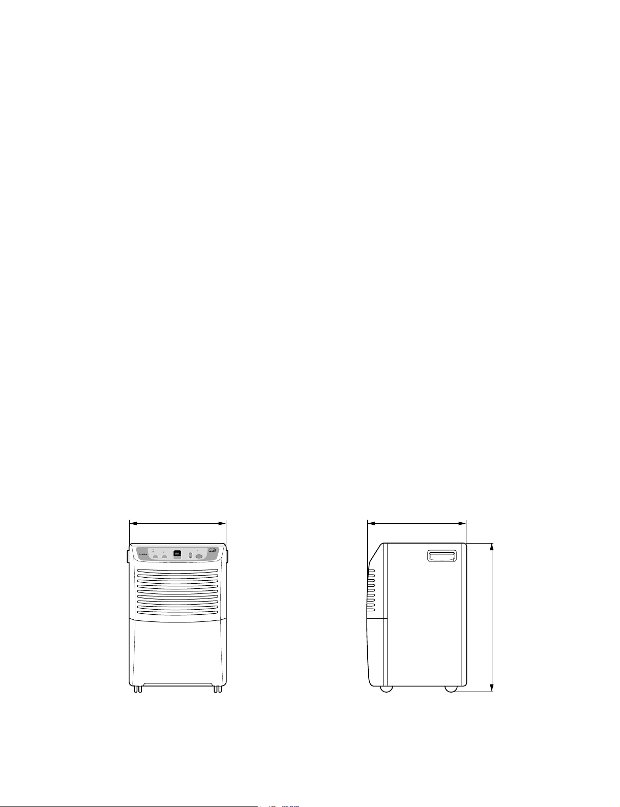
1.2.2 DIMENSIONS (mm/in)
Figure 1
385 (15
5
/
32
)
FAN
SPEED
TIMER
High
Low
Continuous On.
4Hr. On/Off
2Hr. On/Off
HUMIDITY
CONTROL
BUCKET
FULL
POWER
AUTO RESTART
HUMIDITY
SETTING
340 (13
3
/
8
)
540 (21
1
/
4
)
ENERGY STAR
Page 4
—4—
1.4 SPECIFICATIONS
1.3 MODEL NAMES
MODEL NAME
CAPACITY (Pints/24hrs) 30 40 50 65
MECHANICAL TYPE
ELECTRONIC TYPE
CONTROL
PANEL
DH305Y5, DH300MY5 DH400MY5,LD40Y5 - -
DH300EY5 DH404Y5 DH504ELY5 LD65ELY5
DH400EY5,LD40EY5 LD50ELY5
*NOTE:Specifications are subject to minor change without notice for further improvement.
DH305Y5, DH300MY5
DH300EY5
LD65ELY5*
POWER SUPPLY(Phase,V,Hz)
INPUT(W
) 480 58 0 560 850
RUNNING CURRENT(A) 4.8 5.7 5.4 8.3
ENERGY FACTOR(L/kw.h) 1.23 1.36 1.75 1.50
REFRIGERANT
REFRIGERANT CHARGE, oz(g) 3.53(100) 4.94(140) 7.93(225) 8.46(240)
OPEN
CLOSE
SOLENOID VALVE*
Using Temp/Humid.:-4~122°F(-20~50°C)/95%RH
Rating:7W/90mA
COMPRESSOR MODEL No. QS064CAB QS075CBA QA075CDB QA114CBD
PROTECTOR
CAPACITO
R 40µF, 270VAC 35µF, 270VAC 35µF, 270VAC
MOTOR ASSEMBLY,SINGL
E Shaded pole motor, 72W/1.4A, Thermal cutoff:266°F/130°C
Shaded pole motor, 91W/1.8A,
Thermal cutoff:266
°F/130°C
SWITCH ASSEMBLY,MICRO
OUTSIDED MENSIONS
WxHxD,mm(in)
NET WEIGHT,kg(lbs
) 17.6(38.9) 17.6(38.9) 20.4(44.9) 22.2(48.9)
OVERLOAD PROTECTOR FOR COMPRESSOR
INTERNAL PROTECTOR(FUSE)FOR MOTOR
1Ø, 115V,60Hz
R22
33.8°F(1±0.5°C)
50°F(10±0.5°C)
-
15A/250VAC
385X540X340(15 5/32 x 21 1/4 x 13 3/8)
MODELS
ITEMS
THERMISTOR
DH400MY5, LD40Y5
DH404EY5
DH400EY5, LD40EY5
-
DH504ELY5*
LD50ELY5*
35µF, 270VAC
Page 5
—5—
Humidity Control
• When you first use the dehumidifier, turn the humidity
control to 5 or 6. If you still have moisture, turn the
humidity control to a higher setting.
MAX is the highest setting.
• When excess moisture and dampness odors are
gone, adjust the control to a lower setting. Use the
dehumidifier as long as excess moisture is present.
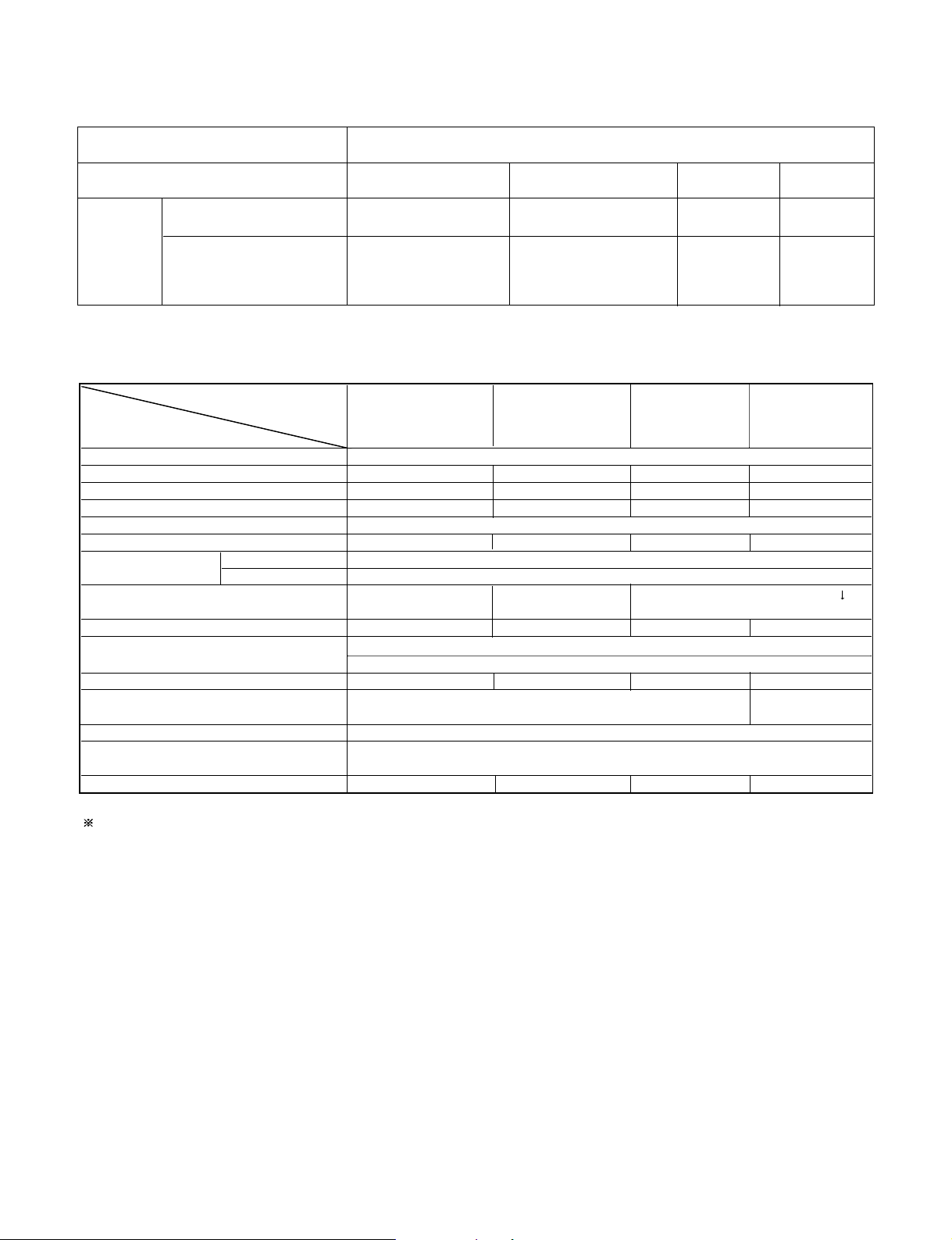
Fan Speed
• The fan control adjusts the fan speed.
Set the fan control to HIGH for maximum moisture
removal. When the humidity has been reduced and
quiet operation is preferred, set the fan control to
LOW.
Bucket Full Indicator
• This light glows when the water bucket is full and needs
to be emptied.
Power
• Operation starts when this button is pressed and stops
when the button is pressed again.
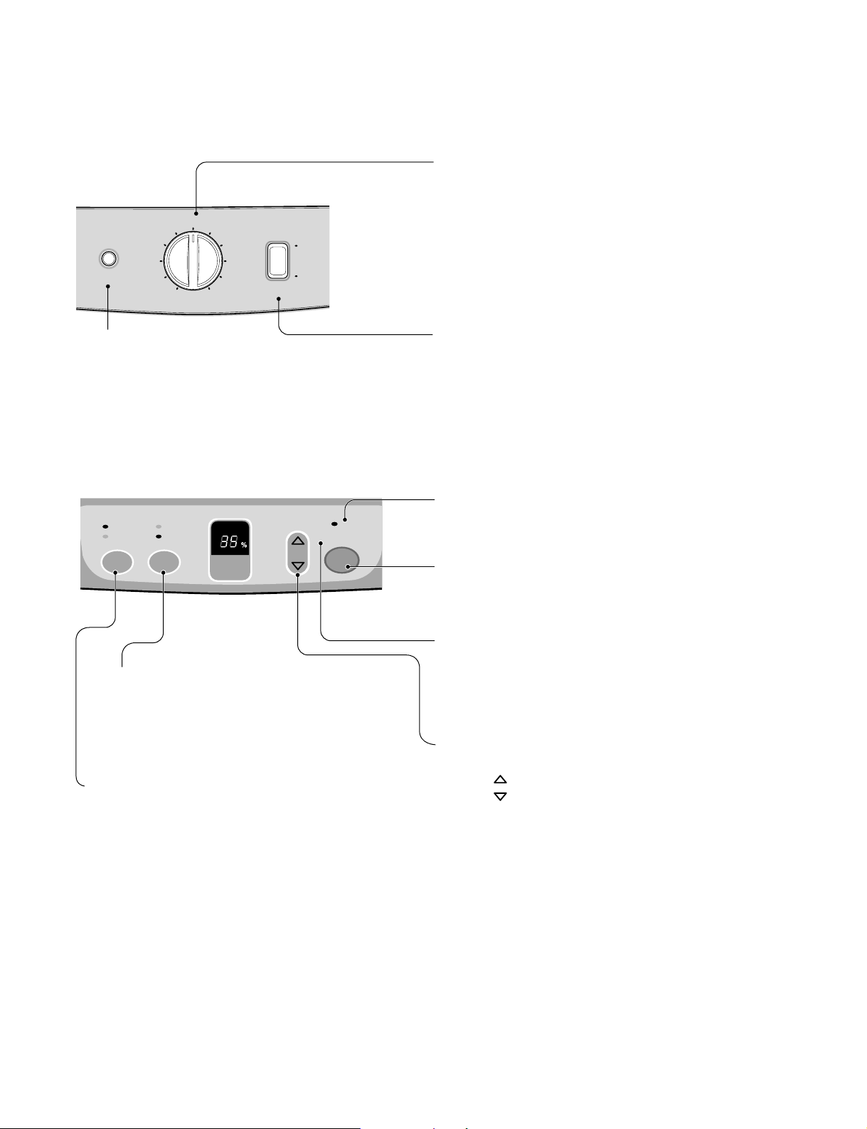
Auto Shut-Off
• This light glows when the bucket is full, or when
the bucket is removed or not placed in the proper
position. In these cases the Water Level Control
Switch shuts off the dehumidifier.
• When the light glows, check the bucket condition.
Fan Speed
• This controls the speed of the airflow.
• High: Fan speed is set to high.
• Low: Fan speed is set to low.
• When Fan Speed button is pressed, the fan speed
mode is changed.
Timer
• Press this button to select type of operation.
• Select continuous On for uninterrupted operation.
• Select either 2 or 4 hr. On/Off for cycled operation:
The unit will operate for 2 or 4 hours, and then shut
off completely for 2 or 4 hours.
The cycle repeats until you change the setting.
• When Timer button is pressed, the Timer indicator
lights shift as follow from 2hr.On/Off to 4hr.On/Off.
Auto Restart
•
Once power is restored after a power outage, the unit
returns to its previous operation setting after a 2 minute
delay.
The fan runs immediately when the power is restored.
Figure 2
Figure 3
Humidity Control
• This button controls the humidity in the room.
• Press button to raise the humidity setting.
• Press button to lower the humidity setting.
• The humidity setting can be set to a permanent "On"
setting or to a specific humidity setting between 35% and
70% in 5% increments.
• "On" setting: Dehumidifier runs continuously regardless
of humidity condition.
• 35% - 70% setting: Dehumidifier runs on and off
according to surrounding humidity conditions.
1.5 CONTROL TYPE
1.5.1 Mechanical type
1.5.2 Electronic type
5
6
4
3
2
Auto
Shut-Off
1
Off
Humidity Control
Constantly On.
4hr. On/Off
2hr. On/Off
TIMER
FAN
SPEED
High
Low
7
9
Max
HUMIDITY
SETTING
8
Fan Speed
HUMIDITY
CONTROL
High
Low
BUCKET
FULL
AUTO RESTART
POWER
Page 6
—6—
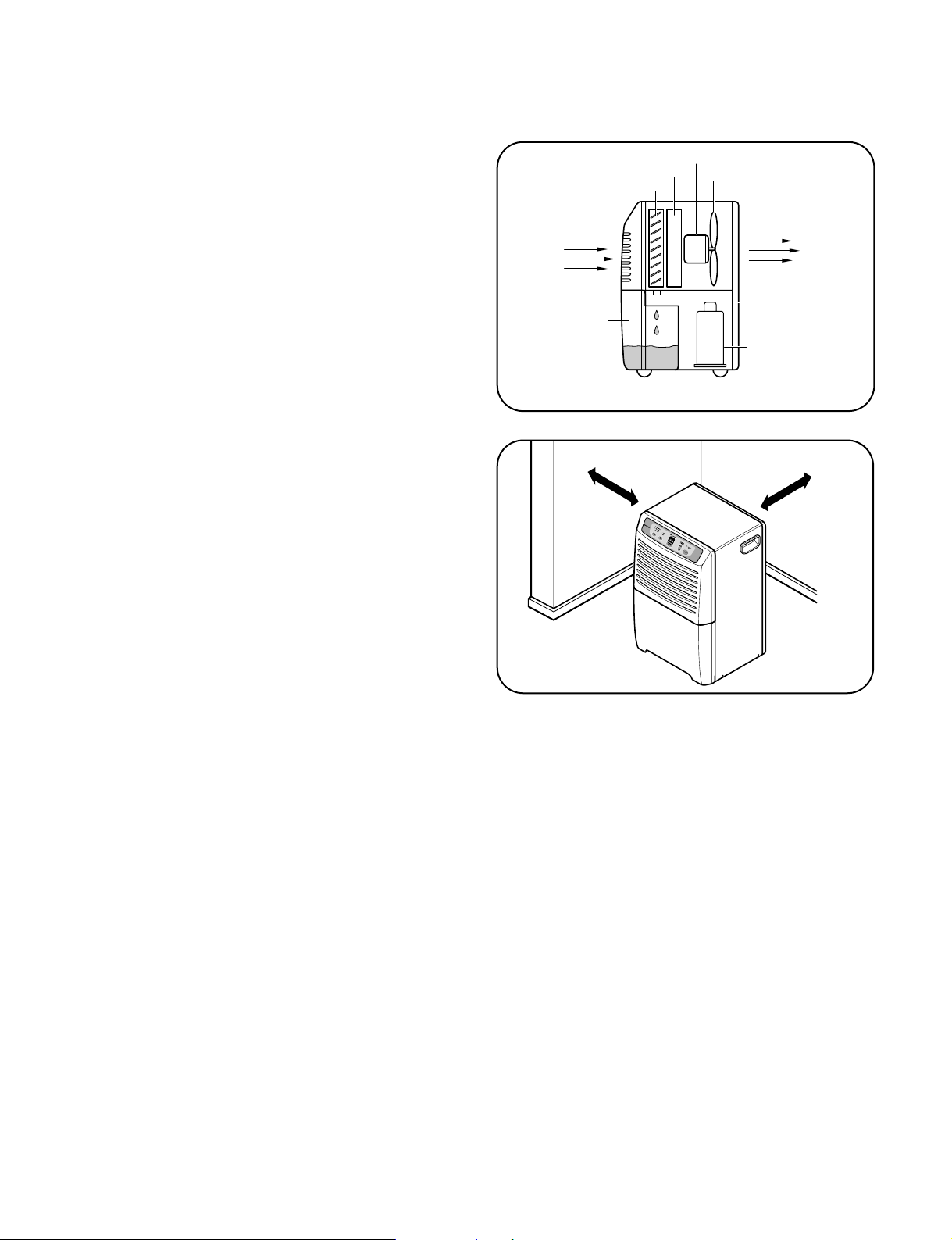
1.6.1 HOW DOES THE DEHUMIDIFIER WORK?
Moist, humid air is drawn over a cold refrigerated
dehumidifying coil. Moisture in the air condenses on this
coil and drains into a bucket (or through the bucket into a
hose and drain).
Dry, clean air is drawn over the condenser where it is
actually heated several degrees and discharged out the
rear grill into the room. (See Figure 4)
■ It is normal for the surrounding air to become
slightly warmer as the dehumidifier operates.
This warming effect further reduces the relative humidity
of the surrounding air.
1.6.2 LOCATION FOR THE DEHUMIDIFIER
Allow at least 12 inches of space on all sides of the
unit for good air circulation. (See Figure 5)
■ The dehumidifier must be operated in an enclosed
area to be most effective.
■ Close all doors, windows and other outside
openings to the room.
Place the dehumidifier in a location that does not
restrict air flow into the front grille or out the rear grille.
The operation of dehumidifier in a basement will have
little or no effect in drying an adjacent enclosed
storage area, such as a closet, unless there is
adequate circulation of air in and out of the area.
Fan
Side View
Condenser
Evaporator
Motor
Compressor
Rear Grille
Bucket
Dry
Air Out
Humid
Air In
12"
12"
Figure 4
Figure 5
1.6 HOW TO OPERATE DEHUMIDIFIER
1.6.3 MICRO SWITCH
The micro switch assembly, which is located on the drain pan of inside unit, automatically shuts off the dehumidifier when the
bucket is full (note, the Auto Shut Off lights, to indicate bucket must be emptied). The bucket replaces in its place, the unit again
turns itself on.
1.6.4 AUTO DEFROST
When frost builds up on the cooling coils, the unit will automatically cycle off until the frost disappears. The fan continues to run.
NOTE: The unit will not operate satisfactorily if the room temperature is below 65˚F(18˚C). If the dehumidifier is
operated in low temperature conditions frost can form in the evaporator coil and the unit will cycle ON/OFF
repeatedly. In this case, please check your room temperature conditions and stop the unit.
NOTE:
The low temperature operation feature in the DH504EL, DH50EL and DH65EL models will continuously cycle up to
a temperature of 42°F(6°C).
Page 7
—7—
1.6.5 HUMIDITY CONTROLLER
1.6.5.1 Mechanical Type
The humidity control can be set anywhere between Off and
Max for normal operation.
If you need more dehumidification, turn the Humidity Control
toward Max. If you need less dehumidification, turn the
Humidity Control toward Off.
The relative humidity range is from 20% to 80%. (See
Figure 6)
Turn the Humidity Control to Off to stop the unit manually.
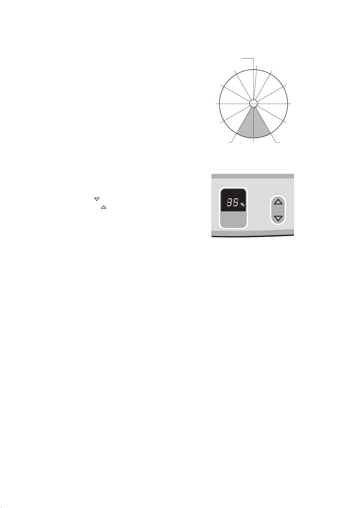
1.6.5.2 Electronic Type
The humidity control can be set 'on' or 35%-70%
RH(Relative Humidity) for normal operation. (See Figure 7)
If you need drier air, press the Humidity Control button.
If you need moister air, press the Humidity Control
button.
Press the Power button to stop the unit manually.
HUMIDITY
CONT
ROL
HUMIDITY
SETTING
42% R.H
40%
7(30%)
6(35%)4(50%)
3(60%)
2(70%)
1(80%)
5(42%)
8(25%)
9(20%)
Max.Off
DEAD DIAL
Figure 6
Figure 7
Page 8
—8—
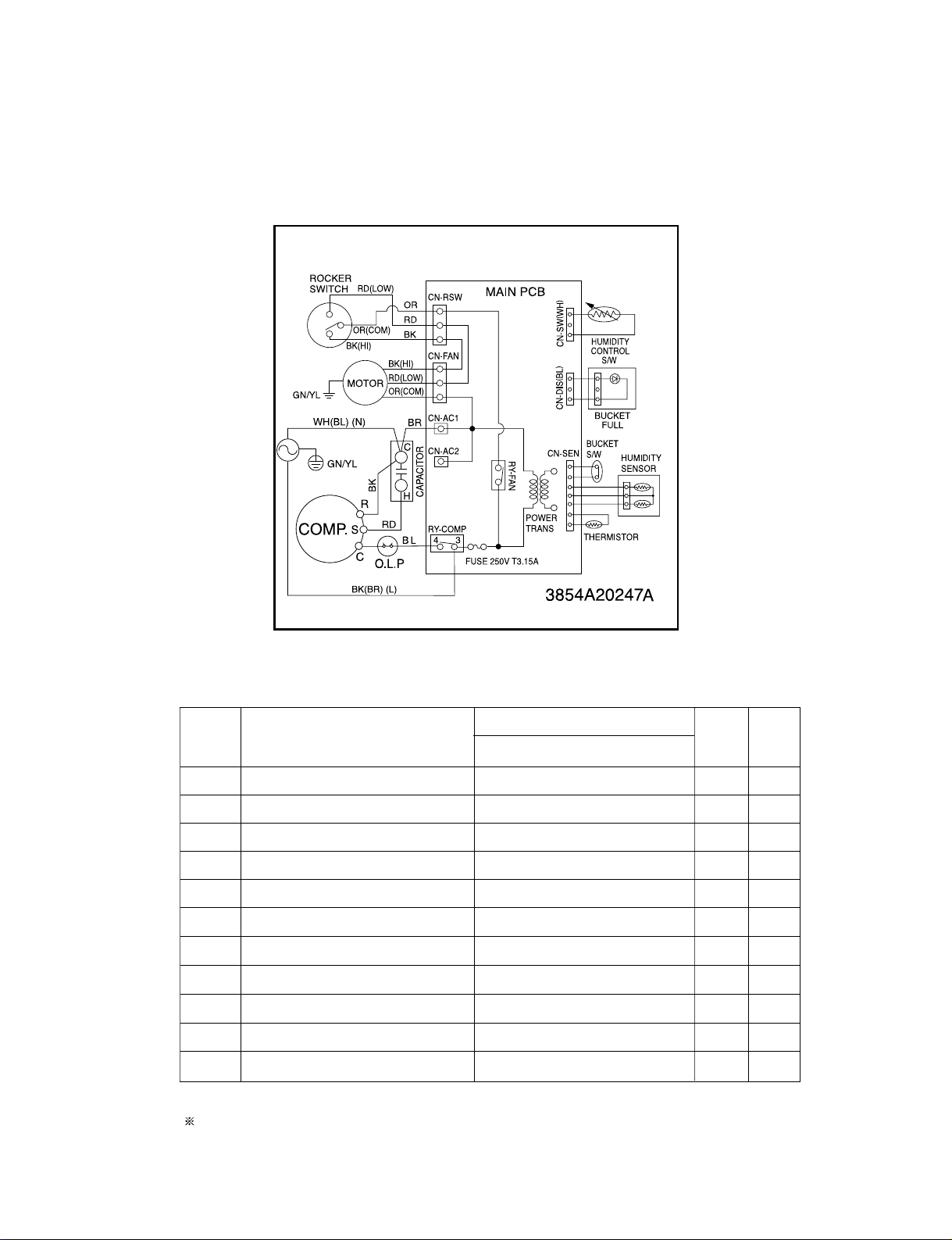
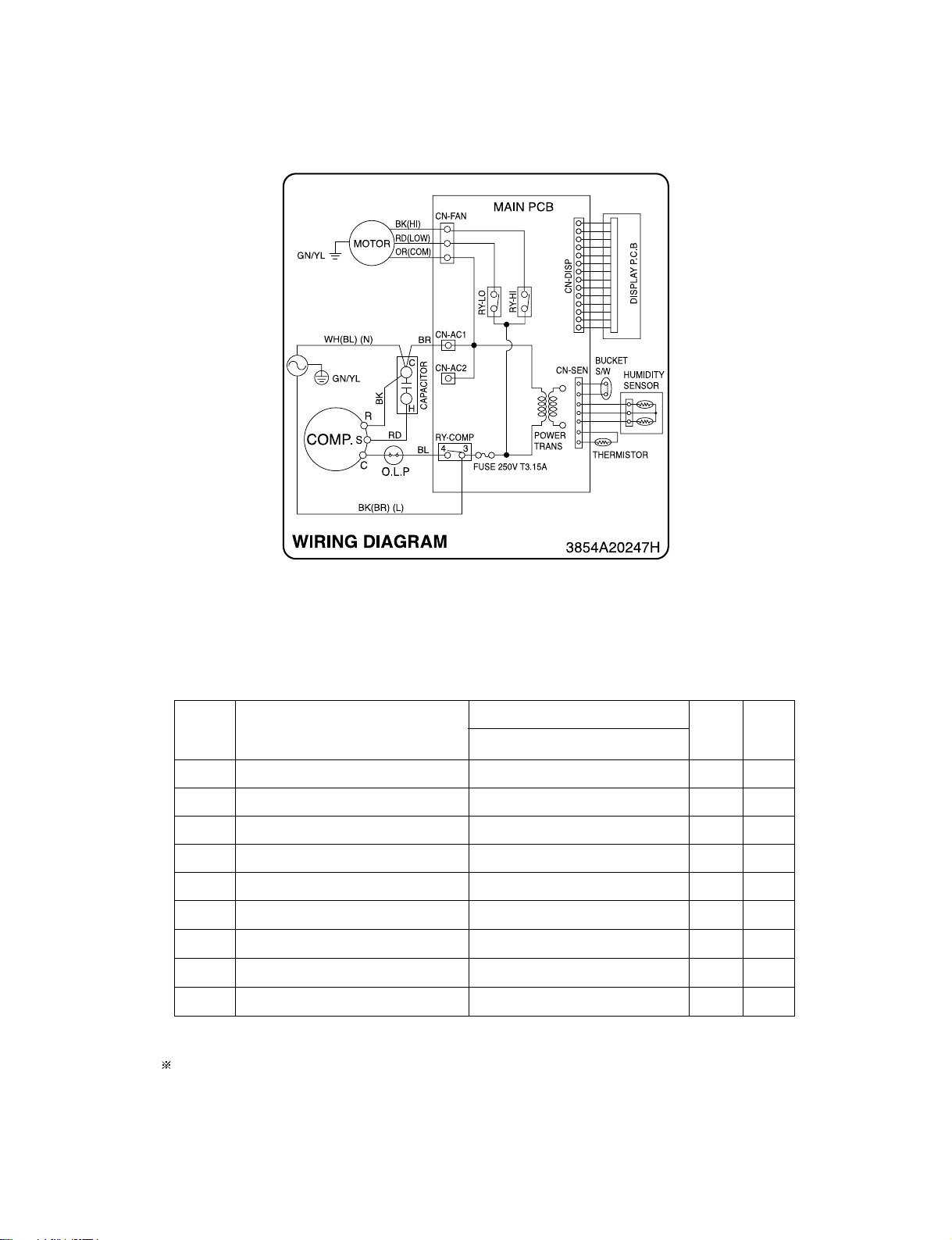
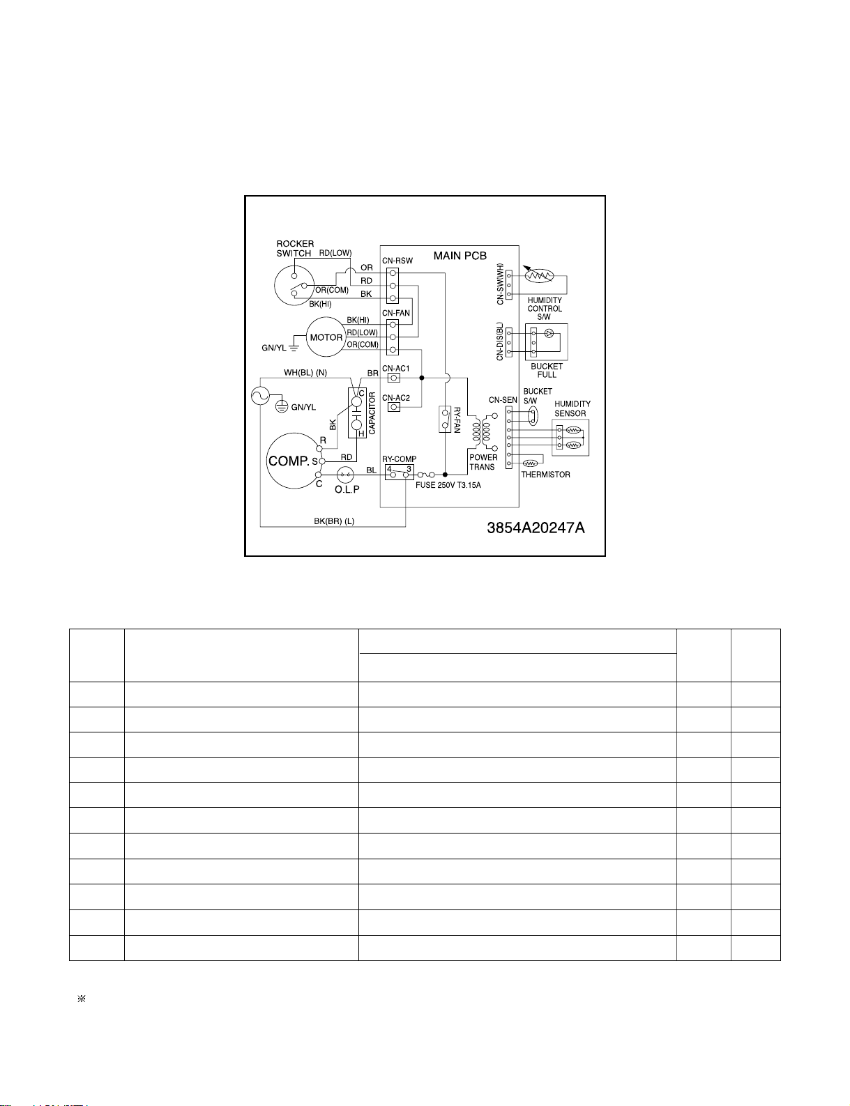
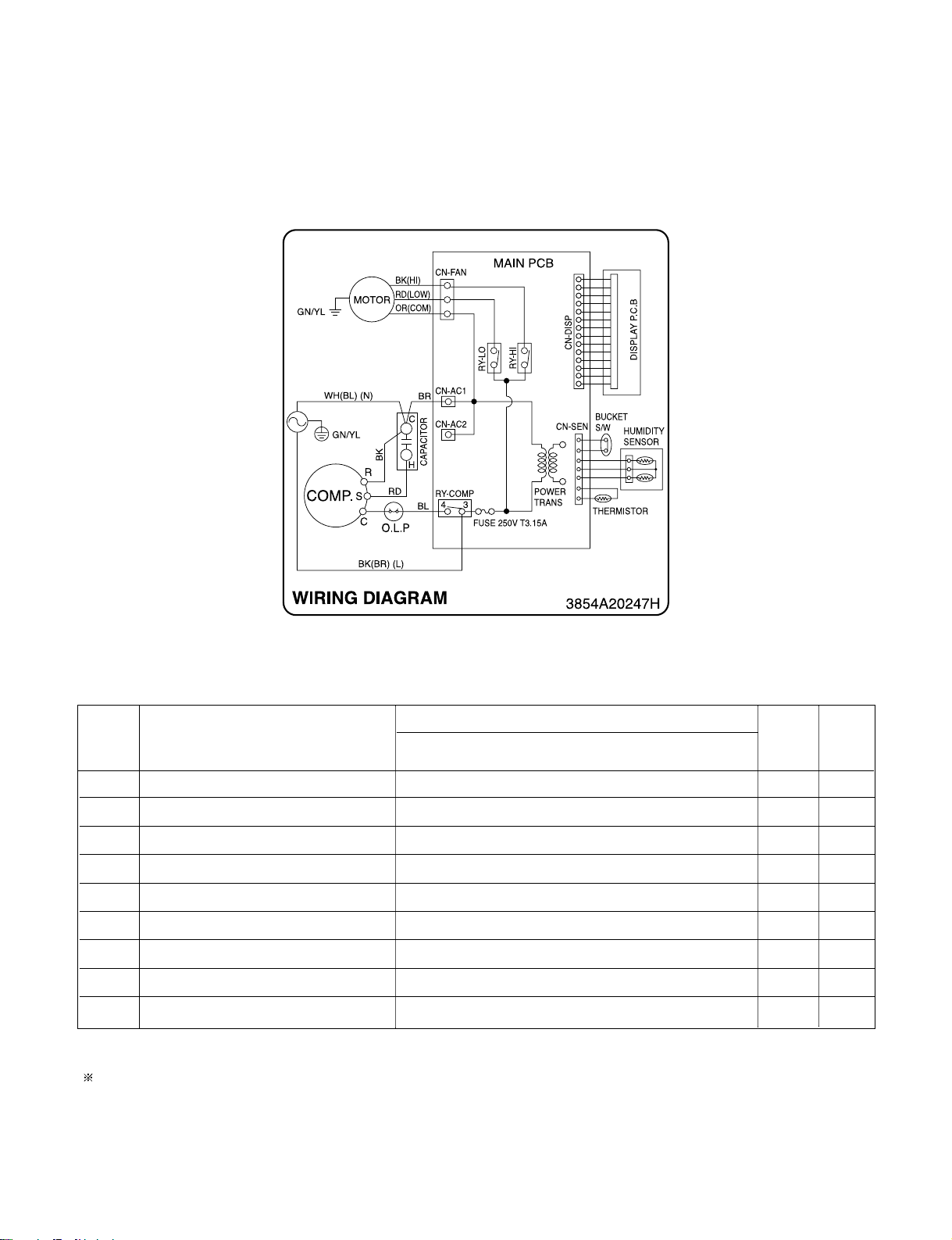
2. CIRCUIT DIAGRAM
• MODEL : DH305Y5, DH300MY5
Q'TY
PER SET
1
1
1
1
1
1
1
1
1
1
1
RE-
MARKS
S
S
S
S
S
S
S
S
S
S
S
1
2
3
4
5
6
7
8
9
10
11
DESCRIPTION
POWER CORD ASSEMBLY
SWITCH, ROCKER
MOTOR ASSEMBLY
CAPACITOR
COMPRESSOR, SET
OLP
PWB(PCB) ASSEMBLY, DISPLAY
SENSOR ASSEMBLY
SWITCH ASSEMBLY, ROTARY
SWITCH ASSEMBLY, MICRO
PWB(PCB) ASSEMBLY, MAIN
DH305Y5,DH300MY5
6411A20001Z
6600FX5001G
4681A20040Q
0CZZA20005J
2520UCBS005
6750U-L082A
6871A20289B
6877A30013L
6601A30001B
6600A30003C
6871A10142A
PART NO.
NO.
S: SERVICE PARTS A: ALTERNATE PARTS N: NOT SERVICE PARTS
Page 9
—9—
• MODEL : DH300EY5
S: SERVICE PARTS A: ALTERNATE PARTS N: NOT SERVICE PARTS
Q'TY
PER SET
1
1
1
1
1
1
1
1
1
RE-
MARKS
S
S
S
S
S
S
S
S
S
1
2
3
4
5
6
7
8
9
DESCRIPTION
POWER CORD ASSEMBLY
MOTOR ASSEMBLY
CAPACITOR
COMPRESSOR, SET
OLP
PWB(PCB) ASSEMBLY, DISPLAY
SENSOR ASSEMBLY
SWITCH ASSEMBLY, MICRO
PWB(PCB) ASSEMBLY, MAIN
DH300EY5
6411A20001Z
4681A20040Q
0CZZA20005J
2520UCBS005
6750U-L082A
6871A20482A
6877A30013L
6600A30003C
6871A10141A
PART NO.
NO.
Page 10
—10—
• MODEL : DH400MY5/LD40Y5
Q'TY
PER SET
1
1
1
1
1
1
1
1
1
1
1
RE-
MARKS
S
S
S
S
S
S
S
S
S
S
S
1
2
3
4
5
6
7
8
9
10
11
DESCRIPTION
POWER CORD ASSEMBLY
SWITCH, ROCKER
MOTOR ASSEMBLY
CAPACITOR
COMPRESSOR (ROTARY), SET
OLP (ASSEMBLY)
PWB(PCB) ASSEMBLY, DISPLAY
SENSOR ASSEMBLY
SWITCH ASSEMBLY, ROTARY
SWITCH ASSEMBLY, MICRO
PWB(PCB) ASSEMBLY, MAIN
DH400MY5/LD40Y5
6411A20001Z
6600FX5001G
4681A20040J
0CZZA20005N
2520UCAS003
6750U-L103A
6871A20289B
6877A30013M
6601A30001C
6600A30003C
6871A10142A
PART NO.
S: SERVICE PARTS A: ALTERNATE PARTS N: NOT SERVICE PARTS
NO.
Page 11
—11—
• MODEL :DH404EY5/DH400EY5/LD40EY5
Q'TY
PER SET
1
1
1
1
1
1
1
1
1
RE-
MARKS
S
S
S
S
S
S
S
S
S
1
2
3
4
5
6
7
8
9
DESCRIPTION
POWER CORD ASSEMBLY
MOTOR ASSEMBLY
CAPACITOR
COMPRESSOR,SET
OLP
PWB(PCB) ASSEMBLY,DISPLAY
SENSOR ASSEMBLY
SWITCH ASSEMBLY,MICRO
PWB(PCB) ASSEMBLY,MAIN
DH404EY5/DH400EY5
LD40EY5
6411A20001Z
4681A20040J
0CZZA20005N
2520UCAS003
6750U-L103A
6871A20482A
6877A30013M
6600A30003C
6871A10141A
PART NO.
S: SERVICE PARTS A: ALTERNATE PARTS N: NOT SERVICE PARTS
NO.
Page 12

—12—
• MODEL : DH504ELY5/LD50ELY5/LD65ELY5
Q'TY
PER SET
1
1
1
1
1
1
1
1
1
1
RE-
MARKS
S
S
S
S
S
S
S
S
S
S
1
2
3
4
5
6
7
8
9
10
DESCRIPTION
POWER CORD ASSEMBLY
MOTOR ASSEMBLY
CAPACITOR
COMPRESSOR (ROTARY), SET
OLP.
PWB(PCB) ASSEMBLY, DISPLAY
SENSOR ASSEMBLY
SWITCH ASSEMBLY, MICRO
PWB(PCB) ASSEMBLY, MAIN
COIL ASSEMBLY, SOLENOID
DH504ELY5/LD50ELY5
LD65ELY5
6411A20001Z
4681A20040J 4681A20040K
0CZZA20005J 0CZZA20005J
2520UCBA010 2520UCBA007
6750U-L001A 6750U-L048A
6871A20482A
6877A30013L
6600A30003C
6871A10141C
6421A20003K
PART NO.
S: SERVICE PARTS A: ALTERNATE PARTS N: NOT SERVICE PARTS
NO.
Page 13

3.1 MECHANICAL PARTS
3.1.1 BUCKET AND AIR FILTER
1. Turn the Humidity Control off(Mechanical type) or
press the power button off. (Electronic type)
2. Disconnect the power supply.
3. Remove the bucket. (See Figure 9)
4. Pull out the air filter.
(See Figure 10)
3.1.2 FRONT CASE AND REAR GRILLE
1. Remove 2 screws which fasten the front grille.
2. Pull the front grille forward and upward.
(See Figure 11)
3. Remove 6 screws that secure the rear grille.
4. Remove the rear grille. (See Figure 12)
3.1.3.
CABINET AND CONTROL BOX
1. Remove the Bucket, the Air filter and Front grille
according to the procedure above.
2. Remove 1 screws that fasten Control box.
(See Figure 13)
3. Remove 8 screws on all sides of the cabinet.
4. Lift the Cabinet from the base.(See Figure 13)
5. Remove a screw fasten the earth wire on the inside
of control box.
6. Remove 1 screw that fasten control box and
unhook control box from hook on the shroud.
(See Figure 14)
—13—
3. DISASSEMBLY INSTRUCTIONS
Figure 9 Figure 10
Figure 11 Figure 12
Figure 13 Figure 14
Page 14

3.2 CONTROL PARTS
3.2.1 POWER CORD ASSEMBLY
1. After opening the control box, remove the screw
that holds the ground wire. (See Figure 15)
2. Disconnect the remaining leads of the power cord
from the PWB(PCB) ASSEMBLY, MAIN, then
remove it from the control box.
3.2.2 SENSOR ASSEMBLY
1. Disconnect the sensor assembly from the
PWB(PCB) ASSEMBLY, MAIN.
2. Remove the screw which fastens the humidity
sensor. (See Figure 16)
3. Remove the thermistor from the holder.
(See Figure 16)
4. Disconnect the switch wires from the micro switch
assembly. (See Figure 16)
3.2.3 PWB(PCB) ASSEMBLY, MAIN
1.
Disconnect all leads of the motor and the compressor
from PWB(PCB) ASSEMBLY, MAIN.
2. Remove the screw which fastens the PWB(PCB)
ASSEMBLY, MAIN and pull it out after unhooking
from 2 rectangular holes of the control box (lower).
(See Figure 17)
3.2.4 CAPACITOR
1. Remove the screw that fastens the capacitor.
(See Figure 17)
2. Disconnect all leads from the capacitor and then
remove it from control box.
3.2.5 MICRO SWITCH ASSEMBLY
1. Turn the nut counterclockwise and pull out the
micro switch from the drain pan. (See Figure 18)
—14—
Figure 17
Figure 16
Figure 18
Figure 15
Page 15

—15—
3.2.6 COIL ASSEMBLY, SOLENOID
(DH504ELY5, LD50ELY5, LD65ELY5)
1. Disconnect the housing of the COIL ASSEMBLY,
SOLENOID from the PCB(PWB) ASSEMBLY,
MAIN.
2. Remove the screw that fastens the COIL
ASSEMBLY, SOLENOID. (See Figure 19)
3. Pull it out upwards.
3.2.7 CONTROL PANEL
3.2.6.1 CONTROL PANEL - Mechanical Type
(DH305Y5/DH300MY5/DH400MY5/LD40Y5)
1. Disconnect housing and all leads of the rocker
switch, SWITCH ASSEMBLY, ROTARY and
PWB(PCB) ASSEMBLY, DISPLAY from PWB(PCB)
ASSEMBLY, MAIN (3.1.3)
2. Pull out the knob assembly.
3. Remove the nut which fastens the SWITCH
ASSEMBLY, ROTARY.
4. Remove the knob of the rotary switch by pulling it
upward.
5. Pull out the rocker switch by pushing the hooks on
the both sides of rocker switch.
6. Pull out the PWB(PCB) ASSEMBLY, DISPLAY after
turning over both hooks of the display cover.
1. Disconnect the housing of the PWB(PCB)
ASSEMBLY, DISPLAY from PWB(PCB)
ASSEMBLY, MAIN (3.1.3).
2. Remove 6 screws that secure the PWB(PCB)
ASSEMBLY, DISPLAY to the display cover.
Figure 19
Figure 20
H
i
g
h
L
o
w
Fan Speed
H
um
idity Control
Auto
Shut-O
ff
E
N
E
R
G
Y
S
T
A
R
M
a
x
O
f
f
Figure 21
3.2.6.2 CONTROL PANEL - Electronic Type
(DH300EY5/DH404EY5/DH400EY5/LD40EY5/DH504ELY5/
LD50ELY5/LD65ELY5)
Page 16

3.2.8
FAN AND MOTOR
1. Turn the nut left and full out the Fan by hands
carefully.
2. Remove 2 screws that fasten Heat Exchange.
3. Lift the H/E and open the H/E around 45 degree
clockwise carefully. (See Figure 22)
4. Unfasten 3 screws that secure the Motor and earth
wire. (See Figure 23)
5. Remove the Motor.
3.2.9
SHROUD AND DRAIN PAN
1. Discharge the refrigerant by using a refrigerant
Recovery System.
2. After purging the unit completely, unbrace the
Discharge and the Suction tube connected
compressor carefully.
3. Remove 2 screws that fasten the H/E.
4. Unfasten 2 screws that secure the shroud on the
sides and then lift shroud from the drain pan.
(See Figure 24)
5. Unfasten 2 screws that secure the drain pan to
base pan. (See Figure 25)
6. Pull the drain pan backward then take it up from the
base. (See Figure 25)
—16—
Figure 25
Figure 22
Figure 23
Figure 24
Page 17

—17—
3.3 REFRIGERATING CYCLE
3.3.1 CONDENSER, EVAPORATOR AND
CAPILLARY TUBE
1. Remove the insulation on the Heater/Evaporator
(H/E) assembly
2. Pierce the pinch-off tube to discharge the
refrigerant, using a refrigerant recovery system.
3. After discharging the refrigerant completely,
remove 2 screws between the housing assembly
and the H/E. (See Figure 26)
4. Lift the H/E and open the H/E around 45 degree
counterclockwise carefully.
5. Unbraze each of interconnecting tubes of the
evaporator and condenser carefully.
6. Remove the H/E assembly from the orifice.
(See Figure 27)
7. Unbraze the capillary tube at the connections of the
condenser and evaporator. (See Figure 28)
8. Remove 4 screws between the condenser and
evaporator. (See Figure 28)
3.3.2 COMPRESSOR
1. Discharge the refrigerant by using a refrigerant
Recovery System.
2. After purging the unit completely, unbraze the
suction and discharge tubes at the compressor
connections.
3. Remove the nuts and washers which fasten the
compressor. (See Figure 29)
4. Remove the compressor. (See Figure 29)
Figure 26
Figure 27
Figure 28
Using Rotary
Compressor models
Figure 29
Page 18

—18—
1. When replacing a refrigeration component, be sure
to discharge the refrigerant system by using a
refrigerant recovery system.
2. After discharging the unit completely, remove the
desired component, and unbraze the pinch-off
tubes.
3. Solder service valves into the pinch-off tube ports,
leaving the valves open.
4. Solder the pinch-off tubes with service valves.
5. After doing the above procedures, the valve must
be closed and left in place on the system for any
subsequent procedures.
6. Evacuate as follows.
1) Connect the vacuum pump, as illustrated in
Figure 31A.
2) Start the vacuum pump, slowly open manifold
valves A and B two full turns counterclockwise
and leave the valves open.
The vacuum pump is now pulling through valves
A and B to valve C by means of the manifold
and entire system.
3) Operate the vacuum pump for 20 to 30 minutes,
until 600 microns of vacuum are obtained. Close
valves A and B, and observe vacuum gauge for
a few minutes. A rise in pressure would
indicate a possible leak or moisture remaining in
the system. With valves A and B closed, stop
the vacuum pump.
4) Remove the hose from the vacuum pump and
place it on the charging cylinder. See Figure 31B.
Open valve C.
Discharge the line at the manifold connection.
5) The system is now ready for final charging.
7. Recharge as follows :
1) Refrigeration cycle systems are charged from the
High-side. If the total charge cannot be put
in the High-side, the balance will be put in the
suction line through the access valve which you
installed as the system was opened.
2) Connect the charging cylinder as shown in Figure
31B.
With valve C open, discharge the hose at the
manifold connection.
3) Open valve A and allow the proper charge to
enter the system. Valve B is still closed.
4) If more charge is required, the high-side will not
take it. Close valve A.
5) With the unit running, open valve B and add the
balance of the charge.
a. Do not add the liquid refrigerant to the Low-
side.
b. Watch the Low-side gauge; allow pressure to
rise to 30 lbs.
c. Turn off valve B and allow pressure to drop.
d. Repeat steps B and C until the balance of the
charge is in the system.
6) When satisfied the unit is operating correctly,
use the pinch-off tool with the unit still running
and clamp on to the pinch-off tube. Using a tube
cutter, cut the pinch-off tube about 2 inches from
the pinch-off tool. Use sil-fos solder and solder
pinch-off tube closed. Turn off the unit, allow it to
set for a while, and then test the leakage of the
pinch-off connection.
If
high vacuum equipment is used, just crack
valves A and B for a few minutes, then open
slowly
with the two full turns counterclockwise.
This will keep oil from foaming and being drawn
into the vacuum pump.
CAUTION
3.4 HOW TO REPLACE THE REFRIGERATION SYSTEM
Page 19

—19—
Equipment needed: Vacuum pump, charging cylinder, manifold gauge, brazing equipment. pinch-off tool capable
of making a vapor-proof seal, leak detector, tubing cutter, hand tools to remove components, service valve.
B
A
COMPRESSOR
COMPOUND GAUGE
MANIFOLD
GAUGE
SEE INSETS
BELOW
EXTERNAL
VACUUM PUMP
CHARGING
CYLINDER
HILOW
A
B
A
B
C
CONDENSER ASSEMBLY
(HIGH PRESSURE SIDE)
EVAPORATOR ASSEMBLY
(LOW PRESSURE SIDE)
CAPILLARY
TUBE
Figure 31A-Pulling Vacuum
Figure 31B-Charging
Page 20

CONDITION
1. Dehumidifier does not start. (Both
compressor and fan motor do not
operate.)
2. Motor runs but compressor does not
run.
3. Does not defrost control.
4. Insufficient dehumidification
CAUSE
No power
Poor plug contact at outlet.
Bucket is full.
Humidity control is at Off position
Wire disconnected or loose
Capacitor.
(Discharge capacitor before testing.)
Voltage (115V ± 10%)
Wiring
Rotary switch
Defrost control
Capacitor
(Discharge capacitor before servicing.)
Compressor
Overload protector (OLP)
Defrost control is defective.
Low relative humidity
Poor air circulation
H/E clogged with dust and dirt
Air filter is dirty.
Motor is not operating.
REMEDY
C
heck power supply at outlet.
Correct if none.
Install plug properly or replace it.
If Auto Shut Off lights, empty the bucket
and replace properly.
Turn the humidity control switch toward
Max.
Connect wire. Refer to wiring diagram for
terminal identification. Repair or replace
loose terminal.
Test capacitor.
Replace if not within ±10% of
manufacturer's rating. Replace if shorted,
open, or damaged.
It must be between 103.5V and 126.5V. If
not within limits, call an electrician
Check the wire connections; If loose,
repair or replace the terminal. If the wires
are disconnected, refer to wiring diagram
for identification, and replace the wires.
Check the wire connections; If not
according to the wiring diagram, correct
the connections.
Check for continuity, refer to the wiring
diagram for terminal identification. Replace
the switch if the circuit is open.
The Defrost Control senses frost build-up
on the evaporator coil and automatically
shuts off the compressor. The fan
continues to run, drawing air across the
coil, and melting the frost. When the coil is
defrosted, the compressor automatically
restarts, and dehumidifying resumes.
Check the capacitor.
Replace if not within ±10% of
manufacturer's rating. Replace if shorted,
open, or damaged.
Check the compressor for open circuit or
ground. If open or grounded, replace the
compressor.
Check the compressor OLP if externally
mounted. Replace if open. (If the
compressor temperature is high, remove
OLP, cool, and retest.)
Check defrost control, replace it.
Turn dehumidifier off.
Move dehumidifier to obtain free and
unobstructed air circulation.
Clean evaporator and/or condenser assembly
Clean it.
Check Motor, repair or replace it.
—20—
4. TROUBLESHOOTING GUIDE
Page 21

—21—
CONDITION
5. Noisy operating
6. Water drips
7. Compressor cycles on overload
protector. (OLP)
CAUSE
Fan
Loose foreign material inside the housing.
Tube hits frame.
Fan blade hits frame
Internal compressor noise.
Loose set screws
Worn bearings of Motor Assembly
The bucket is not installed properly.
Connection may be loose.
Leak in bucket
Water drips when bucket removed for
emptying.
Bucket overflows.
High or low line voltage. (115V
± 10%)
Poor air circulation.
Heat Exchange clogged with dust or dirt.
Motor
Short circuit or ground in electrical circuit
Unit pressures not equalized
Capacitor
Wiring
Refrigeration system
Stuck compressor
Overload protector (OLP)
REMEDY
If cracked, out of balance, or partially
missing, replace it
Remove it.
Adjust tubing routine carefully.
Check Motor Mount. If loose, tighten it.
Replace compressor.
Tighten them.
If knocking sounds continue when running
or loose, replace the motor. If the motor
hums or noise appears to be internal while
running, replace motor assembly.
The bucket should be properly positioned
on the hangers of the drain pan.
Check connection and repair.
Replace bucket.
Before removing bucket, the unit should
be turned off.
Check micro switch and float.
Check line voltage. It must be between
103.5V and 126.5V volts.
If intermittent, provide new supply.
Move dehumidifier for free and
unobstructed air flow.
Clean dust or dirt on the Heat Exchange.
If not running, determine the cause.
Replace if required.
Check electrical circuit. Repair.
Allow 2 or 3 minutes for pressure to
equalize before starting compressor.
Test the capacitor.
Check the terminals. If loose, repair or
replace.
Check the system for a restriction.
Check compressor, replace compressor
Check OLP, if externally mounted.
Replace if open. (If the compressor
temperature is high, remove the OLP,
cool, and retest.)
Page 22

—22—
5. EXPLODED VIEWS
• MODEL: DH305Y5/DH300MY5
354210
554030
131400
349600
149980
165010
346811
359012
264110
148391
144410
752140
152302
436500
249950
266010
130410
235512
149410
435300
330870
266003
238310
135312
268711-1
266002
1
2
3
4
5
6
7
8
9
O
f
f
M
a
x
H
g
i
h
L
o
w
d
e
e
p
S
n
a
F
l
o
r
t
n
o
C
y
t
i
d
i
m
u
H
A
u
t
o
S
h
u
t
O
f
f
W0CZZ-2
268711-2
352113
35211A
552111
567502
554160
550140
Page 23

—23—
• MODEL: DH300EY5
354210
554030
131400
349600
149980
165010
346811
359012
264110
148391
144410
752140
436500
249950
266010
130410
435300
330870
135312
W0CZZ-2
268711-2
235512
268711-1
238310
152302
352113
35211A
552111
567502
554160
550140
Page 24

—24—
• MODEL: DH400MY5/LD40Y5
W0CZZ-2
165010
268711-2
264110
249950
352113
552111
550140
567502
554160
354210
554030
131400
349600
149980
346811
359012
148391
144410
752140
152302
436500
266010
130410
235512
149410
435300
330870
266003
238310
135312
268711-1
266002
H
i
g
h
L
o
w
d
e
e
p
S
n
a
F
m
u
H
o
C
y
t
i
d
i
l
o
r
t
n
o
t
u
A
O
-
t
u
h
S
f
f
E
N
E
R
G
Y
S
T
A
R
M
a
x
O
f
f
35211A
Page 25

—25—
• MODEL: DH404EY5/DH400EY5/LD40EY5
W0CZZ-2
165010
268711-2
264110
249950
352113
552111
550140
567502
554160
354210
554030
135312
131400
349600
149980
346811
359012
148391
144410
752140
152302
436500
130410
235512
266010
238310
435300
330870
268711-1
35211A
Page 26

—26—
• MODEL: DH504ELY5/LD50ELY5
W0CZZ-2
165010
268711-2
264110
249950
35211A
352113
552204
567502
554160
550140
354210
554030
135312
131400
349600
149980
346811
359012
148391
144410
752140
152302
436500
130410
266010
238310
435300
330870
235512
268711-1
Page 27

—27—
• MODEL: LD65ELY5
W0CZZ-2
165010
268711-2
264110
249950
35211A
552204
352113
567502
554160
550140
354210
135312
554030
131400
349600
149980
346811
359012
148391
144410
752140
152302
436500
130410
266010
238310
435300
330870
235512
268711-1
Page 28

—28—
6. REPLACEMENT PARTS LIST
• MODEL: DH305Y5/DH300MY5
130410 BASE ASSEMBLY 3041A10042A
131400 CABINET 3090A10042A
135312 FRONT GRILLE,ASSEMBLY 3531A10285C
330870 DRAIN PAN ASSEMBLY 3087A10019C
148391 TANK ASSEMBLY,BUCKET 4839A10002A
149410 KNOB ASSEMBLY 4941A30019B
152302 FILTER(MECH),AIR 5230A20040A
165010 SENSOR ASEMBLY 6877A30013L
249950 CONTROL BOX,ASSEMBLY 4995A20359U
264110 POWER CORD,ASSEMBLY 6411A20001Z
266002 SWITCH,ROCKER 6600FX5001G
266003 SWITCH ASSEMBLY,ROTARY 6601A30001B
266010 SWITCH ASSEMBLY,MICRO 6600A30003C
268711-1 PWB(PCB)ASSEMBLY,DISPLAY 6871A20289B
268711-2 PWB(PCB)ASSEMBLY,MAIN 6871A10142A
346811 MOTOR ASSEMBLY 4681A20040Q
35211A TUBE ASSEMBLY,SUCTION 5211A11057A
352113 TUBE ASSEMBLY,DISCHARGE 5211A11056A
552111 TUBE ASSEMBLY,CAPILLARY 5211A31023B
354210 EVAPORATOR,ASSEMBLY 5421A10009P
554030 CONDENSOR ASSEMBLY 5403A10008B
W0CZZ-2 CAPACITOR 0CZZA20005J
554160 COMPRESSOR ,SET 2520UCBS005
359012 FAN,TURBO 5900A20007A
567502 OLP 6750U-L082A
349600 MOUNT,MOTOR 4960A20009B
436500 HANDLE 3650A20004A
144410 CASTER ASSEMBLY,ROLLER 4441A30001B
238310 ESCUTCHEON 3831A20079M
235512 COVER ASSEMBLY,DISPLAY 3551A20122A
752140 HOSE,CONNECTOR 5214A20027B
550140 BUSHING 4830A30005A
149980 SHROUD 4998A10034A
435300 REAR GRILLE 3530A10193B
LOCATION
NO.
DESCRIPTION
REMARK
PART NO.
DH305Y5/DH300MY5
Page 29

—23—
• MODEL: DH300EY5
130410 BASE ASSEMBLY 3041A10042A
131400 CABINET 3090A10042A
135312 FRONT GRILLE,ASSEMBLY 3531A10254F
330870 DRAIN PAN ASSEMBLY 3087A10019C
148391 TANK ASSEMBLY,BUCKET 4839A10002A
152302 FILTER(MECH),AIR 5230A20040A
165010 SENSOR ASEMBLY 6877A30013L
249950 CONTROL BOX,ASSEMBLY 4995A20359S
264110 POWER CORD,ASSEMBLY 6411A20001Z
266010 SWITCH ASSEMBLY,MICRO 6600A30003C
268711-1 PWB(PCB)ASSEMBLY,DISPLAY 6871A20482A
268711-2 PWB(PCB)ASSEMBLY,MAIN 6871A10141A
346811 MOTOR ASSEMBLY 4681A20040Q
35211A TUBE ASSEMBLY,SUCTION 5211A11057A
352113 TUBE ASSEMBLY,DISCHARGE 5211A11056A
552111 TUBE ASSEMBLY,CAPILLARY 5211A31023B
354210 EVAPORATOR,ASSEMBLY 5421A10009P
554030 CONDENSOR ASSEMBLY 5403A10008B
558511 DRIER ASSEMBLY 5851A30001A
554160 COMPRESSOR ,SET 2520UCBS005
359012 FAN,TURBO 5900A20007A
567502 OLP 6750U-L082A
349600 MOUNT,MOTOR 4960A20009B
CAPACITOR 0CZZA20005J
436500 HANDLE 3650A20004A
144410 CASTER ASSEMBLY,ROLLER 4441A30001B
238310 ESCUTCHEON 3831A20079L
235512 COVER ASSEMBLY,DISPLAY 3551A20109B
752140 HOSE,CONNECTOR 5214A20027B
550140 BUSHING 4830A30005A
149980 SHROUD 4998A10034A
435300 REAR GRILLE 3530A10193B
LOCATION
NO.
DESCRIPTION
REMARK
PART NO.
DH300EY5
W0CZZ-2
Page 30

—30—
• MODEL: DH400MY5/LD40Y5
130410 BASE ASSEMBLY 3041A10042B
131400 CABINET 3090A10042A
135312 FRONT GRILLE,ASSEMBLY 3531A10285E / 3531A20285B "B:LG/E:Goldstar"
330870 DRAIN PAN ASSEMBLY 3087A10019C
148391 TANK ASSEMBLY,BUCKET 4839A10002A
149410 KNOB ASSEMBLY 4941A30019B
152302 FILTER(MECH),AIR 5230A20040A
165010 SENSOR ASEMBLY 6877A30013M
W0CZZ-2 CAPACITOR 0CZZA20005N
249950 CONTROL BOX,ASSEMBLY 4995A20359H
264110 POWER CORD,ASSEMBLY 6411A20001Z
266002 SWITCH,ROCKER 6600FX5001G
266003 SWITCH ASSEMBLY,ROTARY 6601A30001B
266010 SWITCH ASSEMBLY,MICRO 6600A30003C
268711-1 PWB(PCB)ASSEMBLY,DISPLAY 6871A20289B
268711-2 PWB(PCB)ASSEMBLY,MAIN 6871A10142A
346811 MOTOR ASSEMBLY 4681A20040J
35211A TUBE ASSEMBLY,SUCTION 5211A11057B
352113 TUBE ASSEMBLY,DISCHARGE 5211A10463A
552111 TUBE ASSEMBLY,CAPILLARY 5211A31003B
354210 EVAPORATOR,ASSEMBLY 5421A10009N
554030 CONDENSOR ASSEMBLY 5403A10008M
554160 COMPRESSOR ,SET 2520UCAS003
359012 FAN,TURBO 5900A20007A
567502 OLP 6750U-L103A
349600 MOUNT,MOTOR 4960A20009B
436500 HANDLE 3650A20004A
144410 CASTER ASSEMBLY,ROLLER 4441A30001B
238310 ESCUTCHEON 3831A20079E/K "E:Goldstar/K:LG"
235512 COVER ASSEMBLY,DISPLAY 3551A20122A
752140 HOSE,CONNECTOR 5214A20027B
550140 BUSHING 4830A30005A
149980 SHROUD 4998A10034A
435300 REAR GRILLE 3530A10193B
LOCATION
NO.
DESCRIPTION
REMARK
PART NO.
DH400MY5/LD40Y5
Page 31

—31—
• MODEL: DH404EY5/DH400EY5/LD40EY5
130410 BASE ASSEMBLY 3041A10042B
131400 CABINET 3090A10042A
135312 FRONT GRILLE,ASSEMBLY 3531A10254A/E "A:Goldstar/E:LG"
330870 DRAIN PAN ASSEMBLY 3087A10019C
148391 TANK ASSEMBLY,BUCKET 4839A10002A
152302 FILTER(MECH),AIR 5230A20040A
165010 SENSOR ASEMBLY 6877A30013M
W0CZZ-2 CAPACITOR 0CZZA20005N
249950 CONTROL BOX,ASSEMBLY 4995A20359F
264110 POWER CORD,ASSEMBLY 6411A20001Z
266010 SWITCH ASSEMBLY,MICRO 6600A30003C
268711-1 PWB(PCB)ASSEMBLY,DISPLAY 6871A20482A
268711-2 PWB(PCB)ASSEMBLY,MAIN 6871A10141A
346811 MOTOR ASSEMBLY 4681A20040J
35211A TUBE ASSEMBLY,SUCTION 5211A11057B
352113 TUBE ASSEMBLY,DISCHARGE 5211A10463A
552111 TUBE ASSEMBLY,CAPILLARY 5211A31003B
354210 EVAPORATOR,ASSEMBLY 5421A10009N
554030 CONDENSOR ASSEMBLY 5403A10008M
554160 COMPRESSOR ,SET 2520UCAS003
359012 FAN,TURBO 5900A20007A
567502 OLP 6750U-L103A
349600 MOUNT,MOTOR 4960A20009B
436500 HANDLE 3650A20004A
144410 CASTER ASSEMBLY,ROLLER 4441A30001B
238310 ESCUTCHEON 3831A20079A/J
"A:Goldstar/J:LG"
235512 COVER ASSEMBLY,DISPLAY 3551A20109B
752140 HOSE,CONNECTOR 5214A20027B
550140 BUSHING 4830A30005A
149980 SHROUD 4998A10034Y
435300 REAR GRILLE 3530A10193B
LOCATION
NO.
DESCRIPTION
REMARK
PART NO.
DH404EY5/DH400EY5/LD40EY5
Page 32

—32—
• MODEL: DH504ELY5/LD50ELY5
130410 BASE ASSEMBLY 3041A10042A
131400 CABINET 3090A10042A
135312 FRONT GRILLE,ASSEMBLY 3531A10254A/E "A:Goldstar/E:LG"
330870 DRAIN PAN ASSEMBLY 3087A10019C
148391 TANK ASSEMBLY,BUCKET 4839A10002A
152302 FILTER(MECH),AIR 5230A20040A
165010 SENSOR ASEMBLY 6877A30013L
W0CZZ-2 CAPACITOR 0CZZA20005J
249950 CONTROL BOX,ASSEMBLY 4995A20359T
264110 POWER CORD,ASSEMBLY 6411A20001Z
266010 SWITCH ASSEMBLY,MICRO 6600A30003C
268711-1 PWB(PCB)ASSEMBLY,DISPLAY 6871A20482A
268711-2 PWB(PCB)ASSEMBLY,MAIN 6871A10141C
346811 MOTOR ASSEMBLY 4681A20040J
35211A TUBE ASSEMBLY,SUCTION 5211A11054A
352113 TUBE ASSEMBLY,DISCHARGE 5211A11058A
552204 COIL ASSEMBLY,SOLENOID 6421A20003K
354210 EVAPORATOR,ASSEMBLY 5421A10009Q
554030 CONDENSOR ASSEMBLY 5403A10008A
554160 COMPRESSOR ,SET 2520UCBA010
359012 FAN,TURBO 5900A20007A
567502 OLP 6750U-L001A
349600 MOUNT,MOTOR 4960A20009B
436500 HANDLE 3650A20004A
144410 CASTER ASSEMBLY,ROLLER 4441A30001B
238310 ESCUTCHEON 3831A20079A/J
"A:Goldstar/J:LG"
235512 COVER ASSEMBLY,DISPLAY 3551A20109B
752140 HOSE,CONNECTOR 5214A20027B
550140 BUSHING 4830A30005A
149980 SHROUD 4998A10034A
435300 REAR GRILLE 3530A10193B
LOCATION
NO.
DESCRIPTION
REMARK
PART NO.
DH504ELY5/LD50ELY5
Page 33

—33—
• MODEL: LD65ELY5
130410 BASE ASSEMBLY 3041A10042A
131400 CABINET 3090A10042A
135312 FRONT GRILLE,ASSEMBLY 3531A10254E
330870 DRAIN PAN ASSEMBLY 3087A10019C
148391 TANK ASSEMBLY,BUCKET 4839A10002A
152302 FILTER(MECH),AIR 5230A20040A
165010 SENSOR ASEMBLY 6877A30013L
W0CZZ-2 CAPACITOR 0CZZA20005J
249950 CONTROL BOX,ASSEMBLY 4995A20359L
264110 POWER CORD,ASSEMBLY 6411A20001Z
266010 SWITCH ASSEMBLY,MICRO 6600A30003C
268711-1 PWB(PCB)ASSEMBLY,DISPLAY 6871A20482A
268711-2 PWB(PCB)ASSEMBLY,MAIN 6871A10141C
346811 MOTOR ASSEMBLY 4681A20040K
35211A TUBE ASSEMBLY,SUCTION 5211A10454B
352113 TUBE ASSEMBLY,DISCHARGE 5211A10544A
552204 COIL ASSEMBLY,SOLENOID 6421A20003K
354210 EVAPORATOR,ASSEMBLY 5421A10009R
554030 CONDENSOR ASSEMBLY 5403A10008L
554160 COMPRESSOR ,SET 2520UCBA007
359012 FAN,TURBO 5900A20007A
567502 OLP 6750U-L048A
349600 MOUNT,MOTOR 4960A20009B
436500 HANDLE 3650A20004A
144410 CASTER ASSEMBLY,ROLLER 4441A30001B
238310 ESCUTCHEON 3831A20079J
235512 COVER ASSEMBLY,DISPLAY 3551A20109B
752140 HOSE,CONNECTOR 5214A20027B
550140 BUSHING 4830A30005A
149980 SHROUD 4998A10034A
435300 REAR GRILLE 3530A10193B
LOCATION
NO.
DESCRIPTION
REMARK
PART NO.
LD65ELY5
Page 34

P/No : 3828A31001
January, 2005
Printed in China
 Loading...