

Frigidaire FGM0205KF, PLMBZ209GC, GLMB209DB, FPM0209KF, CGM0205KB Installation Instructions Manual
...Page 1

Installation
Built-in Trim Kit
Instructions
BEFORE YOU BEGIN
• IMPORTANT - Save these instructions
for local inspector's use.
• IMPORTANT - Observe all governing
codes and coordinates.
• Note to Installer- Be sure to leave
these instructions with the Consumer.
• Note to Consumer- Keep these
instructions for future reference.
• Skill level - Installation of this appliance
requires basic mechanical and electrical
skills
FOR YOUR SAFETY:
WARNING - Before beginning the installation,
switch power off at service panel and lock the
service disconnecting means to prevent power from
being switched on accidentally. When the service
disconnecting means cannot be locked, securely
fasten a prominent warning device, such as a tag, to
the service panel.
MWTK(P)27K and MWTK(P)30K
Read these instructions completely and carefully.
• Proper installation is the responsibility of the
installer.
• Product failure due to improper installation is
not covered under the Warranty.
• Unplug the microwave oven before
attempting installation of this kit.
• Because the kit includes metal parts, caution
should be used in handling and installation to
avoid the possibility of injury.
• Do not remove permanently affixed labels,
warnings, or plates from the product. This
may void the warranty.
IMPORTANT - PLEASE READ
AND FOLLOW
THIS BUILT-IN KIT IS DESIGNED FOR USE
ONLY WITH ELECTROLUX MICROWAVE
OVENS SPECIFYING BUILT-IN KIT
MWTK(P)27K OR MWTK(P)30K ON THE RATING
LABEL ON THE LEFT SIDE WALL OF THE
MICROWAVE OVEN CAVITY.
QUESTIONS?
For customers in the United States call: 1-800-944-9044
For customers in Canada call: 1-800-265-8352 (English)
1-800-668-4606 ext.8199 (French)
Visit our Website at: www.frigidaire.com
READ CAREFULLY.
KEEP THESE INSTRUCTIONS.
P/N 316495084
JUNE 2009
Page 2
Installation Instructions
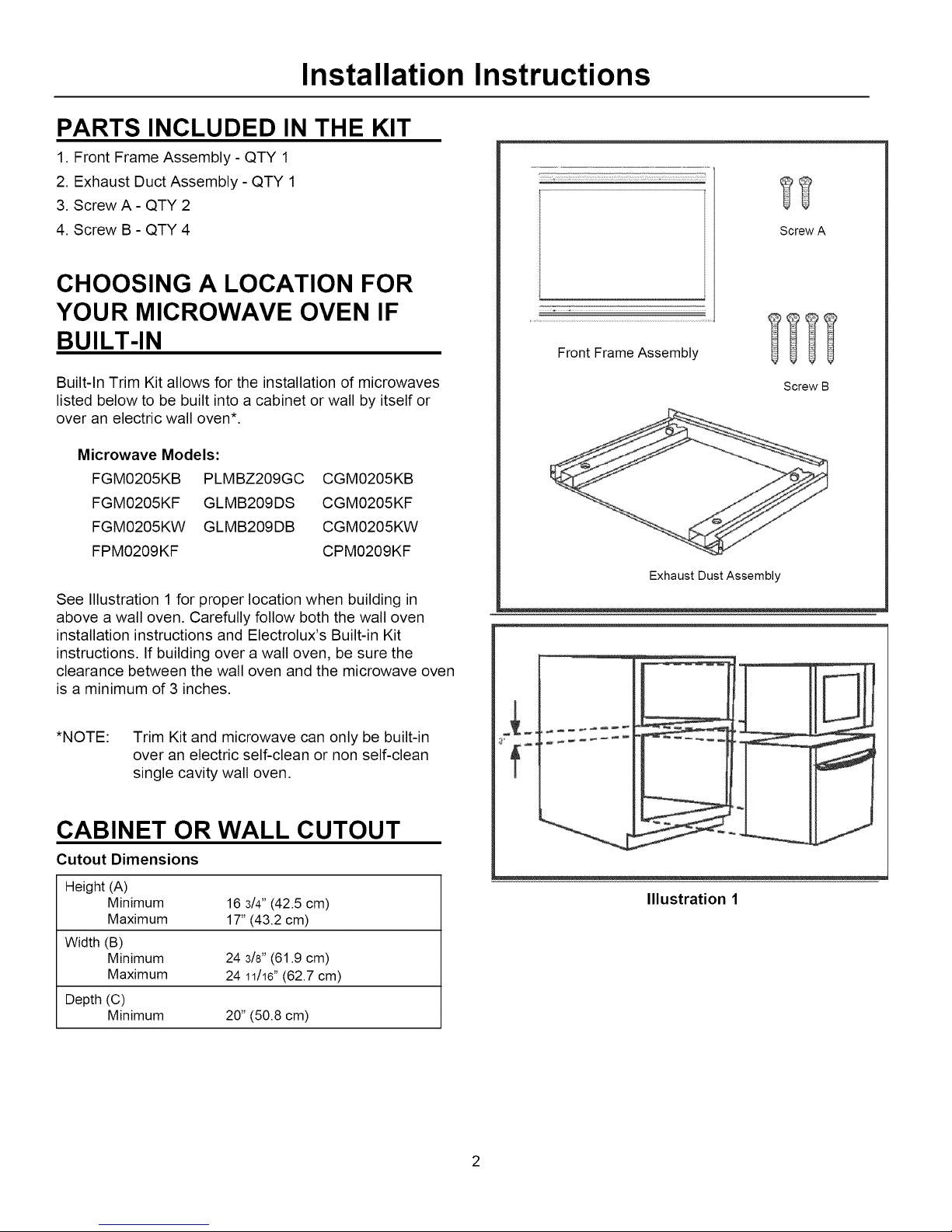
PARTS INCLUDED IN THE KIT
1. Front Frame Assembly - QTY 1
2. Exhaust Duct Assembly - QTY 1
3. Screw A - QTY 2
4. Screw B - QTY 4
CHOOSING A LOCATION FOR
YOUR MICROWAVE OVEN IF
Screw A
= ,
BUILT-IN
Built-In Trim Kit allows for the installation of microwaves
listed below to be built into a cabinet or wall by itself or
over an electric wall oven*.
Microwave Models:
FGM0205KB PLMBZ209GC
FGM0205KF GLMB209DS
FGM0205KW GLMB209DB
FPM0209KF
See Illustration 1for proper location when building in
above a wall oven. Carefully follow both the wall oven
installation instructions and Electrolux's Built-in Kit
instructions. If building over a wall oven, be sure the
clearance between the wall oven and the microwave oven
is a minimum of 3 inches.
*NOTE: Trim Kit and microwave can only be built-in
over an electric self-clean or non self-clean
single cavity wall oven.
CGM0205KB
CGM0205KF
CGM0205KW
CPM0209KF
Front Frame Assembly
Screw B
Exhaust Dust Assembly
CABINET OR WALL CUTOUT
Cutout Dimensions
Height (A)
Minimum 16 3/4"(42.5 cm)
Maximum 17"(43.2 cm)
Width (B)
Minimum 24 3/8"(61.9 cm)
Maximum 24 11/16"(62.7 cm)
Depth (C)
Minimum 20"(50.8 cm)
Illustration 1
Page 3
Installation Instructions
(15.2 cm}
:langes
_crew_
Exhaust Dust
Assembly
Illustration 3
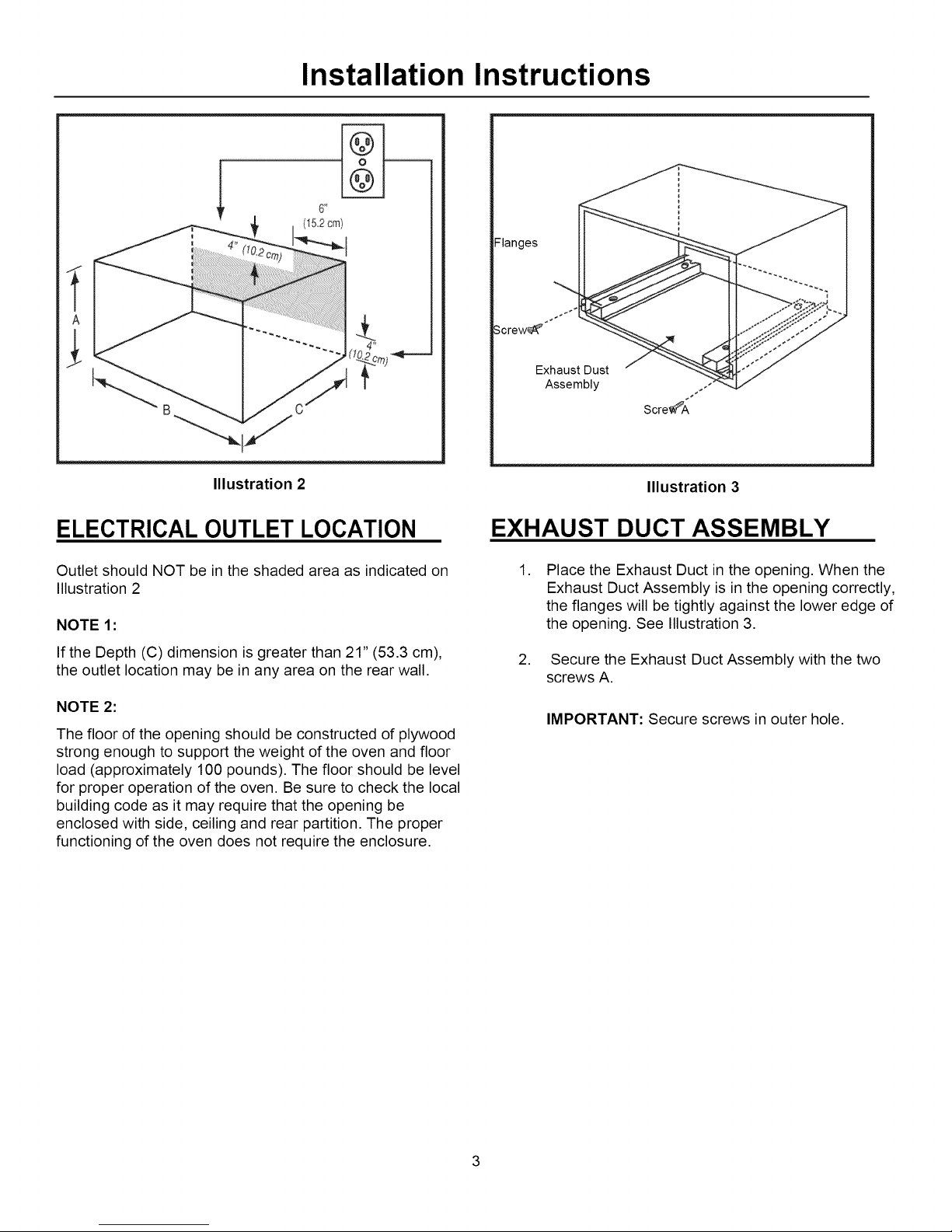
ELECTRICAL OUTLET LOCATION
Outlet should NOT be in the shaded area as indicated on
Illustration 2
NOTE 1:
If the Depth (C) dimension is greater than 21" (53.3 cm),
the outlet location may be in any area on the rear wall.
NOTE 2:
The floor of the opening should be constructed of plywood
strong enough to support the weight of the oven and floor
load (approximately 100 pounds). The floor should be level
for proper operation of the oven. Be sure to check the local
building code as it may require that the opening be
enclosed with side, ceiling and rear partition. The proper
functioning of the oven does not require the enclosure.
EXHAUST DUCT ASSEMBLY
,
Place the Exhaust Duct in the opening. When the
Exhaust Duct Assembly is in the opening correctly,
the flanges will be tightly against the lower edge of
the opening. See Illustration 3.
,
Secure the Exhaust Duct Assembly with the two
screws A.
IMPORTANT: Secure screws in outer hole.
Page 4
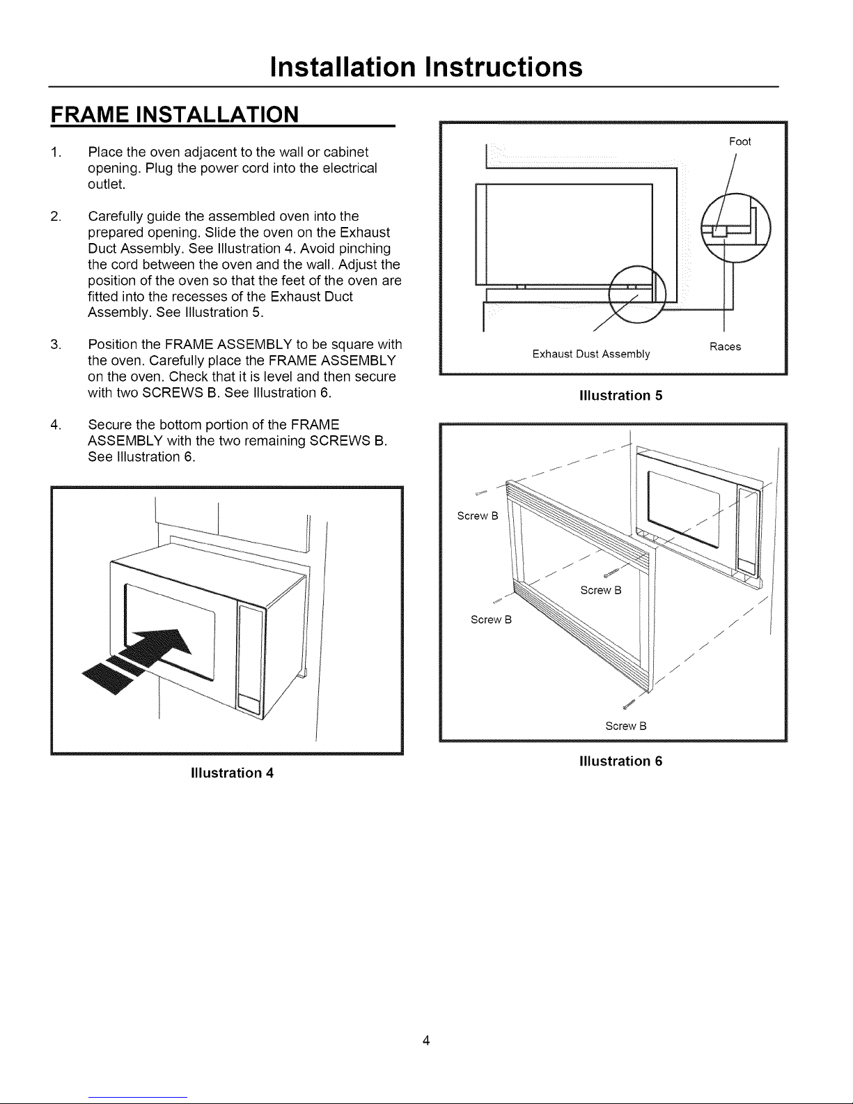
FRAME INSTALLATION
Installation Instructions
,
Place the oven adjacent to the wall or cabinet
opening. Plug the power cord into the electrical
outlet.
,
Carefully guide the assembled oven into the
prepared opening. Slide the oven on the Exhaust
Duct Assembly. See Illustration 4. Avoid pinching
the cord between the oven and the wall. Adjust the
position of the oven so that the feet of the oven are
fitted into the recesses of the Exhaust Duct
Assembly. See Illustration 5.
,
Position the FRAME ASSEMBLY to be square with
the oven. Carefully place the FRAME ASSEMBLY
on the oven. Check that it is level and then secure
with two SCREWS B. See Illustration 6.
,
Secure the bottom portion of the FRAME
ASSEMBLY with the two remaining SCREWS B.
See Illustration 6.
Screw B
Exhaust Dust Assembly
Illustration 5
Foot
Races
Illustration 4
Screw B /
/
Screw B
Illustration 6
/
Page 5

Instructions
d'installation
Ensemble de garniture
d'encastrement
MWTK(P)27K et MWTK(P)30K
AVANT DE COMMENCER
• IMPORTANT- Conserver ces instructions &
I'usage de I'inspecteur local.
• IMPORTANT- Respecter tous les codes et
reglements regissant une telle installation.
• Note destinee & I'installateur - S'assurer de
laisser ces instructions au consommateur.
• Note destinee au consornrnateur - Conserver
ces instructions pour reference ulterieure.
• Niveau de comp_tences - L'installation de
cet appareil exige des comp_tences
_l_mentaires en m_canique et en _lectricit&
POUR VOTRE SECURITE •
AVERTISSEMENT - Avant de commencer
I'installation, couper I'alimentation au tableau de
distribution et verrouiller le disjoncteur principal pour
¢viter que I'alimentation ne soit retablie
accidentellement. Si le disjoncteur ne peut etre
verrouill¢, fixer un dispositif d'avertissement bien
visible, par exemple une etiquette, au tableau de
distribution.
Lisez ces instructions attentivement et au complet :
• L'installateur est responsable de I'installation adequate
de ce produit.
• Toute panne du produit resultant d'une installation
inadequate ne sera pas couverte par la garantie.
• Debrancher le four a micro-ondes avant de proceder
I'installation de cet ensemble.
• Cet ensemble comporte des pieces metalliques, la
prudence est donc de mise Iors de sa manipulation et
de son installation afin d'eviter tout risque de blessure.
• Ne pas enlever du produit les etiquettes
d'avertissement ou les plaques qui y sont apposees
sous risque d'annuler la garantie.
IMPORTANT - LIRE ET SUIVRE
CES INSTRUCTIONS
CET ENSEMBLE DE GARNITURE A
ENCASTREMENT EST DESTINI_ UNIQUEMENT
AUX FOURS A MICRO-ONDES ELECTROLUX
EXIGEANT UNE TELLE GARNITURE.
LA MENTION MWTK(P)27K OU MWTK(P)30K FIGURE
SUR L'€:TIQUETTE DE TENSION DE SERVICE, SUR
LA PAROI LAT#RALE GAUCHE DE LA CAVIT¢: DU
FOUR A MICRO-ONDES.
DES QUESTIONS?
Lesclients des €:tats-Unisdoivent composer le :
1 800 944-9044
Lesclients du Canada doiventcomposer le : 1 800 265-
8352 (pour l'angtais)
1 800 668-4606 poste 8199 (pourle frangais)
Visitez notre site Web & : www.frigidaire.com
LIRE ATTENTIVEMENT.
CONSERVER CES INSTRUCTIONS.
P/N 316495084
JUIN 2009
Page 6

Instructions d'installation
PIECES INCLUSES
1. Cadre avant - QT# 1
2. Conduit d'6vacuation - QT# 1
3. Vis A- QT# 2
4. Vis B - QT# 4
CHOIX DE L'EMPLACEMENT DE
VOTRE FOUR A MICRO-ONDES
Vis A
ENCASTRI_
L'ensemble de garniture d'encastrement est compatible
avec les fours a micro-ondes indiqu6s ci-dessous. Le four
peut etre encastr6 dans une armoire, dans un mur ou au-
dessus d'un four mural 61ectrique.*
ModUles de fours & micro-ondes :
FGM0205KB PLMBZ209GC CGM0205KB
FGM0205KF GLMB209DS CGM0205KF
FGM0205KW GLMB209DB CGM0205KW
FPM0209KF CPM0209KF
Voir I'illustration 1pour I'emplacement ad6quat d'un
appareil encastr6 au-dessus d'un four mural. Suivre avec
soin les instructions d'installation du four mural et celles de
I'appareil encastr6 Electrolux. Si I'appareil est encastr6 au-
dessus d'un four mural, s'assurer qu'il y a un d6gagement
d'au moins 7,6 cm (3 po) entre la paroi du four et le four
micro-ondes.
*REMARQUE : L'ensemble de garniture d'encastrement et
le four a micro-ondes doivent etre installes
uniquement au-dessus d'un four 61ectrique,
mural, simple, autonettoyant ou non.
Cadre avant
Vis B
Conduit d'evacuation
&
OUVERTURE DE L'ARMOIRE OU
DU MUR
Dimensions de I'ouverture
Hauteur (A)
Minimale 16 _ po(42,5 cm)
Maximale 17 po (43,2 cm)
Largeur (B)
Minimale 24 3/8 po (61,9 cm)
Maximale 24 11/16po (62,7 cm)
Profondeur(C)
Minimale 20 po (50,8 cm)
Illustration 1
Page 7

Instructions d'installation
Brides
/is A
Conduit
d'evacuation
Vis A
Illustration 2
EMPLACEMENT DE LA PRISE DE
COURANT
La prise de courant ne doit PAS 6tre placee dans la zone
ombree, comme le montre I'illustration 2.
REMARQUEI:
Si la profondeur (C) de I'ouverture depasse 53,3 cm
(21 po), la prise de courant peut 6tre placee a n'importe
quel endroit sur le mur arriere.
REMARQUE2:
Le plancher de I'ouverture doit etre construit dans un
contreplaque suffisamment solide pour supporter le poids
du four et la surcharge au plancher (environ 45 kg [100 Ib]).
Le plancher doit etre de niveau de maniere a assurer le
bon fonctionnement du four. Verifier votre code du
b&timent local, car il pourrait exiger que des cloisons
(laterales, superieure et inferieure) soient construites dans
la niche. La niche n'a pas besoin d'etre cloisonnee pour
que le four fonctionne correctement..
Illustration 3
MONTAGE DU CONDUIT
D'EVACUATION
,
Placer le conduit d'evacuation dans I'ouverture.
Lorsque le conduit d'evacuation est positionn6
correctement dans I'ouverture, les brides reposent
fermement contre le bord inferieur de I'ouverture.
Voir I'illustration 3.
2. Fixer le conduit d'evacuation a I'aide des deux vis
A.
IMPORTANT :Serrer les vis dans le trou exterieur
Page 8

Instructions d'installation
INSTALLATION DU CADRE
1. Placer le four a c6t6 de I'ouverture pratiquee dans
I'armoire ou lemur. Brancher le cordon
d'alimentation dans la prise de courant.
, Guider avec soin le four assemble dans
I'ouverture pratiquee a cet effet. Glisser le four sur
le conduit d'6vacuation. Voir I'illustration 4. I_viter
que le cordon se coince entre le four et lemur.
R6gler la position du four de maniere ace que les
pieds s'emboftent dans les gorges du conduit
d'6vacuation. Voir I'illustration 5.
,
Positionner le CADRE de maniere ace qu'il soit
d'6querre avec le four. Poser avec soin le CADRE
sur le four. V6rifier qu'il est de niveau et le fixer
avec deux VlS B. Voir I'illustration 6.
,
Fixer la partie inf6rieure du CADRE avec les deux
VlS B qui restent. Voir I'illustration 6.
Pied
Conduit d'evacuation Gorge
Illustration 5
Illustration 4
Vis B
/
/
/
./
/
J
Vis B
Illustration 6
Page 9

Instrucciones
la instalacibn
para
Kit para instalacibn
empotrada
MWTK(P)27K v MWTK(P)30K
ANTES DE COMENZAR
• IMPORTANTE - Guarde estas instrucciones
para su uso por el inspector local.
• IMPORTANTE - Observe todos los cddigos y
reglamentos en vigor.
• Nota para el instalador - Cercidrese de dejar
estas instrucciones con el consulnidor.
• Nota para el consumidor - Guarde estas
instrucciones para futura referencia.
• Nivel de habilidad - La instalacidn de este
artefacto requiere habilidades lnecfinicas y
eldctricas bfisicas.
PARA SU SEGURIDAD:
ADVERTENCIA - Antes de comenzar la
instalaci6n, corte el suministro de electricidad en el
panel de servicio y trabe el medio de desconexi6n
del suministro para evitar que se vuelva a conectar
el suministro electrico accidentalmente. Cuando no
sea posible trabar el medio de desconexidn, f_ieun
dispositivo de advertencia prolninente de lnanera segura,
colno por ejelnplo una etiqueta, al panel de servicio.
Lea estas instrucciones cuidadosamente en su
totalidad.
• La instalaci6n correcta es responsabilidad del
instalador.
• La Garantia no cubre la falla del producto
debida a la instalaci6n incorrecta.
• Desenchufe el homo de microondas antes de
intentar la instalaci6n de este kit.
• Debido a que el kit incluye piezas metNicas, se
debera tener cuidado durante la manipulaci6n y
la instalaci6n para evitar la posibilidad de lesi6n.
• No retire del producto las etiquetas,
advertencias o placas fijadas de manera
permanente. Esto puede invalidar la garantia.
IMPORTANTE - POR FAVOR LEA
Y CUMPLA
ESTE KIT PARA INSTALACION EMPOTRADA
ESTA DISENADO PARA SU USO SOLAMENTE
CON HORNOS DE MICROONDAS DE MARCA
ELECTROLUX QUE ESPECIFIQUEN EL USO DE
UN KIT PARA INSTALACION EMPOTRADA.
MWTK(P)27K o MWTK(P)30K EN LA ETIQUETA DE
VALORES NOMINALES UBICADA EN LA PARED
IZQUIERDA DE LA CAVIDAD DEL HORNO DE
MICROONDAS.
i..TIEN E PREGUNTAS?
Los ctientes en los Estados Unidos pueden llamar al: 1-
800-944-9044
Los ctientes en Canada pueden llamar al: 1-800-265-
8352 (ingtes)
1-800-668-4606 ext.8199 (frances)
Visite nuestro sitio de Internet en: www.frigidaire.com
LEA LAS INSTRUCCliNES DETENIDAMENTE.
GUARDE I=STAS INSTRUCCIONES_
P/N 316495084
JUNIO 2009
Page 10

Instrucciones para la instalaci6n
PARTES QUE SE INCLUYEN EN
EL KIT
1. Conjunto de marco frontal - CANT. 1
2. Conjunto de conducto extractor- CANT. 1
3. Tornillo A - CANT. 2
4. Tornillo B - CANT. 4
Tornillo A
SELECCION DE LA UBICACION
DE SU HORNO DE MICROONDAS
PARA EMPOTRAR
E1kit para instalacidn elnpotrada perlnite instalar los homos de
microondas que se indican a continuacidn elnpotrados en un
gabinete o pared por si solos o sobre un homo eldctrico de
pared*.
Modelos de hornos de microondas:
FGM0205KB PLMBZ209GC CGM0205KB
FGM0205KF GLMB209DS CGM0205KF
FGM0205KW GLMB209DB CGM0205KW
FPM0209KF CPM0209KF
V6ase la ilustraci6n 1 para la ubicaci6n correcta cuando el
homo se va a empotrar sobre un homo de pared. Siga las
instrucciones para la instalaci6n del horno de pared y las
instrucciones del kit para instalaci6n empotrada de
Electrolux cuidadosamente. Si se va a empotrar sobre un
horno de pared, cerci6rese de que la separaci6n vertical
entre el horno de pared y el horno de microondas sea de
por Io menos 3 pulgadas (7.5 cm).
*NOTA: El kit de marco para instalaci6n empotrada y el
homo de microondas s61o podran empotrarse
sobre un homo el6ctrico autolimpiador o no
autolimpiador de pared de una sola cavidad.
= ,
Conjunto de marco frontal
Tornillo B
Conjunto de conducto extractor
""--4
RECORTE EN EL GABINETE O PARED
Dimensiones de la abertura
Altura (A)
Minima 16 _ pulg. (42.5 cm)
Maxima 17 pulg. (43.2 cm)
Ancho (B)
Minimo 24 3/8pulg. (61.9 cm)
Maximo 24 11/16pulg.(62.7 cm)
Profundidad(C)
Minima 20 pulg. (50.8 cm)
Ilustraci6n 1
Page 11

Instrucciones para la instalaci6n
(15.2 cm}
Bridas
rornilloA
4j o-/
Ilustraci6n 2
UBICACION DEL TOMACORRIENTE
El tomacorriente NO debe encontrarse en el area
sombreada que se indica en la Ilustraci6n 2.
NOTA 1:
Si la dimensi6n de la profundidad (C) es de mas de 21
pulg. (53.3 cm), la ubicaci6n del tomacorriente puede estar
en cualquier area de la pared posterior.
NOTA 2:
El piso de la abertura debera estar construido de madera
laminada que sea Io suficientemente fuerte como para
soportar el peso del homo y la carga sobre el piso
(aproximadamente 100 libras). El piso debera estar
nivelado para el funcionamiento correcto del homo.
AsegQrese de consultar el c6digo de construcci6n local, ya
que puede requerir que la abertura est6 encerrada por un
tabique divisorio lateral, superior y posterior. No se
requiere el recinto cerrado para el funcionamiento correcto
del homo.
Conjunto de
conducto extractor
J
Tornillo A
Ilustraci6n 3
CON JUNTO DE CONDUCTO
EXTRACTOR
,
Coloque el conducto extractor en la abertura.
Cuando el conjunto del conducto extractor se ha
colocado en la abertura correctamente, las bridas
quedaran firmemente contra el borde inferior de la
abertura. V6ase la ilustraci6n 3.
2. Asegure el conjunto de conducto extractor con los
dos tornillos A.
IMPORTANTE: Asegure los tornillos en el orificio
exterior.
Page 12

Instrucciones para la instalaci6n
INSTALAClON DEL MARCO
,
Coloque el homo en posici6n adyacente a la
abertura de la pared o del gabinete. Enchufe el
cord6n electrico en el tomacorriente.
, Guie cuidadosamente el homo ensamblado hacia el
interior de la abertura preparada. Deslice el homo
sobre el conjunto de conducto extractor. V6ase la
ilustraci6n 4. Evite comprimir el cord6n entre el
homo y la pared. Ajuste la posici6n del homo, de
manera que las patas del homo encajen en los
rebajes del conjunto del conducto extractor. V6ase
la ilustraci6n 5.
,
Posicione el CON JUNTO DEL MARCO de manera
que encuadre con el homo. Coloque el CON JUNTO
DEL MARCO cuidadosamente sobre el homo.
Verifique que est6 nivelado y asegQrelo con dos
TORNILLOS B. V6ase la ilustraci6n 6.
,
Asegure la porci6n inferior del CON JUNTO DEL
MARCO con los dos TORNILLOS B restantes.
V6ase la ilustraci6n 6.
Tornillo B
Conjunto de conducto extractor
Ilustraci6n 5
Pata
Rebaje
Ilustraci6n 4
Tornillo B /
J
Tornillo B
Ilustraci6n 6
/
 Loading...