

Page 1
INSTALLATION AND SERVICE MUST BE PERFORMED BY
A QUALIFIED INSTALLER.
IMPORTANT: SAVE FOR LOCAL ELECTRICAL INSPECTOR'S USE.
READ AND SAVE THESE INSTRUCTIONS FOR FUTURE REFERENCE.
if the information in this manual is not followed exactly, a fire or explosion may
result causing property damage, personal injury or death.
FORYOUR SAFETY:
-- Do not store or use gasoline or other flammable vapors and liquids in the vicinity of this or any other
appliance.
-- WHATTO DO IFYOU SMELLGAS:
• Do nottrytolightanyappliance.
• Do not touch any electrical switch; do not use any phone in your building.
• Immediately call your gas supplier from a neighbor's phone. Follow the gas supplier's instructions.
• If you cannot reach your gas supplier, call the fire department.
-- Installation and service must be performed by a qualified installer, service agency or the gas supplier.
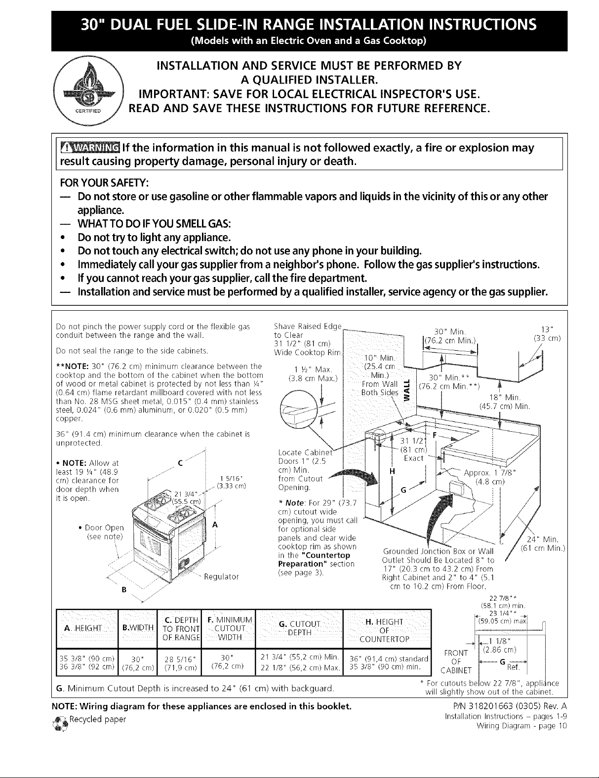
Do not pinch the power supply cord or the flexible gas
conduit between the range and the wall.
Do not seal the range to the side cabinets.
**NOTE: 30" (76.2 cm) minimum clearance between the
cooktop and the bottom of the cabinet when the bottom
of wood or metal cabinet is protected by not less than F4"
(0.64 cm) flame retardant millboard covered with not less
than No. 28 MSG sheet metal, 0.015" (0.4 rnm)stainless
steel, 0.024" (0.6 mrn) aluminum, or 0.020" (0.5 mrn)
copper.
36" (91.4 cm) minimum clearance when the cabinet is
unprotected.
• NOTE: Allow at
least 19 F4" (48.9
crn) clearance for
door depth when
it is open.
• Door Open
z
_" 15/16"
_,21 3/4" _W/ (3.33 cm)
_/55.5 cm/ .......
S
jJJ_i
C ¸
jJ
A
(see
? 2
._ . ....
B
i¸¸ I iL
A HE GHT BIWIDTH
35 318" (90 cm) 30"
36 3/8" (92 cm) (76,2 cm)
G. Minimum Cutout Depth is increased to 24" (61 cm) with backguard.
NOTE: Wiring diagram for these appliances are enclosed in this booklet.
¢-_ Recycled paper
C. DEPTH F.MINIMUM IS cuToUT ' H HEIGHT
TO FRONT CUTOUT ' " _
OF RANGE WDTH DEPTH couN_mToP
28 5/16" 30" 21 3/4" (55,2 crn) Min. 36" (91,4 crn) standard
(71,9 crn) (76,2 cm) 22 1/8" (56,2 cm) Max. 35 3/8" (90 crn) rnin.
g lator
Shave Raised Edge
to Clear 30" Min. 13"
31 1/2" (81 cm) 76.2 crn Min. (33 cm)
Wide Cooktop Rim
1 Y_" Max.
(13.8crn Max.) Min.)
Locate Cabine
Doors 1" (2.5
crn) Min.
from Cutout
Opening.
* Note: For 29" (73.7
crn) cutout wide
opening, you must call
for optional side
panels and clear wide
cooktop rim as shown
in the "Countertop
Preparation" section
(see page 3).
From Wall "q,
Grounded rction Box or Wall
Outlet Should Be Located 8" to
17" (20.3 cm to 43.2 cm) From
Right Cabinet and 2" to 4" (5.1
crn to 10.2 cm) From Floor.
FRONT
CABINET
* For cutouts be ow 22 7/8", appli_ nce
will slightly show out of the cabinet.
18" Min.
(45.7 cm) Min.
24" Min.
(61 crn Min.
22 7/8" *
(58.1 crn)rnin.
__ 23 1/4"*
__1 1/8"
--e
(2.86 crn)
OF
P/N 318201663 (0305) Rev. A
Installation instructions - pages 1-9
Wiring Diagram - page 10
Ref.
Page 2
Important Notes to the Installer
1. Read all instructions contained inthese installation
instructions before installing range.
2. Remove all packing material from the oven
compartments before connecting the gas and electrical
supply to the range.
3. Observe all governing codes and ordinances.
4. Be sure to leavethese instructions with the consumer.
Important Note to the Consumer
Keep these instructions with your owner's guide for future
reference.
IMPORTANT SAFETY
INSTRUCTIONS
Installation of this range must conform with local codes
or, in the absence of local codes, with CAN/CGA-B149.1
and CAN/CGA-B149.2 standards.
This range has been design certified by the American Gas
Association. As with any appliance using gas and
generating heat, there are certain safety precautions you
should follow. You will find them in the Use and Care
Guide, read it carefully.
• Be sure your range is installed and grounded
properly by a qualified installer or service
technician.
• This range must be electrically grounded in
accordance with local codes or, in their absence,
with CSA standard C22.1, Canadian Electrical
Code, Part 1.
• The installation of appliances designed for
manufactured (mobile) home installation must conform
with Manufactured Home Construction and Safety
Standard, title 24CFR, part 3280 [Formerly the Federal
Standard for Mobile Home Construction and Safety,
title 24, HUD (part 280)] or when such standard is not
applicable, the Standard for Manufactured Home
Installation 1982 (Manufactured Home Sites,
Toreduce
• All ranges
can tip.
• Injuryto
personscould
result.
• Install anti-tip
device
packed with
range.
the risk of tipping of the
range, the range must be
secured by properly
installed anti-tip bracket
provided with the range.
To check if the bracket is
installed properly, grasp
the top rear edgge of the
range and carefully tilt it
forward to make sure the
range is anchored.
Communities and Setups), ANSI Z225.1/NFPA 501A-
latest edition, or with CAN/CSA-Z240 MH.
• Make sure the wall coverings around the range
can withstand the heat generated by the range.
• Before installing the range in an area covered
with linoleum or any other synthetic floor
covering, make sure the floor covering can
withstand heat at least 90°F (32.2°C) above room
temperature without shrinking, warping or
discoloring. Do not install the range over carpeting
unless you place an insulating pad or sheet of ¼" (0.6
cm) thick plywood between the range and carpeting.
• Do not obstruct the flow of combustion air at the
oven vent nor around the base or beneath the
lower front panel of the range. Avoid touching the
vent openings or nearby surfaces as they may become
hot while the oven is in operation. This range requires
fresh air for proper burner combustion.
Never leave children alone or
unattended in the area where an appliance is in use.
As children grow, teach them the proper, safe use of all
appliances. Never leave the oven door open when the
range is unattended.
Stepping, leaning or sitting on the
doors or drawers of this range can result in serious
injuries and can also cause damage to the range.
• Do not store items of interest to children in the
cabinets above the range. Children could be seriously
burned climbing on the range to reach items.
• To eliminate the need to reach over the surface
burners, cabinet storage space above the burners
should be avoided.
• Adjust surface burner flame size so it does not
extend beyond the edge of the cooking utensil.
Excessive flame is hazardous.
• Do not use the oven as a storage space. This
creates a potentially hazardous situation.
• Never use your range for warming or heating the
room. Prolonged use of the range without adequate
ventilation can be dangerous.
• Do not store or use gasoline or other flammable
vapors and liquids near this or any other
appliance. Explosions or fires could result.
° In the event of an electrical power outage, the surface
burners can be lit manually. To light a surface burner,
hold a lit match to the burner head and slowly turn the
Surface Control Knob to LITE.Use caution when
lighting surface burners manually.
• Reset all controls to the "off" position after using
a programmable timing operation.
Page 3
Thisapplianceisequippedwith a4-
prong grounding plug for your protection against
shock hazard, and should be plugged directly into a
properly grounded receptacle. Do not cut or remove
the ground prong from this plug.
FOR MODELS WITH SELF-CLEAN FEATURE:
• Remove broiler pan, food and other utensils
before self-cleaning the oven. Wipe up excess
spillage. Follow the precleaning instructions in the Use
and Care Guide.
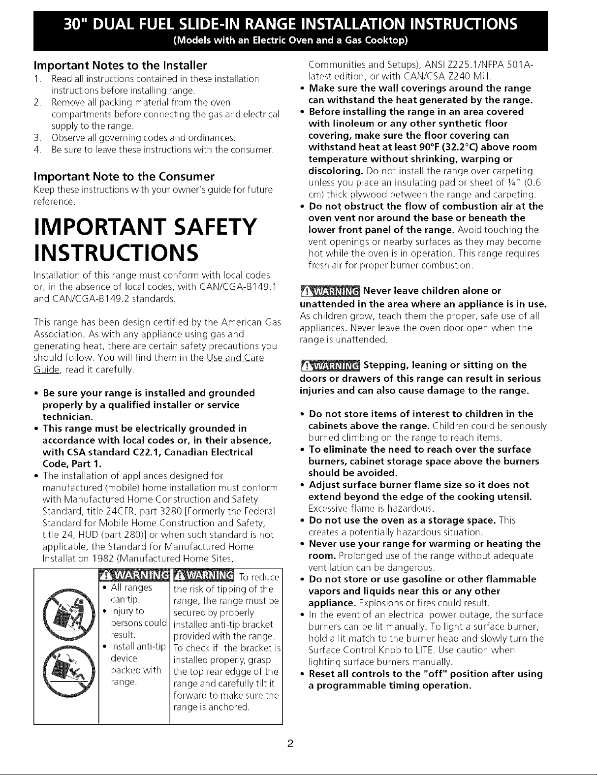
1. Factory Connected Power Supply
Cord
This range is equipped with a factory-connected power
cord (see Figure 1). Cord must be connected to a
grounded 120/240 volt or 120/208 volt range outlet. If
not outlet is available, have one installed by a qualified
electrician.
Canada Style
Figure 1
Cabinet Construction
__ To eliminate the risk of burns or fire by
reaching over heated surface units, do not have cabinet
storage space above the range. If there is cabinet
storage space above range, reduce risk by installing a
range hood that projects horizontally a minimum of 5"
(12.7 cm) beyond the bottom of the cabinet.
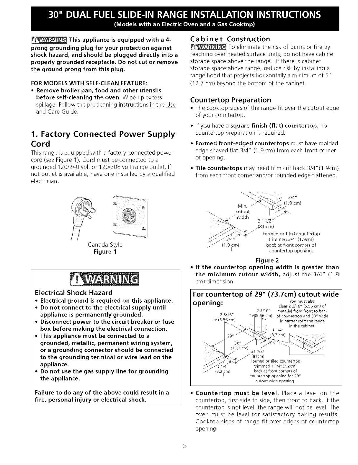
Countertop Preparation
• The cooktop sides of the range fit over the cutout edge
of your countertop.
• If you have a square finish (flat} countertop, no
countertop preparation isrequired.
° Formed front-edged countertops must have molded
edge shaved flat 3/4" (1.9 cm) from each front corner
of opening.
° Tile countertops may need trim cut back 3/4"(1.9cm)
from each front corner and/or rounded edge flattened.
3/4"
Min.
cutout
........width
(1.9 icm) back at front corners of
31 1/2"
.(81 cm)
-'" Formed or tiled countertop
Figure 2
° If the countertop opening width is greater than
the minimum cutout width, adjust the 3/4" (1.9
cm) dimension.
(1.9 cm)
trimmed 3/4" (1.gcm)
countertop opening.
Electrical Shock Hazard
° Electrical ground is required on this appliance.
° Do not connect to the electrical supply until
appliance is permanently grounded.
° Disconnect power to the circuit breaker or fuse
box before making the electrical connection.
° This appliance must be connected to a
grounded, metallic, permanent wiring system,
or a grounding connector should be connected
to the grounding terminal or wire lead on the
appliance.
° Do not use the gas supply line for grounding
the appliance.
Failure to do any of the above could result in a
fire, personal injury or electrical shock.
For countertop of 29" (73.7cm) cutout wide
opening:
2 3/16"
;6 cm)
(3.2 icm)
2 3/16" material from front to back
;6 cm) of countertop and 30" wide
j 1 1/4"
(3.2 cm)
(81cm)
Formed or tiled countertop
trimmed 1 1/4" (3.2cm)
back at front corners of
countertop opening for 29"
cutout wide opening,
You must aUso
dear 2 3/16" (5.56 cm) of
in matter tofit the range
in the cabinet.
° Countertop must be level. Place a level on the
countertop, first side to side, then front to back. If the
countertop is not level, the range will not be level. The
oven must be level for satisfactory baking results.
Cooktop sides of range fit over edges of countertop
opening
Page 4

3. Gas Supply- Installation
When shipped from the factory, this unit isdesigned to
operate on 4"(10,16 cm) water column (1.0 kPa) Natural
gas manifold pressure. A convertible pressure regulator is
connected to the range manifold and MUST be
connected in series with the gas supply line. To access
the regulator, remove the drawer.
When using flexible gas conduit on the range, allow
sufficient slack to pull the range outside the cutout for
cleaning or servicing.
NOTE: Do not allow the flexible conduit to get pinched
between the wall and the range. To visually check,
remove the drawer.
For proper operation, the maximum inlet pressure to
the regulator should be no more than 14"(35,56 cm) of
water column pressure (3.5 kPa).
The inlet pressure to the regulator must be at least 1"
(.25 kPa) greater than the regulator manifold pressure
setting. The regulator is set for 4"(10,16 cm) water
column (1.0 kPa) Natural gas manifold pressure, the inlet
pressure must be at least 5"(12,7 cm) water column
(1.25 kPa) Natural gas. For LP/Propane gas, the regulator
must be set for 10"(25,4 cm) water column (2.5 kPa)
manifold pressure, the inlet pressure must be at least
11 "(27,9 cm) water column (2.75 kPa).
The supply line should be equipped with an approved
shutoff valve (see Figure 3). This valve should be located
in the same room as the range and should be in a
location that allows ease of opening and closing. Do not
block accessto the shutoff valve. The valve is for turning
on or shutting off gas to the appliance.
Open the shutoff valve in the gas supply line. Wait a few
minutes for gas to move through the gas line.
The gas supply between the shutoff valve and the
regulator may be connected by rigid piping or by A.G.A./
C.G.A.-approved flexible metallic union-connected
piping where local codes permit use.
The gas supply piping can be through the side wall of
the right cabinet. The right side cabinet is an ideal
location for the main shutoff valve.
Use pipe-joint compound made for use with Natural and
LP/Propane gas to seal all gas connections. If flexible
connectors are used, be certain connectors are not
kinked.
Leak testing of the appliance shall be conducted
according to the manufacturer's instructions.
Check for leaks. After connecting the range to the gas
supply, check the system for leaks with a manometer. If
a manometer is not available, turn on the gas supply and
use a liquid leak detector at all joints and connections to
check for leaks.
Do not use a flame to check for leaks
from gas connections. Checking for leaks with a flame
may result in a fire or explosion.
All openings in the wall or floor where the range is to be
installed must be sealed.
Tighten all connections if necessary to prevent gas
leakage in the cooktop or supply line.
Check alignment of valves after connecting the
cooktop to the gas supply to be sure the manifold pipe
has not been moved.
Disconnect this range and its individual shutoff
valve from the gas supply piping system during any
pressure testing of that system at test pressures greater
than 1/2 psig (3.5 kPa or 14"(35,56 cm) water column).
Do not make the connection too tight. The regulator is
die cast. Overtightening may crack the regulator
resulting in a gas leak and possible fire or explosion.
Assemble the flexible connector from the gas supply pipe
to the pressure regulator in order: 1- manual shutoff
valve, 2- flare union adapter, 3- flexible connector, 4-
flare union adapter, 5- pressure regulator.
The gas supply line to the shutoff valve should be 1/
2"(1,27 cm) or 3/4"(1,9 cm) solid pipe.
The user must know the location of the main shutoff
valve and have easy access to it.
Isolate the range from the gas supply piping system
by closing its individual manual shutoff valve during any
pressure testing of the gas supply piping system at test
pressures equal to or lessthan 1/2 psig (3.5 kPa or 14"
water column).
4. LP/Propane Gas Conversion
This appliance can be used with Natural gas or LP/
Propane gas. It is shipped from the factory for use with
natural gas.
If you wish to convert your range for use with LP/Propane
gas, use the supplied fixed orifices located in a bag
containing the literature marked "FOR LP/PROPANE GAS
CONVERSION". Follow the instructions packaged with
the orifices.
4
Page 5

PRESSUREREGULATOR
LOCATION
REARWIRE
ACCESS
COVER
RANGE
,_ DOOR
Flexible Appliance Conduit
Install sufficient length of flexible conduit
to allow the range to be pulled
completely out of the cut-out area for
proper servicing (supplied by user). Flare
....... __._ Union
......... Adaptor
through hole provided_
above right rear leveling leg.
Flare
Adaptor
SIDE OF
RANGE
Manual
Sutoff Valve
(supplied by
user) Connect
to Y2"OF3/4''
solid gas
supply pipe
from the wall
or floor.
GAS
SUPPLY
TO
APPLIANCE
Solid Piping Gas Supply
Sutoff
Valve
LP/Propane Gas Conversion (continued)
The conversion must be performed by a qualified service
technician in accordance with the manufacturer's
instructions and all local codes and requirements. Failure
to follow these instructions could result in serious injury
or property damage. The qualified agency performing
this work assumes responsibility for the conversion.
Failure to make the appropriate
conversion can result in personal injury and property
damage.
5. Moving the Appliance for
Servicing and Cleaning
Turn off the range line fuse or circuit breakers at the
main power source, and turn off the manual gas shut-off
valve. Make sure the range is cold. Remove the service
drawer (warmer drawer on some models) and open the
oven door. Lift the range at the front and slide it out of
the cut-out opening without creating undue strain on the
flexible gas conduit. Make sure not to pinch the flexible
gas conduit at the back of the range when replacing the
unit into the cut-out opening. Replace the drawer, close
the door and switch on the electrical power and gas to
the range.
Figure 3
The regulator must be disconnected before moving the
appliance, if the range regulator is connected to rigid
piping. If the range is equipped with a warmer drawer,
the regulator can be accessed through a lateral side
panel. Remove the 2 screws securing the panel, then
remove the panel. Disconnect the regulator from the
piping. Reassemble in reverse order (see Figure 4).
.- warmer
Screw Drawer glide
(do not remove)
s
............Lateral
panel
(RH SIDE)
Figure 4
Page 6

6. Range Installation
When unpacking the range, do not
discard the 4 shipping bolts. These are to be replaced on
the unit for use as leveling legs and height adjustments.
, Installation Without Side Panels
A. The range cooktop overlaps the countertop at
the sides and the range rests on the floor. The
cooktop is31 1/2" (81 cm) wide.
B. Install base cabinets 30" (76.2 cm) apart. Make
sure they are plumb and level before attaching
cooktop. Shave raised countertop edge to clear
31 1/2" (81 cm) wide range top rim.
C. Install cabinet doors 31 " (78.7 cm) min. apart so
as not to interfere with range door opening.
D. Cutout countertop exactly as shown on page 1.
E. A backguard kit can be ordered through your
dealer.
F. Adjust leveling legs so that the underside of the
cooktop is sitting on the countertop.
G. Level the range. The floor where the range
is to be installed must be level (see
Figure 5).
7. Leveling the Range
Level the range and set cooktop height before
installation in the cut-out opening.
1. Install an oven rack in the center of the oven.
2. Place a level on the rack. Take 2 readings with the
level placed diagonally in one direction and then the
other. Level the range, if necessary, by adjusting the
4 leg levelers with a wrench (see Figure 9).
3. Taking care to not damage the countertop, slide
range into cut-out opening and double check for
levelness. If the range is not level, pull unit out and
readjust leveling legs, or make sure floor is level.
,
Installation For 29" Cutout Wide Opening
A. You must replace the actual side trims by new
and smaller side trims. These new side trimscan
be ordered through a Service Center.
B. Follow instructions supply with your new side
trims to replace the actual side trims by the new
ones.
C. Check if the countertop is prepared for 29"
cutout wide opening in "Countertop
Preparation" section at page 3.
D. Install range as in the "Installation Without
Side Panels" section.
3. Installation With Backguard
The cutout depth of (21 3/4" (55.2 cm)Min., 22 1/8"
(56.2cm) Max.) needs to be increased to 24" (61 cm)
when installing a backguard.
4. Installation With End Panel
A End Panel kit can be ordered through a Service
Center.
5. Installation With Side Panels
A Side Panels kit can be ordered through a Service
Center.
A. Install cabinet doors 31 " (78.7 cm) min. apart so
as not to interfere with range door opening.
B. A backguard kit can be ordered through a
Service Center.
C. An end panel kit can be ordered through a
Service Center.Center.
Figure 5
6
Page 7

8. Check Operation
Refer to the Owner's Guide packaged with the range for
operating instructions and for care and cleaning of your
range.
Do not touch the elements or burners.
They may be hot enough to cause burns.
2. Turn on Electrical Power and Open Main
Shutoff Gas Valve
,
Check the Igniters
Operation of electric igniters should be checked
after range and supply line connectors have been
carefully checked for leaks and range has been
connected to electric power.
Remove all packaging from the oven before testing.
1. Install Burner Bases and Burner Caps
This range is equipped with sealed burners as shown
(see Figure 6).
Burner Cap_
Burner Base-- d
Burner Pan
Gas Opening
Electrode
Figure 6
A.
Unpack burner bases and burner caps.
B.
Place burner bases over each gas opening.
C.
Make sure the burner is properly aligned and
leveled. Place burner caps over appropriate
burner bases.
To check for proper lighting:
A. Push in and turn a surface burner knob to the
LITEposition. You will hear the igniter sparking.
B. The surface burner should light when gas is
available to the top burner. Eachburner should
light within four (4) seconds in normal operation
after air has been purged from supply lines.
Visually check that burner has lit.
C. Once the burner lights, the control knob should
be rotated out of the LITEposition.
There are separate ignition devices for each burner.
Try each knob separately until all burner valves have
been checked.
,
Adjust the "LOW" Setting of Surface Burner
Valves (see Figure 7)
A. Push in and turn each control to LITEuntil
burner ignites.
B. Quickly turn knob to LOWEST POSITION.
C. If burner goes out, readjust valve asfollows:
Reset control to OFF. Remove the surface burner
control knob, insert a thin-bladed screw driver
into the hollow valve stem and engage the
slotted screw inside. Flame size can be
increased or decreased with the turn of the
screw. Adjust flame until you can quickly turn
knob from LITEto LOWESTPOSITION without
extinguishing the flame. Flame should be as
small as possible without going out.
NOTE: There are no burner adjustments necessary on
this range.
Figure 7 _%
Page 8

5.Operationof OvenElements
The oven isequipped with an electronic oven control.
Each of the functions has been factory checked before
shipping. However, it is suggested that you verify the
operation of the electronic oven controls once more. Refer
to the Owner's Guide for operation. Follow the instructions
for the Clock, Timer, Bake, Broil, Convection (some
models) and Clean functions.
Bake-After setting the oven to 350% (177°C) for baking,
the lower element in the oven should become red.
Broil-When the oven is set to BROIL, the upper element
in the oven should become red.
Model and Serial Number Location
The serial plate is located on the oven front frame
behind the oven door (somemodel_ or behind the
drawer (some models).
When ordering parts for or making inquiries about your
range, always be sure to include the model and serial
numbers and a lot number or letter from the serial plate
on your range.
Your serial plate also tells you the rating of the burners,
the type of fuel and the pressure the range was adjusted
for when it left the factory.
Clean-When the oven is set for a self-cleaning cycle, the
upper element should become red during the preheat
portion of the cycle. After reaching the self-cleaning
temperature, the lower element will become red.
Convection (some models)-When the oven is set to
CONV. BAKE/ROAST at 350% (177°C), both elements
cycle on and off alternately and the convection fan will
turn. The convection fan will stop turning when the oven
door isopened during convection baking or roasting.
Warmer Drawer (some models)-Set the control knob
to HI and check to see the drawer is heating.
When All Hookups are Complete
Make sure all controls are left in the OFFposition.
Make sure the flow of combustion and ventilation air to
the range isunobstructed.
Before You Call for Service
Read the Avoid Service Checklist and operating
instructions in your Owner's Guide. It may save you time
and expense. The list includes common occurrences that
are not the result of defective workmanship or materials
in this appliance.
Refer to the warranty and service information in your
Owner's Guide for our phone number and address.
Please call or write if you have inquiries about your
range product and/or need to order parts.
Page 9

9. Important Safety Warning
To reduce the risk of tipping of the range, the range
must be secured to the floor by properly installed anti-tip
brackets and screws packed with the range. Those parts
are located in a plastic bag in the oven. Failure to install
the anti-tip brackets will allow the range to tip over if
excessive weight is placed on an open door or if a child
climbs upon it. Serious injury might result from spilled
hot liquids or from the range itself.
Follow the instructions below to install the anti-tip
brackets.
If range is ever moved to a different location, the anti-tip
brackets must also be moved and installed with the
range. To check for proper installation, see step 5.
Tools Required:
5/16" (0,79 cm) Nutdriver or Flat Head Screwdriver
Adjustable Wrench
Electric Drill
3/16"(0,48 cm) Diameter Drill Bit
3/16"(0,48 cm) Diameter Masonry Drill Bit (if installing in
concrete)
Anti-Tip Brackets Installation Instructions
Brackets attach to the floor at the back of the range to
hold both rear leg levelers. When fastening to the floor,
be sure that screws do not penetrate electrical wiring or
plumbing. The screws provided will work in either wood
or concrete.
1. Unfold paper template and place it flat on the floor
with the back and side edges positioned exactly
where the back and sides of range will be located
when installed. (Usethe diagram below to locate
brackets if template is not available.)
2. Mark on the floor the location of the 4 mounting
holes shown on the template. For easier installation,
3/16" (0.5 cm) diameter pilot holes 1/2" (1.3 cm)
deep can be drilled into the floor.
3. Remove template and place brackets on floor with
turned up flange to the front. Line up holes in
brackets with marks on floor and attach with 4
screws provided. Brackets must be secured to solid
floor. If attaching to concrete floor, first drill 3/16"
(0.5 cm) dia. pilot holes using a masonry drill bit.
4. Level range if necessary, by adjusting 4 leg levelers
with wrench (see Figure 9). A minimum clearance of
1/8" (0.8 cm) is required between the bottom of the
range and the rear leg levelers to allow room for the
anti-tip brackets.
5. Slide range into place making sure rear legs are
trapped by ends of brackets. Range may need to be
shifted slightly to one side as it is being pushed back
to allow rear legs to align with brackets. Grasp the
top rear edge of the range and carefully attempt to
tilt it forward to make sure range is properly
anchored.
Figure 8
Figure 9
Back
Page 10

COOKTOP C 1RCUt T/C 1RCU 1TO DE PLANCHA DE COCI NAR/
C l RCU 1T TABLE CUt BSON
} ION V
tNT N_ RU_,<C
FC_J BLTa% R ]GNI]E R ! INTER /ALUM
D_EHr_OC_ DE ENSENDIOO SUPERICq OAR
JUG I " _,1 H_t_AC,
R /0 R ?0
IZOJE_@O
OVEN CtRCUtT!CtRCU_TO DE HORNO/
CIRCUIT DU FOUR
L2
Bg'dO_E D'ALLUVAGE BR CEUR
TOP 8L_'_ER IG ITER
OUEKAJ_R DE E £NDI 0 bUPERJUR
¢YDUGJ 'ALLU_:N:L 8CLUR R 10
8
ION] FER ',IODULE BOr, RO
N _> 0LOC C0NNEC {0N A/LUMEUR
MINUTERIE I ...........
_Z ,_ARHER ZO',E ELE ENT
0 SCONNECT P0_ER BEFORE 5ERV C NG UNiT
DESCONECTE LA ENERGIA ANTES ]E REALIZAR
EL f!ANTENII!IENT0 DL LECTRODOMESTICB
COUPER LE COURA_ AV_NT D'EFFECTUER
CUADRO DE MODULO DE ENCENO_DO
ELEMEN 00E CA EN ADOR
ELEPEN RECHAUD
,AT _
LHIT R Pi[0T I GpT
L r ITADOR LP, PPY, Rf_ PLOTO
L MITEUR [AMP I[M)IN
! 0 20 I 50 ,1:_2 ] _ ......... _ 0 TIONAL
R 10 R /0
R 10
T NC rRASERO
O ;# £HO
INTE AL_
POWER CORO
pARR TRAN_2$RTE
BE FUFRZA
CA@IE
O'ALiMENTATiON
ELEMENT 80! VECl ION
_ 0Ir/00 04 0 _10 _ RELAIS lENT L£TEUR
C0NVECCION/MOTEUR VENT LATEUR CONVECT ON COOL JNG FAN/VENrI[,SOOR 0[ ENPR AMIENT0/
R4 .
LACH MO OR/NOTOR DE CERROJO/
M0 UR VE ?ROU
6Y d _>>B_<__ 8,< a
N LRR_ER I EHENT/EI EMENTO DE Ca ENTA, OR/
_*_2 _ _CONN 8 EU_ 80R/OU C_ FACULTATIF / pIINUTERIE 10 Ml IqM/T[£IM O[ .IM[ O JO/ MINUTERIE
_.::521
3 I 22
3 3 2 /
3173
3 I 7
i
"1 _ _A_c) _ MP_RTANT/ MP_RTA.T_. co_,;_r__E .US 0EUSE0_0r._CONNECT0 S O CONDU_,,mS
I I I ....................... _LANBRE DE COBRE DE_E OE SERT LIZADO PAR_ A CONNEXION
1 _ / EHPAI H RACCORDE ENT AU CABLE 0E L APPAREIL
I
/
I CO ECO@E LE I _/v A
I
I I " "/> .... / l "OFF AC/,P£DO PUERT£ DE HORNO AB]ER /_ Y NO CERRPOA
X
I
i
--/{
)> _ PI5- A -
_ _ THM 0, S0E t iMIT
I C0NK;CTELR _ " _ _"_ EL C RCU TO ESTA LLUSTRAOO CON 0OOS L00 CONTROLES A
_ _ ,/_'k/ ....... E OCHEH ELECTRIOUE IND LIE OUE LES _OMMANDES
O0 , _,
_ _ ,%_ 'i LEOE 0/L EN0 ONT A 'ARR T" QU A PORT ST FER ET NON
TMER
CONTROL ELE _ENT RECHAUD
M[NUTER]
L/_/ CONNECf01 U iLISE/ UN CALE AVEC CONOUC EUR0 N CUIVR; FOUR LE
/' CONNECTEUR NOTE/NOTA;
BK _ _j U _ L ,_
IF'N EL ' ELE
VENTILA EdR REFRO D!SSEPIENT IBRa !
PI/ 8
YoDoULS YLEuLJl ,....-......... ....-, _3' _0Z C09 i P<L\'. U
 Loading...