

Page 1
Installation Instructions
Installation
BEFORE YOU BEGIN
IMPORTANT – Save these instructions
for local inspector's use.
IMPORTANT – Observe all governing
codes and coordinates.
Note to Installer – Be sure to leave
these instructions with the Consumer.
Note to Consumer – Keep these
instructions for future reference.
Skill level - Installation of this appliance
requires basic mechanical and electrical
skills
FOR YOUR SAFETY:
WARNING – Before beginning the installation,
switch power off at service panel and lock the
service disconnecting means to prevent power from
being switched on accidentally. When the service
disconnecting means cannot be locked, securely
fasten a prominent warning device, such as a tag, to
the service panel.
Built-in Trim Kit
MWTK(P)27K and MWTK(P)30K
Read these instructions completely and carefully.
Proper installation is the responsibility of the
installer.
Product failure due to improper installation is
not covered under the Warranty.
Unplug the microwave oven before
attempting installation of this kit.
Because the kit includes metal parts, caution
should be used in handling and installation to
avoid the possibility of injury.
Do not remove permanently affixed labels,
warnings, or plates from the product. This
may void the warranty.
IMPORTANT - PLEASE READ
AND FOLLOW
THIS BUILT-IN KIT IS DESIGNED FOR USE
ONLY WITH ELECTROLUX MICROWAVE
OVENS SPECIFYING BUILT-IN KIT
MWTK(P)27K OR MWTK(P)30K ON THE RATING
LABEL ON THE LEFT SIDE WALL OF THE
MICROWAVE OVEN CAVITY.
QUESTIONS?
For customers in the United States call: 1-800-944-9044
For customers in Canada call: 1-800-265-8352 (English)
1-800-668-4606 ext.8199 (French)
Visit our Website at: www.frigidaire.com
READ CAREFULLY.
KEEP THESE INSTRUCTIONS.
PN316495084
SEPT 2009
1
Page 2
Installation Instructions
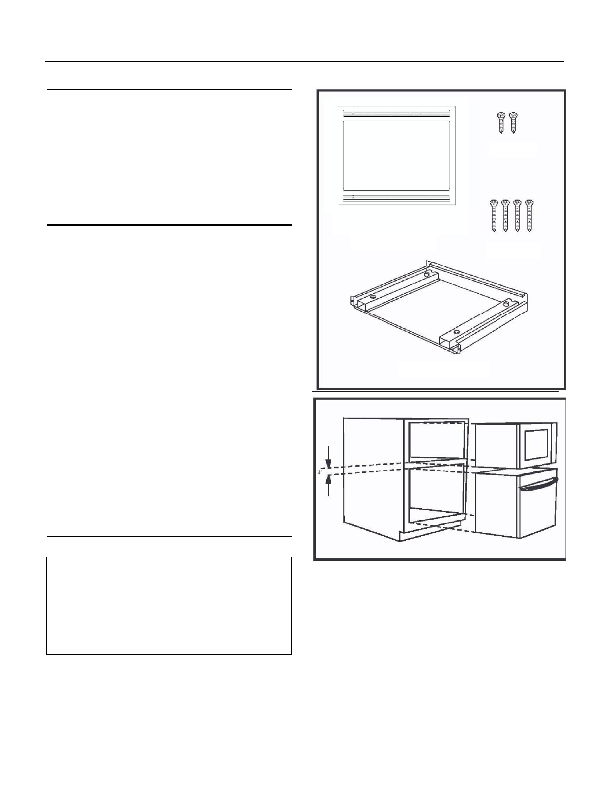
PARTS INCLUDED IN THE KIT
1. Front Frame Assembly - QTY 1
2. Exhaust Duct Assembly - QTY 1
3. Screw A - QTY 2
4. Screw B - QTY 4
CHOOSING A LOCATION FOR
YOUR MICROWAVE OVEN IF
Screw A
BUILT-I
Built-In Trim Kit allows for the installation of microwaves
listed below to be built into a cabinet or wall by itself or
over an electric wall oven*.
Microwave Models:
FGM0205KB PLMBZ209GC CGM0205KB
FGM0205KF GLMB209DS CGM0205KF
FGM0205KW GLMB209DB CGM0205KW
FPM0209KF CPM0209KF
See Illustration 1 for proper location when building in
above a wall oven. Carefully follow both the wall oven
installation instructions and Electrolux’s Built-in Kit
instructions. If building over a wall oven, be sure the
clearance between the wall oven and the microwave
oven is a minimum of 3 inches.
*NOTE: Trim Kit and microwave can only be built-in
N
over an electric self-clean or non self-clean
single cavity wall oven.
Front Frame Assembly
Exhaust Dust Assembly
Screw
B
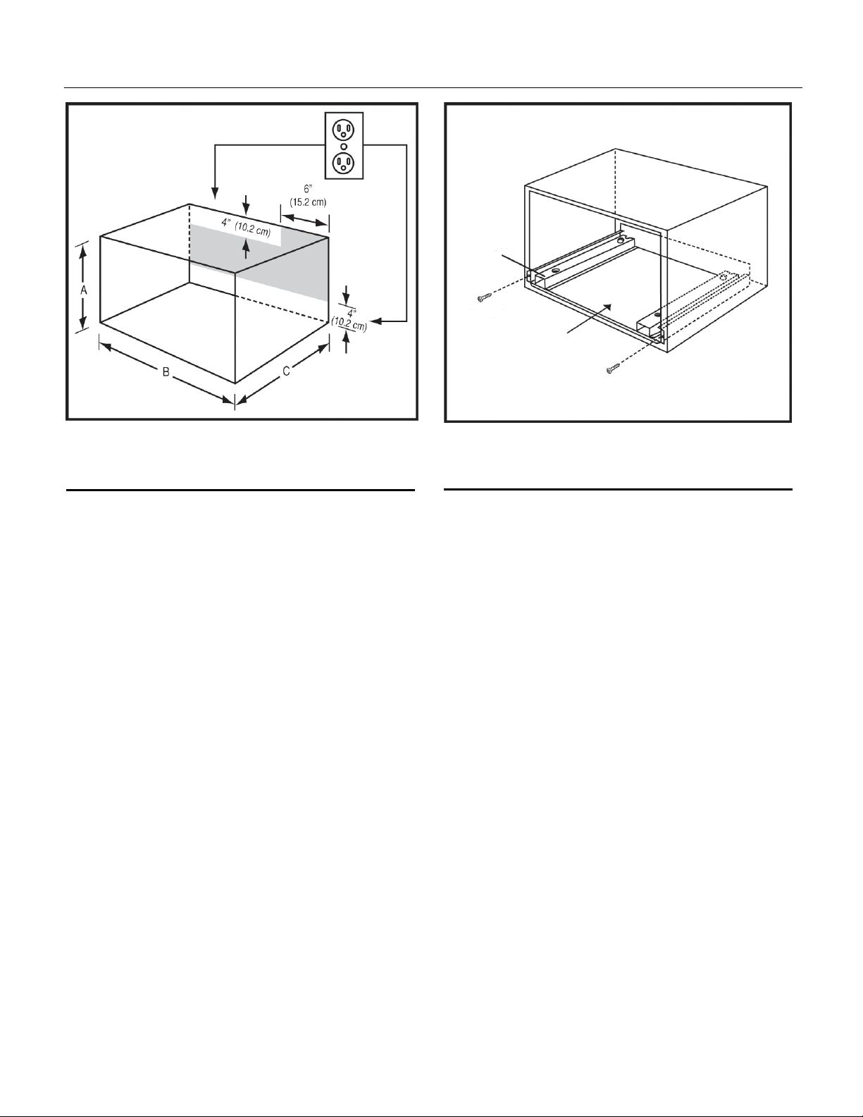
CABINET OR WALL CUTOUT
Cutout Dimensions
Height (A)
Minimum
Maximum
Width (B)
Minimum
Maximum
Depth (C)
Minimum
16
3/4” (42.5 cm)
17” (43.2 cm)
24
3/4” (62.9 cm)
25” (63.5 cm)
20” (50.8 cm)
2
Illustration 1
Page 3
Installation Instructions
Flanges
Screw A
Exhaust Dust
Assembly
Screw
A
Illustration 2
ELECTRICAL OUTLET LOCATION
Outlet should NOT be in the shaded area as indicated
on Illustration 2
NOTE 1:
If the Depth (C) dimension is greater than 21” (53.3 cm),
the outlet location may be in any area on the rear wall.
NOTE 2:
The floor of the opening should be constructed of
plywood strong enough to support the weight of the
oven and floor load (approximately 100 pounds). The
floor should be level for proper operation of the oven. Be
sure to check the local building code as it may require
that the opening be enclosed with side, ceiling and rear
partition. The proper functioning of the oven does not
require the enclosure.
Illustration 3
EXHAUST DUCT ASSEMBLY
1. Place the Exhaust Duct in the opening. When
the Exhaust Duct Assembly is in the opening
correctly, the flanges will be tightly against the
lower edge of the opening. See Illustration 3.
2. Secure the Exhaust Duct Assembly with the
two screws A.
IMPORTANT: Secure screws in outer hole.
3
Page 4
Installation Instructions
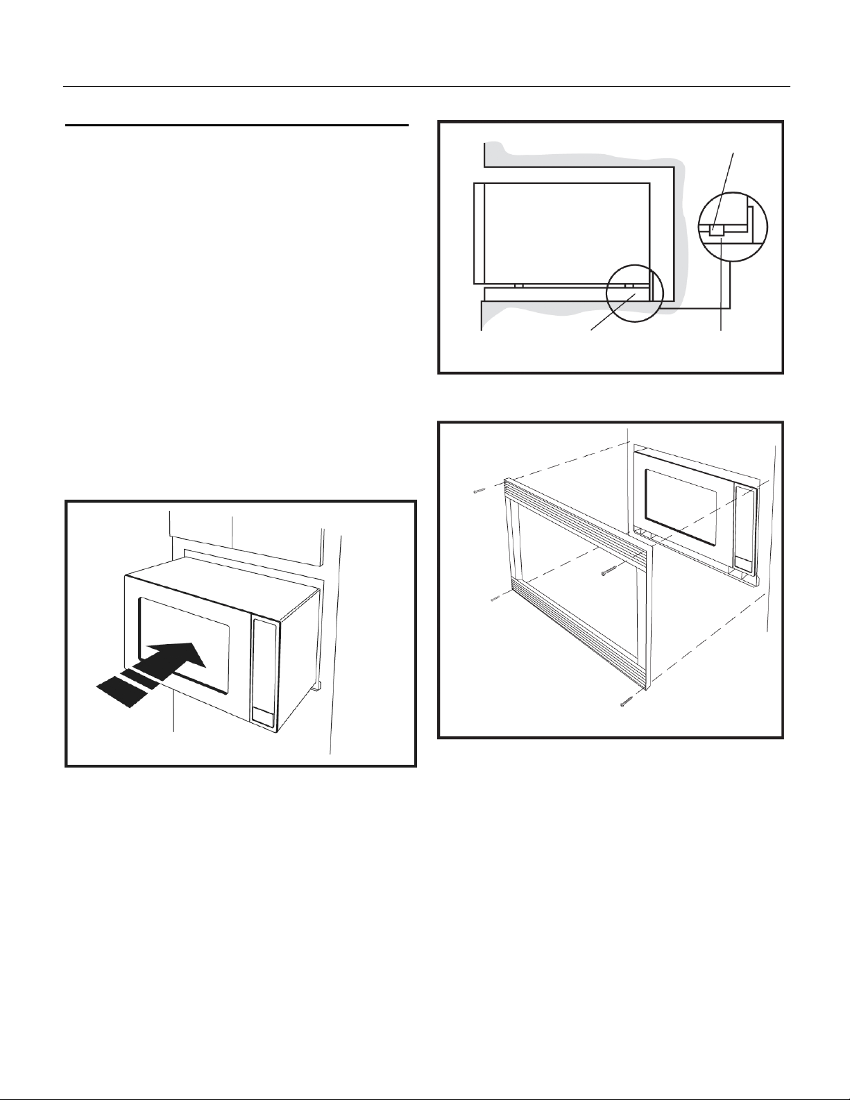
FRAME INSTALLATION
1. Place the oven adjacent to the wall or cabinet
opening. Plug the power cord into the electrical
outlet.
2. Carefully guide the assembled oven into the
prepared opening. Slide the oven on the Exhaust
Duct Assembly. See Illustration 4. Avoid pinching
the cord between the oven and the wall. Adjust
the position of the oven so that the feet of the
oven are fitted into the recesses of the Exhaust
Duct Assembly. See Illustration 5.
3. Position the FRAME ASSEMBLY to be square
with the oven. Carefully place the FRAME
ASSEMBLY on the oven. Check that it is level and
then secure with two SCREWS B. See Illustration
6.
4.
Secure the bottom portion of the FRAME
ASSEMBLY with the two remaining SCREWS B.
See Illustration 6.
Foot
Exhaust Dust Assembly
Illustration 5
Races
Illustration 4
B
Screw
Screw B
Screw B
Screw B
Illustration 6
4
Page 5

Instructions d'installation
Instructions
'
AVANT DE COMMENCER
IMPORTANT – Conserver ces instructions à
l’usage de l’inspecteur local.
IMPORTANT – Respecter tous les codes et
règlements régissant une telle installation.
Note destinée à l’installateur – S’assurer de
laisser ces instructions au consommat eur.
Note destinée au consommateur – Conserver
ces instructions pour référence ultérieure.
Niveau de compétences – L’installation de
cet appareil exige des compétences
élémentaires en mécanique et en électricité.
POUR VOTRE SÉCURITÉ :
AVERTISSEMENT – Avant de commencer
l’installation, couper l’alimentation au tableau de
distribution et verrouiller le disjoncteur principal pour
éviter que l’alimentation ne soit rétablie
accidentellement. Si le disjoncteur ne peut être
verrouillé, fixer un dispositif d’avertissement bien
visible, par exemple une étiquette, au tableau de
distribution.
.
Ensemble de garniture
d'encastrement
MWTK(P)27K et MWTK(P)30K
Lisez ces instructions attentivement et au complet :
L’installateur est responsable de l’installation adéquate
de ce produit.
Toute panne du produit résultant d’une installation
inadéquate ne sera pas couverte par la garantie.
Débrancher le four à micro-ondes avant de procéder à
l’installation de cet ensemble.
Cet ensemble comporte des pièces métalliques, la
prudence est donc de mise lors de sa manipulation et
de son installation afin d’éviter tout risque de blessure.
Ne pas enlever du produit les étiquettes
d’avertissement ou les plaques qui y sont apposées
sous risque d’annuler la garantie.
IMPORTANT - LIRE ET SUIVRE
CES INSTRUCTIONS
CET ENSEMBLE DE GARNITURE À
ENCASTREMENT EST DESTINÉ UNIQUEMENT
AUX FOURS À MICRO-ONDES ELECTROLUX
EXIGEANT UNE TELLE GARNITURE.
LA MENTION MWTK(P)27K OU MWTK(P)30K FIGURE
SUR L’ÉTIQUETTE DE TENSION DE SERVICE, SUR
LA PAROI LATÉRALE GAUCHE DE LA CAVITÉ DU
FOUR À MICRO-ONDES.
DES QUESTIONS?
Les clients des États-Unis doivent composer le :
1 800 944-9044
Les clients du Canada doivent composer le : 1 800 2658352 (pour l’anglais)
1 800 668-4606 poste 8199 (pour le français)
Visitez notre site Web à : www.frigidaire.com
LIRE ATTENTIVEMENT.
CONSERVER CES INSTRUCTIONS.
1
PN316495084
SEPT 2009
Page 6

Instructions d'installation
PIÈCES INCLUSES
1. Cadre avant – QTÉ 1
2. Conduit d’évacuation – QTÉ 1
3. Vis A – QTÉ 2
4. Vis B – QTÉ 4
CHOIX DE L'EMPLACEMENT DE
VOTRE FOUR À MICRO-ONDES
Vis A
ENCASTRÉ
L’ensemble de garniture d’encastrement est compatible
avec les fours à micro-ondes indiqués ci-dessous. Le four
peut être encastré dans une armoire, dans un mur ou audessus d’un four mural électrique.*
Modèles de fours à micro-ondes :
FGM0205KB PLMBZ209GC CGM0205KB
FGM0205KF GLMB209DS CGM0205KF
FGM0205KW GLMB209DB CGM0205KW
FPM0209KF CPM0209KF
Voir l’illustration 1 pour l’emplacement adéquat d’un
appareil encastré au-dessus d’un four mural. Suivre avec
soin les instructions d’installation du four mural et celles de
l’appareil encastré Electrolux. Si l’appareil est encastré audessus d’un four mural, s’assurer qu’il y a un dégagement
d’au moins 7,6 cm (3 po) entre la paroi du four et le four à
micro-ondes.
*REMARQUE : L’ensemble de garniture d’encastrement et
le four à micro-ondes doivent être installés
uniquement au-dessus d’un four électrique,
mural, simple, autonettoyant ou non.
OUVERTURE DE L'ARMOIRE OU
DU MUR
Dimensions de l'ouverture
Hauteur (A)
Minimale
Maximale
Largeur (B)
Minimale
Maximale
Profondeur (C)
Minimale
16
¾ po (42,5 cm)
17 po (43,2 cm)
24 3/4 po (62,9 cm)
25 po (63,5 cm)
20 po (50,8 cm)
Cadre avant
Vis B
Conduit d’évacuation
Illustration 1
2
Page 7

Instructions d'installation
Brides
Vis A
Conduit
d’évacuation
Vis A
Illustration 2
EMPLACEMENT DE LA PRISE DE
COURANT
La prise de courant ne doit PAS être placée dans la zone
ombrée, comme le montre l’illustration 2.
REMARQUE 1 :
Si la profondeur (C) de l’ouverture dépasse 53,3 cm
(21 po), la prise de courant peut être placée à n’importe
quel endroit sur le mur arrière.
REMARQUE 2 :
Le plancher de l’ouverture doit être construit dans un
contreplaqué suffisamment solide pour supporter le poids
du four et la surcharge au plancher (environ 45 kg [100 lb]).
Le plancher doit être de niveau de manière à assurer le
bon fonctionnement du four. Vérifier votre code du
bâtiment local, car il pourrait exiger que des cloisons
(latérales, supérieure et inférieure) soient construites dans
la niche. La niche n’a pas besoin d’être cloisonnée pour
que le four fonctionne correctement..
Illustration 3
MONTAGE DU CONDUIT
D'ÉVACUATION
1. Placer le conduit d’évacuation dans l’ouverture.
Lorsque le conduit d’évacuation est positionné
correctement dans l’ouverture, les brides reposent
fermement contre le bord inférieur de l’ouverture.
Voir l’illustration 3.
2. Fixer le conduit d’évacuation à l’aide des deux vis
A.
IMPORTANT : Serrer les vis dans le trou extérieur
3
Page 8

Instructions d'installation
INSTALLATION DU CADRE
1. Placer le four à côté de l’ouverture pratiquée dans
l’armoire ou le mur. Brancher le cordon
d’alimentation dans la prise de courant.
2.
Guider avec soin le four assemblé dans
l’ouverture pratiquée à cet effet. Glisser le four sur
le conduit d’évacuation. Voir l’illustration 4. Éviter
que le cordon se coince entre le four et le mur.
Régler la position du four de manière à ce que les
pieds s’emboîtent dans les gorges du conduit
d’évacuation. Voir l’illustration 5.
3. Positionner le CADRE de manière à ce qu’il soit
d’équerre avec le four. Poser avec soin le CADRE
sur le four. Vérifier qu’il est de niveau et le fixer
avec deux VIS B. Voir l’illustration 6.
4. Fixer la partie inférieure du CADRE avec les deux
VIS B qui restent. Voir l’illustration 6.
Pied
Gorg
Conduit d’évacuation
Illustration 5
e
Vis B
Illustration 4
Vis B
Vis B
Vis B
Illustration 6
4
Page 9

Instrucciones para
la instalación
Instrucciones para la instalación
ANTES DE COMENZAR
IMPORTANTE – Guarde estas instrucciones
para su uso por el inspector local.
IMPORTANTE - Observe todos los códigos y
reglamentos en vigor.
Nota para el instalador - Cerciórese de dejar
estas instrucciones con el consumidor.
Nota para el consumidor – Guarde estas
instrucciones para futura referencia.
Nivel de habilidad – La instalación de este
artefacto requiere habilidades mecánicas y
eléctricas básicas.
PARA SU SEGURIDAD:
ADVERTENCIA – Antes de comenzar la
instalación, corte el suministro de electricidad en el
panel de servicio y trabe el medio de desconexión
del suministro para evitar que se vuelva a conectar
el suministro eléctrico accidentalmente. Cuando no
sea posible trabar el medio de desconexión, fije un
dispositivo de advertencia prominente de manera segura,
como por ejemplo una etiqueta, al panel de servicio.
Kit para instalación
empotrada
MWTK(P)27K y MWTK(P)30K
Lea es
totalidad.
tas instrucciones cuidadosamente en su
La instalación correcta es responsabilidad del
instalador.
La Garantía no cubre la falla del producto
debida a la instalación incorrecta.
Desenchufe el horno de microondas antes de
intentar la instalación de este kit.
Debido a que el kit incluye piezas metálicas, se
deberá tener cuidado durante la manipulación y
la instalación para evitar la posibilidad de lesión.
No retire del producto las etiquetas,
advertencias o placas fijadas de manera
permanente. Esto puede invalidar la garantía.
IMPORTANTE - POR FAVOR LEA
Y CUMPLA
ESTE KIT PARA INSTALACIÓN EMPOTRADA
ESTÁ DISEÑADO PARA SU USO SOLAMENTE
CON HORNOS DE MICROONDAS DE MARCA
ELECTROLUX QUE ESPECIFIQUEN EL USO DE
UN KIT PARA INSTALACIÓN EMPOTRADA.
MWTK(P)27K o MWTK(P)30K EN LA ETIQUETA DE
VALORES NOMINALES UBICADA EN LA PARED
IZQUIERDA DE LA CAVIDAD DEL HORNO DE
MICROONDAS.
¿TIENE PREGUNTAS?
Los clientes en los Estados Unidos pueden llamar al: 1800-944-9044
Los clientes en Canadá pueden llamar al: 1-800-2658352 (inglés)
1-800-668-4606 ext.8199 (francés)
Visite nuestro sitio de Internet en: www.frigidaire.com
LEA LAS INSTRUCCIîNES DETENIDAMENTE.
PN316495084
SEPT 2009
1
Page 10

Instrucciones para la instalación
PARTES QUE SE INCLUYEN EN
EL KIT
1. Conjunto de marco frontal – CANT. 1
2. Conjunto de conducto extractor – CANT. 1
3. Tornillo A – CANT. 2
4. Tornillo B – CANT. 4
SELECCIÓN DE LA UBICACIÓN
DE SU HORNO DE MICROONDAS
PARA EMPOTRAR
El kit para instalación empotrada permite instalar los hornos de
microondas que se indican a continuación empotrados en un
gabinete o pared por sí solos o sobre un horno eléctrico de
pared*.
Modelos de hornos de microondas:
FGM0205KB PLMBZ209GC CGM0205KB
FGM0205KF GLMB209DS CGM0205KF
FGM0205KW GLMB209DB CGM0205KW
FPM0209KF CPM0209KF
Véase la ilustración 1 para la ubicación correcta cuando el
horno se va a empotrar sobre un horno de pared. Siga las
instrucciones para la instalación del horno de pared y las
instrucciones del kit para instalación empotrada de
Electrolux cuidadosamente. Si se va a empotrar sobre un
horno de pared, cerciórese de que la separación vertical
entre el horno de pared y el horno de microondas sea de
por lo menos 3 pulgadas (7.5 cm).
*NOTA: El kit de marco para instalación empotrada y el
horno de microondas sólo podrán empotrarse
sobre un horno eléctrico autolimpiador o no
autolimpiador de pared de una sola cavidad.
Conjunto de marco frontal
Conjunto de conducto extractor
Tornillo A
ornillo B
T
RECORTE EN EL GABINETE O PARED
Dimensiones de la abertura
Altura (A)
Mínima
Máxima
Ancho (B)
Mínimo
Máximo
Profundidad (C)
Mínima
16
¾ pulg. (42.5 cm)
17 pulg. (43.2 cm)
3/4 pulg. (62.9 cm)
24
25
pulg. (63.5 cm)
20 pulg. (50.8 cm)
2
Ilustración 1
Page 11

Instrucciones para la instalación
Bridas
Tornillo A
Conjunto de
conducto extr
actor
Tornillo A
Ilustración 2
UBICACIÓN DEL TOMACORRIENTE
El tomacorriente NO debe encontrarse en el área
sombreada que se indica en la Ilustración 2.
NOTA 1:
Si la dimensión de la profundidad (C) es de más de 21
pulg. (53.3 cm), la ubicación del tomacorriente puede estar
en cualquier área de la pared posterior.
NOTA 2:
El piso de la abertura deberá estar construido de madera
laminada que sea lo suficientemente fuerte como para
soportar el peso del horno y la carga sobre el piso
(aproximadamente 100 libras). El piso deberá estar
nivelado para el funcionamiento correcto del horno.
Asegúrese de consultar el código de construcción local, ya
que puede requerir que la abertura esté encerrada por un
tabique divisorio lateral, superior y posterior. No se
requiere el recinto cerrado para el funcionamiento correcto
del horno.
Ilustración 3
CONJUNTO DE CONDUCTO
EXTRACTOR
1. Coloque el conducto extractor en la abertura.
Cuando el conjunto del conducto extractor se ha
colocado en la abertura correctamente, las bridas
quedarán firmemente contra el borde inferior de la
abertura. Véase la ilustración 3.
2. Asegure el conjunto de conducto extractor con los
dos tornillos A.
IMPORTANTE: Asegure los tornillos en el orificio
exterior.
3
Page 12

Instrucciones para la instalación
INSTALACIÓN DEL MARCO
1. Coloque el horno en posición adyacente a la
abertura de la pared o del gabinete. Enchufe el
cordón eléctrico en el tomacorriente.
2. Guíe cuidadosamente el horno ensamblado hacia el
interior de la abertura preparada. Deslice el horno
sobre el conjunto de conducto extractor. Véase la
ilustración 4. Evite comprimir el cordón entre el
horno y la pared. Ajuste la posición del horno, de
manera que las patas del horno encajen en los
rebajes del conjunto del conducto extractor. Véase
la ilustración 5.
3. Posicione el CONJUNTO DEL MARCO de manera
que encuadre con el horno. Coloque el CONJUNTO
DEL MARCO cuidadosamente sobre el horno.
Verifique que esté nivelado y asegúrelo con dos
TORNILLOS B. Véase la ilustración 6.
4. Asegure la porción inferior del CONJUNTO DEL
MARCO con los dos TORNILLOS B restantes.
Véase la ilustración 6.
Pata
Conjunto de conducto extractor
Ilustración 5
Rebaje
T
ornillo B
Ilustración 4
ornillo B
T
Tornillo B
Tornillo B
Ilustración 6
4
 Loading...