

Page 1
United States INSTALLATION AND SERVICEMUST BEPERFORMED BY A QUALIFIED INSTALLER. Canada
IMPORTANT: SAVE FOR LOCAL ELECTRICAL INSPECTOR'S USE.
READ AND SAVE THESE INSTRUCTIONS FOR FUTURE REFERENCE.
FOR YOUR SAFETY: Do not store or use gasoline or other
flammable vapors and liquids in the vicinity of this or any other appliance.
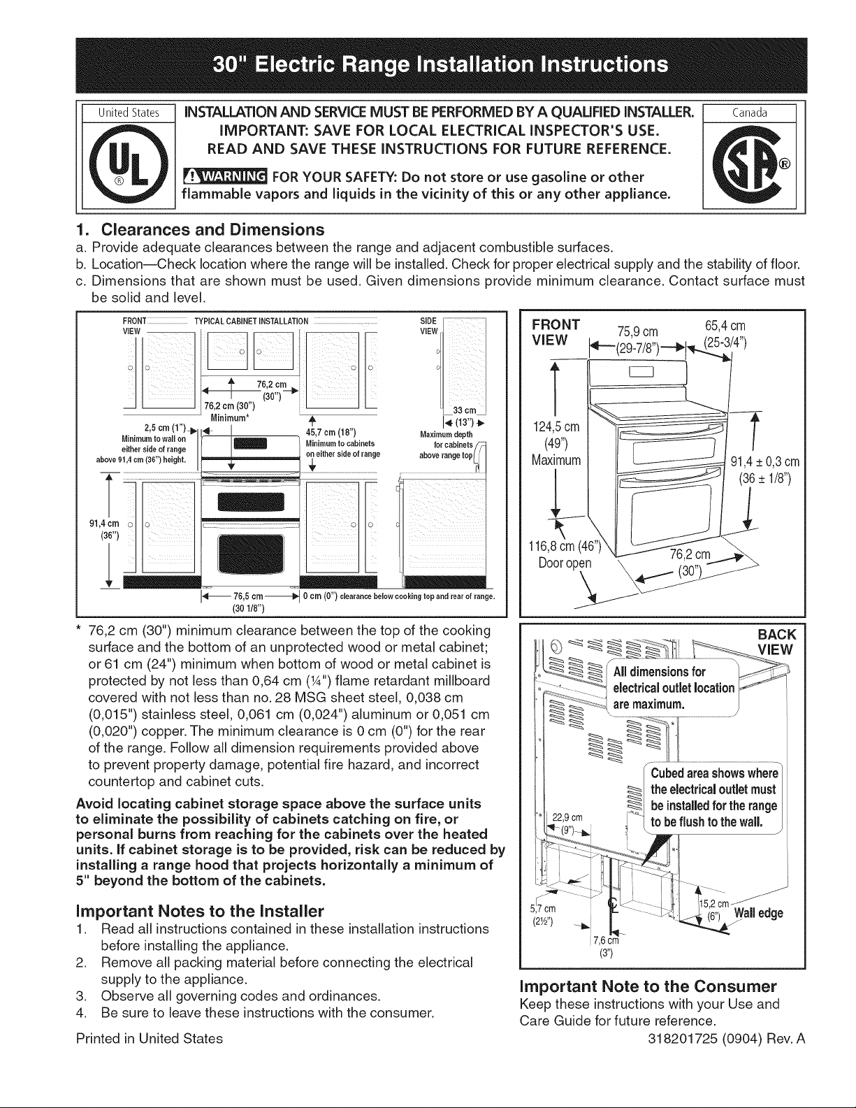
1. Clearances and Dimensions
a. Provide adequate clearances between the range and adjacent combustible surfaces.
b. Location--Check location where the range will be installed. Check for proper electrical supply and the stability of floor.
c. Dimensions that are shown must be used. Given dimensions provide minimum clearance. Contact surface must
be solid and level.
FRONT TYPICAL CABINET iNSTALLATION ................. SIDE
ViEWVIEW
FRONT 75,9cm 65,4crn
VIEW (25-3/4")
1
2,5 crn (1")_ _ I
either side of range
Minimum to wall on _ /
above 91,4 cm (36") height.
91,4cm_ _ --_ .....
76,2 cm (30") minimum clearance between the top of the cooking
surface and the bottom of an unprotected wood or metal cabinet;
or 61 cm (24") minimum when bottom of wood or metal cabinet is
protected by not less than 0,64 cm (W') flame retardant millboard
covered with not less than no. 28 MSG sheet steel, 0,038 cm
(0,015") stainless steel, 0,061 cm (0,024") aluminum or 0,051 cm
(0,020") copper. The minimum clearance is 0 cm (0") for the rear
of the range. Follow all dimension requirements provided above
to prevent property damage, potential fire hazard, and incorrect
countertop and cabinet cuts.
Avoid locating cabinet storage space above the surface units
to eliminate the possibility of cabinets catching on fire, or
personal burns from reaching for the cabinets over the heated
units. If cabinet storage is to be provided, risk can be reduced by
installing a range hood that projects horizontally a minimum of
5" beyond the bottom of the cabinets.
, t (38,,)!/ I
176,20m(30") I I
Minimum* _, _- (13")
75,5 crn
(30 1/8")
45,7 crn(18") Maximumdepth
Minimum to cabinets
...... abevefercab,netS_rangetep_,_,,
O cm (0") clearancebelow cookingtop and rear of range.
Important Notes to the Installer
1. Read all instructions contained in these installation instructions
before installing the appliance.
2. Remove all packing material before connecting the electrical
supply to the appliance.
3. Observe all governing codes and ordinances.
4. Be sure to leave these instructions with the consumer.
Printed in United States
T
124,5crn
(49")
Maximum
116,8 cm (46")
u00ropen \ (30") j/%
76,2cm_-.
_,_'__-:_ _l _ .....
IIdmmens=ons
:L- ........_°'_1electricaloutletlocationY-
_-_ _aremaximum.
........... ............................................
Cubedareashowswhere
theelectricaloutletmust
i 229cm _"_'_ ....
'I-i9 ) i tO De1"lushto thewall..
<- ::::::::-/- i i . .....
( _lb_j 7 6 c_m..
(3')
Important Note to the Consumer
Keep these instructions with your Use and
Care Guide for future reference.
beinstalledforthe range
318201725 (0904) Rev. A
-t
91,4_+0,3crn
(36+ 1/8")
BACK
Page 2
2. Install Anti-Tip Bracket
iMPORTANT SAFETY WARNING
To reduce the risk of tipping of the range, the range
must be secured to the floor by properly installed anti-
tip bracket and screws packed with the range. These
parts are located in a plastic bag in the oven. Failure
to install the anti-tip bracket will allow the range to tip
over if excessive weight is placed on an open door or
if a child climbs upon it. Serious injury may result from
spilled hot liquids or from the range itself. Refer to the
instructions located in the anti-tip bracket package for
proper bracket installation. If the range is moved to
a different location, the anti-tip bracket must also be
moved and installed with the range.
For the bracket installation instructions, refer to
the anti-tip bracket template shipped in the anti=tip
bracket package.
= Serial Plate
Information
The serial plate
is located as
shown below. See
the serial plate
for the following
information:
A. Model, lot and
serial number of
range.
B. Kilowatt
rating (power
requirements).
C. Voltage ratings.
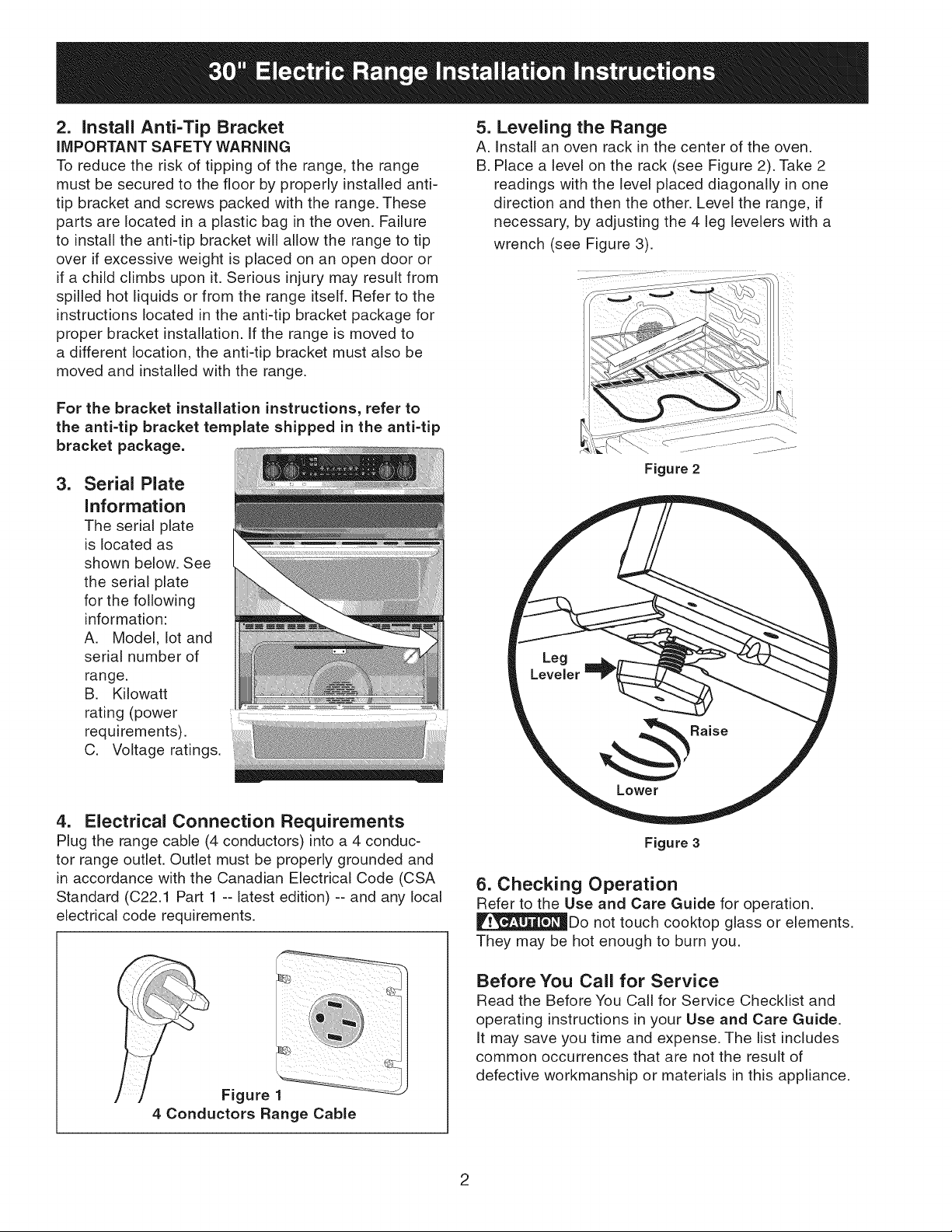
5. Leveling the Range
A. Install an oven rack in the center of the oven.
B. Place a level on the rack (see Figure 2). Take 2
readings with the level placed diagonally in one
direction and then the other. Level the range, if
necessary, by adjusting the 4 leg levelers with a
wrench (see Figure 3).
Figure 2
4. Electrical Connection Requirements
Plug the range cable (4 conductors) into a 4 conduc-
tor range outlet. Outlet must be properly grounded and
in accordance with the Canadian Electrical Code (CSA
Standard (C22.1 Part 1 -- latest edition) -- and any local
electrical code requirements.
Figure 1
4 Conductors Range Cable
Figure 3
6. Checking Operation
Refer to the Use and Care Guide for operation.
_Do not touch cooktop glass or elements.
They may be hot enough to burn you.
Before You Call for Service
Read the Before You Call for Service Checklist and
operating instructions in your Use and Care Guide.
it may save you time and expense. The list includes
common occurrences that are not the result of
defective workmanship or materials in this appliance.
Page 3

Etats-Unis
L'INSTALLATION ET L'ENTRETIEN DOIVENT f=TRE EFFECTUES PAR UN
IN STALLATE UR QUALI FIE.
Canada
IMPORTANT : CONSERVEZ POUR L'INSPECTEUR D'ELECTRICITF: LOCAL.
LISEZ ET CONSERVEZ CES INSTRUCTIONS POUR RI_F#RENCES ULTERIEURES.
POUR VOTRE SECURITE : N'entreposez pas ou n'utilisez pas
d'essence ou d'autres produits inflammables a proximit_ de cet appareil ou de
tout autre appareil _lectrom_nager.
1. Espaces pr_vus et dimensions
a. Laissez suffisamment d'espace entre la cuJsiniere et les surfaces combustibles adjacentes.
b. Endroit - Wrifiez I'endroit ok la cuisiniere sera installee, Assurez-vous qu'il y a une source d'alimentation
electrique adequate et que le plancher est solide.
c. Les dimensions qui sent donn_es doivent _tre respectees, Ces dimensions allouent un minimum de jeu. Les
surfaces en contact doivent _tre solides et de niveau.
VUEDE INSTALLATIONTYPIQUEDELACUISlNII_RE
VUEDEooTE_
VUE DE
FACE
i
i
1
i
2,5cm (1") Minimum* 4_
Distance minimale _ _ 45,7cm(18")
du rnur de chaque c6t_ de _ _ Distance minimale ;_
la cuisini_re au dessus de I'armeire de chaque
91,4 cm (36") de haut. _ c6t_ de la cuisini_re
du cabinet au-desaus
' 33cm
Profondeur maximale
1403")
91,4(:_
ii i
_ 7&5 cm_ 0cm (0") d_gagementen-dessous
(301/8") dela surface de cuisson et _ I'arri_re
Espace minimum de 76,2 cm (30") entre le dessus de la surface de
cuisson et le dessous d'une armoire en bois ou en metal non proteg6e,
ou espace minimum de 61 cm (24") si lefond de I'armoire en bois
ou en metal est proteg6 par un panneau resistant au feu d'au moins
0,64 cm (1/4") recouvert d'une feuille d'acier doux dent I'epaisseur
est au moins de 0,038 cm (0,015") si en acier inoxydable; de 0,061
cm (0,024") si en aluminium ou de 0,051cm (0,020") si en cuivre. Un
espace de 1,3 cm (W') min. pour I'arriere et les c6tes de la cuisiniere
est requis. Respectez routes les dimensions indiquees ci dessus afin
d'eviter des dommages & la propriete, de creer un danger potentiel
d'incendie et de fake des decoupages incorrects du comptoir et de
I'armoire.
I_vitez d'ajouter des espaces de rangement au-dessus de I'appareil
pour _liminer tout risque de br_3Jures ou de feu en vous penchant
au-dessus de surfaces chaudes pour prendre des objets. Si des
espaces de rangement doivent 6tre ajout_s, les risques peuvent
6tre r6duits en installant une hotte qui exc_de le devant de I'armoire
d'au moins 12,7 cm (5").
Notes importantes a I'installateur
1. LJretoutes les instructions contenues dans ce feuJllet avant de
preceder & I'installation de I'appareil.
2. Enlever tout le materiel d'emballage avant de brancher I'appareJl.
3. Observer tousles codes et reglements,
4. Laisser ces instructions au consommateur.
Imprime aux Etats-Unis
_,) _ _ _ _ __z_% t,li _-_ ARRIERE
VUE
uteslesd_men
, : i- --'_1I°calisati°n dela prisede r
__ _Les cubes representent "_
_ I'emplacement oa la
prise de courant dolt
_tre install_e pour que
_'appareil soit le plus
; 229cm nr"*- "" m" r
Jl-- i i
7cm i _ -_ :11:11:::1::;.<i _5;2cm Borddu
7,6cm
(3")
Note importante au proprietaire
Conserver ces instructions ainsi que le manuel
d'utilJsation de I'appareJl pour reference future.
318201725 (0904) Rev. A
Page 4

2. Installation du support anti-bascule
AVERTISSEMENT DE sf==cURITE iMPORTANT
Pour reduire le risque de basculement de la cuisiniere,
protegez-la en installant le support anti-bascule fourni
avec la cuisiniere. II est situe dans un sac de plastique
dans le four. Si vous n'installez pas ce support, la
cuisiniere risque de basculer si un poids excessif est
place sur la porte ouverte ou si un enfant y grimpe.
Les renversements de liquides chauds ou la cuisiniere
peuvent provoquer de serieuses blessures. Suivez
les instructions situees dans I'enveloppe client pour
installer adequatement le support anti-bascule. Si vous
deplacez la cuisiniere pour I'installer _.un autre endroit,
vous devez _galement deplacer le support pour le
reinstaller avec la cuisiniere.
5. Mise _ niveau de la cuisinibre
A. Installez une grille au centre du four.
B. Deposez un niveau _.bulle sur la grille (Figure 2).
Prenez 2 lectures en plagant le niveau en diagonale
dans une direction, puis dans I'autre direction. Si
necessaire, ajustez les 4 vis de nivellement & I'aide
d'une cle pour niveler I'appareil (Figure 3).
R_f_rez-vous au gabarit d'installation du support
anti=bascule situ_ darts I'enveloppe client pour
connaffre les _tapes d'installation du support anti-
bascule.
3. Information
concemant la
plaque de s6rie
La plaque de serie
est situee tel que
montr_ plus bas. Les
informations suivantes
s'y trouvent:
A. Les num_ros de
modele, de lot et de
serie de I"appareil.
B. Le regime nominal
en kilowatts (requis
electrique).
C. La tension nominale.
4. Branchement
Branchez le c&ble d'alimentation de la cuisiniere (4
conducteurs) & une prise murale munie de 4 conduc-
teurs. La prise murale dolt _tre correctement raise & la
terre et conforme au code electrique canadien (la norme
de I'ACNOR C22.1 parfie 1 - derniere edition) et autres
codes Iocaux.
Figure 2
Patte de
nivellement ""
_._
Monter
Baisser
Figure 3
6. V6rification du Fonctionnement
R_ferez-vous au Manuel d'utilisation et d'entretien
fourni avec la cuisiniere pour les directives de
fonctionnement d'entretien et de nettoyage.
Ne touchez pas aux elements. IIs
peuvent _tre assez chauds pour causer des br01ures.
Avant d'appeler le service d'entretien
Revisez la liste des v_rifications preventives et
les instructions d'operation dans votre Manuel
d'utilisation et d'entretien. Vous sauverez
probablement du temps et de I'argent. La liste contient
les evenements ordinaires qui ne resultent pas de
defectuosites dans le materiel ou la fabrication de cet
appareil.
Figure 1
Cfible de la cuisinibre fi 4 Conducteurs
 Loading...