

Page 1

TABLE OF CONTENTS
Important Safety Instructions ........................... 2-3 Accessories ...................................................... 19
Installatton Requirements .............................. 4-10 Notes ............................................................. 20
Installabon Instructions ................................ 11-16 Fran_als .......................................................... 21
Reversmg Door ............................................ 17-18 Espa_ol ........................................................... 41
oo
3>
oo
Page 2
For your safety the information in this manual must be followed to minimize the risk of fire or explosion or to prevent
property damage, personal injury or loss of life. Do not store or usegasoline or other flammable vapors and liquids in
....the vidnity °f th!s °! any °ther app!!ance:......................................................................................................................................................................................................................................................................................................................
AWARNING - RISK OF FIRE
Read all of the following instructions before installing and using this appliance:
* Destroy the carton and plastic bags after the dryer is unpacked. Children might use them for play. Cartons covered
with rugs, bedspreads, or plastic sheets can become airtight chambers causing suffocation. Place all materials in a
garbage container or make materials inaccessible to children.
* Clothes dryer installation and service must be performed by a qualified installer, service agency or the gas supplier.
* Install the clothes dryer according to the manufacturer's instructions and local codes.
* The electrical service to the dryer must conform with local codes and ordinances and the latest edition of the
National Electrical Code, ANS[/NFPA 70, or in Canada, the Canadian electrical code C22.I part 1.
* The gas service to the dryer must conform with local codes and ordinances and the latest edition of the National
Fuel Gas Code ANSI Z223.1, or in Canada, CAN/ACG BI49.1-2000. An individual manual shut-off valve must be
installed within 6 ft (i.83 m) of the dryer in accordance with the National Fuel Gas Code, ANSI Z223.1/NFPA 54.
* The dryer is designed under ANSI Z 21.5.1 or ANS[/UL 2158 - CAN/CSA C22.2 No. i12 (latest editions) for HONE
USE only. This dryer is not recommended for commercial applications such as restaurants, beauty salons, etc.
* Do not install a clothes dryer with flexible plastic or flexible foil venting material. Flexible venting materials are
known to collapse, be easily crushed and trap lint. These conditions will obstruct clothes dryer airflow and increase
the risk of fire.
* The instructions in this manual and all other literature included with this dryer are not meant to cover every
possible condition and situation that may occur. Good safe practice and caution NUST be applied when installing,
operating and maintaining any appliance.
WHAT TO DO IF YOU SMELL GAS:
* Do not try to light any appliance.
* Do not touch any electrical switch; do not use any
phone in your building.
* Clear the room, building or area of all occupants.
* Immediately call your gas supplier from a neighbor's
phone. Follow the gas supplier's instructions.
* If you cannot reach your gas supplier, call the fire
department.
personmoveor !!It theapp!iance: ..................
Save these instructions
for future reference.
Tools and materials needed for installation:
Pre-Installation Requirements
* Adjustable pliers * Carpenter's level
* Phillips, straight, & square bit * External vent hood
screwdrivers * 4-inch (!02 mm), rigid metal or
* Adjustable wrench semi-rigid metal exhaust duct work
* Pipewrench for gas supply (gas * 3-wire or 4-wire 240 volt cord kit
dryer) (electric dryer)
* @-resistant thread tape (for natural * 4 in. (!02 mm) clamp
gas or LP supply, gas dryer)
* Gas line shutoff valve (gas dryer)
* _/2NPTunion flare adapters (x2)
and flexible gas supply line (gas
dryer)
Netal foil tape (not duct tape)
Page 3
Pleasereadallinstructionsbeforeusingthisdryer.
Exhaust Venting
Free-flowing, clear of lint buildup
4 inch (102 mm) rigid or semi-rigid ducting of
Recognize safety syrnboisr words
and labels
Safety items throughout this manual are labeled with
a WARNING or CAUTION based on the risk type as
described below:
Definitions
This is the safety alert symbol. It is used to alert
you to potential personal injury hazards. Obey all safety
messages that follow this symbol to avoid possible injury
or death.
DANGER indicates an imminently hazardous situation
which if not avoided will result in death or serious
injury, 240v Electric Supply (Electric Dryer)
CAUTION indicates a potentially hazardous situation E3 Test hinge and latch for function
which, if not avoided, may result in minor or moderate
injury. Electrical Power
IMPORTANT indicates installation, operation or
maintenance information which is important but not
hazard-related.
minimal length and turns
E_ NO foil or plastic venting material
E_ Approved vent hood exhausted to outdoors
Leveling
E_ Dryer is level, side-to-side and front-to-back
E3 Cabinet is setting solid on all corners
GasSupplyCGasDryer:
E_ Manual shutoff valve present in supply
E_ AIt connections sealed with approved sealer and
wrench tight
E_ Conversion kit for LPsystem
E_ Gas supply turned on
E3 No leaks present at all connections -
check with soapy water, NEVERcheck with flame
E3 Approved NEMA 10-30R or 14-30R service cord
with all screws tight on terminal block
E3 Approved strain relief installed
E3 Terminal access cover installed before initial
operation
Door Reversal
E3 Follow detailed instructions in this guide
E3 House power turned on
E3 Dryer plugged in
Final Checks
Installation Instructions and Use and Care
Guide read thoroughly
Door latches and drum tumbles when cycle
starts
Registration card sent in
Page 4
Becauseofpotentiallyinconsistentvoltagecapabilities,theuseofthisdryerwithpowercreatedbygaspowered
generators,solarpoweredgenerators,windpoweredgeneratorsoranyothergeneratorotherthanthelocalutility
companyisnotrecommended,
Electrical requirements for electric dryer
CIRCUIT - Individual 30 amp. branch circuit fused with 30 amp. time delay fuses or circuit breakers. Use separately
fused circuits for washer and dryer. DO NOToperate a washer and a dryer on the same circuit.
POWER SUPPLY- 3-wire or 4-wire, 240 volt, single phase, 60 Hz, Alternating Current.
through the neutral.
OUTLET RECEPTACLE- NEMA 10-3ORor NEMA 14-30R rece )tacie to be located so the power supply cord is accessible
when the dryer is in the installed position.
GROUNDING CONNECTION - See "Grounding requirements" in Electrical Installation section.
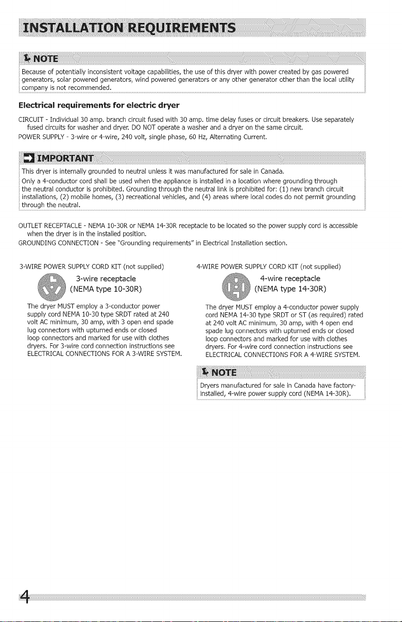
3-WIRE POWERSUPPLYCORD KIT (not supplied)
3-wire receptacle
(NEMA type 10-30R)
The dryer MUSTemploy a 3-conductor power
supply cord NEMA 10-30 type SRDTrated at 240
volt AC minimum, 30 amp, with 3 open end spade
lug connectors with upturned ends or closed
loop connectors and marked for use with clothes
dryers. For 3-wire cord connection instructions see
ELECTRICALCONNECTIONS FOR A 3-WIRE SYSTEM.
4-WIRE POWER SUPPLYCORD KIT (not supplied)
4-wire receptacle
(NEMA type 14-30R)
The dryer MUST employ a 4-conductor power supply
cord NEMA 14-30 type SRDTor ST (as required) rated
at 240 volt AC minimum, 30 amp, with 4 open end
spade lug connectors with upturned ends or closed
loop connectors and marked for use with clothes
dryers. For 4-wire cord connection instructions see
ELECTRICALCONNECTIONS FORA 4-WIRE SYSTEM.
Page 5
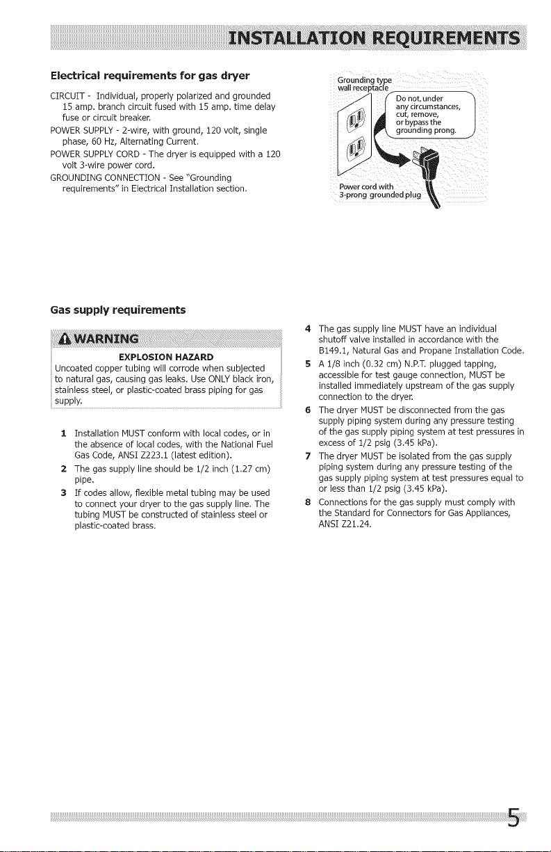
Electrical requirements for gas dryer
CIRCUIT - Individual, properly polarized and grounded
15 amp. branch circuit fused with 15 amp. time delay
fuse or circuit breaker.
POWER SUPPLY- 2-wire, with ground, !20 volt, single
phase, 60 Hz, Alternating Current.
POWER SUPPLYCORD- The dryer is equipped with a 120
volt 3-wire power cord.
GROUNDING CONNECTION - See "Grounding
requirements" in Electrical Installation section.
Gas supply requirements
; EXPLOSION HAZARD
Uncoated copper tubing will corrode when subjected
to natural gas, causing gas leaks. Use ONLYblack iron,
stainless steel, or plastic-coated brass piping for gas
supply.
1 Installation MUST conform with local codes, or in
the absence of local codes, with the National Fuel
Gas Code, ANSI Z223.I (latest edition).
2 The gas supply line should be 1/2 inch (1.27 cm)
pipe.
3 If codes allow, flexible metal tubing may be used
to connect your dryer to the gas supply line. The
tubing MUST be constructed of stainless steel or
plastic-coated brass.
Groundingtype
wal receptacle
/ _.\ I |anycircurnstances
_- Do not,under -"
\ I_ grounding prong.
h
B-pronggroundedpl
4. The gas supply line MUST have an individual
shutoff valve installed in accordance with the
B!49.!, Natural Gas and Propane Installation Code.
5 A !/8 inch (0.32 cm) N.P.T.plugged tapping,
accessible for test gauge connection, MUST be
installed immediately upstream of the gas supply
connection to the dryer.
6 The dryer MUSTbe disconnected from the gas
supply piping system during any pressure testing
of the gas supply piping system at test pressures in
excess of !/2 psig (3.45 kPa).
7 The dryer MUSTbe isolated from the gas supply
piping system during any pressure testing of the
gas supply piping system at test pressures equal to
or tessthan Z/2 psig (3.45 kPa).
8 Connections for the gas supply must comply with
the Standard for Connectors for Gas Appliances,
ANSI Z21.24.
Page 6
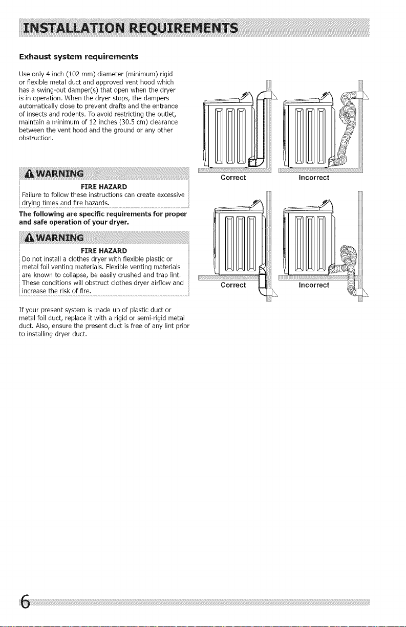
Exhaust system requirements
Use only 4 inch (i02 mm) diameter (minimum) rigid
or flexible metal duct and approved vent hood which
has a swing-out damper(s) that open when the dryer
is in operation. When the dryer stops, the dampers
automatically close to prevent drafts and the entrance
of insects and rodents. To avoid restricting the outlet,
maintain a minimum of !2 inches (30.5 cm) clearance
between the vent hood and the ground or any other
obstruction.
Failure to follow these instructions can create excessive
FIRE HAZARD
drying times and fire hazards.
The following are specific requirements for proper
and safe operation of your dryer,
li;;:_:_;:;_!! :_iiiii; ;_i¸__;i;_¸i¸!_;;_i_ii ;_11 iiii
Correct
Do not install a clothes dryer with flexible plastic or
FIRE HAZARD
metal foil venting materials. Flexible venting materials
are known to collapse, be easily crushed and trap tint.
These conditions witt obstruct clothes dryer airflow and
increase the risk of fire.
If your present system is made up of plastic duct or
metal foil duct, replace it with a rigid or semi-rigid metal
duct. Also, ensure the present duct is free of any lint prior
to installing dryer duct.
[_; ¸i¸i¸i¸i¸i¸i¸i¸i¸i¸i¸i¸i¸i¸i¸i¸i
L
Incorrect
Page 7
Exhaust system requirements, continued
FIRE HAZARD FIRE HAZARD
A clothes dryer must be exhausted outdoors• Do not Exceeding the length of duct pipe or number of elbows
exhaust dryer into a chimney, a wall, a ceiling, an attic, allowed in the "MAXIMUM LENGTH" charts can cause
a crawl space or any concealed space of a building• A an accumulation of lint in the exhaust system• Plugging
clothes dryer produces combustible lint. If the dryer is
not exhausted outdoors, some fine lint will be expelled
into the laundry area• An accumulation of tint in any
area of the home can create a health and fire hazard.
The dryer must be connected to an exhaust outdoors.
Regularly inspect the outdoor exhaust opening and
remove any accumulation of lint around the outdoor
exhaust opening and in the surrounding area.
FIRE HAZARD
Do not allow combustible materials (for example:
clothing, draperies/curtains, paper) to come in
contact with exhaust system. The dryer MUST NOT
be exhausted into a chimney, a wall, a ceiling,
or any concealed space of a building which can
accumulate lint, resulting in a fire hazard.
Do not screen the exhaust ends of the vent system,
or use any screws, rivets or other fasteners that
extend into the duct to assemble the exhaust
system. Lint can become caught in the screen, on
the screws or rivets, clogging the duct work and material.
creating a fire hazard as welt as increasing drying
..... * If nsta ngsem-rgdventng do not exceed8ft
t mes Use an approved vent hood to term nate the "2 4 m" duct len th
• _. ) g •
duct outdoors, and seal all ]omts wtth metal fotl duct .....
tape, All male duct pipe fittings MUST be instalied
downstream with the flow of air.
the system could create a fire hazard, as welt as
increase drying times.
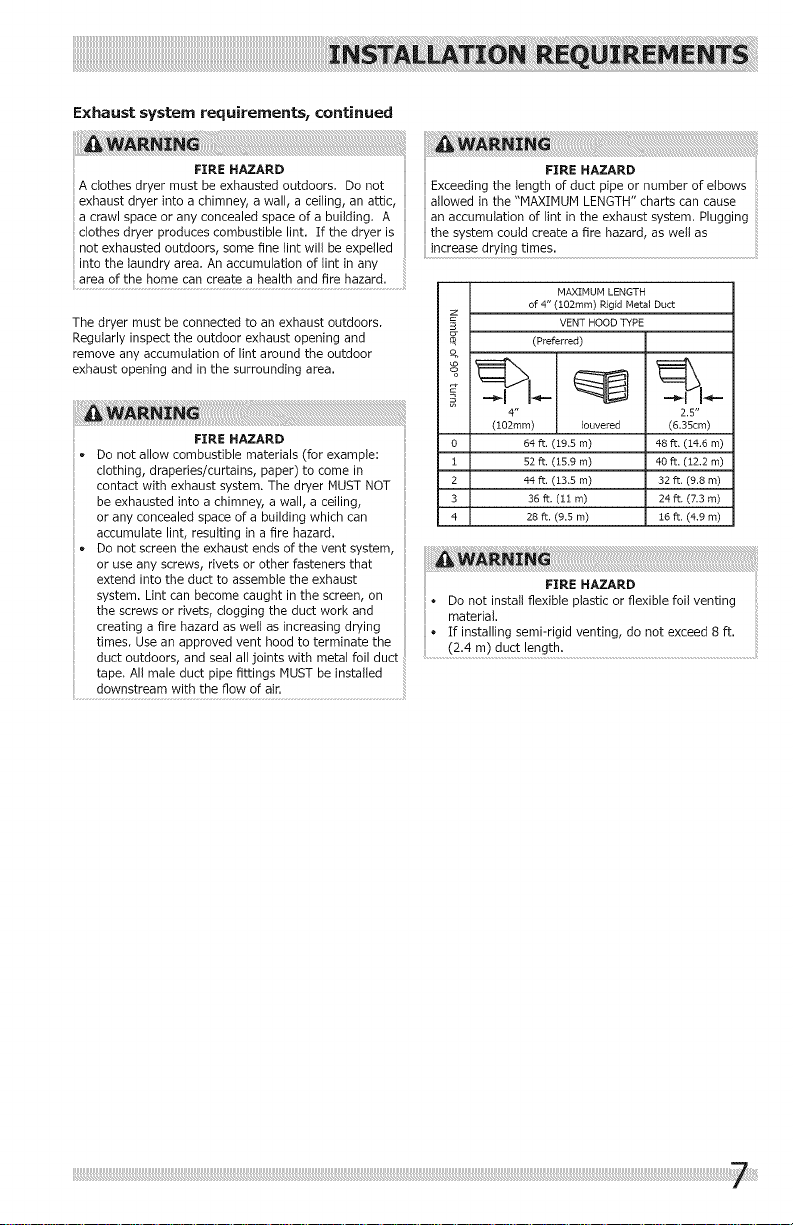
MAXIMUM LENGTH
of 4" (102mm) Rigid Metal Duct
9 VENT HOOD TYPE
0 64 ft. (19.5 m) 48 ft. (14.6 m)
1 52 ft. (15,9 m) 40 ft, (12.2 m)
2 44 ft. (13,5 m) 32 ft, (9.8 m)
3 36 ft. (11 m) 24 ft. (7.3 m)
4 28 ft. (9,5 m) 16 ft, (4.9 m)
(Preferred)
4" 2.5"
(102ram) Iouvered (6.35cm)
o Do not install flexible plastic or flexible foil venting
Page 8
Exhaust system requirements, continued
Install male fittings in correct direction:
CORRECT INCORRECT
In installations where the exhaust system is not described
in the charts, the following method must be used to
determine if the exhaust system is acceptable:
:1. Connect an inclined or digital manometer between
the dryer and the point the exhaust connects to the
dryer.
2 Set the dryer timer and temperature to Air Dry and
start the dryer.
3 Read the measurement on the manometer.
4 The system back pressure MUST NOT be higher
than 0.75 inches of water column. If the
system back pressure is tess than 0.75 inches of
water column, the system is acceptable. If the
manometer reading is higher than 0.75 inches of
water column, the system is too restrictive and the
installation is unacceptable.
Although vertical orientation of the exhaust system is
acceptable, certain extenuating circumstances could
affect the performance of the dryer:
• Only rigid metal duct work should be used.
• Venting vertically through a roof may expose the
exhaust system to down drafts causing an increase
in vent restriction.
• Running the exhaust system through an
uninsulated area may cause condensation and
faster accumulation of lint.
• Compression or crimping of the exhaust system will
cause an increase in vent restriction.
• The exhaust system should be inspected and
cleaned a minimum of every 18 months with
normal usage. The more the dryer is used, the
more often you should check the exhaust system
and vent hood for proper operation.
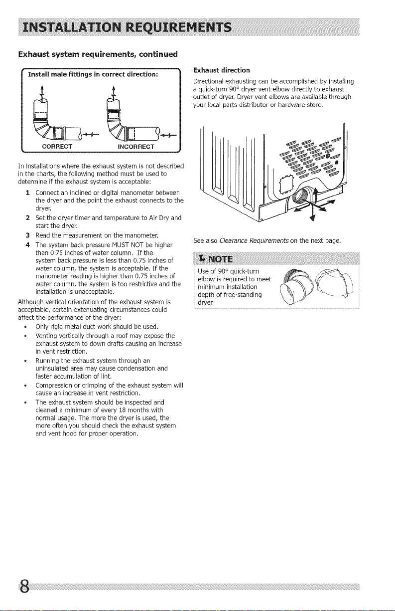
Exhaust direction
Directional exhausting can be accomplished by installing
a quick-turn 90 ° dryer vent elbow directly to exhaust
outlet of dryer. Dryer vent elbows are available through
your local parts distributor or hardware store.
See also Clearance Requirements on the next page.
Use of 90 ° quick-turn
elbow is required to meet
minimum installation
depth of free-standing
dryer.
Page 9
Manufactured or mobile home installation
1 Installation MUST conform to current Manufactured
Home Construction & Safety Standard, Title 24
CFR, Part 32-80 (formerly the Federal Standard
for Mobile Home Construction and Safety, Title 24,
HUD Part 280) or Standard CAN/CSAZ240 MH.
2 Dryer MUST be exhausted outside (outdoors, not
beneath the mobile home) using metal ducting
that wilt not support combustion. Metal ducting
must be 4 inches (i0.i6 cm) in diameter with no
obstructions. Rigid metal duct is preferred.
3 If dryer is exhausted through the floor and area
beneath the mobile home is enclosed, the exhaust
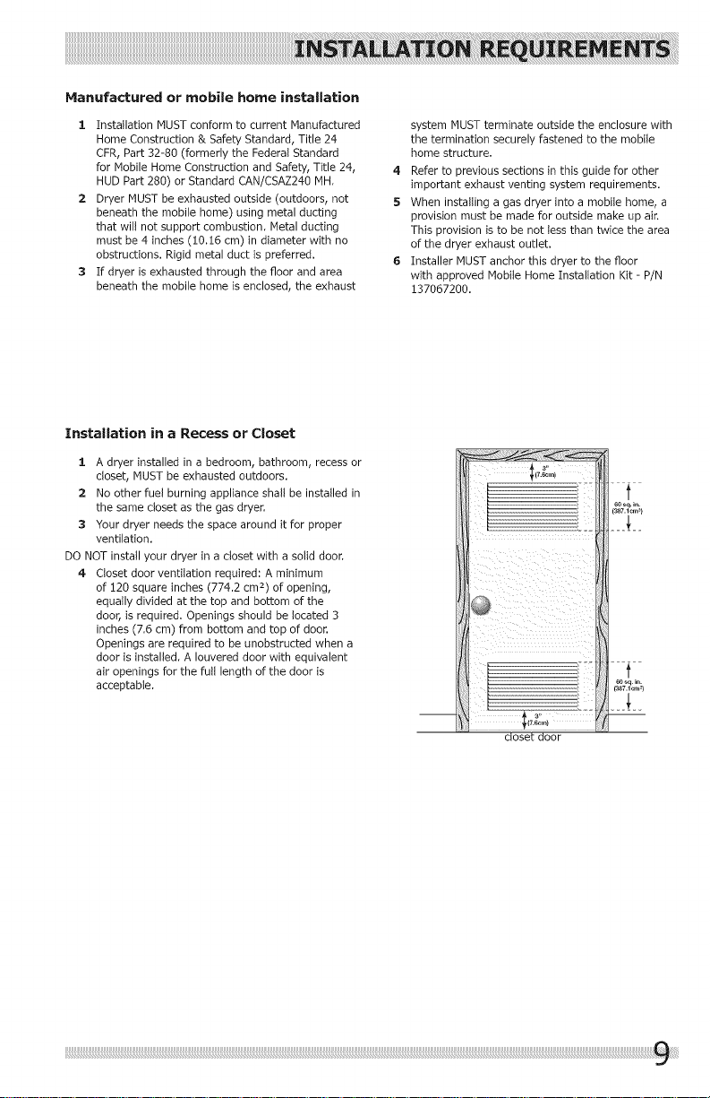
Installation in a Recess or Closet
1 A dryer installed in a bedroom, bathroom, recess or
closet, MUST be exhausted outdoors.
2 No other fuel burning appliance shall be installed in
the same closet as the gas dryer.
3 Your dryer needs the space around it for proper
ventilation.
DO NOT install your dryer in a closet with a solid door.
4 Closet door ventilation required: A minimum
of !20 square inches (774.2 cm 2) of opening,
equally divided at the top and bottom of the
door, is required. Openings should be located 3
inches (7.6 cm) from bottom and top of door.
Openings are required to be unobstructed when a
door is installed. A Iouvered door with equivalent
air openings for the full length of the door is
acceptable,
system MUST terminate outside the enclosure with
the termination securely fastened to the mobile
home structure.
4 Refer to previous sections in this guide for other
important exhaust venting system requirements.
5 When installing a gas dryer into a mobile home, a
provision must be made for outside make up air.
This provision is to be not less than twice the area
of the dryer exhaust outlet.
6 Installer MUST anchor this dryer to the floor
with approved Mobile Home Installation Kit - P/N
137087200.
closet door
Page 10
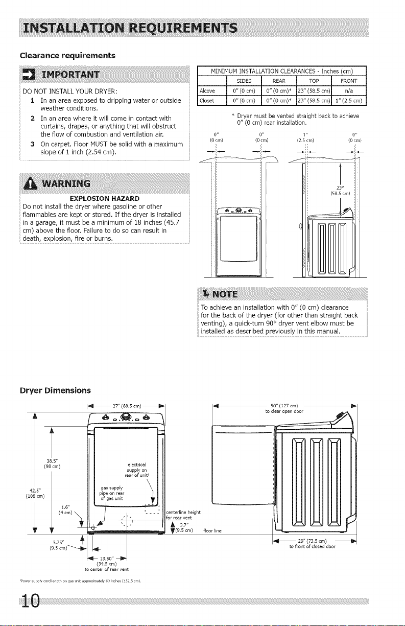
Clearance requirements
INSTALLYOUR DRYER:
I In an areaexposedtodrippingwateroroutside
weatherconditions.
2 In an areawhere itwillcome incontactwith
curtains,drapes,or anythingthatwillobstruct
theflowofcombustionand ventilationair.
3 On carpet.FloorMUST be solidwitha maximum
slope of i inch (2.54 cm).
MINIMUM INSTALLATION CLEARANCES - Inches (cm)
SIDES REAR TOP FRONT
Alcove 0" (0 cm) 0" (O cm)* 23" (58.5 cm) n/a
Closet 0"(0 crn) 0" (0 cm) _ 23" (58.5 crn) 1" (2.5 crn)
* Dryer must be vented straight back to achieve
0" (0 cm) rear installation.
(oO#i_) o"
(0cm)
1" "
(2.5 cm) (00cm)
_ii_ -iL
Do not install the dryer where gasoline or other
EXPLOSION HAZARD
flammables are kept or stored. If the dryer is installed
in a garage, it must be a minimum of !8 inches (45.7
cm) above the floor. Failure to do so can result in
death, explosion, fire or burns.
Dryer Dimensions
I_ 27' (68,5 cm)
42,5"
(108 cm)
38,5"
(98 cm)
electrical
supply on
rear of unitI
pipe on rear
gas supply _
of gas unit
:enterline height
3.7"
(9,5 cm) floorline
To achieve an installation with 0" (0 cm) clearance
for the back of the dryer (for other than straight back
venting), a quick-turn 90 ° dryer vent elbow must be
installed as described previously in this manual,
S0" (127cm) _lJ
to
I_ 29" (73,5 cm)
to front of dosed door
(34,5 cm)
to center of rear vent
iPowe, sul)ply cmd length on gas unit ap]3mxima_ely 6O in( he£ (1525 cm)
i!!i!i!l!_!0 ill
Page 11
Electrical installation
The following are specific requirements for proper and
safe electrical installation of your dryer. Failure to follow
these instructions can create electrical shock and/or a
fire hazard.
ELECTRICAL SHOCK HAZARD
This appliance MUST be properly grounded.
Electrical shock can result if the dryer is not properly
grounded. Follow the instructions in this manual for
o
proper grounding.
extension cords are not designed to withstand the
amounts of electrical current this dryer utilizes
and can melt, creating electrical shock and/
or fire hazard. Locate the dryer within reach of
the receptacle for the length power cord to be
• Do not use an extension cord with this dryer. Some
purchased, allowing some slack in the cord. Refer to
the pre-installation requirements in this manual for
the proper power cord to be purchased power supply.
• A U.L.-approved strain relief must be installed onto
Grounding requirements - Electric dryer (USA)
conductor can result in a risk of electrical shock. Check
with a licensed electrician if you are in doubt as to
whether the appliance is properly grounded.
For a grounded, cord-connected dryer:
1 The dryer MUST be grounded. In the event of a
malfunction or breakdown, grounding will reduce
the risk of electrical shock by a path of least
resistance for electrical current.
2 After you purchase and install a 3 wire or 4 wire
power supply cord having an equipment-grounding
conductor and a grounding plug that matches you
3 DO NOT modify the plug you've installed on this
For a permanently connected dryer:
1 The dryer MUST be connected to a grounded
ELECTRICAL SHOCK HAZARD
power cord. If the strain relief is not attached, the
cord can be pulled out of the dryer and can be cut
by any movement of the cord, resulting in electrical
shock.
Do not use an aluminum wired receptacle with a
copper wired power cord and plug (or vice versa).
A chemical reaction occurs between copper and
aluminum and can cause electrical shorts. The
proper wiring and receptacle is a copper wired
power cord with a copper wired receptacle.
wiring system, the plug MUSTbe plugged into
an appropriate, copper wired receptacle that is
properly installed and grounded in accordance with
all local codes and ordinances. If in doubt, call a
licensed electrician.
appliance. If it will not fit the outlet, have a proper
outlet installed by a qualified electrician.
metal, permanent wiring system; or an equipment
grounding conductor must be run with the circuit
conductors and connected to the equipment-
grounding terminal or lead on the appliance.
Page 12
Grounding requirements - Electric dryer (Canada)
2 Since your dryer is equipped with a power supply
Improper connection of the equipment grounding
conductor can result in a risk of electrical shock. Check
with a licensed electrician if you are in doubt as to
whether the appliance is properly grounded.
For a grounded, cord-connected dryer:
ELECTRICAL SHOCK HAZARD
cord having an equipment-grounding conductor and
a grounding plug, the plug must be plugged into
an appropriate outlet that is properly installed and
grounded in accordance with all local codes and
ordinances. If in doubt, call a licensed electrician.
3 DO NOT modify the plug provided with this
appliance. If it will not fit the outlet, have a proper
outlet installed by a qualified electrician.
1 The dryer MUST be grounded. In the event of a
malfunction or breakdown, grounding will reduce the
risk of electrical shock by a path of least resistance
for electrical current.
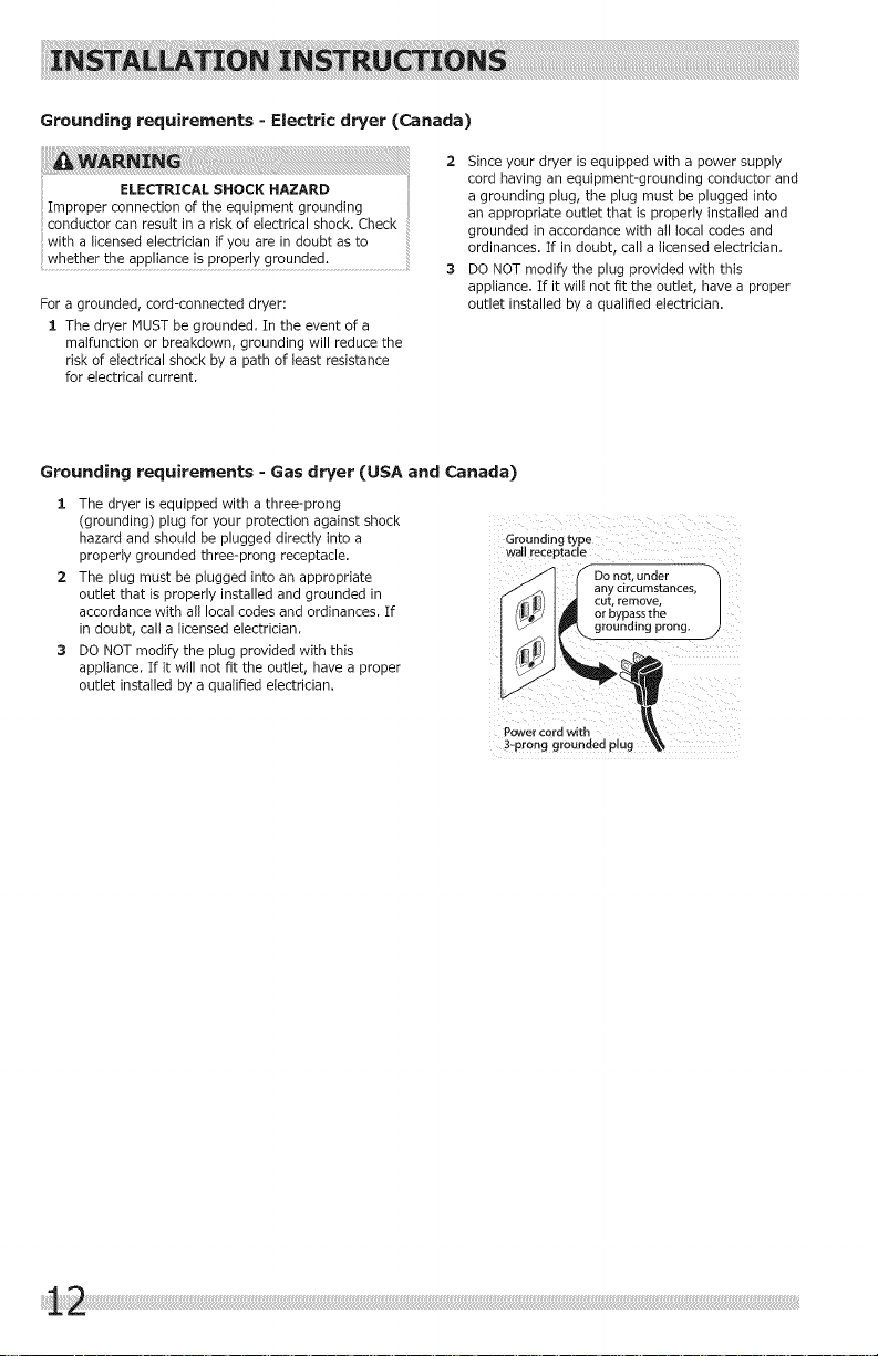
Grounding requirements = Gas dryer (USA and Canada)
1 The dryer is equipped with a three-prong
(grounding) plug for your protection against shock
hazard and should be plugged directly into a
properly grounded three-prong receptacle.
2 The plug must be plugged into an appropriate
outlet that is properly installed and grounded in
accordance with all local codes and ordinances. If
in doubt, call a licensed electrician.
3 DO NOT modify the plug provided with this
appliance. If it will not fit the outlet, have a proper
outlet installed by a qualified electrician.
Grounding type
wail receptacle
Pc_er cord with
3-prong grounded plug
f Do not. under
any circumstances
or bypass the
__ grounding prong.
Page 13
iiiiiiiiiiiiiiiiiiiiiiiiiiiiiiiiiiiiiiiiiiiiiiiiiiiiiiiiiiiiiiiiiiiiiiiiiiiiiiiiiiiiiiiiiiiiiiiiiiiiiiiiiiiiiiiiiiiiiiiiiiiiiiiiiiiiiiiiiiiiiiiiiiiiiiiiiiiiiiiiiiiiiiiiiiiiiiiiiiiiiiiiiiiiiiiiiiiiiiiiiiiiiiiiiiiiiiiiiiiiiiiiiiiiiiiiiiiiiiiiiiiiiiiiiiiiiiiiiiiiiiiiiiiiiiiiiiiiiiiiiiiiiiiiiiiiiiiiiiiiiiiiiiiiiiiiiiiiiiiiiiiiiiiiiiiiiiiiiiiiiiiiiiiiiiiiiiiii_i_i_i_i!!!_i_iiii_!i! _ii _i!_i!i_!i!_iii_i_ii_i_illi_i_ii!i_ii_i_iii!_ii
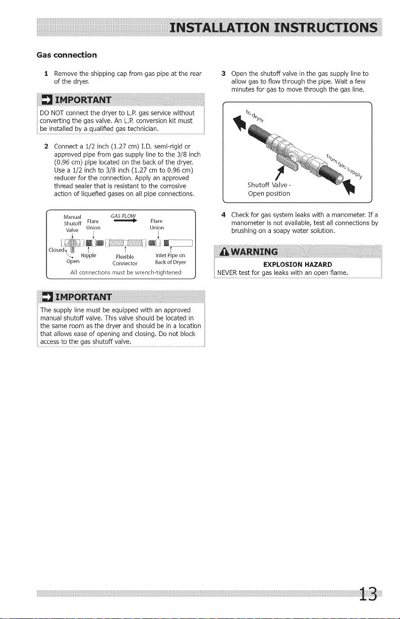
Gas connection
:1. Remove the shipping cap from gas pipe at the rear
of the dryer.
DO NOT connect the dryer to L.P,gas service without
converting the gas valve. An L.P.conversion kit must
be installed by a qualified gas technician.
Connect a 1/2 inch (1.27 cm) I.D. semi-rigid or
approved pipe from gas supply line to the 3/8 inch
(0.96 cm) pipe located on the back of the dryer.
Use a 1/2 inch to 3/8 inch (1.27 cm to 0.96 cm)
reducer for the connection. Apply an approved
thread sealer that is resistant to the corrosive
action of liquefied gases on all pipe connections.
Manua GAS FLOW
Shutoff Flare _ Flare |
Valve Union Union |
,o_/:_ed71_Fi_'_i l_'_:::l_:_\_/_'i I I
: ,_tl t ' t t [
\. Nipple Flexible Inlet Pipe on |
Open Connector Back of Dryer |
All connections mustbe wrench-tightened J
The supply line must be equipped with an approved
manual shutoff valve. This valve should be located in
the same room as the dryer and should be in a location
that allows ease of opening and closing. Do not block
access to the gas shutoff valve.
3 Open the shutoff valve in the gas supply line to
allow gasto flow through the pipe. Wait a few
minutes for gas to move through the gas line.
Open position
4 Check for gas system leaks with a manometer. If a
manometer is not available, test all connections by
l
brushing on a soapy water solution,
Page 14
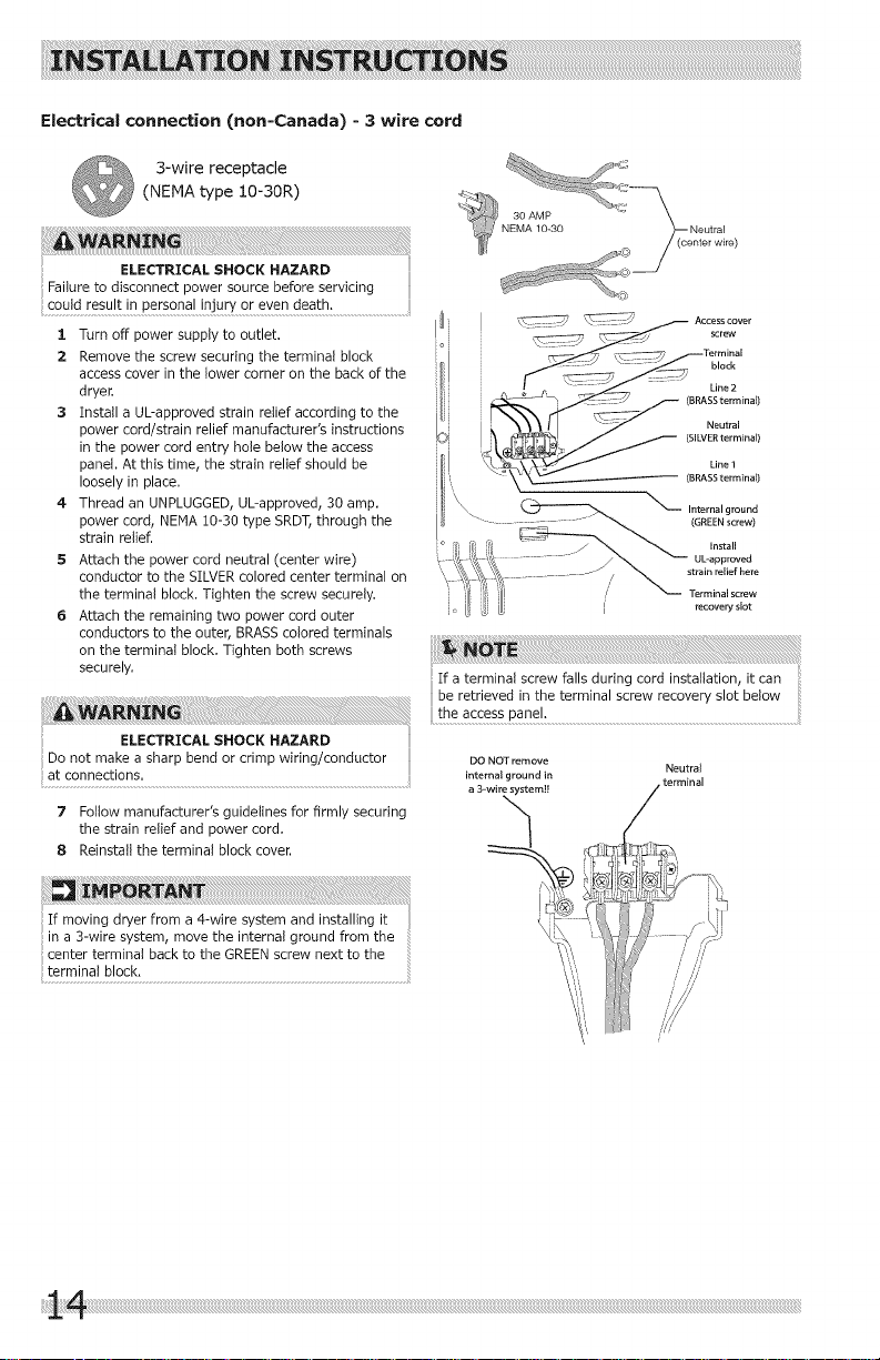
Electrical connection (non=Canada) - 3 wire cord
3-wire receptacle
(NEMA type 10-30R)
Failure to disconnect power source before servicing
ELECTR:CALS.OCK.AzARD
could result in personal injury or even death.
:1. Turn off power supply to outlet.
2 Remove the screw securing the terminal block
access cover in the lower corner on the back of the
dryer.
3 Install a UL-approved strain relief according to the
power cord/strain relief manufacturer's instructions
in the power cord entry hole below the access
panel. At this time, the strain relief should be
loosely in place.
4 Thread an UNPLUGGED,UL-approved, 30 amp.
power cord, NEHA 10-30 type SRDT,through the
strain relief.
5 Attach the power cord neutral (center wire)
conductor to the SILVERcolored center terminal on
the terminal block, Tighten the screw securely.
6 Attach the remaining two power cord outer
conductors to the outer, BRASS colored terminals
on the terminal block, Tighten both screws
securely,
Do not make a sharp bend or crimp wiring/conductor
at connections.
7 Follow manufacturer's guidelines for firmly securing
the strain relief and power cord.
8 Reinstall the terminal block cover.
(SILVER terminal)
Line 1
(BRASS terminal)
_ Internal ground
(GREEN screw)
recoveryslot
If a terminal screw falls during cord installation, it can
DO NOT remove
internal ground in terminal
a 3-wire system]!
Neutral
:If moving dryer from a 4-wire system and installing it
in a 3-wire system, move the internal ground from the
center terminal back to the GREENscrew next to the
terminal block.
Page 15
iiiiiiiiiiiiiiiiiiiiiiiiiiiiiiiiiiiiiiiiiiiiiiiiiiiiiiiiiiiiiiiiiiiiiiiiiiiiiiiiiiiiiiiiiiiiiiiiiiiiiiiiiiiiiiiiiiiiiiiiiiiiiiiiiiiiiiiiiiiiiiiiiiiiiiiiiiiiiiiiiiiiiiiiiiiiiiiiiiiiiiiiiiiiiiiiiiiiiiiiiiiiiiiiiiiiiiiiiiiiiiiiiiiiiiiiiiiiiiiiiiiiiiiiiiiiiiiiiiiiiiiiiiiiiiiiiiiiiiiiiiiiiiiiiiiiiiiiiiiiiiiiiiiiiiiiiiiiiiiiiiiiiiiiiiiiiiiiiiiiiiiiiiiiiiiiiiiii_i_i_i_i!!!_i_iiii_!i! _ii _i!_i!i_!i!_iii_i_ii_i_illi_i_ii!i_ii_i_iii!_ii
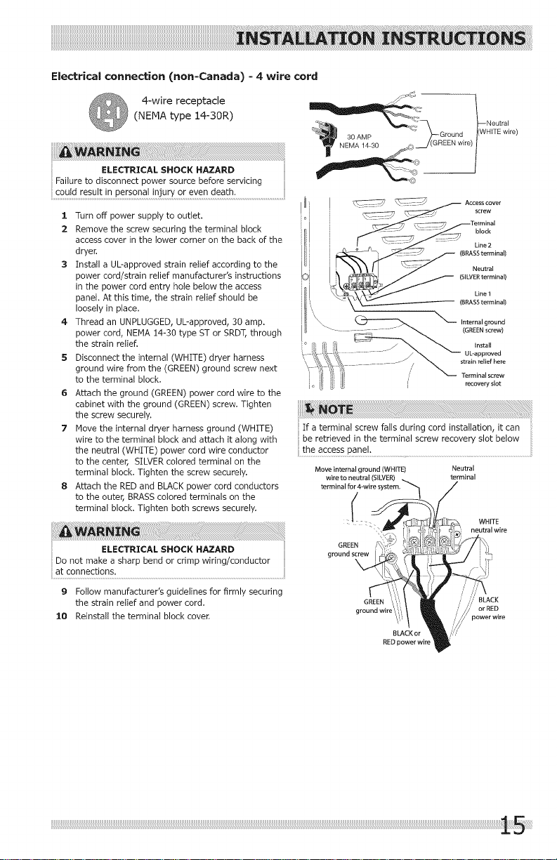
Electrical connection (non=Canada) = 4 wire cord
4-wire receptacle
(NEMA type 14-30R)
3. Turn off power supply to outlet.
2 Remove the screw securing the terminal block
access cover in the lower corner on the back of the
dryer.
3 Install a UL-approved strain retief according to the
power cord/strain relief manufacturer's instructions
in the power cord entry hole below the access
paneh At this time, the strain relief should be
loosely in place.
4 Thread an UNPLUGGED,UL-approved, 30 amp.
power cord, NEHA 14-30 type ST or SRDT,through
the strain relief.
5 Disconnect the internal (WHITE) dryer harness
ground wire from the (GREEN) ground screw next
to the terminal block.
6 Attach the ground (GREEN) power cord wire to the
cabinet with the ground (GREEN) screw. Tighten
the screw securely.
7 Nave the internal dryer harness ground (WHITE)
wire to the terminal block and attach it along with
the neutral (WHITE) power cord wire conductor
to the center, SILVERcolored terminal on the
terminal block. Tighten the screw securely.
8 Attach the RED and BLACKpower cord conductors
to the outer, BRASScolored terminals on the
terminal block. Tighten both screws securely.
ELEC'r.'CALS,oCK"AZAP,D
Donotmakeasbarpbendorcrimpwirhg/conductor
at connections.
9 Follow manufacturer's guidelines for firmly securing
the strain relief and power cord.
3.0 Reinstall the terminal block cover.
__ Acc_ cover
f_ black
Ifa terminal screw falls during cord installation, it can
be retrieved in the terminal screw recovery slot below
Line 2
(BRASS terminal)
Neutral
(SILVER terminal)
Line 1
(BRASS terminal)
-_ Internal ground
(GREEN screw)
Install
UL-approved
strain relief here
Terminal screw
recovery slot
the access panel. ...............
Move internal ground (WHITE)
wire to neutral (SILVER)
terminal for 4-wRe s
Neutral
terminal
{
neutral wire
GREEN
ground screw
\
GREEN
ground wit
BLACK
power wire
RED power wir
Page 16
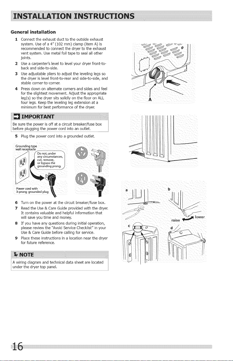
General installation
1 Connect the exhaust duct to the outside exhaust
system, Use of a 4" (102 mm) clamp (item A) is
recommended to connect the dryer to the exhaust
vent system, Use metal foit tape to seal all other
joints,
2 Use a carpenter's level to level your dryer front-to-
back and side-to-side,
3 Use adjustable pliers to adjust the leveling legs so
the dryer is level front-to-rear and side-to-side, and
stable comer-to-corner,
4 Press down on alternate corners and sides and feel
for the slightest movement. Adjust the appropriate
leg(s) so the dryer sits solidly on the floor on ALL
four tegs, Keep the leveling leg extension at a
minimum for best performance of the dryer.
5 Plugthe power cord into a grounded outlet.
..... I1receptacle
Power cord with
3:prong grounded plug
any circumstances,
_._ti,tea nce s' Icut ........
grounding prong.j_
6 Turn on the power at the circuit breaker/fuse box.
7 Read the Use & Care Guide provided with the dryer.
It contains valuable and helpful information that
wilt saveyou time and money.
8 If you have any questions during initial operation,
please review the "Avoid Service Checklist" in your
Use & Care Guide before calling for service.
9 Placethese instructions in a location near the dryer
for future reference.
Page 17
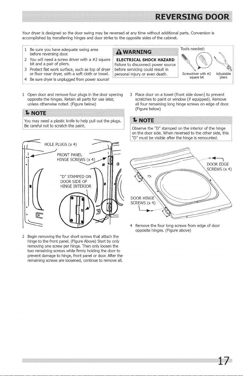
Yourdryerisdesignedsothedoorswingmaybereversedatanytimewithoutadditionalparts.Conversionis
accomplishedbytransferringhingesanddoorstriketotheoppositesidesofthecabinet.
I Be sure you have adequate swing area Tools needed:
before reversing door. _ _ %_,
2 You will need a screw driver with a #2 square ELECTRICAL SHOCK HAZARD _, ( \,_ } "*_, :i_
: bit and a pair of pliers. Failure to disconnect power source _,t,, _' ">- X_!_
3 Protect flat work surface such as top of dryer before servicing could result in
or floor near dryer, with a soft cloth or towel, personal injury or even death. Screwdriverwith #2 Adjustable
4 Be sure dryer is unplugged from power source! ......................................................................................................................................................squarebit pliers
! Open door and remove four plugs in the door opening 3 Place door on a towel (front side down) to prevent
opposite the hinges. Retain all parts for use later, scratches to paint or window (if equipped). Remove
unless otherwise noted. (Figure below) all four remaining long hinge screws on edge of door.
Be careful not to scratch the paint.
f--_2: HOLE PLUGS(x4) "D" must be visible after the hinge is remounted.
HINGE SCREW_
"D" STAMPEDON
DOOR SIDE OF
HINGE INTERIOR
2 Begin removing the four short screws that attach the
hinge to the front panel. (Figure Above) Start by only
removing one screw per hinge. Then only loosen the
two remaining screws while firmly holding the door to
prevent damage to hinge, front panel or door. After the
remaining screws are loosened, continue to remove all.
Observe the "D" stamped on the interior of the hinge
on the door side. When reversed to the other side, this
DOOR EDGE
SCREWS(x 4)
DOOR
SCREWS (x 4)
4 Remove the four long screws from edge of door
opposite hinges. (Figure above)
Page 18
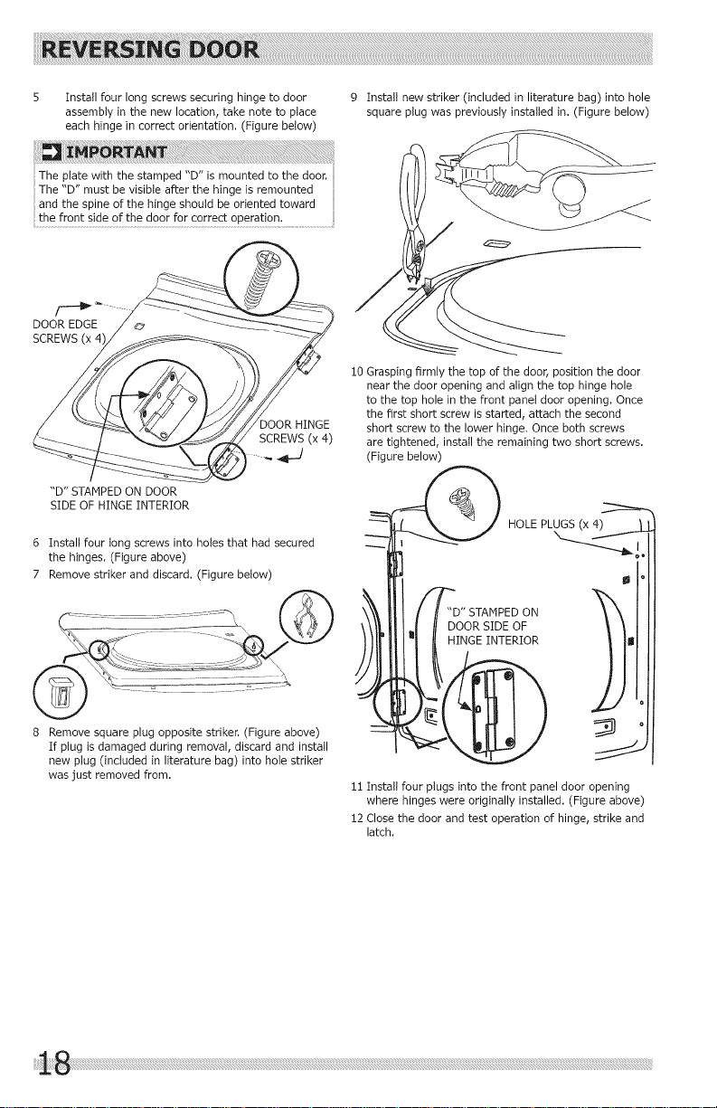
5 Installfourlongscrewssecuringhingetodoor
assemblyinthenewlocation,takenotetoplace
eachhingeincorrectorientation.(Figurebelow)
Theplatewiththestamped"D"ismountedtothedoor.
The"D"mustbevisibleafterthehingeisremounted
andthespineofthehingeshouldbeorientedtoward
thefrontsideofthedoorforcorrectoperation............
DOOREDGE
SCREWS(x4',
DOOR HINGE
SCREWS (x 4)
"D"STAMPEDONDOOR
SIDEOFHINGEINTERIOR
6 Install four long screws into holes that had secured
the hinges. (Figure above)
7 Remove striker and discard. (Figure below)
9 Install new striker (included in literature bag) into hole
square plug was previously installed in. (Figure below)
i0 Grasping firmly the top of the door, position the door
near the door opening and align the top hinge hole
to the top hole in the front panel door opening. Once
the first short screw is started, attach the second
short screw to the lower hinge. Once both screws
are tightened, install the remaining two short screws.
(Figure below)
HOLE PLUGS(x
8 Remove square plug opposite striker. (Figure above)
If plug is damaged during removal, discard and install
new plug (included in literature bag) into hole striker
was just removed from.
DOOR SIDE OF
HINGE INTERIOR
i! Install four plugs into the front panel door opening
where hinges were originally installed. (Figure above)
i2 Close the door and test operation of hinge, strike and
latch.
ON
Page 19

LP CONVERSION KIT
P/N PCK4200
Gas dryers intended for use in a location supplied with LP
must use a conversion kit prior to installation.
MOBILE HOME INSTALLATION KIT
P/N137067200
Installation in a mobile home requires the use of a
MOBILE HOME INSTALLATION KIT.
DRYING RACK (FOR USE WITH HODELS EQUIPPED
WITH MOISTURE SENSING BARS)
P/N137067300
Depending on the model you purchased, a drying rack
may have been included in the initial purchase of your
dryer. If your model did not include a drying rack or you
desire another drying rack, you may order one,
UNIVERSAL APPLIANCE WRENCH
P/N137019200
A UNIVERSAL APPLIANCE WRENCHis available to aid in
dryer/washer/pedestal feet adjustment,
TOUCH UP PAINT PENS*
Classic White Touch Up Pen - P/N 5304468812
_Other colors may be available. Contact the source where you
purchased your dryer.
Technical Sheet/Wiring Diagram:
A wiring diagram and technical data sheet are located
inside the dryer console.
To remove the console faceplate follow the directions
below:
1. Disconnect dryer from electrical source.
2. Remove the two screws toward the top on the back of
the console housing.
3. Insert a small screw driver through each hole on the
back of the console housing and gently press inward
to disengage each upper faceplate retaining tab.
4. Gently lay the console faceplate forward to access
technical/wiring diagram.
5. When finished with repair, return sheet inside console,
ensure lower retaining tabs are in place and snap
faceplate to upper retaining tabs. Reinsert the two
screws removed earlier.
approved by) the manufacturer could result in personal
TECH DATA SHEET/
Replacement parts:
Ifreplacementspartsareneeded foryourdryer,contact
the source where you purchased your dryer or refer to
your Useand Care Guide for more information. ELECTRICAL SHOCK HAZARD
Label all wires prior to disconnection when servicing
controls. Wiring errors cancause improper and dangerous
operation. Verify proper operation after servicing.
Page 20

Page 21

TABLE DES
Mesures de s_curit6 _mportantes .................. 22-23
Extgences d'lnstallatlon ................................. 24-30
Instrucbons d'mstallabon .............................. 31-36
MATIERES
Inversion de la porte .................................... 37-38
Accessolres ..................................................... 39
Remarques ...................................................... 40
Page 22

Pourvotres_curit6,l'informationcontenueclanscesinstructionsdoit_tresuivieafinder_duirelesrisquesd'incendieou
d'explosionoupourpr_venirtesdommagesmateriels,tesblessuresoulamort.Vousnedeveznientreposer,niutiliser
d%ssenceoud'autreSvapeursou!!quides!nfiammab!es_Rrgx!m!t_dece!appare!!oudetoutautreappare!!_lectrom_nager.
A AVERTISSEMENT
RISq D'I E
Lisez toutes les instructions de s_curit_ suivantes avant d'instalter et d'utiliser votre appareil :
• D_truisez le carton d'emballage et les sacs enplastique apr6s avoir dSball_ I'appareil. Les enfants pourraient les utile
ser pourjouer. Le carton recouvert de tapis, lescouvertures et lesfeuilles de plastique peuvent _tre 6tanches 5 Fair et
provoquer la suffocation. DSposeztousles matSriauxd'emballage dans un conteneur 5 dSchetsou faites en sorte que les
enfants ne puissent y avoir acc6s.
L'installation et I'entretien de cette s_cheuse doivent _tre r6alis_s par un instaltateur qualifi_, un technicien de
service ou le fournisseur de gaz.
Instaltez t'appareil conform_ment aux instructions du fabricant et aux codes Iocaux.
[_'installation _tectrique de la s_cheuse doit _tre conforme aux codes et aux rSglements Iocaux ainsi qu% ta toute
derni6re _dition du National Electrical Code (ANSI/NFPA 70), ou au Canada, au Code canadien de 1'61ectricit_
(C22.!, article i).
• [_'installation de gaz de ta s_cheuse dolt _tre conforme aux codes et aux r@glements tocaux ainsi qu% la route
derni@re_dition du Fuel Gas Code (ANSI Z223.:!), ou au Canada, au CAN/ACG B149.:!-2000. Un robinet d'arr%t
manuel distinct dolt @treinstalt_ 5 moins de !,83 m (6 pi) de la s@cheuseconform_ment au National Fuel Gas
Code, ANSI Z223.1/NFPA 54.
• La s@cheuseest ctass@e,envertu des r_glements ANSI Z 21.5.1 ou ANSI/UL 2158 - CAN/CSA C22.2 N° 112
(derni%resversions), pour un USAGEDOMESTIQUE uniquement. II n'est pas recommand_ d'utiliser cette s_cheuse
pour des usages commerciaux, comme des restaurants, des salons de coiffure, etc.
• N'installez pas une s_cheuse avec du mat@riel d'_vacuation en plastique ou en feuille m_taltique flexible. Le mat@-
riel de ventilation flexible peut s'_craser facilement et emprisonner la charpie. Ces conditions nuiraient 5 l'_coule-
merit d'air de votre s@cheuseet pourraient accro_tre le risque d'incendie.
• Les instructions comprises dans ce guide et route autre documentation fournie avec cet appareil ne sont pas
congues pour couvrir toutes les @ventualit@sou situations qui pourraient survenir. Vous DEVEZ faire preuve de bon
sens et de prudence durant I'installation, l'utilisation et l'entretien de tout appareil m@nager.
QUE FAIRE SI VOUS Dt_TECTEZ UNE ODEUR DE GAZ :
Ne mettez pas d'appareil en marche.
Ne touchez 5 aucun commutateur _lectrique; n'utilisez
aucun t_t_phone de votre domicile.
Evacuez ta piece, le bStiment ou ta zone touch_e.
En utilisant te t_l_phone d'un voisin, appetez immediate-
merit te fournisseur de gaz. Suivez ses instructions.
Sivous ne pouvez joindre votre fournisseur de gaz,
appelez les pompiers.
Pour #viter les blessures au dos ou d'autres types
de blessure, demandez l'aide d'autres personnes
pour d6placer ou soulever Ia s6cheuse.
Conservez ces instructions pour vous
y reporter uit rieurement,
Exigences avant I'installation
Outils et materiel n_cessaires &I'installation :
• Pince r#glable
• Tournevis Phillips _ pointe plate et
pointe carrie
• Cl_ _ molette
, Cl#_ tuyau pour I'atimentation en gaz
• Ruban _ filetage r_sistant au GPL
(pour I'alimentation en gaz naturet
ou en GPL)
Niveau de charpentier • Robinet d'arr_t pour conduite de
Event ext6rieur gaz (s6cheuse 5 gaz)
Conduit d'_vacuation de i02 mm (4 _ Deux raccords-unions 5 6vasement
po) en m_tal rigide ou semi-rigide de U2 po (i,3 cm) NPT et une
Ensemble pour cordon d'alimenta- gaz (s6cheuse 5 gaz)
tion de 240 V _ 3 ou 4 ills (s_cheu-
se _lectrique) • Ruban m_tallique (et non du ruban
Collier de 10,2 cm (4 po)
conduite flexible d'alimentation en
conduits)
Page 23

Veuitteztirecesinstructionsaucompletavantd'utiliser
les4cheuse.
Sachez reconnaitre lee symboles, les
avertissemen_s et les _tiquettes de
s_curit_.
Les mesures de s4curit4 pr_sent_es dans ce guide sont
identifi_es par te mot AVERTISSEHENT ou A_q-ENTION
selon le type de risque pr4sent_ ci-dessous.
D4finitions
Voici le symbole d'avertissement concemant la
s_curit_. II est utilis_ pour vous avertir des risques de
blessures potentiels. Respectez tous tes messages qui
suivent ce symbole afin de pr4venir les blessures ou la
mort.
La mention DANGER indique un risque imminent qui
causera la mort ou de graves blessures, s'il n'est pas
La mention AVERTISSEMENTindique une situation
potentietlement dangereuse qui, si elle n'est pas _vit_e,
situation potentiellement dangereuse susceptible de
causer des blessures mineures ou moyennement graves
sie!len%stpas_V!t_e..........................................................................................................
Conduit d'dvacuation
Lair circule librement, il n'y a aucune
accumulation de cbarpie
Le conduit rigide ou semi-rigide de 102 mm (4
po) est le plus court et te plus direct possible
[I n'y a AUCUN mat4riel de ventilation en papier
d'aluminium ou en plastique
Le syst4me d'_chappement dolt 4vacuer l'air a
I'ext4rieur a I'aide d'un 4vent approuve
Hise _ niveau
La s4cheuse est au niveau lat_ralement et de
I'avant vers l'arri_re
IZi Leequatre coins de la caisse reposent
fermement sur le plancber
Alimentationau gaz(sdcheuseaugaz)
lZi Le conduit d'alimentation comporte un robinet
d'arr&t manuel
lZi Tous lee raccords sont 4tancb4ifi4s 5 I'aide de
joints certifi4s serr4s avec une cl4
lZi N4cessaire de conversion pour syst_me au GPL
I_ L'alimentation en gaz est ouverte
r] Aucun raccord ne pr4sente de fuite -
v4rifiez 5 t'aide d'eau savonneuse, ne faites
]AHA_S cette v4rification avec une flamme
Alirnentation 41ectrique de 240 V (sdch, _lect)
lZi Le cordon d'alimentation est certifi4 NEHA i0-
30R ou i4-30R et it fix4 solidement avec routes
les vie clans le bornier
IZi Un r4ducteur de tension certifi4 est install4
IZi Le couvre-borne est install4 avant la premiere
mise en marche
:Inversion de la porte
iS1 Suivez tee instructions d4taiil_es contenues dane
ce guide
V4rifiez que la charni&re et le loquet
fonctionnent correctement
Alimentation en 41ectricit4
Le syst&me 41ectrique de la maison est sous
tension
IZi La s4cheuse est brancb4e
Vdrifications finales
Vous avez tu enti_rement tes instructions
d'instaiiation et le Guide d'utiiisation et
d'entretien
La porte se verrouilte et te tambour tourne
Iorsqu'un cycle d4marre
151 La carte d'enregistrement est envoy_e
Page 24

Exigences _lectriques de ia s_cheuse _lectrique:
CIRCUIT - Circuit ind_pendant de 30 amperes avec fusible temporis_ ou disjoncteur de 30 A, Utilisez des circuits
ind_pendants pour la laveuse et ta s_cheuse. NE BRANCHEZ PAS la laveuse et ta s_cheuse sur le m_me circuit.
ALIMENTATION teLECTRIQUE - C_ble monophas_ _ trois ou quatre ills, 240 volts, 60 Hz; courant altematifl
terre par le fit d'alimentation neutre.
PRISE - Prise NEMA I0-30R ou NEMA 14-30R situ_e de mani&re _ permettre I'acc&s au cordon d'alimentation Iorsque
ta s_cheuse est _ sa position de fonctionnement.
CONNEXION DE HISE A LA TERRE - Consuttez la rubrique <<Exigences de raise _ la terre >>dans la section
d'installation _lectrique,
TROUSSEDECORDON D'ALIMENTATION,_TROIS FILS
(non fournie)
Prise _ 3 alv&oles
(NEMA type 10-30R)
La s#cheuse DOIT utiliser un cordon d'alimentation
trois ills NEMA !0-30 de type SRDT d'une capacit# de
240 volts (c.a.) et d'au moins 30 amperes, avec trois
connecteurs ouverts embrochables avec extr#mit_s
renvers#es, ou connecteurs _ boucle ferm#e,
sp_cialement indiqu_s pour une utitisation avec une
s_cheuse. Pour les instructions de raccordement du
cordon _ 3 ills, consultez ia section CONNEXIONS
12LECTRIQUES POUR UN SYSTEME _, TROIS FILS.
TROUSSEDE CORDON D'ALIMENTATION ,_ QUATRE FILS
(non fournie)
Prise _ 4 alv&oles
(NEMA type 14-30R)
La s#cheuse DOIT utiliser un cordon d'alimentation
quatre ills NEMA i4-30 de type SRDT d'une capacit#
de 240 volts (c.a.) et d'au moins 30 amperes,
avec quatre connecteurs ouverts embrochables
avec extr#mit#s renvers#es, ou connecteurs
boucle ferm#e, sp_cialement indiqu#s pour une
utilisation avec une s#cheuse. Pour tes instructions
de raccordement du cordon _ quatre ills, consultez
la section CONNEXIONS teLECTRIQUES POUR UN
SYSTEME A QUATRE FILS.
Les s_cheuses destinies _ la vente au Canada sont
munies d'un cordon d'alimentation _ 4 fits (NEMA 14-
30R).
Page 25

E×igences _lectriques de la s_cheuse gaz
CIRCUIT - Circuit ind#pendant de i5 amp6res, polaris_
et mis _ la terre, avec fusible temporis# ou disjoncteur
de i5 A.
ALINENTATION I_LECTRIQUE- C_ble monophas_ _ deux
flls mis _ la terre, i20 volts, 60 Hz; courant alternatif,
CORDON D'ALINENTATION - La s_cheuse est dot#e d'un
cordon d'alimentation de i20 volts _ trois fils,
CONNEXION DE MISE A LATERRE - Consuttez la rubrique
<<Exigences de raise _ la terre >>dans la section
d'instaltation _lectrique,
Exigences relatives & I'alimentatiom en gaz
Un tuyau en cuivre sans rev&tement se corrode Iorsqu'il
entre en contact avec le gaz naturel, entra_nant des
fuites, Utilisez SEULEMENT des tuyaux en fer noir, en
acier inoxydable ou encore en cuivre avec rev&tement
i L'instaltation DOlT @tre conforme aux codes
2 Le tuyau d'alimentation en gaz dolt &tre d'un
3 Si les codes le permettent, un tuyau m@tallique
RISQUE D'EXPLOSION
Iocaux ou au code national sur te combustible,
ANSI Z223.! (derni@re version), s'il n'existe pas de
codes Iocaux.
diam&tre int_rieur de !,27 cm (!/2 po).
flexible peut @tre utilis_ pour raccorder votre
s@cheuse au tuyau d'alimentation en gaz. Le tuyau
DOIT @tre fabriqu_ en acier inoxydable ou en laiton
avec rev@tement en plastique.
Prisemurale avec
raise & la terre
iN/_ecoupez pas, n,enleve,_
,_ pas et ne mettez pas hors I
8circuit labroche de raise /
pm_ la terre de cette fiche. )
Cordon 61ectrk_uemuni _
d'unefiche _troisbroches_
ave=raise_la terre _,%
4 Le tuyau d'alimentation en gaz DOlT @tre muni d'un
robinet d'arr&t distinct conform_ment & la norme
B!49.!, Code d'installation du gaz naturel et du
propane.
5 Un orifice taraud@ de 0,32 cm (i/8 po) bouch_,
accessible pour le branchement de la jauge d'essai,
DOlT @tre install@ directement en amont du
branchement du tuyau d'alimentation en gaz avec
la s_cheuse.
6 Cette s_cheuse DOlT @tre d@branch_e de ta
canalisation de gaz pendant toute v@rification de
pression de la canalisation de gaz _ des pressions
sup_rieures & 3,45 kPa (!/2 tb/po2).
7 Cette s_cheuse DOlT @tre isol_e de la canalisation
de gaz pendant toute v@rification de pression de
la canalisation de gaz _ des pressions @gales ou
inf@rieures _ 3,45 kPa (i/2 Ib/po2).
8 Les branchements d'alimentation en gaz doivent
&tre conformes _ ta norme Connectors for Gas
Appliances (Raccords pour appareils au gaz) ANSI
Z21,24.
Page 26

E×igences du syst_rne d'_vacuation
Utilisez seutement des conduites m_taltiques rigides ou
flexibles d'au moins 10,2 cm (4 po) de diam&tre, et une
bouche d'_vacuation qui poss&de un ou des volets qui
s'ouvrent lorsque I'appareit est en fonction. Lorsque la
s_cheuse s'arr@te, les volets se ferment automatiquement
pour emp@cher les infiltrations d'air, d'insectes et de
rongeurs. Pour _viter de bloquer la sortie, gardez un
espace minimal de 30,5 cm (i2 po) entre le bas de la
bouche d'_vacuation et le sol ou toute autre obstruction.
Le non-respect de ces instructions pourrait augmenter
d_mesur_ment tes temps de s_chage et entra_ner des
risques d'incendie.
Vous trouverez ci-dessous les exigences pour l'uti =
lisation adequate et s_curitaire de votre appareiL
Iii__________________________!___;___Ji;;;;_?i iii¸
Correct
N'installez pas une s6cheuse avec du mat_riet
d'_vacuation en plastique ou en feuille m6tallique
flexible. Le materiel de ventilation flexible peut
s'_craser facilement et emprisonner la charpie. Ces
conditions nuiraient _ I'_coutement d'air de votre
s_cheuse et pourraient accro_tre te risque d'incendie.
Si votre syst&me actuel utilise une conduite en plastique
ou en feuille m_taltique, remplacez-la par une conduite
m_taltique rigide ou semi-rigide. De plus, assurez-vous
que la conduite en place est tibre de charpie avant
d'installer la conduite de s_cheuse.
RISQUE D'INCENDIE
incorrect
Page 27

E×igences de systb_e d°_vacuation (suite)
Une s6cheuse doit _tre _vacu6e vers Fext_rieur.
N'_vacuez pas une s_cheuse dans une chemin6e, un
mur, un plafond, un grenier, un vide sanitaire ou dans
tout espace dos d'un b_timent. La s_cheuse produit
de la charpie inflammable1 Si la s6cheuse n'est pas
6vacu6e vers I'ext_rieur, de la charpie pourrait _tre
6vacu6e dans I'aire de buanderie. L'accumulation de
charpie dans toute piece de ta maison peut entra_ner
des risques pour la sant_ et des risques d'incendie.
La s_cheuse dolt &tre branch_e _ une _vacuation
ext_rieure. Inspectez r6guti6rement Fouverture de
I'_vacuation ext_rieure et retirez toute accumulation de
charpie pr6s de Fouverture et de la r_gion avoisinante.
RISQUE D'INCENDIE
• Ne laissez pas de mati_re combustible (par
exemple : des v_tements, des rideaux, du papier)
entrer en contact avec le syst_me d'_vacuation.
La s_cheuse NE DOIT PAS_tre _vacu_e clans une
chemin_e, un mur, un plafond, ou dans tout espace
confin_ d'un b_timent qui pourrait accumuter la
charpie, entrainant un risque d'incendie.
• Ne placez pas degrillage _ I'extr_mit_ du syst_me
d'_vacuation, ni de vis, de rivet ou autre fixation
de mani&re _ ce qu'its se prolongent dans la
conduite du syst&me d'_vacuation. De la charpie
pourrait s'accumuter sur te grillage, les vis ou
les rivets, et obstruer 1'6coulement d'air dans
le syst&me, entrainant un risque d'incendie et
I'augmentation des temps de s6chage. Utilisez
une bouche d'_vacuation approuv_e pour terminer
la conduite _ t'ext_rieur, et scellez tousles joints
avec du ruban m_tallique. Toutes les extr_mit_s
m_les des conduites doivent &tre instalt_es en aval
ii
relativement au sensde I'_coulement d'air.
Le fait de d6passer la Iongueur de conduites ou te
:: ::nombre de coudes indiqu6s dans les tableaux de
<<LONGUEURMAXIMALE >>peut entrainer l'accumutation
de charpie clans le syst6me. Toute obstruction au
:: ::syst6me d'6vacuation peut entra_nerun risque
::d'incendie, en plus d'accro_tre le temps de s6chage.
LONGUEUR MAXIMALE
o_ pour le conduit en m_tal rigide de 10,2 cm (4 po)
9 TYPE DE BOUCHE D'EVACUATION
o-
0 19,5 m (64 pi) 14,6 m (48 pi)
1 15.9 m (52 pi) 12,2 m (40 pi)
2 13.5 m (44 pi) 9.8 m (32 pi)
3 11 m (36 pi) 7.3 m (24 pi)
4 9.5 m (28 pi) 4,9 m (16 pi)
(De pr_f6rence)
10 cm 6.5 cm
(4 po) _, volets (2.5 po)
* N'installez pas de materiel de ventilation en
plastique ou en aluminium flexible.
. Si vous installez du materiel de ventilation semi-
rigide, il est n_cessaire que la tongueur du conduit
soit _gale ou inf_rieure _ 2,4 m (8 pi),
Page 28

E×igences de syst_rne d'_vacuation (suite)
InstaHez les raccords m_les clans le bon sens :
CORRECT iNCORRECT
Pour une installation o3 le syst#me d'#vacuation n'est pas
d_crit dans tes tableaux, ta m_thode suivante doit _tre
utilis_e pour v#rifier la conformit# du syst_me :
1 Branchez un manom_tre 5 tube inclin_ ou un
manom_tre num#rique entre la s_cheuse et te point
o3 I'#vacuation est raccord_e 5 la s#cheuse.
2 R_glez la minuterie de la s_cheuse, ta temperature
duvetage (refroidissement), et mettez l'appareil
en fonction,
3 Relevez te r_suttat du manom_tre,
4 La contre-pression du syst#me NE DOIT PAS _tre
sup#rieure 5 19 mm (0.75 po) de colonne d'eau,
Si la contre-pression du syst_me est inf_rieure
19 mm (0,75 po) de colonne d'eau, te syst&me
est conforme. Si la lecture du manom_tre indique
une colonne d'eau sup_rieure 5 19 mm (0.75 po),
le syst_me est trop restreignant et n'est pas
conforme.
Bien que t'orientation verticale du syst_me d'#vacuation
soit acceptable, certaines circonstances pourraient influer
sur le rendement de t'appareil,
Seule une conduite m#tallique rigide doit _tre
utilis_e,
L'#vacuation verticale par le toit peut entra_ner
le ph_nom_ne de contre-tirage, ce qui accro_t la
restriction du syst_me d'_vacuation.
L'acheminement de la conduite d'_vacuation
dans un endroit non isol_ peut entra_ner de la
condensation et I'accumulation plus rapide de
charpie.
Le fait de comprimer ou de pincer le syst&me
d'_vacuation entra_nera t'augmentation de la
restriction dans te syst_me.
Le syst&me d'#vacuation doit _tre inspect# et
v#rifi# au moins tous les 18 mois avec un usage
normal. Plus I'appareil est utilis_, plus ta p_riode
de v#rification du syst_me et de la bouche
d'_vacuation doit _tre raccourcie,
Direction d'_vacuation
II est possible de diriger t'_vacuation en posant un coude
de 90° _ courbe immediate directement _ la sortie
d'6vacuation de la s_cheuse. Les coudes pour 6vacuation
de s6cheuse sont disponibles aupr&s du distributeur de
pi&ces de votre r6gion ou _ la quincaillerie.
Consultez #galement ta section EXIGENCES DE
DEGAGEHENT _ la page suivante,
L'utilisation d'un coude
90° _ courbe immediate
est n_cessaire pour
r_pondre aux exigences
de profondeur minimale
de la s_cheuse autonome.
Page 29

Installation darts une maison usin_e ou mobile
1 [_'installation DOIT _tre conforme _ ta norme
Manufactured Home Construction and Safety
Standard, titre 24 CFR, article 32-80 (anciennement
d_sign_e comme la Federal Standard for Mobile
Home Construction and Safety, titre 24, HUD,
article 280) ou _ la norme CAN/CSAZ240 MH.
2 La s_cheuse DOIT _tre _vacu_e vers I'ext_rieur
(_ I'air tibre et non sous la maison mobile) avec
une gaine m_tallique ininflammable. La conduite
m_taltique dolt poss_der un diam&tre de 10,!6 cm
(4 po) et ne contenir aucune obstruction. De
preference, utitisez une conduite m_taltique rigide.
3 Si la s_cheuse est _vacu_e par le plancher et que
I'espace sous la maison mobile est cloisonne, le
syst&me d'_vacuation DOIT se terminer _ I'ext_rieur
de la cloison et _tre fix6 solidement _ la structure
de la maison.
4 Reportez-vous aux sections pr6c_dentes de
ce guide retativement aux autres exigences
d'6vacuation importantes.
5 Lors de I'installation d'une s_cheuse _ gaz dans
une maison mobile, des dispositions doivent _tre
prises pour permettre t'entr_e d'air d'appoint de
l'ext_rieur. Cette installation ne dolt pas mesurer
moins de deux lois la surface de la bouche
d'6vacuation.
6 L'installateur DOIT ancrer cette s_cheuse au sol
avec une trousse d'installation de maison mobile,
n° de piece 137067200.
Installation darts un Endroit en Retrait ou une Armoire
1 Une s#cheuse instalt#e dans une chambre
coucher, une salte de bains, un renfoncement ou un
placard DOIT _tre #vacu#e vers I'ext_rieur.
2 Aucun autre appareil _ combustion ne doit &tre
install# dans le m_me placard que la s_cheuse.
3 Votre s_cheuse a besoin d'espace pour assurer une
ventilation ad#quate.
N'INSTALLEZ PAS votre s#cheuse dans un placard muni
d'une porte pleine
a, Porte de placard assurant une ventilation requise :
Une ouverture d'au moins 774,2 cm2 (120 po2),
divis#e #galement au-dessus et au-dessous de
la porte, est requise. Les ouvertures doivent _tre
situ_es _ 7,6 cm (3 po) du haut et du bas de la
porte. Les ouvertures ne doivent pas _tre obstru_es
Iorsqu'une porte est instalt_e. Une porte
persiennes dont les ouvertures sur I'ensemble de la
porte sont _quivalentes aux recommandations peut
&tre utilis_e.
Page 30

Exigences de d_gagement
N'INSTALLEZ PAS VOTRE SECHEUSE :
:t A un endroit expos_ aux &oulements d'eau
ou aux alias des conditions m@_oro!ogiques
ext_rieures.
2 A un endroit o0 elle entrera en contact avec
des rideaux ou tout autre objet qui nuirait
I'_coutement de I'air de combustion ou de
ventilation.
3 Sur un tapis, Le plancher DOIT &tre solide et
presenter une pente inf_rieure _ 2,5 cm (i po).
DEGAGEMENTS MINIMAUX - Pouces (Centim&tres)
C6TES ARRIERE DESSUS AVANT
AIc6ve O" (0 cm) O" (O cm)* 23" (58.5 cm) n/a
Placard 0" (0 cm) 0" (0 cm)* 23" (58,5 cm) 1" (2.5 cm)
Pour toute installation autre qu'une _vacuation
directe, un coude de 90° _ courbe immediate dolt
@tre utilis_ pour respecter I'exigence de 0 cm (0 po),
o....
(0 cm) (00cm)
1" 0"
(2.5 cm) (0 cm)
N'installezpas la s&heuse i_o_ de l'essenceou autres
RISQUED;EXPLosioN
mati_res inflammables sont entrepos_es. Si la s_cheuse
est instalt_e dans un garage, elle dolt 6tre plac6e au
moins _ 45,7 cm (!8 po) du sol, Le non-respect de cette
recommandation peut entra_ner un choc _tectrique, une
explosion,unincendieoum_melatoo..
Dimensions de S_cheuse
I_ 2T' (68,5 era)
38.5"
(98 cm)
42.5"
(108 cm)
(9.s0_)"'-_1_
Duc6t@jusqu'au
centrede I'@ventarri@re
LonguecN du co_do_ d'alimentation de la s&heuse & ciaz, environ _52,S cm (6O po)
gaz _ rarriere de
Alimentation en
I'appareil & gaz
(34,5 cm)
AEimentation
@tectrique
rarn&re de la
_@cheuse _
....
Hauteur de la
ligne centra_e
de r@vent ard&re
Pour obtenir une installation avec un d_gagement
de 0 cm (0 po) _ t'arri&re de ta s_cheuse (pour une
installation autre qu'avec une sortie directe), un coude
de 90° _ courbe immediate dolt &tre install6, comme il
est d6crit pr_c6demment dans ce guide.
_(9 !5?c'm) P{ancher
50" (127 cm)
29"(73,5 cm)
Jorsqu'eHe estferm@e
po_e
ii!i!i!3 i!0 ........................................................................................................................................................................................................................................................................................................................................................................................................................................................iill
Page 31

Installation _lectrique
Vous trouverez ci-dessous les exigences pour t'installation
#lectl,ique ad#quate et s#cul,itaire de votre appareit. Le
non-l,espect de ces instructions poul,rait entra_ner le
risque de choc ou d'incendie.
RISQUE DE CHOC ELECTRIQUE al,rach# de t'appareil ou coup# pal, tout mouvement,
Cet appal,eil DOIT &tl,e ad#quatement mis _ la ce qui entra_nerait un risque de choc #lectrique.
ii i.
tel're. La mise _ la tel're inad#quate de la s_cheuse _ N'utilisez pas une prise avec c_blage en aluminium
• Un r#ducteul, de tension certifi# UL doit &tre install#
sul, te cordon d'alimentation. Site r#ducteur de
tension n'est pas installS, le cordon peut &tre
pourl,aitentl,a_nel,desl,:squesdechoc_lectl,ique. aveconcordond'alimentationetuneficheavecfils
Suivez les instructions de ce guide pour une mise _ en cuivl,e (ou I'invel,se). Une l,_action chimique se
ta tel're ad#quate, pl,oduit entre I'aluminium et le cuivre, ce qui pourrait
N'utilisez pas de rallonge avec cet appal,eil. Certains entra_ner un court-circuit. It faut utiliser un cordon,
ii_i"
cordons pl,o!ongateul,s ne sont pas con_us pour ....................................................................................................................................................................................
la quantit_ de coul,ant #lectrique utitis# pal, cette
s_cheuse et pourl,aient fondre, entl,a_nant des
risques de choc _lectl,ique ou d'incendie. Placez la
s_cheuse _ une distance de la prise convenant _ .... Les s_cheuses aliment_es pal, une tension de 208 V
la tongueul, de la l,allonge, pel,mettant d'installel, la poss#deront des temps de s#chage plus longs qu'une
rallongeI_chement.Reportez-vousauxexigencesde s_cheuseatimentaeparunetensionde240V.
pr_instaltation de ce guide pour savoir quel cordon
: d'atimentation acheter.
E×igences de raise & la terre - S_cheuse _lectrique (E,-U,)
une fiche et une prise avec des ills en cuivre.
:Un raccordement inad_quat du conducteur de mise _ la
terl,e de I'_quipement peut accro_tl,e les risques de choc
_lectrique. En cas de doute quant _ la mise _ la terre
de I'appareit, consultez un _lectricien quatifi_.
Pour une s_cheuse avec cordon, mise _ la tel,re :
:1. Cet appareit DOIT _tre mis _ la terl,el En cas de
mauvais fonctionnement ou de panne, la mise
la terl,e diminue les risques de choc _tectrique en
fournissant au courant _lectl,ique une trajectoire de
moindl,e r_sistance.
2 Apr_s I'achat et I'instaltation d'un cordon
d'alimentation _ 3 ou 4 ills dot_ d'un fil de mise
la tel're et d'une fiche de mise _ la terre qui
correspond & votre syst@me de c_blage, la fiche
DOIT @tre branch@e dans un r@ceptacle cuivr@
install@ et mis _ la terre conform@ment aux codes
et r@glements locaux. En cas de doute, faites appel
un @lectricien qualifi@.
NE MODIFIEZ PAS ta fiche fournie avec cet
appareil. Si elle ne s'ins@re pas dans la prise,
demandez _ un @lectricien qualifi@ d'installer la
prise adapt_e.
Pour
une s_cheuse avec branchement permanent :
1
La s_cheuse DOIT _tre branch_e _ un syst&me de
c_bles m_taltiques permanents mis _ la terre; ou un
conducteur de mise _ la terre dolt &tre install_ avec
les conducteurs de circuit et branch_ _ la borne ou
au fil de mise _ la terre de l'appareil.
Page 32

E×igences de raise & la terre =S_cheuse _lectrique (Canada)
2 Puisque votre appareit est muni d'un cordon
d'alimentation avec filet fiche de raise _ la terre,
Un raccordement inad6quat du conducteur de raise _ la terre
de J'6quipement peut accroTtre Jes risques de choc _Jectrique.
En cas de doute quant _ la raise _ la terre de I'appareiJ,
consuJtez un 61ectricien quaJifi6.
Pour une s_cheuse avec cordon, mise _ la terre :
1 Cet appareil DOIT _tre mis _ ta terre. En cas de
mauvais fonctionnement ou de panne, ta raise
la terre diminue les risques de choc _lectrique en
fournissant au courant _lectrique une trajectoire de
moindre r_sistance.
la fiche dolt _tre branch_e dans un r_ceptacle
install_ et mis _ la terre conform_ment aux codes
et r&glements locaux. En cas de doute, faites appel
un _lectricien qualifi_.
3 NE IqODIFIEZ PASta fiche fournie avec cet
appareil. Si elle ne s'ins_re pas dans la prise,
demandez _ un _lectricien qualifi_ d'installer la
prise adapt_e.
Exigences de raise _ la terre =S_cheuse _ gaz (E,=U. et Canada)
1 Cet appareit est muni d'une fiche _ trois broches
(raise _ la terre) pour assurer votre protection
contre les chocs _tectriques, Cette fiche doit &tre
branch_e directement dans une prise _ trois
alv_oles correctement raise _ ta terre.
2 La fiche dolt _tre branch_e dans un r_ceptacle
install6 et mis _ la terre conform_ment aux codes
et r&glements Iocaux, En cas de doute, faites appel
un _lectricien qualifi_.
3 NE IqODIFIEZ PASta fiche fournie avec cet
appareit. Si etle ne s'ins&re pas dans la prise,
demandez _ un 61ectricien quaiifi6 d'installer la
prise adapt_e.
Prise murale avec
raise _ la terre
jpas et ne mettez pas hors
._ circuit la broche de mise
(N.... pez pas, n'enleve_
rre de cette fiche.,
Page 33

Connexion de gaz
1 Retirez te capuchon d'exp_dition de la conduite de
gaz _ i'arri&re de !'appareil.
NE RACCORDEZPAS la s_cheuse _ une alimentation
en propane liquide sans avoir pr_alablement converti la
soupape de gaz. Le n_cessaire de conversion au propane
!!qu!de doit _tre !nsta!!_ par un techn!den qua!!fi_ ................................
2 Branchez un tuyau semi-rigide ou approuv_ d'un
diam&tre int_rieur de 1,27 cm (1/2 po) de la
conduite d'alimentation de gaz au tuyau de 0,96 cm
(3/8 po) situ_ _ t'arri&re de I'appareil. Utilisez un
r6ducteur de 1,27 cm _ 0,96 cm (1/2 po _ 3/8 po)
pour effectuer te raccordement. Utilisez du ruban
d'_tanch_it_ r6sistant _ I'action corrosive des gaz
I'_tat liquide _ chaque raccord.
ECOULEMENT
Robinet Raccord- _ Raccord-
d'arr_t union _ union
manuel _vasement _vasement
DU GAZ
30uvrez le robinet d'arr_t dans la conduite
d'alimentation de gaz pour permettre au gaz de
s'_couler dana te tuyau. Attendez quetques minutes
pour que le gaz s'_coule dana la conduite.
Robinet d'arr_t
en position ouverte
4 V_rifiez le syst_me avec un manom&tre pour
d_celer toute fuite. Si vous n'avez pas de
manom&tre, v_rifiez tes raccords en appliquant de
I'eau savonneuse sur les connexions.
flexible raccord_ _ I'arri_re
Tous les raccords doivent _tre serr_s au moyen d'une el&
de la s_cheuse
La conduite d'atimentation dolt &tre munie d'un robinet
d'arr_t approuv_. Ce robinet dolt &tre situ_ dana la
m&me piece que la s_cheuse et plac_ de mani_re
&tre facilement accessible. Ne bloquez pas I'acc_s au
robinet d'arr&t de t'atimentation de gaz.
Nev_rifiez ]AMAIS la presencede fuites _ I'aided'une
flamme nue.
Page 34

Connexion_lectrique(saufau Canada) = cordon & 3 ills
Prise _ 3 alv_oles
(NEMA type 10-30R)
Le fair de ne pas d#brancher t'appareil de sa source
d'alimentation en #lectricit# avant son entretien peut
causer des blessures, voire la mort.
1 Coupez I'alimentation _ la prise.
2 Retirez ta vis qui fixe le couvercle d'acc&s du bornier
darts le coin inf_rieur du dos de la s_cheuse.
3 [nstallez un r_ducteur de tension certifi6 UL
conform_ment aux instructions du fabricant de
cordon d'alimentation ou de r6ducteur de tension
darts I'orifice de cordon d'alimentation sous te
panneau d'acc_s./_ ce moment, te r6ducteur de
tension devrait &tre instatt_ l_chement,
4 Passezun cordon de 30 A certifi_ UL NENA 10-30
de type SRDT,NON BRANCHIa,dans le r6ducteur de
tension.
5 Fixez tefil neutre du cordon d'alimentation (ill du
centre) _ ta borne centrale ARGENT du bornier.
Serrez bien tavis.
6 Fixez tesdeux autres ills aux bornes externes en
LAITON du bornier. Serrez bien les deux vis.
Si une vis de borne tombe pendant l'installation du
F[] 1
LAITON)
LAITON)
N'effectuez pas de courbe soudaine, et ne pincez pas le
c_blage ou les conducteurs aux connexions.
7 Suivez tesconsignes du fabricant pour fixer
solidement le r_ducteur de tension et le cordon
d'alimentation.
8 R_installez le couvercle du panneau d'acc6s au
bornier.
Si vous passez d'un syst&me 5 quatre ills 5 un syst&me
trois ills, d_placez le fil de mise 5 ta terre interne de
la borne centrate du bornier 5 la vis VERTE5 c6t_ du
bornier.
N'ENLEVEZ PAS la raise
la terre interne dans neutre
un syst6me &trois ills]
Borne
Page 35

Connexion _ledcrique (sauf au Canada) - cordon & 4 fils
Prise _ 4 alv&oles
(NEMA type 14-30R)
_9--/ (Fils VERTS)
Le fait de ne pas d#brancher t'appareil de sa source
d'alimentation en #lectricit# avant son entretien peut
causer des blessures, voire la mort.
1 Coupez I'alimentation _ la prise.
2 Retirez ta vis qui fixe le couverde d'acc&s du bornier
dans le coin inf_rieur du dos de la s_cheuse.
3 [nstallez un r_ducteur de tension certifi_ UL
conform_ment aux instructions du fabricant de
cordon d'alimentation ou de r_ducteur de tension
dans I'orifice de cordon d'alimentation sous te
panneau d'acc_s. Ace moment, te r_ducteur de
tension devrait &tre instatt_ l_chement.
4 Passezun cordon de 30 A certifi_ UL NENA 14-30
de type SRDT,NON BRANCHt--',clans le r6ducteur de
tension.
5 D_branchez te fil de mise _ laterre du faisceau
_lectrique interne de la s_cheuse (BLANC)de la vis
de raise _ la terre (VERTE) pros du bornier.
6 Fixez tefil de raise _ ta terre (VERT) du cordon
d'alimentation _ la caisse avec la vis de mise _ la
terre (VERTE). Serrez bien la vis.
7 D_placezle fil de raise_ laterre du faisceau
_lectrique interne (BLANC) au bornier et fixez-te avec
le fil neutre du cordon d'aiimentation (BLANC) _ la
borne centrale ARGENTdu bornier. Serrez bien la vis.
8 Fixez tesfils ROUGEet NOIR du cordon
d'alimentation aux bornes externes en LAITON du
bornier. Serrez bien les deux vis.
Si une vis de borne tombe pendant l'installation du
cordon, elle peut &tre r_cup_r_e dans la fente de
r_cup_ration sous te panneau d'acc&s.
Darts un syst_me _ 4 ills, bi'anchez
le fil de raise & laterre interne (BLANC) ._
zsur la borne neutre (ARGENT). /
Fils neutres
(Fiis BLANCS)
Borne
neutre
N'effectuez pas de courbe soudaine, et ne pincez pas le
c_blage ou les conducteurs aux connexions.
9 Suivez lesconsignes du fabricant pour fixer
solidement le r_ducteur de tension et le cordon
d'alimentation.
10 R_installez le couvercle du panneau d'acc&s au
bornier.
Visdemise /_ i' i
BLANC
_la terreV_ _:
la re,re VERT
Page 36

Installation (g_n_rale)
1 Branchez la conduite d'6vacuation au syst_me
d'#vacuation ext_rieur L'utitisation d'un collier
(pi&ce A) de !02 mm (4 po) est recommand_e pour
raccorder ta s_cheuse au syst&me d'#vacuation.
Utilisez du ruban m_tallique pour sceller les autres
joints.
2 Utilisez un niveau _ butte pour mettre I'appareil
niveau de l'avant vers I'arri&re et lat#ralement.
3 Utilisez tacl# universelle pour ajuster tes pieds de
mise _ niveau de faqon _ ce que la laveuse soit de
niveau d'avant en arri&re et tat#ralement, et qu'elle
soit stable aux quatre coins.
4 Appuyez sur chaque coin et chaque c6t# pour
d#terminer les endroits qui n_cessitent un r#glage.
Ajustez les pieds de mise _ niveau appropri#s de
mani&re _ ce que la taveuse repose solidement
sur ses QUATRE pieds. Gardez les pieds de mise
niveau te ptus pr&s possible de ta laveuse afin
d'optimiser le rendement de la s_cheuse.
5 Branchez le cordon d'alimentation _ la prise
_lectrique mise _ la terre.
i_ i_ i i i i i i
b
60uvrez t'alimentation _lectrique au disjoncteur ou
au bottler de fusibles.
7 Reportez-vous au Guide d'utilisation et d'entretien
fourni avec la s_cheuse. II contient des
renseignements trSs utiles qui vous permettent
d'_conomiser temps et argent.
8 Pourroute question relative 5 l'utilisation initiale,
veuillez vous reporter 5 la section <<Liste de
v_rification >7de votre Guide d'utitisation et d'entretien
avant d'effectuer une demande de service.
9 Laissez ces instructions 5 proximit_ de la s_cheuse
pour vous y reporter utt_rieurement.
Un schema _tectrique et une fche technique sont
situ_s _ I'int_rieur de ta console de I'appareit.
soui!_ er
Page 37

La s_cheuse est concue de fa_on que t'ouverture de la porte puisse _tre invers6e entout temps sans pi_ces
additionnelles. L'inversion de [a porte requiert [e transfert des charni_res au c6t_ oppos_ du chassis,
i Assurezvous0u'i,yosu, sommeoi;e :: n
: avant d'inverser la porte. _ _ _
2 Vous aurez besom d'un tournews a po_nte RXSQUE BE ¢HO¢ ELECTRXQUE _, I: _\_',, _ x_ti_
carr6e n° 2, Le fait de ne pas d6brancher :":," _: _'_
3 Prot6gez la surface de travail comme ledessus 'appare de sa source "_ "_
de ta s6cheuse ou te plancher prosde ta d'alimentation en _tectricit_ avant Tournevis avec Pince
s&:heuse, avec un chiffon doux ou une serviette, son entretien peut causer des embout..... 6 no2 r6glable
4 Assurez-vous que la s6cheuse n'est pas btessures, voire ta mort.
branch6e _ une source d'atimentation!
10uvrez la porte et retirez tes quatre bouchons situ6s
darts t'ouverture de la porte oppos6e aux charni6res,
A moins d'indication contraire, conservez toutes tes
pi&ces pour tes r6utiliser plus tard, (Voir l'illustration
ci-dessous,)
Un couteau _ mastic en plastique peut s'av_rer
n6cessaire pour retirer tes bouchons. Prendre soin de La tettre<< D >>est grav_e _ t'int6rieur des charni&res
ne pas _gratigner la peinture, du c6t6 de la porte. Lorsque vous inverserez ta porte,
__.._...._ BOUCHONS (x 4)
IT_--_DES CHARNIERESDU
PANNEAUAVANT (x 4)
LALE]q-RE <<D >>DOIT
APPARAITREA L'INTE-
RIEUR DE LA CHAR-
NITRECOT_ PORTE
2 Enlevez d'abord les quatre petites vis qui retiennent
la charni6re au panneau avant. (Voir I'iltustration ci-
dessus) Pour facititer l'op6ration, retirez tout d'abord
une seule vis par charni&re. Desserrez ensuite les deux
vis restantes tout en tenant fermement ta porte pour
_viter d'abfmer tes charni6res, le panneau avant ou
la porte. Une fois les vis desserr_es, retirez les vis qui
restent.
Placez ta porte sur une serviette (c6t6 avant contre te
sol) pour _viter d'6gratigner ta peinture ou ta fen6tre
(le cas _ch6ant). Enlevez tes quatre grandes vis qui
retiennent tescharni_res 5 la porte (Voir I'illustration
ci-dessous.)
assurez-vous de revisser tescharni6res de fa_on _ ce
que le D >>soit visible,
VIS DU REBORD
DEXLAPORTE (x 4)
VIS DES
DE LA PORTE
4 Retirez lesquatre grandes vis de la porte situ6es du
c6t6 oppos_ des charni_res (voir I'illustration ci-dessus),
Page 38

_,t'aidedequatregrandesvis,fixeztescharni_res
laportedanslestrousduc6t6oppos6,Assurez-vous
d'orientertescharni_resdanslabonnedirection(voir
t'illustrationci-dessous),
La plaque marquee d'un <<D >>dolt _tre fix#e du c6t_ de
la porte. Ce <<D >>dolt _tre visible apr_s avoir reviss_ les
charni_res et le dos des charni_res dolt #tre orient# vers
le c6t_ avant de la porte pour que cette derni_re puisse
fonctionner correctement.
VIS DU
DE LA PORTE (
PORTE(x 4)
LA LE]_RE <<D >>DOIT APPARAITRE A L'IN-
T_RIEURDE_ CHARNIEREC6T_PORTE
6 Instaliez quatre grandes vis dans tes trous qui
servaient _ fixer les charni_res (voir I'illustration
ci-dessus),
7 Enlevez la g_che et jetez-ia, (Voir I'illustration ci-
dessous,)
9 Instaltez une nouvelle g_che (incluse dans te sac
contenant le manuet d'utilisation) dans le trou qui
contenait le bouchon carr# que vous avez retir_ (voir
I'illustration ci-dessous),
10 En tenant fermement le haut de ta porte, positionnez-
la pros de I'ouverture et alignez te trou de ta charni_re
sup#rieure sur te trou sup_rieur du panneau avant
de t'ouverture de porte. Une fois ta premiere petite
vis engag_e, fixez la deuxi_me vis dans ta charni_re
inf_rieure, Apr_s avoir serr_ tes deux vis, fixez et
serrez tes deux derni_res petites vis (voir I'illustration
ci-dessous),
BOUCHONS(x 4)_1.1
LALETFRE _ D _ DOIT
APPARAITRE A UINTE-
RIEUR DE LACHARNIERE
C6T_ PORTE
8 Enlevez te bouchon carr6 de la g_che du c6t_ oppos6
(voir t'illustration ci-dessus), Placez le bouchon dans
le trou de ta gSche que vous venez d'enlever (si vous
endommagez le bouchon tors de son retrait, jetez-le et
utilisez le bouchon de rechange inclus clans le sac du
manuel d'utilisation),
11Ptacez quatre bouchons dans tes trous du panneau
avant de ta porte _ I'endroit oO les charni_res _taient
plac_es avant t'inversion. (Voir l'iltustration ci-dessus,)
!2 Fermez la porte et v_rifiez te fonctionnement de la
charni_re, de la gSche et du Ioquet.
Page 39

NECESSAIRE DE CONVERSION AU GPL
PIECE N ° PCK4200
Les s_cheuses _ gaz qui seront utilis_es dans un endroit
aliment_ par du propane liquide doivent recourir 5 un
n_cessaire de conversion avant l'installation.
TROUSSE D'INSTALLATION DE MAISON MOBILE
PIECE N° 137067200
Toute installation darts une maison mobile n_cessite
I'utilisation d'une TROUSSE D'INSTALLATION DE MAISON
MOBILE.
ETAGERE DE SECHAGE (POUR UTILISATION AVEC
MODELES MUNI DES BARRES HYGROSTAT)
PIECE N ° 137067300
Selon le mod_le que vous avez achet_, ilse peut qu'une
_tag_re de s_chage ait_t_ inclusedans l'achatinitial
de votre s#cheuse, Sivotre mod#le ne comprenait pas
d'6tag_rede s6chage ou que vous en d_sirezune autre,il
vous est possibled'en commander une.
CLE D'APPAREIL UNIVERSELLE
PIECE N ° 137019200
UNE CLE D'APPAREIL UNIVERSELLE est offertepour
faciliter le r6glage des pieds de s_cheuse/taveuse/socle,
CRAYONS DE PEINTURE DE RETOUCHE _
Crayon de retouche Blanc - PIECE N ° 5304468812
*II se peut que d'autres couleurs soient disponibles. Communiquez
avec lemarchand qui vous a vendu votre s_cheuse.
Fiche Technique/Schema Electrique:
Un sch6ma 61ectrique et une fiche technique sont
situ6s _ I'int6rieur de ta console de I'appareit.
Pour enlever la plaque avant de la console, suivez les
instructions ci-dessous :
I, D6branchez la s6cheuse de sa source d'alimentation
en _tectricit_.
2. Retirez les deux vis situ6es dans le haut de I'arri&re du
chassis de la console.
3. Ins6rez un petit tournevis dans chacun des trous
situ_s _ t'arri&re du chassis de la console et appuyez
doucement vers l'int_rieur pour d_sengager l'onglet de
r_tention de la plaque avant.
4. D_posez doucement la plaque avant de la console
pour acceder _ la fiche technique et au sch6ma
_lectrique,
5, Une fois la r_paration termin_e, remettez la feuille
l'int_rieur de la console, assurez-vous que les ongtets
de r6tention inf6rieur sont en place et enclenchez la
plaque avant aux onglets de r_tention sup_rieurs,
R_ins_rez tes deux vis que vous avez retirees
pr_c_demment.
b!essu!es de d ommage au bien o I s#cheuseT
FICHE TECHNIQUE/
ELECTRtQUE
Pi_ces de rechange :
Si vous devez commander des pi_ces de rechange
pour votre s_cheuse, communiquez avec le
marchand qui vous a vendu votre appareil, ou
reportez-vous au guide d'utilisation et d'entretien
pour obtenir plus de d_tails.
t_tiqueteztous RISQUE ELECTRIQUE
des commandes. Deserreurs de c_blage pourraient nuire au bon
fonctionnement de l'appareil, et m_me &tredangereuses. V6rifiez
les ills avant de les d_brancher pendant t'entretien
tebon fonctionnement de t'apparei! apr_s tout entretien.
Page 40

Page 41

[NDICE
Instrucciones importantes de segurldad ......... 42-43 Inversl6n de la puerta ................................... 57-58
Requls[tos de instalacl6n ............................... 44-50 Acceso_os ....................................................... 59
Instrucciones de instalacl6n .......................... 51-56
Page 42

Parasuseguridad,debeseguirlainformaci6ndeestagu[aparaminimizarelriesgodeincendiooexplosi6nopara
evitardaflosalapropiedad,tesionespersonalesoinclusotamuerte.NoalmaceneniutilicegasolinaniotrosI[quidos
ovaporesinflamabtescercadeesteodecuatquierotroelect!odom_stico..........
ADVERTENCIA
PE GRO DE INCENDIO
Lea las siguientes instrucciones antes de instalar y utitizar este electrodom_stico:
* Despu_s de desembalar la secadora, destruya los cartones y las bolsas de plastico. Los ni_os podrfan utilizarlos para
jugar. Los cartones cubiertos con alfombras, cubrecamas, o laminas de plastico pueden convertirse en camaras de aire
herm_ticamente cerradas y provocar asflxia. Coloque todos los materiales en un basurero o mant_ngalos fuera del
alcance de los ni_os.
* La instalaci6n y el servicio de la secadora de ropa deben ser ltevados a cabo por un instalador calificado, agencia
de servicios o proveedor de gas.
* Instale la secadora de ropa de acuerdo con las instrucciones del fabricante y los c6digos locales.
* La reparaci6n el_ctrica de la secadora debe cumplir con los c6digos y las ordenanzas locales y ta Oltima edici6n del
C6digo Et_ctrico Nacional (National Electrical Code), el ANSI/NFPA 70, o bien en Canada, el CSAC22.1 del C6digo
El_ctrico de Canada (Canadian Electrical Code) Parte i.
* Elservicio de gas de ta secadora debe cumplir con los c6digos y lasordenanzas locales, y ta Ottima edici6n del
C6digo de Gas Nacional (National Fuel Gas Code), el ANSI Z223.1, o bien en Canada, el CAN/CGA B149,I-2000.
* La secadora se dise_6 conforme a los c6digos ANSI Z 21.5.1 o ANSI/UL 2158 - CAN/CSA C22.2 N.o 112 (0ttimas
ediciones) solo para USODOIVlESTICO.No se recomienda esta secadora para uso comercial, como por ejemplo, en
restaurantes, salones de belleza, etc.
* No utilice materiales de ventilaci6n de pl_stico ni de papel de aluminio flexibles para instalar la secadora de ropa.
Por Io general, dichos materiales se desarman, se deterioran con facitidad y acumulan pelusa. Estas condiciones
obstruyen el flujo de aire de la secadora y aumentan el riesgo de incendio.
* Las instrucciones de esta gu[a y todo el material que se incluye con esta secadora no tienen como prop6sito cubrir
todas las condiciones y situaciones que puedan presentarse. Cuando instale, opere o repare cuatquier artefacto
DEBEtener cuidado y hacer uso de buenas practicas de seguridad.
QUI_ HACER SI SIENTE OLOR A GAS:
• No intente encender ning0n electrodom_stico.
• No toque ning0n interruptor el6ctrico; no utilice
ning0n tel6fono en la vivienda.
• Despeje la habitaci6n, el edificio o el _rea de todos
los ocupantes.
• Llame inmediatamente a su proveedor de gasdesde
el tel6fono de un vecino. Siga las instrucciones del
proveedor de gas.
• Si no puede ponerse en contacto con el proveedor de
gas, llame a los bomberos.
Para evitar lesiones en la espalda u otro tipo de
lesiones, procure tevantar o mover la electrodom_stico
_°n!aaYudadem_sdeunaPers°na:..............................................................................
Conserve estas instrucciones para referencia futura.
Requisitos de preinstalaci6n
Herramientas y materiales necesarios para la instalaci6rt:
* Pinzasajustables • Nivel de carpintero • V&tvuta de cierre de I[nea de gas
* Destornilladores Philips con punta • Capucha de ventilaci6n externa (secadora a gas)
derecha y cuadrada * Conducto de escape de metal r[gido o " Adaptadores NPI de uni6n acampa-
* Ltave ajustable semir[gido de 4 pulgadas (t02 mm) nada (x2) y t[nea flexible de sumi-
* Llave para tubos de suministro . Kit decablesde alimentaci6n trifllar nistro de gas (secadora a gas) de
de gas o tetrafilar de 240 voltios (secadora _/2'(15,2 cm)
* Cintaaistante resistente al gas LP el_ctrica) • Cinta de papel aluminio (no cinta
(para suministro de gas natural o LP) * Abrazadera de 4" (10,2 cm) adhesiva aistante)
Page 43

Identificaci6n de los sffnbolos,
pMabras y avisos de seguridad
Las indicaciones de seguridad inctuidas en este manual
aparecen precedidas de un aviso titulado "ADVERTENCIA"
o "PRECAUCION",de acuerdo con el nivel de riesgo.
Definiciones
_t_ Este es el s[mbolo de alerta de seguridad. Se usa para
alertar sobre peligros potenciales de tesiones personales.
Obedezca todos los mensajes de seguridad que tengan
este s[mbolo para evitar posibles lesiones personales o
la muerte.
ADVERTENCIAindica una situaci6n potencialmente
peligrosa que, si no se evita, podria causar lesiones
IMPORTANTE indica informaci6n de instalaci6n
funcionamiento o mantenimiento que es importante,
pero que no est_ retacionada con la seguridad.
Ventilaci6n de escape
De flujo libre y sin acumulaci6n de pelusa
Conductos rfgidos o semirfgidos de 4" (i02 mm)
de distancias y giros mfnimos
SIN materiales de ventilaci6n de aluminio o de
pl_stico
Elsistema de evacuaci6n debe ventilar al exterior
y contar con una capucha de ventilaci6n aprobada
Nivelaci6n
La secadora est_ nivelada de lade a lade y de
adelante hacia atr_s
1:3 Etsecadora descansa firmemente sobre sus
cuatro esquinas
Suministro de gas (secadora a gas)
V_lvuta de cierre manual instalada en la tuberfa
de suministro
Todas tas conexiones selladas con un sellante
aprobado y bien apretadas con una Ilave
Kit de conversi6n para el sistema de gas LP
Suministro de gas abierto
[:3 No hayescapesen ninguna conexi6n:
verifique con aguajabonosa, NUNCAcon una llama
Suministre el_ctrico de 240V (secadora
el_ctrica)
Cord6n de servicio el_ctrico 10-30R o 10-40R
aprobado per la NENA con todos los tornillos
bien apretados en el tabtero de terminales
1:3 Dispositivo de liberaci6n de tensi6n aprobado
1:3 Tapa de acceso a los terminales instalada antes
del primer use
Inversi6n de la puerta
Siga las instrucciones detalladas en esta gufa
Pruebe la bisagra y el gancho para asegurarse
de que funcionen
Suministre el_ctrice
Etsuministro el_ctrico det hogar est_ activado
1:3 La secadora est_ enchufada
.specci6. .al
Lea bien las instrucciones de instalaci6n y la
guia de use y cuidado
La puerta se cierra y el tambor gira cuando se
inicia el ciclo
CI Tarjeta de registro enviada
Page 44

Debidoaposiblesvariacionesenelvoltaje,noserecomiendautitizarestasecadoraconelectricidadgeneradaa
partirdegeneradoresagas,solares,e61icosnideningunaotraclasequenoseanlosempleadospersuempresade
.....e!ectr!c!dad!°ca!:...................................................................................................................................................................................................................................................................................................................................................................................................................
Requisitos el_ctricos de la secadora el_ctrica:
CIRCUITO: circuito independiente indMdual de 30 amp. con fusibles de acd6n retardada o disyuntores, Use circuites
con fusibles separades para {a {avadera y {a secadora. NO haga funcienar una {avadora y una secadora en el mismo
circuito.
SUMINISTRO ELECTRICO: trifilar o tetrafilar, 240 V, 1 fase, 60 Hz, corriente atterna.
vehiculos recreativos; y (4) _reas cuyas leyes locales no permiten la puesta a tierra a trav_s de1neutro.
RECEPTACULODELTOMACORRIENTE - recept_culo NEMA i0-30 R o NEMA i4-30 Rque debe estar ubicado en un
tugar al que pueda acceder el cable de alimentaci6n el_ctrica cuando ta secadora est_ instalada.
CONEXIONA TIERPA: consutte "Requisitos de conexi6n a tierra" en la secci6n Instalaci6n el_ctrica.
CABLEDE ALIMENTACION ELECTRICATRIFILAR (no
incluido)
Recept_culo trifilar
(tipo NEMA 10-30R)
La secadora DEBE emplear un cable de alimentaci6n
el_ctrica de 3 conductores tipo NENA !0-30, SRDT
calificado para CA m{nima de 240 voltios, 30 amp., con 3
conectores de terminal horquilla con extremos doblados
hacia arriba o de bucle cerrado y calificados para uso
en secadoras de ropa. Para obtener instrucdones sobre
la conexi6n trifilar, consulte CONEXIONES ELECTRtCAS
PARA UN SISTENA TRtFILAR.
CABLE DE ALIMENTACION ELECTRICATETRAFILAR (no
incluido)
Recept_culo tetrafilar
(tipo NEMA 14-30R)
La secadora DEBE emplear un cable de alimentaci6n
el_ctrica de 4 conductores tipo NEMA i4-30, SRDT o
ST (seg0n se especifique) calificado para CA minima
de 240 voltios, 30 amp., con 4 conectores de terminal
horquitla con extremes doblados hacia arriba o de
bude cerrado y calificados para uso en secadoras de
ropa. Para obtener instrucciones sobre la conexi6n
tetrafilar, consulte CONEXIONES ELECrRICAS PAPA
UN SISTEHA TETPAFILAR.
: vlenen con un cable de alimentaci6n el6ctrica tetrafilar
(NENA 14-30R) de f_brica.
Page 45

Requisitos el_ctricos de la secadora a gas:
CIRCUITO - Circuito individual de bifurcaci6n de 15 amp.,
correctamente polarizado y con conexi6n a tierra
con fusible de retardo de 15 amp. o con interruptor
autom_tico.
SUMINISTRO ELECTRICO: corriente alterna de 2 cables,
con conexi6n a tierra, !20 voltios, monof_sica, 60 Hz.
CABLE DEALINENTACION ELECTRICA: la secadora est_
equipada con un cable de alimentaci6n trifllar de 120
vottios.
CONEXIONA TIERRA: consutte "Requisitos de conexi6n a
tierra" en la secci6n Instalaci6n el_ctrica.
Requerimientos del suministro de gas
Las tuberfas de cobre sin recubrimiento se corroen ai
exponerse al gas natural, to que provoca p6rdidas de
gas. Utilice SOLAMENTEtuberfas de hierro negro, acero
inoxidable o lat6n plastiflcado para el suministro degas.
1 La instalaci6n DEBErealizarse de acuerdo con
2 La tfnea de suministro de gas debe ser un tubo de
3 Si los c6digos Io permiten, se puede utitizar un tubo
PELIGRO DE EXPLOSION
los c6digos locales o, en ausencia de ellos, con el
C6digo de Gas Nacional (National Fuel Gas Code),
ANSI Z223.! (Oltima edici6n).
!,27 cm (i/2 putgada).
de metal flexible para conectar ta secadora a la
Ifnea de suministro de gas. La tuberfa DEBE ser de
acero inoxidabte o de lat6n plastiflcado.
Tomacorrientecon
PUeSta
ocorte,retireni
d_
c°.nexi6n atierra baj° I
ninguna circunstanciaj
Cord6nel@ctdcode3
4 La t[nea de suministro de gas DEBEtener
una v_lvula de cierre individual instalada de
conformidad con el C6digo de [nstalaci6n de Gas
Natural y Propano BI49.I.
5 Se DEBE instalar una derivaci6n N.P.T de 0,32 cm
(i/8 pulgadas) con tap6n roscado, que permita
conectar un medidor de prueba, inmediatamente
despu_s de la conexi6n de suministro de gas a la
secadora, en contracorriente al flujo de gas.
6 La secadora DEBE estar desconectada de la tuberia
de gas durante cualquier prueba en la que la
presi6n exceda los 3,45 kPa (!/2 psig).
7 La secadora DEBE estar aislada de tatuberfa de gas
durante cuatquier prueba en la que la presi6n sea
igual o inferior a 3,45 kPa (!/2 psig).
8 Las conexiones del suministro de gas deben cumplir
con ta norma de conexiones de electrodom_sticos a
gas, ANSI Z21.24.
Page 46

Requisi_s dei sistema de escape
Utilice solo un conducto de metal flexible o rfgido de
10,2 cm (4 pulgadas) de di_metro (mfnimo) y una
capucba de ventilaci6n aprobada que tenga uno o m_s
regutadores de tiro que se abran cuando la secadora est_
en funcionamiento. Cuando la secadora se detiene, el
regulador de tiro se cierra autom_ticamente para evitar
la corriente de aire y el ingreso de insectos y roedores.
Para evitar restringir la salida del conducto, mantenga un
espacio mfnimo de 30,5 cm (12 pulgadas) entre la capucha
de ventilaci6n y el suelo, o cualquier otra obstrucci6n.
El no seguir estas instrucciones puede producir tiempos
de secado excesivos y peligr 0 de incendio, ......
Los siguientes son requisitos necesarios para el fun-
cionamiento seguro y correcto de su secadora.
No utiiice materiales de ventilaci6n de pl_stico ni de
pape[ de aluminio flexibles para instalar ta secadora de
ropa. Por to general, dichos materiales se desarman,
se deterioran con facilidad y acumulan pelusa. Estas
condiciones obstruyen el flujo de aire de la secadora y
aumentan el riesgo de incendio.
Si su sistema actual est_ compuesto de un conducto
de pl_stico o papet de aluminio, reempl_celo por un
conducto de metal r[gido o semir[gido. Aseg_rese de que
el conducto existente no tenga pelusas antes de instalar
el conducto de la secadora.
Correcto
Correcto
Iii
Incorrecto
liiiiiiiiiiiiiiiiiiiiiiiiiii
Incorrecto
Page 47

Requisitos del sistema de escape (continuaci6n)
Una secadora de ropa debe tener ventilaci6n al exterior. Si se excede la tongitud det tubo del conducto o
No ventile la secadora a una chimenea, pared, techo, et n0mero de codos permitidos en tas tablas de
_tico, pasajes entre pisos ni ning0n espacio oculto de "LONGITUD MAXIMA", se pueden acumutar pelusas en
la vivienda. Lassecadoras de ropa producen pelusa :: ::et sistema de escape. La obstrucci6n del sistema podria
combustible. Si la secadora no tiene ventilaci6n al :: ::constituir un peligro de incendio, as[ como aumentar
exterior, algunas petusas finas se expulsar_n en el _rea
de lavandeffa, La acumulaci6n de pelusa en cualquier
area de ta vivienda puede constituir un peligro sanitario
La secadora debe estar conectada a un sistema de escape
que termine en et exterior de la vivienda, Inspecciene la
abertura de escape at exterior con frecuencia y elimine
cualquier acumulaci6n de petusa en la abertura yen et
_rea que la rodea,
• No permita que materiales combustibles (per
ejemplo: ropa, tapiceffa/cortinas, papet) entren en
contacto con el sistema de escape. La secadora NO
DEBE tener escape a una chimenea, una pared, un
techo ni ningOn espacio cerrado de un edificio que
pueda acumutar pelusa y constituir un peligro de
incendio.
• No bloquee los extremos de escape det sistema de
ventilaci6n, ni utilice tornillos, remaches ni otros
sujetadores que se extiendan hacia la parte interna
del conducto para ensamblarto. Es posible que
la pelusa quede atrapada en et filtro, los tornillos
o los remaches, Io que puede obstruir la red de
conductos y constituir un peligro de incendio, asf
como tambi#n aumentar los tiempos de secado, En
la salida del cenducto al exterior, utitice una capucba
de ventilaci6n aprobada y selte todas las uniones
con cinta de papel aluminio, Todos los accesorios
macho para tubes DEBEN instalarse teniendo en
cuenta el flujo de aire.
PELIGRO DE INCENDIO
los tiempos de secado.
Conducto de metal r[gido de 10,2 cm (4 pulgadas)
_" (recomendada)
°o 4" aberturas de 2.5"
il
il
il
ii
(10,2 cm) ventilad6n (6,35 cm)
0 19.5 m (64 pies) 14.6 m (48 pies)
1 15.9 m (52 pies) 12.2 m (40 pies)
2 13.5 m (44 pies) 9.8 m (32 pies)
3 11 m (36 pies) 7.3 m (24 pies)
4 9,5 m(28 pies) 4.9 m (16 pies)
No utitice material de ventilaci6n flexible de pl_stico
o aluminio.
LONGITUDMAXIMA
TIPO DE CAPUCHADEVENTILACION
Siva a instalar conductos de ventilaci6n semirr[gidos,
no exceda una tongitud de 8 pies (2,4 m).
Page 48

Requisitos del sistema de escape (continuaci6n)
Instale los accesorJos macho en Ja
direcci6n correcta:
CORRECTO INCORRECTO
En instalaciones en las que el sistema de escape no
se describa en las tablas, se debe utitizar el siguiente
m#todo para determinar si dicho sistema es aceptabte:
1 Conecte un man6metro inclinado o digital entre la
secadora y el punto donde el tube de escape se
conecta con ta secadora.
2 Coloque el temperizador y ta temperatura de la
secadera en ta opci6n Air Dry (Esponjade con aire)
y penga en marcha ta secadera.
3 Lea la medici6n del man6metre.
4 La centrapresi6n del sistema NO DEBE ser mayor
que !,9 cm (0.75 pulgada) de columna de agua. Si
la contrapresi6n del sistema es menor que !,9 cm
(0.75 pulgada) de columna de agua, el sistema es
aceptabie. Si la lectura del man6metro es mayor
que !,9 cm (0.75 pulgada) de columna de agua, el
sistema es demasiado restrictive y la instalaci6n es
inaceptabte.
Si bien la orientaci6n vertical del sistema de escape es
aceptable, ciertas circunstancias atenuantes podrfan
afectar el funcienamiento de ta secadera:
• S610 se debe utilizar una red de cenductes de metal
rfgido.
Si la ventiiaci6n se efect0a en forma vertical a
trav_s del techo, es posible que el sistema de
escape se vea expuesto a r_fagas descendentes
que restringir_n la ventitaci6n.
Si el sistema de escape se extiende a trav_s de
un &ea que no est_ aisiada, puede producirse
condensaci6n y una acumutaci6n m_s r_pida de
pelusa.
La compresi6n o los pliegues del sistema de escape
aumentar_n la restricci6n de ta ventilaci6n.
Se debe inspeccionar y limpiar el sistema de
escape carla !8 meses come m[nimo cuando sete
da un use normal. Cuanto m_s utilice ta secadora,
m_s a menudo deber_ comprobar que el sistema
de escape y ta capucha de ventilaci6n funcionan
correctamente.
Direcci6n del escape
El escape direccional se puede iograr mediante ta
instalaci6n de un code de ventiiaci6n de giro r_pide de
90 ° directamente en ta salida de la secadora. Los codes
de ventilaci6n de la secadera se encuentran dispenibles a
tray,s de su distribuidor de repuestos e ferreter[a local.
Consutte tambi_n tos REQUISITOS DE DESPE]Een la
siguiente p_gina.
Utilice un codo de giro
r_pido de 90° para cumplir
con la profundidad minima
de instalaci6n de la
secadora independiente.
Page 49

Instalaci6n en una casa rodante
1 La instalaci6n DEBE cumplir con la actual Norma
de Seguridad y Construcci6n de Casas Rodantes,
t[tulo 24 CFR, Parte 32-80 (que anteriormente se
conoda como ta Norma Federal de Seguridad y
Construcci6n de Casas Rodantes [Federal Standard
for HoWe Home Construction and Safety], tftulo
24, HUD parte 280) o la Norma CAN/CSAZ240 HH.
2 La secadora DEBE tener evacuaci6n al exterior (no
a la parte de abajo de la casa rodante) mediante
conductos met_licos que no admitan combusti6n.
Los conductos met_licos deben tener un di_metro
de 10,i6 cm (4 pulgadas) y no deben presentar
obstrucciones. Se recomiendan los conductos de
metal rfgido.
3 Si la secadora tiene evacuaci6n a trav_s det piso,
y el _rea debajo de la casa rodante es cerrada, el
Instalaci6n en un Nicho o Ar_ario
1 Una secadora instalada en un dormitorio, bafio,
nicho o armario, DEBEtener ventilaci6n al exterior.
2 No se debe instalar ning0n otro artefacto de
combusti6n en el mismo armario que la secadora a
gas.
3 La secadora necesita espacio a su alrededor para
que la ventitaci6n sea adecuada.
NO instale la secadora en un armario con puerta maciza.
4 Ventitaci6n requerida en la puerta del armario: Se
necesita un mfnimo de 774,2 cm z (120 putgadasz)
de abertura, dividido en partes iguales en la parte
superior e inferior de la puerta. Las aberturas
de ventitaci6n deben estar ubicadas a 7,6 cm (3
pulgadas) de ta parte superior e inferior de la
puerta. Es necesario que las aberturas de aire no
est@nobstruidas al instalar una puerta. Se acepta
una puerta que tenga aberturas de ventitaci6n
distribuidas uniformemente en toda la superficie.
sistema de evacuaci6n DEBE terminar fuera del
espacio cerrado y el extremo debe quedar sujetado
firmemente a la estructura de ta casa rodante.
4 Para obtener informaci6n sobre otros requisitos
importantes del sistema de escape, consulte las
secciones anteriores de esta gufa.
5 Cuando se instale una secadora a gas en una
casa rodante, se debe dejar espacio en el exterior
para ta salida de aire. Esteespacio debe ser por to
menos el dobte del _rea de lasalida de escape de
la secadora.
6 El t_cnico de instalaci6n DEBEanclar esta secadora
al piso usando un kit de instataci6n para casas
rodantes, pieza n0mero 137067200.
puerta del armario
Page 50

Requisitos de despeje
INSTALE LA SECADORA:
I En una zona expuesta a ta humedad o alas
condicione8 clim_ticas externa8.
2 En un _rea en la que est6 en contacto con
cortinas, telas colgantes o cualquier otra cosa
que pueda obstruir el flujo de aire de ventilaci6n
y combusti6n.
3 Sobre una alfombra. Et pi8o DEBE ser firme con
Hueco
Armafio
................_napen@n!em_ma de2,5cm!: Pu!gada)'..............
ESPACIOS MINIMOS PARA LA INSTALACION: cm
LATERALES
O cm O cm 58.5 cm n/a
O cm O cm _ 58.5 cm 2.5 cm
* Para otra que no sea la ventilad6n recta hacia atr_s,
se debe instalar un codo de ventilaci6n de giro Mpido
de 90 ° para legrar una instalaci6n de 0 cm.
Ocm Ocm
PARTE PARTE PARTE
TRASERA SUPERIOR DELANTERA
2.5,cm 0 cm
No instale la secadora en el mismo tugar en el que
PEUGRODEE×PLOS:6.
haya o se almacene gasolina u otro8 productos
inflamables. Si ta secadora se instala en un garaje,
debe estar a una altura m[nima de 45,7 cm (18
putgada8) por encima del suelo. De lo contrario, podrfa
producirse una explosi6n, un incendio, quemaduras o
incluso la muerte.
Dimemsiones de la Secadora
I_ 27" (68,5
suminislro
38.5"
(98cm)
42,5"
(108 cm)
hada el centro de _a
'La Ioneitud cM cabb de al[mentaci6n de _asecadoJa a gas es de aproximadamente :525 cm (6O in)
venti{aci6n trasera
efectrfco en fa
parte trasera de
tuber[a de sumi-
nistro de gas en la
unidad de gas
(341S cm)
la unidad
:entral para yen-
Para tograr una instalaci6n con 0 cm de despeje en la
parte trasera de la secadora (para otra que no sea la
ventilaci6n hacia atr_s), se debe instalar un code de
ventitaci6n de giro r_pido de 90° segOnse describe
anteriormente en esta guia,
50"(127 cm)
para d
3.7"
(9,5 cm) E_neadel piso
al frente de _a puertacerrada
i
29" (73,5 cm)
Page 51

Instalaci6n el_ctrica
Los siguientes son requisitos necesarios para ta instalaci6n
et_ctrica segura y correcta de su secadora. Et no seguir
estas instrucciones puede producir una descarga et_ctrica
y/o incendio,
PEL:EGRODE DE$CARGA ELI_CTRTCA
Debe instalarse, en el cable de alimentaci6n, un
dispositivo de liberaci6n de tensi6n aprobado por
U.L. Si no se coloca un dispositivo de liberaci6n
de tensi6n, el cable podrfa desenchufarse de la
Este electrodom_stico DEBEestar debidamente secadora y cortarse por cuatquier movimiento, y
conectado a tierra. Si la secadora no est6 conectada provocar as[ una descarga el_ctrica.
a tierra correctamente, se pueden producir ' _ Noutilice un recept_culocon cableado dealuminio
descargas el_ctricas. Siga tas instrucciones de esta cobre (o viceversa). La reacci6n qdmica que tiene lugar
e
gufa para ver c6mo se realiza una correcta conexi6n
a tierra, entre el cobre y el aluminio puede causar cortocircuitos
para un enchufe y cablede alimentaci6n con cables de
No utilice un cable de extensi6n con esta secadora, el_ctricos. El recept_culo y el cableado correcto
Algunos cables de extensi6n no est_n dise_ados consisteen uncable de alimentaci6n con alambres de
para soportar tacantidad de corriente el6ctrica .............. ...................................
que utiliza esta secadora y pueden derretirse, to
e
que constituye un peligro de descarga el_ctrica y/o
incendio. Ubique la secadora en un lugar donde el
cable de alimentaci6n que compre est_ al alcance Las secadoras que funcionan con 208 voitios de
del recept_culo, permitiendo que el cable quede corriente el_ctrica tendr_n tiempos de secado m_s
holgado. Consulte los requisitos de preinstalaci6n de prolongados que las que funcionan con 240 voltios de
esta gufa para ver cu_l es el cable de alimentaci6n corriente et6ctrica.
correcto que se debe comprar. ......
Requisitos de cone×i6n a tierra: secadora el_ctrica (Estados Unidos)
conexi6n a tierra, el enchufe DEBEestar conectado
a un recept_culo adecuado con cable de cobre
Una conexi6n incorrecta del conductor de conexi6n
a tierra det equipo puede provocar un peligro de
descarga el6ctrica. Si no est_ seguro de haber
realizado correctamente la conexi6n a tierra del
artefacto, consutte a un electricista autorizado.
Para una secadora conectada a tierra:
1 La secadora DEBE tener conexi6n a tierra. En el
caso de que la secadora no funcione correctamente
o se descomponga, ta conexi6n a tierra reduce el
riesgo de descarga el_ctrica porque ofrece una
trayectoria de menor resistencia para la corriente
el6ctrica.
2 Despu_s de comprar e instalar un cable de
alimentaci6n trifilar o tetrafilar con un conductor de
correctamente instalado y con conexi6n a tierra,
de acuerdo con todos los c6digos y las ordenanzas
locales. Ante cualquier duda, comunfquese con un
electricista autorizado.
NO realice modificaciones al enchufe que se
proporciona con este artefacto. Si no calza en el
tomacorrientes, pfdale a un electricista calificado
que instale un tomacorrientes adecuado.
Para
una secadora conectada de forma permanente:
1
La secadora DEBEestar conectada a un sistema de
cableado permanente de metal conectado a tierra,
o bien se debe colocar un conductor de conexi6n
a tierra con los conductores del circuito y debe
estar conectado al terminal de conexi6n a tierra del
equipo o al cable a tierra del artefacto.
Page 52

Requisites de conexi6n a tierra: secadora el4_rica (Canada)
2 Debido a que la secadora est_ equipada con un
cable de alimentaci6n el#ctrJca que cuenta con un
conductor de conexi6n a tierra, el enchufe debe
Una conexi6n incorrecta del conductor de conexi6n
a tierra del equipo puede provocar un petigro de
descor0oe, ctrlcos,noest se0urodehober
realizado correctamente la conexJ6n a tierra del
artefacto, consulte a un electricista autorizado.
Para una secadora conectada a tierra:
:1. La secadora DEBE tenet conexi6n a tierra. En el caso
de que la secadora no funcione correctamente o se
descomponga, la conexi6n a tierra reduce el riesgo de
descarga et_ctrica porque ofrece una trayectorJa de
menor resistencia para la corriente el_ctrica.
estar conectado a un tomacorriente correctamente
instalado y con conexJ6n a tierra, de acuerdo con
todos los c6digos y tas ordenanzas locales. Ante
cualquier duda, comunfquese con un electricista
autorizado.
3 NO realice modificaciones al enchufe que se
proporciona con este artefacto. Si no calza en el
tomacorrientes, pfdale a un electricista calificado
que instale un tomacorrientes adecuado.
Requisites de cone×i6n a tierra: secadora a gas (Estades Unidos y Canad&)
:1. La secadora est_i equlpada con un enchufe de tres
patas (conexi6n a tierra) para evitar el peligro de
electrocuci6n y debe estar conectada directamente
a un recept_culo de enchufe de tres patas que
cuente con una conexl6n a tierra adecuada.
2 El enchufe debe estar conectado a un
tomacorriente correctamente instalado y con
conexi6n a tierra, de acuerdo con todos los c6digos
y las ordenanzas locales. Ante cualquier duda,
comunfquese con un electricista autorlzado.
3 NO realice modificaciones al enchufe que se
proporciona con este artefacto. Si no calza en el
tomacorrientes, p[dale a un electricista calificado
que instale un tomacorrlentes adecuado.
Tomacorriente con
puesta a tierra
_ fNo corte, retire ni "_
_/_'_' I deshabilite la davija de
I {t_ "/I_ ..... i6natierrabajo
na circunstancia.
Corddnel6ctrico de 3davijas _
con pu_ atierra _
Page 53

iiiiiiiiiiiiiiiiiiiiiiiiiiiiiiiiiiiiiiiiiiiiiiiiiiiiiiiiiiiiiiiiiiiiiiiiiiiiiiiiiiiiiiiiiiiiiiiiiiiiiiiiiiiiiiiiiiiiiiiiiiiiiiiiiiiiiiiiiiiiiiiiiiiiiiiiiiiiiiiiiiiiiiiiiiiiiiiiiiiiiiiiiiiiiiiiiiiiiiiiiiiiiiiiiiiiiiiiiiiiiiiiiiiiiiiiiiiiiiiiiiiiiiiiiiiiiiiiiiiiiiiiiiiiiiiiiiiiiiiiiiiiiiiiiiiiiiiiiiiiiiiiiii:ii1!ii iiii i i i i! i i!i i i ! ! ! i!i i i i i !! ! i !!i ii i! !L ii6 i!
Cone×i6n de gas
1 Quite et tap6n del tubo de gas en la parte trasera
de lasecadora,
NO conecte la secadora al servicio de gas LP sin
convertir la v_lvuta de gas. El kit de conversi6n a gas
LP debe ser instalado por un t6cnico calificado.
Conecte un tubo aprobado o uno semi-r[gido de
1,27 cm (1/2 putgada) de di_metro interior desde
la I[nea de suministro de gas al tubo de 0,96 cm
(3/8 pulgada) ubicado en ta parte trasera de ta
secadora. Utilice un reductor de 1,27 cm a 0,96
cm (1/2 putgada a 3/8 pulgada) para realizar ta
conexi6n. Aplique un seltador para roscas que
sea resistente a ta acci6n corrosiva de los gases
licuados en todas las conexiones de los tubes.
V_lvula
de cierre Conector Conector
manual doble doble
:errado _] t ' t Tubo de :dmisi6r
_Abierto flexible en la parte posterior
FL UJO DE GAS
Conector Conector
de la secadora
Todaslasconexionesdeben estarajustadascon Ilave
3 Abra la v_lvula de cierre de la linea de suministro
de gas para que el gas fluya a trav_s de tatuberia.
Espere unos minutos a que el gas fluya a tray,s de
ta tinea de suministro de gas,
V_lvula de cierre:
posici6n abierta
4 Utilice un man6metro para verificar que no haya
fugas en el suministro de gas. Si no cuenta con un
man6metro, pruebe todas las conexiones aplicando
agua jabonosa en estas,
La linea de suministro de gas debe estar equipada con
una v_tvuta de cierre manual aprobada. Estav_lvula
debe estar ubicada en ta misma habitaci6n que la
secadora, en una ubicaci6n que permita la facilidad de
apertura y cierre, No bloquee el acceso a la v_tvula de
cierre de gas,
Page 54

Cone×i6n el_ctrica (fuera de Canada): trifflar
Recept_culo trifilar
(tipo NEMA 10-30R)
Et no desconectar el suministro el_ctrico antes de
realizar cualquier reparaci6n puede ocasionar lesiones
personales o incluso la muerte.
:1. Desconecteel suministro el_ctrico del tomacorriente.
2 Extraiga el tomillo que sujeta la cubierta de acceso
del bloque terminal que se encuentra en ta esquina
inferior de la parte trasera de la secadora.
3 Instale un dispositivo de liberad6n de tensi6n
aprobado por U.L, de acuerdo con las instrucciones
relativas al cable de alimentad6n/dispositivo de
liberaci6n de tensi6n del fabricante, en el orifido de
entrada det cablede alimentaci6n debajo del panel de
acceso. En este momento, el dispositivo de liberaci6n
de tensi6n debe estar holgadamente en su lugar.
4 Paseun cablede alimentaci6n aprobado por U.L
DESENCHUFADO,de 30 amp. tipo NEMA 10-30, SRDT
a trav_s del dispositivo de liberaci6n de tensi6n.
5 Conecte el conductor neutro (cable del centro) del
cable de alimentaci6n al terminal PLATEADOdel
centro del bloque terminal. Ajuste el tornillo con
firmeza.
6 Conecte tos dos conductores externos restantes
del cable de atimentaci6n a los terminales extemos
de color LATON det bloque terminal. Ajuste los dos
tomillos con firmeza.
(tornil]o VERDE)
Instale aqu[ un
dispositivo de
aprobado pot U.L.
recuperaciOn de
Si un tornitlo del terminal se cae durante la instalaci6n
det cable se puede recuperar en la ranura de
recuperaci6n de tornillos del terminal que se encuentra
debajo del panel de acceso.
iNO retire la cone×i6n Terminal
interna a tierra
en los sistemas trifilares!
No forme un _nguto agudo con et cableado/conductor,
7 Siga las pautas del fabricante para sujetar
firmemente el dispositivo de liberaci6n de tensi6n y
el cable de alimentaci6n.
8 Vuelva a instalar la cubierta del bloque terminal.
Para mover tasecadora desde un sistema tetrafilar e
instalarla en un sistema trifilar, mueva laconexi6n a
tierra interna del terminal central nuevamente hacia
el tornillo VERDEque se encuentra junto al bloque
terminal.
Page 55

Cone×i6n el_ctrica (fuera de Canada): tetrafiiar
Recept_culo tetrafilar
(tipo NEMA 14-30R)
Et no desconectar el suministro el_ctrico antes de
realizar cualquier reparaci6n puede ocasionar tesiones
persenalesoindusotamuerte.
1 Desconecte el suministro el_ctrico del tomacorriente.
2 Extraiga el torn!lie que sujeta la cubierta de acceso
del bloque terminal que se encuentra en ta esquina
inferior de la parte trasera de la secadora.
3 Instale un dispositivo de liberaci6nde tensi6n
aprobado per U.L, de acuerdo con las instrucciones
relativas al cable de alimentaci6n/dispositivo de
liberaci6n de tensi6n del fabricante, en el orificio de
entrada det cable de alimentaci6n debajo del panel de
acceso. En este memento, el dispositivo de liberaci6n
de tensi6n debe estar holgadamente en su lugar.
4 Paseun cable de alimentaci6n aprobado por U.L
DESENCHUFADO,de 30 amp. tipo NEIViA14-30, SRDT
o ST a trav_s del dispositivo de liberaci6n de tensi6n.
5 Desconecte el cable interne (BLANCO) de conexi6n
a tierra que integra el enchufe preformado de la
secadora del tornitlo de conexi6n a tierra (VERDE)
que est_ junto al bloque terminal.
6 Conecte el cable de conexi6n a tierra (VERDE)
del cable de alimentaci6n al gabinete utilizando
el torn!lie (VERDE) de conexi6n a tierra. Ajuste el
torn!lie con firmeza.
7 IVluevael cable interne (BLANCO) de conexi6n
a tierra que integra el enchufe preformado de
la secadora al bloque terminal y con_ctelo junto
con elconductor neutro (BLANCO) del cable de
alimentaci6n al terminal PLATEADOdel centre del
bloque terminal. Ajuste el torn!tie con firmeza.
8 Conecte los conductores ROJO y NEGROdel cable
de alimentaci6n a los terminales externos de color
LATONdet bloque terminal. Ajuste los dos tornitlos
con firmeza.
Si un torn!lie del terminal se cae durante la instalaci6n
det cable, se puede recuperar en la ranura de
recuperaci6n de torn!lies del terminal que se encuentra
debajo del panel de acceso.
Mueva el cable de conexi6n
interna atierra (BLANCO) al
para los sistemas tetrafilares.
(
--Neutro
[cable BLANCO)
tornillos del terminal
Terminal
neutro
No forme un _ngulo agudo con et cableado!conductor,
ni losdoble en el punto de conexi6n.
9 Siga las pautas del fabricante para sujetar firmemente
el dispositivo de liberaci6n de tensi6n y el cable de
atimentaci6n.
10 Vuelva a instalar la cubierta del bloque terminal.
' /'/alimentaci6n
Page 56

Insta[aci6n general
:1. Conecte el tubo de escape at sistema de escape
exterior, Se recomienda usar una abrazadera (pieza
A) de 4" (10,2 cm) para conectar [as secadora al
sistema de ventilaci6n de escape, Utilice cinta de
papel de aluminio para seltar tas demos uniones.
2 Utitice un nivel de carpintero para nivelar todos los
costados de la secadora.
3 Utitice ta pinzas ajustables para ajustar tas paras
niveladoras de modo que la secadora est_ nivetada
en retaci6n con todos sus lados, atr_s/adelante
y derecha/izquierda, y estabitizada en las cuatro
esquinas.
4 Presione hacia abajo las distintas esquinas y lados
para asegurarse de que no haya vibraci6n atguna,
Ajuste las patas correspondientes de modo que ta
lavadora descanse firmemente en el piso sobre tas
CUATROparas. Hantenga taextensi6n de las paras
niveladoras al m(nimo para un mejor rendimiento de
la secadora.
Revise tacaja del interruptor automStico/fusibles para
asegurarse de que la electricidad est_ desconectada antes
de conectar el cable de alimentaci6n al tomacorriente.
5 Conecte el cable de alimentaci6n a un
tomacorriente con conexi6n a tierra.
Tomacorriente con
deshabilite laclavija de _Y
conexi6n atierra bajo /
ninguna circunstanci
C°rd6n electric° de 3 €lavuas _ _T
con puesta a tierra N
6 Conecte ta electricidad desde la caja del interruptor
autom_tico/fusibles,
7 Consutte la Gufa de uso y cuidado que se proporciona
con la secadora. Dicha gufa contiene informaci6n _til
y valiosa que le ahorrar_ tiempo y dinero.
8 Si tiene alguna pregunta durante el funcionamiento
inicial, repase la "Lista de control para evitar el
servicio t6cnico" de su Gufa de uso y cuidado antes
de Ilamar al servicio t_cnico.
9 Guarde estas instrucciones cerca de la secadora
para referencia futura.
Dentro del panel superior de la secadora, encontrar_ una
hoja de [nformaci6n t_cnica y un diagrama de cableado,
Page 57

iiiiiiiiiiiiiiiiiiiiiiiiiiiiiiiiiiiiiiiiiiiiiiiiiiiiiiiiiiiiiiiiiiiiiiiiiiiiiiiiiiiiiiiiiiiiiiiiiiiiiiiiiiiiiiiiiiiiiiiiiiiiiiiiiiiiiiiiiiiiiiiiiiiiiiiiiiiiiiiiiiiiiiiiiiiiiiiiiiiiiiiiiiiiiiiiiiiiiiiiiiiiiiiiiiiiiiiiiiiiiiiiiiiiiiiiiiiiiiiiiiiiiiiiiiiiiiiiiiiiiiiiiiiiiiiiiiiiiiiiiiiiiiiiiiiiiiiiiiiiiiiiiiiiiiiiiiiiiiiiiiiiiiiiiiiiiiiiiiiiiiiiiiiiiiiiiiiiiiiiiiiiiiiiiiiiiiiiiiiiiiiiiiiiiiiiiiiiiiiiiiiiiiiiiiiiiiiiiiiiiiiiiiiiiiiiiiiiiiiiiiiiiii i i ii ii!i6 iii ii!ii! ii !i !i ii! i!ii!ii!ii i!i i!iii i i! ! i !iii L
Su secadora ha sido dise_ada para que la puerta pueda ser cambiada de tado en cualquier momento sin necesidad de
piezas adicionales. La conversi6n se hace transfiriendo las bisagras al lado opuesto del gabinete.
1 Aseg0rese de que haya suficiente espacio H..... lent......... ias:
de giro antes de invertir la puerta. _ _- %,
2 Neces tar_ un destom ador con punta PELIGRO DE DESCARGA ELI_CTR]_ _ ( _!_: _,_ _,
cuadrada n.° 2. El no desconectar el suministro _(_ \ _f,%_ _\'_
3 Proteja tassuperficies de trabajo planas como el_ctrico antes de realizar cualquier "_:__"-J" "_
la parte superior dela secadorao el pisocerca reparaci6n puede ocasionar tesiones Destomilladorcon Pinzas
de _sta utilizando un patio o toalla suave, personales o incluso la muerte, punta#2 ajustables
4 iAsegOresede que la secadora est#
desenchufada del suministro el_ctrico!
1 Abra la puerta y quite los cuatro tapones situados en la
abertura de ta puerta, en et tado opuesto alas bisagras.
A menos que se indique lo contrario, conserve todas tas
piezas para usar las posteriormente. (Como se muestra
en la figura m_s abajo)
Puede que se necesiteun cuchillode pl_stico para poder Observe ta tetra "D" estampada en el interior de la
sacar los receptores. Tenga cuidado de no rayar la pintura, bisagra en el costado de la puerta. Cuando la puerta
...................................................................................................................................................................................................................................est_ invertida, esta "D" debe quedar visible despu&s de
I__I_HH_ TAPONES(4)
Ihl _11"_f TORN[LLOS DE LA ........
BISAGRA DEL PANEL xTORNILLOSDEL
DELANTERO (x4) BORDE DE LA
"D" ESTAMPADAEN EL
LADO DE LA PUERTADEL
INTERIOR DE LA BISAGRA
3 Acueste la puerta sobre una toalta (con ta superficie
delantera hacia abajo) para evitar rayar ta pintura o
la ventanitta (si se induye). Retire los cuatro tornittos
largos restantes de la bisagra del borde de ta puerta.
(Como se muestra en lafigura m_s abajo)
que !ab!sagrahaya s!dore!nsta!ada...............................................................................
TORNILLOS'DE
LA BISAGRA DE
LA PUERTA
2 Comience retirando los cuatro tornillos cortos que fijan
la bisagra al panel delantero. (Como se muestra en
la figura m_s arriba) Empiece quitando sotamente un
tornilto por bisagra. A continuaci6n, afloje los otros
dos tornitlos mientras sujeta firmemente la puerta, a
fin de evitar dafios a la bisagra, et panel delantero o la
puerta. Una vez aflojados todos los tornillos, proceda
a retirar!os todos.
4 Retire los cuatro tornillos largos del borde de ta puerta
opuesto alas bisagras. (Como se muestra en la figura
m_s arriba)
Page 58

Instale los cuatro tomillos largos que sujetan ta bisagra
al conjunto de ta puerta en la nueva ubicaci6n, teniendo
en cuenta la orientaci6n correcta al cotocar cada bisagra,
(Como se muestra en la figura m_s abajo)
La placa con ta "D" estampada se instala en ta puerta.
La "D" debe estar visible despu_s de que se reinstale
la bisagra; la columna de ta bisagra debe quedar
orientada hacia la parte detantera de la puerta para
que funcione adecuadamente. ........
TORNILLOS DELf_o
BORDE DE LA
PUERTA (x
"D" ESTAMPADA EN EL LADO DE LA
PUERTA DEL INTERIOR DE LA BISAGRA
6 Instale cuatro tornittos largos en los agujeros que
sosten[an las bisagras, (Como se muestra en la figura
m_s arriba)
7 Retire el pesilto y des#chelo, (Como se muestra en la
figura m_s abajo)
9 Instale el nuevo pestitlo 0nduido en la bolsa con los
manuales) en el agujero en et que se estaba instalado
previamente el tap6n cuadrado. (Como se muestra en
la figura m_s abajo)
i0 Sujete firmemente la parte superior de ta puerta,
coloque la puerta cerca de la abertura de la puerta
y alinee el agujero para la bisagra superior con el
DE
agujero superior situado en el panel delantero de ta
abertura de la puerta. Una vez que el primer tornillo
corto quede insertado, inserte el segundo tornilto corto
en ta bisagra inferior. Una vez que ambos tornillos
est6n instalados, apriete los otros dos tornillos cortos.
(Como se muestra en lafigura m_s abajo)
TAPONES (4)
8 Retire el tap6n cuadrado al otro tado del pestilto,
(Como se muestra en la figura m_s arriba) Si se
daft6 el tap6n durante su desinstalaci6n, des_cheto
e instale un tap6n nuevo (incluido en ta bolsa con
los manuales) en el agujero donde se encontraba el
pestillo que acaba de retirar.
ESTAMPADA EN EL
LADO DE LA PUERTA DEL
INTERIOR DE LA BISAGRA
i! Instale cuatro tapones en ta abertura de la puerta del
panel delantero donde tas bisagras estaban instaladas
originalmente, (Como se muestra en la figura m_s arriba)
12 Cierre la puerta y verifique que la bisagra, el pestillo y
el gancho funcionan correctamente.
Page 59

KIT DE CONVERSI6N A GAS LP
PiezaNo..PCK4200
Las secadoras a gas dise_adas para el uso en tugares, con
suministro de LPrequieren utilizar un kit de conversion
antes de la instalaci6n.
KIT DE INSTALACION EN UNA CASA RODANTE
PiezaNo..137067200
La instalaci6n_n una casarodanterequiereutilizarelKIT
DE INSTALACION EN UNA CASA RODANTE.
REJILLA DE SECADO (PARA USO EXCLUSIVO DE
HODELOS EQUIPADOS CON LA BARRA SENSORA
DE HUMEDAD)
PiezaNo..1370067300
Dependiendo del modelo que haya comprado, es posible
que esta secadora incluya una rejilla de secado. Si el
modeto que adquiri6 no incluye una rejilla de secado o
desea una rejilla adicional, puede pedir una.
LLAVE UNIVERSAL PARA ELECTRODOMESTICO$
PiezaNo.. 137019200
Tambi6n puede, pedir una LLAVE UNIVERSALPARA
ELECTRODOIESTICOS para ayudarto a ajustar las patas
de las secadoras, tavadoras o pedestales.
MARCADORES DE PINTURA DE RETOQUE*
Harcador de retoque de pintura blanca - Pieza N°
5304468812
_Esposible que hayan otros colores disponibtes, P6ngaseen
contacto con el distribuidor donde adquiri6 la secadora.
Informaci6n T4cnica/Diagrama de Cableado:
Dentro de la consola de tasecadora, encontrar_ una
hoja de informaci6n t6cnica y un diagrama de cabteado.
Para retirar ta placa delantera de la consola, siga estas
instrucciones:
I. Desconecte lasecadora del suministro de electricidad.
2. Retire los dos torniltos que se encuentran en la parte
superior del respaldo det alojamiento de la consola.
3. Inserte un peque_o destorniltador a trav4s de los
orificios en el respaldo del alojamiento de la consola
y haga presi6n suavemente hacia adentro para
desenganchar tas pesta_as superiores de retenci6n de
la placa delantera.
4. Lleve hacia adetante la placa detantera hasta el suelo
a fin de tener acceso a la hoja del diagrama t_cnico/
de cableado.
5. AI terminar la reparaci6n, vuetva a colocar la hoja
en el interior de la consola; asegQrese de insertar
las pesta_as inferiores de retenci6n en su tugar y
enganche la placa delantera alas pesta_as superiores
de retenci6n. Vuetva a co!ocar los dos tornillos que
fueron retirados con anterioridad.
El no utitizar accesorios fabricados (o aprobados) por el
fabricante puede ocasionar lesiones personales, da_os a
!a pr°p!edad ° da_°s a !a secad°[a:...........................................................................................
_S_ ¢j
INFORMACION TECNICA/
Piezas de repuesto:
Si su secadora necesita piezas de repuesto, comunfquese
con el sitio donde la adquiri6, o consutte la Gufa de uso y
cuidado para obtener m_s informaci6n.
PELIGRO DE DESCARGA ELECTRICA
Cuandose reparen loscontroles, rotute todos los cables
antes de desconectarlos. Los errores de cableado pueden
producir un funcionamiento incorrecto y peligroso.
Verifique que el funcionamiento es correcto despu6s de
Page 60

 Loading...