


Full Size Tumble Action Washers
Before beginning installation, carefully read these instructions_ This will simplify the
installation and ensure the washer is installed correctly and safely. Leave these instructions
near the washer after installation for future references
NOTE: The electrical service to the washer must conform with local codes and ordinances
and the latest edition of the Nadonal Electrical Code, ANSMNFPA 70_
Contents
For your safety the information in
this manual must be followed to minimize the risk
of fire or explosion or to prevent property damage,
personal injury or loss of life.
- Do not store or use gasoline or other flammable
vapors and liquid in the vicinity of this or any
other appliance.
- WHAT TO DO tF YOU SMELL GAS
. Do not try to light any appliance.
. Do not touch any electrical switch; do not
use any phone in your building.
. Clear the room, building or area of all
occupants.
. immediately call your gas supplier from a
neighbor's phone. Follow the gas suppliers
instructions.
. if you cannot reach your gas supplier, call
the fire department.
SUBJECT PAGE
Prednstallation Requirements 2
Electrical Requirements 2
Grounding Requirements 2
Water Supply Requirements 2
Drain Requirements 2
Roughdn Dimensions 3
Location Of Your Washer 4
Unpacking 4
Installation 4-6
Replacement Parts 6
installation and service must be performed by a
qualified installer, service agency or the gas
supplier.
Printed in U.S.A.
P/N 134374600A (0411)
PRE-INSTALLATION REQUIREMENTS
Tools Required for InstMladon:
1. Phillips screwdriver
2. 10 mm socketwith ratchet.
3. Channeldock adjustable pliers.
4. Carpenter's level.
absence of local codes, with tile National Electrical
Codes, ANS!/NFPA 70 (latest edition). If in doubt,
call a licensed electrkian. DO NOTcut off or alter
the grounding prong on the power supply cord. In
situations where a two-slot receptacle is present,
it is the owner's responsibility to have a licensed
electrician replace it with a properly grounded
three prong grounding type receptacle.
ELECTRICAL REQUIREMENTS
CIRCUIT-Individual, properly polarized and grounded
15 amp. branch circuit fused with 15 amp. time delay
fuse or circuit breaker.
POWER SUPPLY- 2 wire, with ground, 120 volt, single
phase, 60 Hz,Alternating Current. NOTE: Tile use of this
washerwith power createdbygaspoweredgenerators,solar
powered generators,wind powered generators oranyother
generator other than tile local utility company is not
recommended.
OUTLET RECEPTACLE- Properly grounded 3-prong
receptacle to be located so the power supply cord is
accessible when tile washer is in an installed position.
WATER SUPPLY REQUIREMENTS
Hot and cold water faucets MUST be installed within
42 inches (!07 cm) of your washer's water inlet. The
faucets MUST be 3/4 inch (!.g cm) garden hose type
so inlet hoses can be connected. Water pressure MUST
be between 30 and 120 pounds persquareinch (maximum
unbalance pressure, hot vs. cold, 10 psi.) Your water
department canadviseyou of your water pressure.Tile hot
water temperatureshouldbeabout 140degreesF(60 degrees
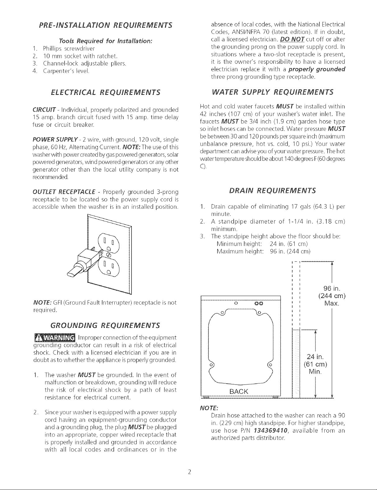
DRAIN REQUIREMENTS
1. Drain capable of eliminating 17 gab (64.3 L) per
minute.
2. A standpipe diameter of 1-1/4 in. (3.18 cm)
minimum.
3. The standpipe height above the floor should be:
Minimum height: 24in.(61 cm)
Maximum height: 96 in. (244cm)
NOTE: GFI(Ground Fault Interrupter) receptacle is not
required.
GROUNDING REQUIREMENTS
Improper connection of the equipment
grounding conductor (:an result in a risk of electrical
shock. Check with a licensed electrician if you are in
doubt asto whether the appliance isproperly grounded.
<
Tile washer MUST be grounded. In the event of
malfunction or breakdown, grounding will reduce
the risk of electrical shock by a path of least
resistance for electrical current.
<
Sinceyour washer isequipped with a power supply
cord having an equipment-grounding conductor
and a grounding plug, the plug MUSTbe plugged
into an appropriate, copper wired receptacle that
is properly installed and grounded in accordance
with all local codes and ordinances or in tile
o O0
24 in.
(61 cm)
Min,
BACK
NOTE:
Drain hose attached to the washer can reach a go
in. (229 cm) high standpipe. For higher standpipe,
use hose P/N 134369410, available flora an
authorized parts distributor.
T
96 in.
(244 cm)
Max.

ROUGH-fN DfMENSfONS
27.75
( 7o.5 ) ......................-:
24"
(6_)
6 O"
(152.4)
Power Cord
33.40
(84 8)
Draln
32.25"
(8i 9)
2,75'
(7)
SIDE
(68,6)
6.75"
(17,1)
Water Inlets
33,5'
(85 1)
BACK

LOCATION OF YOUR WASHER
DO NOT INSTALL YOUR WASHER:
1. In an area exposed to dripping water or outside
weather conditions. Tile ambient temperature
should never be below 60 ° F(I 5.6 ° C) for proper
washer(detergent breakdown) operation.
2. In an area where it will come in contact with
curtains or drapes.
3. In an area (garage or garage4ype building) where
gasoline of other flammables are kept or stored
(including automobiles).
4. On carpet. Floor MUST be solid with a maximum
slope of I/2 in. per foot (!.27 cm per 30.5 cm). To
ensure vibration or movement does not occur,
reinforcement of the floor may be necessary.
IMPORTANT
MINIMUM INSTALLATION CLEARANCES
When installed in alcove or dose8
Sides, Rear = 0 in. (0 cm)
Top = 0 in. (0 cm)
When installed in closet: Front = I in. (2.54 cm)
6. Remove the following from the back panel of the
washer: 4 packaging bolts,
2 packaging springs,
2 washers,
2 metal "P" clamps,
4 screws,
1 packaging brace.
7. Remove the 4 transport plugs from the literature
pack and install them in the corresponding holes
in the back panel of the washer.
8. Remove the 4 small hole plugs from the literature
pack and install them in the side panel holes
vacated by the packaging brace.
9. Using the shipping posts, prop up the front of the
washer approximatley 2 inches to gain access to
the service panel screws.
10. Removethe 2 screws and remove the service panel.
Closet door ventilation required; 2 Iouvered openings
each60 in2(387 cm2),3 in. (7.6 cm) from top and bottom
of door.
UNPACKING
1. Cut the shipping carton along the dotted line along
the base of the unit.
2. While in the carton carefully lay tile washer on its
back side.
3. Remove the styrofoam base.
4. Carefully return the washer to an upright position
and remove the carton.
5. Carefully move the
washer to within
4 feet (122cm) of
tile final location.
POWERCORD
\
REMOVE TWO
UPPER BOLTS_
'P' CLAMPS_
AND SPRZNGS
REMOVE LOWER
BOLTS AND
WASHERS (2),
SCREWS (4)_
AND BRACE
\
LEFT
AND RIGHT
TWO SCREWS
UNDER PANEL
FOAM BLOCKS
11. Remove the the two (2) styrofoam blocks located
under the drum (ayellow ribbon surrounds the items
to beremoved). Lift up on the drum, tilt the baseof
the foam blocks inwards toward tile rear of the
washer until free, then pull them out.
12. Removeand discardthe yellow ribbon from the front
of the washer.
13. Replace the service panel and screws.
NOTE: Ifthe washer is to be transported at a later
date, the shipping support hardware must
be reinstalled to prevent shipping damage.
Drain Hose tnstMtation
The drain hose isfield installed to allow hose orientation
to the left or right, up or down depending on location of
the house drain. Tile hose isshipped in the washer tub
with tile spring clamp on the coupler elbow and drain
hose hanger installed on the end of the hose.
.
Remove the drain hose from the tub of the washer.
2.
Pushthe hose onto the drain coupler at the upper
left of the washer back panel until the hose con-
toots the STOP RIB.

STOP RZB °
PUSH ROSE ONTO
COUPLER TO STOP RIB
DRAZR HOSE TABS
•'\,\\
SPRZNG
CLAMP
\ PROVIDED
; ON HOSE
f
INSTALLATION
.
Runsome water from the hot
and cold faucets to flush the
water lines and remove
particles that might clog up
the water valve screens.
.
Remove the inlet hoses and
rubber washers from tile
plastic bag located in the
drum of the washer and
install the rubber washers in
each end of the inlet hoses.
.
Carefully connect the inlet hose (90° elbow end)
marked "HOT" to the outside "H" outlet of the water
valve.Tighten byhand, then tighten another 2/3 turn
with pliers. Carefully connect the other inlet hose
S
(90° elbow end) to the inside "C" outlet of the water
valve. Tighten byhand, then tighten another 2/3 turn
with pliers. Do not crossthread or over-tighten
these connections.
.
Using pliers, squeeze the ears of the spring clamp
and position tile clamp sothe clamp ears_ with
and contact the tabs on the drain hose. This as-
sures proper location of the clamp to prevent leaks.
ALZGN SPRING
CLAMP EARS WITH
TABS ON ROSE
7-ORIENT HOSE TO
/ RIGHT_ LEFT, UP
TABS
/
OR DOWNAS NEEDED
BEFORE PLACING
CLAMP IN POSITION
J
/
\
r
J
j.J
\ ALWAYS ALIGN CLAMP EARS
WZTH TABS ON HOSE
4. Connect the inlet hose ends to the HOT and COLD
water faucets tightly by hand, then tighten another
2/3 turn with pliers. Turn the water on and check
for leaks.
NOTE; Use only new hoses.
5. Carefully move the washer to its final location.
NOTE: Do not use the dispenser drawer or door
to lift washer.
6. With the washer in its final position, place a level
on top of tile washer. No rocking of the washer
should exist. Adjust the front leveling legs up or
down to ensure the washer is resting solid. Rear
leg adjustment is accessible through the front
service panel.
NOTE; Keep the leg extension at a minimum to
prevent excessivevibration. The farther out
the legs are extended the more the washer
will vibrate.
7. Place the hook end of the drain hose in the drain
opening. Secure the drain hose with the cable tie
(provided in the enclosure package) to the
standpipe, inlet hose, laundry tub, etc. so the hose
does not pull out from the force of the water.

8. Plug tile power cord into a grounded outlet.
NOTE: Check to ensure the power is off at a
circuit breaker/fuse box before plugging
the power cord into an outlet.
g. Turn on the power at a circuit breaker/fuse box.
10. Readthe Operating Instructions and Owner's Guide
provided with the washer. They contain valuable and
helpful information that will save you time and
money.
11. Run the washer through a complete cycle. Check
for water leaks and proper operation.
12. If your washer does not operate, please review the
"Avoid Service Checklist" in your Owner's Guide
before calling for service.
13. Place these instructions in a location near the
washer for future reference.
NOTE: A wiring diagram and technical data sheet are
located in an envelope attached to the left hand
side panel on the inside of the washer.
"q \
\\ \
\
Cable Tie
Cable Tie
REPLA CEMENT PARTS
If replacements parts are needed for your washer,
contact the source where you purchased your washer,
call I_800_944_9044, or visit our website,
www.frigidaire.com, for the Frigidaire Company
Authorized Parts Distributor nearest you.
[_W_y±_'_,ll_LqDestroythe carton and plastic bagsafter
the washer is unpacked. Children might use them for
play. Cartons covered with rugs, bedspreads, or plastic
sheets can become airtight chambers causing
suffocation. Place all materials in a garbage container
or make materials inaccessible to children.
The instructions in this manual and all
other literature included with this washer arenot meant
to (:over every possible condition and situation that may
occur. Good safe practice and caution MUSTbe applied
when installing, operating and maintaining any
appliance.
Maximum benefits and enjoyment are achievedwhen
all the Safety and Operating instructions are
understood and practiced as a routine with your
laundering tasks.
Cable Tie
 Loading...