

Frigidaire AEQ6000ES0, AEQ6000ES1, AEQ6000ES2, AEQB6000ES0, AGQ6000ES0 Installation Guide
...Page 1
PreqnstaIBSon Requirements ................................................................. 2
_ [] Electrical Requirements ........................................................................... 2
[] Rough-In Dimensions ............................................................................... 4
[] General Installatior_................................................................................. 8
[] 7 Instalaci0n en casas m6viles ............................................................. 12
S{]_C (St _9_}5_*<*' ' • _¢ _¢_ _,.sx__,_ft_#_ Requerimientos para la puesta a tierra .......................................... I4
,/ ,,_ _'C £'1 _(_¢JS_@ y Conexi6nes el#ctricas - trifilares ................................................ 14
Before beginning installation, carefully read these instructions. This will simplify the installation and ensure the dryer is installed correctly
and safely, Leave these instructions near the Dryer after installation for future reference.
NOTE: The electrical service to the Dryer must conform with local codes and ordinances and the latest edition of the National Electrical Code, ANSI/NFPA
70, or in Canada, the Canadian electrical code C22.1 part 1,
NOTE: The gas service to the Dryer must conform with local codes and ordinances and the latest edition of the National Fuel Gas Code ANSI Z22icL1, or
in Canada, CAN/ACG B149,1-2000
NOTE: The Dryer is designed under ANSI Z 21.5.1 or ANSI/UL 2158 - CAN/CSA C22.2 No. 112 (latest editions) for HOME USE only. This Dryer is not
recommended for commercial applications such as restaurants or beauty salons, etc.
Exhaust System Requirements .................................................... 2-/3
GasSupply Requirements ........................................................................ /:_
Location of Your Dryer............................................................................. 3
Mobile Home Installation ......................................................................... 5
Unpacking .......................................................................................... 5
Reversing Door Swing ............................................................................. 6
Electrical Installation ........................................................................ 7
Grounding Requirements ................................................................ 7
Electrical Connections--S-wire ............................................................... 7
Electrical Connections--4-wire .............................................................. 8
GasConnection ...................................................................................... 8
Replacement Warts................................................................................. 8
EspanOI .................................................................. 9-I 5
Requerimientos de instalaci0n preliminares ............................................. 9
Requerimientos eld,ctricos....................................................................... 9
Requerimientos del sistema de escape ............................................. 9-10
Requerimientos del suministro degas..................................................... 10
Ubicaci6n desusecadora....................................................................... I0
Dimensiones para la instalaci0n .......................................................... 11
Desembalaje .............................................................................. 12
Puerta reversible ........................................................................ 13
Instalacion eF,ctrica ....................................................................... 14
Conexi6nes eld_ctricas - tetrafilares ............................................... 15
Conexion del gas ........................................................................... 15
General InstaBd6n ............................................................................ 15
Piezas de recambio ....................................................................... 15
Antes de comenzar la instaJadbn, lea cuidadosamente estas instrucciones. Esto simpBficar_ la instaJad6n y asegurar_ qua la secadora se
instaJe correctamente y de t_anera segura. Despu_s de completar la instaladdn, coloque estas instrucciones cerca de la secadora para
referenda futura,
NOTA: La alimentaci6n el#,ctrica para B secadora debera cumplir con los codigos y regBmentos locales y con la Okima edicion del C6digo El_,ctrico National,
ANWNFPA 70
NOTA: La alimentad6n de gas para la secadora debera cumplir con los c6digos y reglamentos IocaP,s y con B 01tima edici0n del C6digo National para Gases
Combustibles, ANSI Z22€,1
NOTA: Lasecadora estaclasificada para USO DOMESTICOsolamente, de acuardo con la norma ANSI Z 215, I o ANSI/UL 2158 - CAN/CSA C22.2 (las 01timas
edici6nes), Esta secadora no se recomienda para uso commercial tal como en r,:,staurantes, salones de belleza, etc,
personal injury or loss of life.
- Do not store or use gasoline or other flammable vapors and liquid in the vicinity of this or any other appliance,
- WHAT TO DO IF YOU SMELL GAS
. Do not try to light any appliance,
Do not touch any electrical switch; do not use any phone in your building,
Clear the room, building or area ol all occupants.
Immediately call your gas supplier from a neighbor's phone. Follow the gas supplier's instructions.
If you cannot reach your gas supplier, call the fire department.
Installation and service must be performed by a qualified installer, service agency or the gas supplier.
_.__ Para su seguridad, siga las instruccior_es contenidas en este manual a fin de reducir a un minimo los riesgos de incendio o explosi6n o
para evitar da¢/os materiales, lesiones personales o la muerte.
No almacene ni utilice gasolina u otros vapores y Iiquidos infiamabbs en la proximidad de #_steo de cualquier otto artefacto el_',ctrico,
QUE DEBE HACER SI PERCIBE OLOR A GAS
. No trate de encender ningOn artefacto eledrico
. No toque ning0n interruptor el6ctrico; no use ning0n teblono en su edificio,
. Haga salir a todos los ocupantes de la habitaci6n, del edificio y del lugar.
. Llama a su proveedor de gas desde el tebfono de un vecino. Siga lab instrucciones del proveedor de gas.
• Sino Iogra comunicarse con su proveedor de gas, Ilame al departamento de bomberos,
La instalacior_ y el servicio de mantenimiento debe de realizarlos un instalador calificado, la agencia de servicios o el proveedor de gas.
For your safety the information in this manual must be followed to minimize the risk of fire or explosion or to prevent property damage,
Printed in U.S.A. P/N 134721800 (0601)
Page 2
PRE-INSTALLATION REQUIREMENTS
EXHA UST 5 Y$TEM REQUIREMENTS
Tools and MateHMs Required for ktstMladon:
1. PhiBps head screwdriver
2. Channe[qock adjustable pliers.
3, Carpenter's [evek
4, Flat or straight blade screwdriver,
5. Duct tape,
6, Rigid or flexible meta[ 4 inch (10.2 cm) duct,
7. Vent hood.
8, Pipe thread sealer (Gas).
9, Plastic knife.
ELECTRICAL REQUIREMENTS
ELECTR/C Dryer
CIRCUIT - individual 30 amp. branch circuit fused with 30 amp, minimum
time delay fuses or circuit breaker.
POWER SUPPLY - 3 wire or 4-wire, 240 volt, single phase, 60 Hz,
Alternating Current
POWER SUPPLY CORD KiT - The dryer MUST employ a 3<onductor
power supply cord NEMA 10-30 type SRDT rated at 240 volt AC
minimum, 30 amp., with S open end spade lug connedors with upturned
ends or closed loop connectors OR a 4<onductor power supply cord
NEMA 14-30 type SRDT or ST (as required) rated at 240 volt AC
minimum, 30 amp., with 4 open end spade lug connectors with upturned
ends or closed loop connectors and marked for use with clothes dryers.
If being installed in a new branch circuit installation, manufactured
(mobile) home, recreational vehicle or area which prohibits grounding
through the neutral conductor, the dryer MUST employ a 4<onductor
power supply cord NEMA 14-€0 type SRDT or ST {as required) rated at
240 volt AC minimum, 30 amp,, with 4 open end spade lug connectors
with upturned ends or closed loop connectors and marked for use with
clothes dryers, See ELECTRICAL CONNECTIONS for additional
instructions.
CANADA - A 4 wire power cord is installed on dryer,
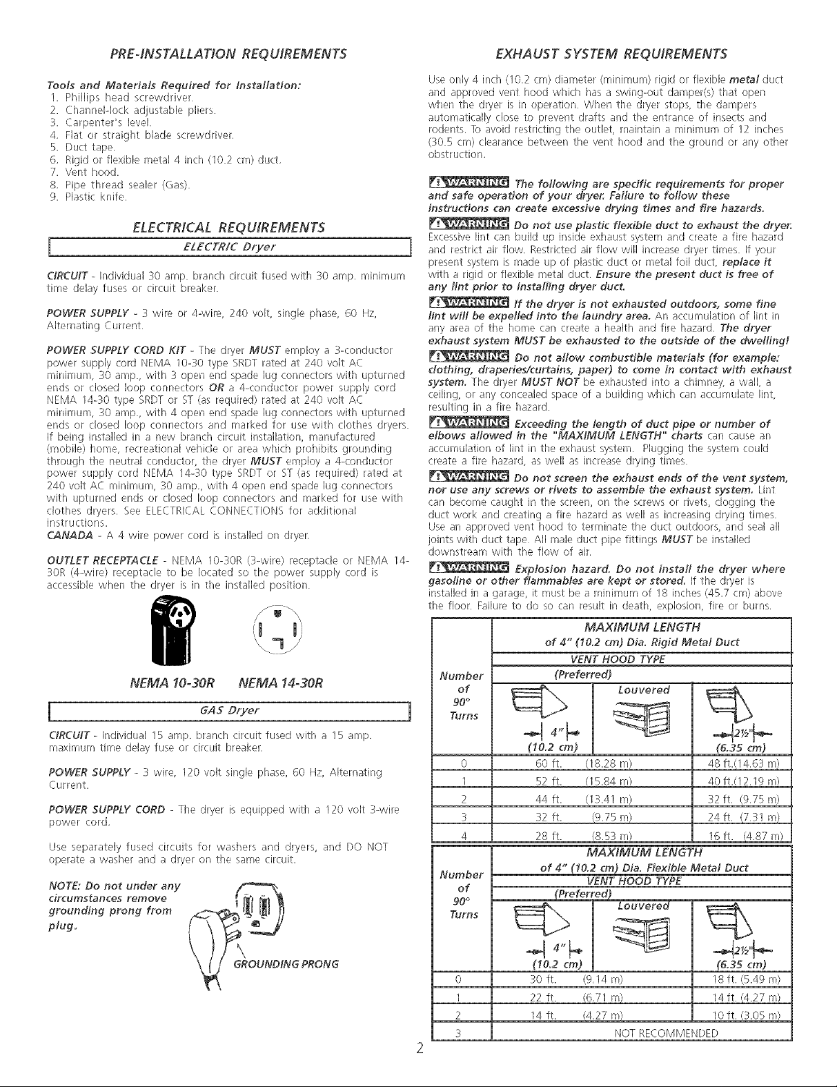
OUTLET RECEPTACLE - NEMA 10-30R (3-wire) receptacle or NEMA 14-
30R (4-wire) receptacle to be located so the power supply cord is
accessible when the dryer is in the installed position
NEMA 10-30R NEMA 14-30R
I GAS Dryer
CIRCUIT - Individual 15 amp. branch circuit fused with a 15 amp.
maximum time delay fuse or circuit breaker.
POWER SUPPLY - 3 wire, 120 volt single phase, 60 Hz, Alternating
Current.
POWER SUPPLY CORD - The dryer is equipped with a 120 volt 3-wire
power cord,
Use separately fused circuits for washers and dryers, and DO NOT
operate a washer and a dryer on the same circuit.
NOTE: Do not under any
circumstances remove
grounding prong from
plug.
Use only 4 inch (10,2 cm) diameter (minimum) rigid or flexible metal duct
and approved vent hood which has a swing-out damper(s) that open
when the dryer is in operation. When the dryer stops, the dampers
automatically close to prevent drafts and the entrance of insects and
rodents. To avoid restricting the outlet, maintain a minimum of 12 inches
(30.5 crn) clearance between the vent hood and the ground or any other
obstruction,
and safe operation of your dryer. Failure to follow these
instructions can create excessive drying times and fire hazards.
Excessive lint can build up inside exhaust system and create a fire hazard
and restrict air flow. Restricted air flow will increase dryer times. If your
present system is made up of plastic duct or metal foil duct, replace it
with a rigid or flexible metal duct. Ensure the present duct is free of
any riot prior to installing dryer duct.
lint wilt be expelled into the laundry area. An accumulation of lint in
any area of the home can create a heakh and fire hazard. The dryer
exhaust system MUST be exhausted to the outside of the dweRing!
dothing, draperies/curtains, paper) to come in contact with exhaust
system. The dryer MUST NOT b_ exhausted into a chimney, a wall, a
ceiling, or any concealed space of a building which can accumulate lint,
resulting in a fire hazard.
elbows allowed in the "MAXIMUM LENGTH" charts car/ cause an
accumuBdon of lint in the exhaust system. Plugging the system could
create a fire hazard, as well as increase drying times.
nor use any screws or Hvets to assemble the exhaust system. Lint
can become caught in the screen, on the screws or rivets, clogging the
duct work and creating a fire hazard as well as increasing drying times.
Use an approved vent hood to terminate the duct outdoors, and seal all
joints with duct tape All male duct pipe fittings MUST be installed
downstream with the flow of air,
gasofine or other flammables are kept or stored. If the dryer is
installed in a garage, it must be a minimum of 18 inches (45.7 cm) above
the floor. Failure to do so can result in death, explosion, fire or burns,
Number
of
90°
Turns
0
1
2
3
4
Number
of
90°
Turns
The following are specific requirements for proper
Do not use plastic flexible duct to exhaust the dryer
If the dryer is not exhausted outdoors, some fine
Do not allow combustible materials (for example:
Exceeding the length of duct pipe or number of
Do not screen the exhaust ends of the vent system,
Explosion hazard. Do not install the dryer where
MAX/MUM LENGTH
of 4" (10.2 cm) Dia. Rigid Metal Duct
VENT HOOD TYPE
(Preferred)
Louvered
(10.2 cm)
6O ft.
52 ft.
44 ft.
32 ft.
28 ft.
of 4" {10.2 cm) Dia, Flexible Metal Duct
(18.28 m)
(15.84 m)
(13.41 m)
(9.75 m)
(8.53 m)
MAXIMUM LENGTH
VENT HOOD TYPE
{Preferred)
Louvered
(6.35 cm)
48 ft.(14.63 m)
40 ft.(12.19 m)
32 ft. (9.75 m)
24ft, (7:11 m)
16 ft. (487m)
(I0.2 cm)
0
I
2
3
30 ft. (9,I4 m)
22 ft. (6,71 m)
14 ft. (4,27 m)
NOT RECOMMENDED
(6.35 cm)
18 ft. (5.49 m)
14ft. (4.27 m)
10 ft, (3.05 m)
Page 3
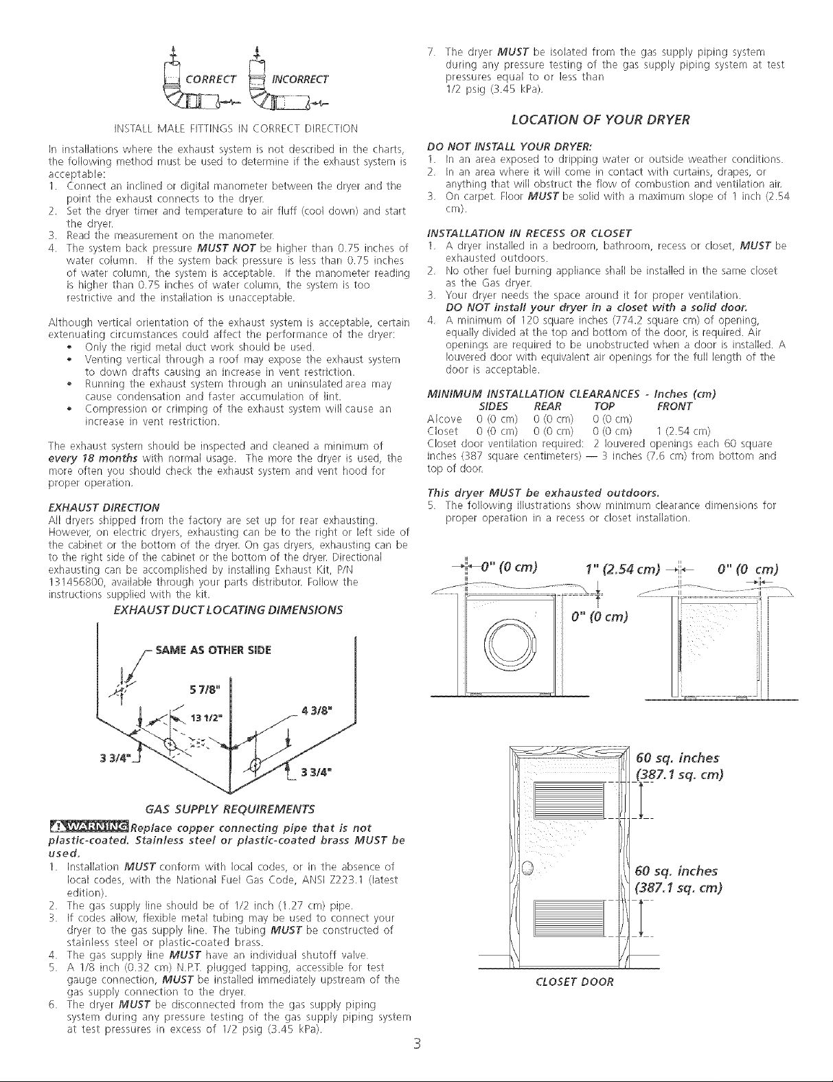
_JNCORRECT
7 The dryer MUST be isolated from the gas supply piping system
during any pressure testing of the gas supply piping system at test
pressures equal to or less than
I/2 psig (345 kPa),
INSTALLMALEFITTINGSINCORRECTDIRECTION
Ininstallationswheretheexhaustsystemisnotdescribedintilecharts,
thefollowingmethodmustbeusedtodetermineiftheexhaustsystemis
acceptable:
I. Connectaninclinedordigitalmanometerbetweenthedryerandthe
pointtheexhaustconnectstothedryer,
2. Setthedryertimerandtemperaturetoairfluff(cooldown)andstart
thedryer
3. Readthemeasurementonthemanometer
4. ThesystembackpressureMUST NOT be higher than 0.75 inches of
water column. If the system back pressure is less than 0.75 inches
of water column, the system is acceptable. If the manometer reading
is higher than 0,75 inches of water column, the system is too
restrictive and the installation is unacceptable,
Although vertical orientation of the exhaust system is acceptable, certain
extenuating circumstances could affect the performance of the dryer:
,, Only the rigid metal duct work should be used.
,, Venting vertical through a roof may expose the exhaust system
to down drafts causing an increase in vent restriction.
,, Running the exhaust system through an u/finsulated area may
cause condensation and faster accumulation of lint.
,, Compression or crimping of the exhaust system will cause an
increase in vent restriction.
The exhaust system should be inspected and cleaned a minimum of
every I8 months with normal usage. The more the dryer is used, the
more often you should check the exhaust system and vent hood for
proper operation,
EXHAUST DIRECTION
All dryers shipped from the factory are set up for rear exhausting.
Howevel, on electric dryers, exhausting can be to the right or left side of
the cabinet or the bottom of the dryer. On gas dryers, exhausting can be
to the right side of the cabinet or the bottom of the dryer. Directional
exhausting can be accomplished by installing Exhaust Kit, P/N
131456800, available through your parts distributor. Follow the
instructions supplied with the kit.
EXHAUST DUCT LOCATtNG DiMENSiONS
LOCATION OF YOUR DRYER
DO NOT iNSTALL YOUR DRYER:
1. In an area exposed to dripping water or outside weather conditions.
2, In an area where it will come in contact with curtains, drapes, or
anything that will obstruct the flow of combustion and ventilation air,
3, On carpet, Floor MUST be solid with a maximum slope of 1 inch (2.54
cm).
iNSTALLATiON iN RECESS OR CLOSET
1, A dryer insta]k_d in a bedroom, bathroom, recess or closet, MUST be
exhausted outdoors.
2, No other fuel burning appliance shall be installed in the same closet
as the Gas dryer.
:L Your dryer needs the space around it for proper ventilation.
DO NOT instafl your dryer in a closet with a sofid door.
4, A minimum of 120 square inches (774.2 square cm) of opening,
equally divided at the top and bottom of the door, is required. Air
openings are required to be unobstructed when a door is installed. A
Iouvered door with equivalent air openings for the full length of the
door is acceptable.
MiNiMUM iNSTALLATION CLEARANCES o Inches (cm)
SIDES REAR TOP FRONT
Alcov:_ 0(0:m) 0(0:m) 0(0cm)
Closet 0 (0 cm) 0 (0 cry]) 0 (0 cm) I (2.54 cry])
Closet door ventilation required: 2 Iouvered openings each 60 square,
inches (38-7 square centimeters) -- 3 inches (7,6 cm) from bottom and
top of door,
This dryer MUST be exhausted outdoors,
5 The following illustrations show minimum clearance dimensions for
proper operation in a recess or closet installation,
_i_O" (ecm) I" (2.54 cm) _;;_ O"(ecm)
_11 _
5 7/8"
jj/_ SAME AS OTHER SiDI:
_Reptace copper connecting pipe that is not
plasticocoated, Stainless steet or piasticocoated brass MUST be
used,
1. Installation MUST corfform with local codes, or in the absence of
local codes, with the National Fuel Gas Code, ANSI Z223,I (latest
edition).
2. The gas supply line should be of 1/2 inch (1.27 cm) pipe.
3. if codes allow, flexible metal tubing may be used to connect your
dryer to the gas supply line. The tubing MUST be constructed of
stainless steel or plastic-coated brass.
4. The gas supply line MUST }lave an individual shutoff valve
5. A I/8 inch (0.32 cm) N,RT, plugged tapping, accessible for test
gauge connection, MUST be installed immediately upstream of the
gas supply connection to the dryer.
6. The dryer MUST be disconnected from the gas supply piping
system during any pressure testing of the gas supply piping system
at test pressures in excess of I/2 psig (;3.45 kPa).
/ 4 318_
13I/2" f
GAS SUPPLY REQUIREMENTS
CLOSET DOOR
3
Page 4
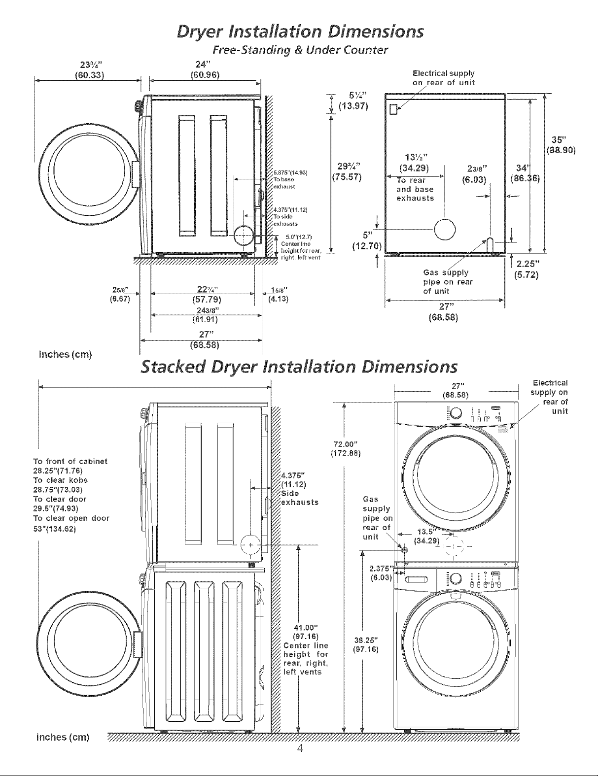
23%"
(60°33)
Dryer tnstM/ation Dimensions
Free-Standing & Under Counter
24"
(60.96) Electrical euppty
__(13.97) [_
5.875"(¢4.93)
To base
exhaust
4.375"{11._2)
To side
exhausts
5.g"(12.7) 5 !I
CenterJibe (12.70)
r height for rear, __
29%"
175,57)
on rear of unit
13%"
(34,29) 23/8"
35 _
'_8&90)
34 _
(86.:6)
4---
2
To front of cabinet
88.25"{71.78)
To c_ear kobs
28.75"(73.03)
To clear door
29.8"(74.93)
To clear open door
53"(134.82)
85/8"
(8.67)
pipe on rear
, right, left refit _'4 Gas s_y
_!t 5/8" of unit
(4.t3) 27"
(s&sa)
Stacked Dryer tnstM/adon Dimensions
72.00"
(172.88)
Gas
supply
pipe on
rear of
unit "--.,
2.375",
(8.03)
(34.29) _" ,,
27 _
(88.58)
/
\
I"
(&72)
I 2,25"
E_ectrica_
supply on
rear of
unit
inches (cm)
38.25"
(87.fS)
4
Page 5
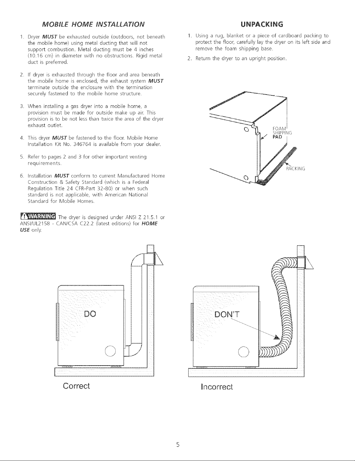
MOBILE HOME INSTALLATION
UNPACKMNG
1 Dryer MU5T be exhausted outside (outdoors, not beneath
the mobile home) using metal ducting that will not
support combustion Metal ducting must be 4 inches
(10.16 cm) in diameter with no obstructions Rigid metal
duct is preferred
2 If dryer is exhausted through the floor and area beneath
the mobile home is enclosed, the exhaust system MUST
terminate outside the enclosure with the termination
securely fastened to the mobile home structure.
3 When installing a gas dryer into a mobile home, a
provision must be made for outside make up air This
provision is to be not less than twice the area of the dryer
exhaust outlet
4 This dryer MUST be fastened to the floor. Mobile Home
Installation Kit No 346764 is available from your dealer.
5 Refer to pages 2 and 3 for other important venting
requirements
6 Installation MUST conform to current Manufactured Home
Construction & Safety Standard (which is a Federal
Regulation Title 24 CFR-Part 32-80) or when such
standard is not applicable, with American National
Standard for Mobile Homes
1. Using a rug, blanket or a piece of cardboard packing to
protect the floor, carefully lay the dryer on its left side and
remove the foam shipping base
2. Return the dryer to an upright position
FOAM
SHIPPING
The dryer is designed under ANSI Z 21.5.1 or
ANSI/UL2158 - CAN/CSA C222 (latest editions) for HOME
USE only.
DO
Correct
incorrect
Page 6

DRYER DOOR REVERSAL mNSTRUCTIONS
Be sure to wear gloves while reversing the door assembly.
5. Remove the hinge cutout plug, Rotate it and install it in the
1. Open the dryer door, opposite side of the outer door.
2. Remove the five screws, 1 thru 5 and the two screws, 6 and
7, that attach the inner door assembly to the outer door
assembly. Lift the outer door assembly out of the inner
door assembly and place on a soft flat surface,
6, Remove the two screws that secure the hinge to the front
panel.
Remove the two (2) hinge attachment screws and place the
inner door assembly on a soft flat surface.
4. Remove the screws that attach the strike plate. Rotate the
strike plate and reattach it to the opposite side of the inner
door.
Remove the catch plate from the front panel,
8. Rotate and reinstall the hinge and the catch plate in the sides
opposite of where they were removed.
9, Reattach the door assemblies in reverse order.
10, Close the door,
Page 7

ELECTRICAL INSTALLATION
j ELECTRICDryer j [
F:_ The following are spedfic requirements for proper and
safe electrical installation of your dryer, Failure to follow these
instructions can create electrical shock andlor a fire hazard.
This appfiance MUST be properly grounded. Uectrkal
shock can result if tile dry_,r is not properly grounded Follow the
instructions in this manual for proper grounding.
Do not use an extension cord with this dryer. Some
extension cords are not designed to withstand the arnounts of electrical
current this dryer utilizes and can melt, creating electrical shock and/or
fire hazard. Locate the dryer within reach of the receptacle for the
length power cord to be purchased, allowing some slack in the cord,
Refer to the pre-installation requirements in this manual for the proper
power cord to be purchased.
A U.L approved strain refief must be installed onto
power cord. If the strain relief is not attached, the cord can be pulled out
of the dryer and can be cut by any movement of the cord, resulting in
electrical shock,
Do not use an aluminum wired receptacle with a
copper wired power cord and plug (or vice versa). A chemical
re-,action occurs between copper and ahmhqum and can cause electrical
shorts. The proper wiring and receptacle is a copper wired power
cord with a copper wired receptacle.
NOTE: Dryers operating on 208 volt pow_,r supply will have longer
drying times than operating on 240 volt power supply
GROUNDING REQUIREMENTS
Improper connection of the equipment grounding conductor
can result in a risk of electrical shock. Check with a licensed electrician if
you are in doubt as to whether the appliance is properly grounded,
For a grounded, cord-connected dryer:
1, The dryer MUST be grounded, in the event of a malfunction or
breakdown, grounding will reduce the risk of electrical shock by a
path of least resistance for electrical current,
ALL GAS Dryers
This dryer isequipped with athree-prong (grounding) plug for your protection
against shock hazard and should be plugged directly into a properly grounded
three-prong receptacle. Do not cut or remove the grounding prong from this
plug,
ELECTR/CAL CONNECTtONSFOR 3-W/RE SYSTEM
NONoCANAD/AN ELECTR/C Dryer J
Remove th_ screws securing the terminal block access cover and the,
strain relief mounting bracket located on the back of the dryer upper
corner
2,
Install a U,L. approved strain relief into the power cord entry hole of
the mounting bracket. Finger tighten the nut only at this time
3,
Thread a U,L. approved 30 amp. power cord, NEMA 10-30 type
SRDT, through the strain relief.
4,
Attach the power cord neutral (center wire) conductor to the silver
colored center terminal on the terminal block, Tighten the screw
securely.
Attach the remaining two power cord outer conductors to the outer
brass colored terminals on the terminal block. Tighten both screws
securely.
at connections
Reattach the strain relief mounting bracket to the back of the dryer
with two screws Tighten screws securely.
GREEN
Do not make a sharp bend or crimp wiring/conductor
1
2, If your dryer is equipped with a power supply cord having an
equipment-grounding conductor and a grounding plug, the plug
MUST be plugged into an appropriate, copper wired receptacle that
is properly installed and grounded in accordance with all local codes
and ordinances. If in doubt, call a licensed electrician. Do not
modify plug provided with the appliance.
For a permanently connected dryer:
1, The dryer MUST be connected to a grounded metal, permanent
wiring system; or an equipment grounding conductor must be run
with the circuit conductors and connected to the equipment-
grounding terminal or lead on the appliance.
Canad/an ELECTR/C Dryer
Improper connection of the equipment grounding
conductor can result in a risk of electrical shock. Check with a licensed
electrician if you are in doubt as to whether the appliance is properly
grounded.
For a qrounded, cord-connected drw, r:
1, The dryer must be grounded, In the event of a malfunction or
breakdown, grounding will reduce the risk of electrical shock by a
path el least resistance for electrical current,
2, Since your dryer is equipped with a power supply cord having an
equipment-grounding conductor and a grounding plug, the plug must
be plugged into an appropriate outlet that is properly installed and
grounded in accordance with all local codes and ordinances, if in
doubt, call a licensed electrician Do not modify plug provided
with the appliance,
BRACKET POWER CORD
7.
Tighten the screws securing the cord restraint firmly against the
power cord.
8.
Tighten the strain relief nut securely so the strain relief does not
turn.
9.
Reinstall the terminal block cover.
Page 8
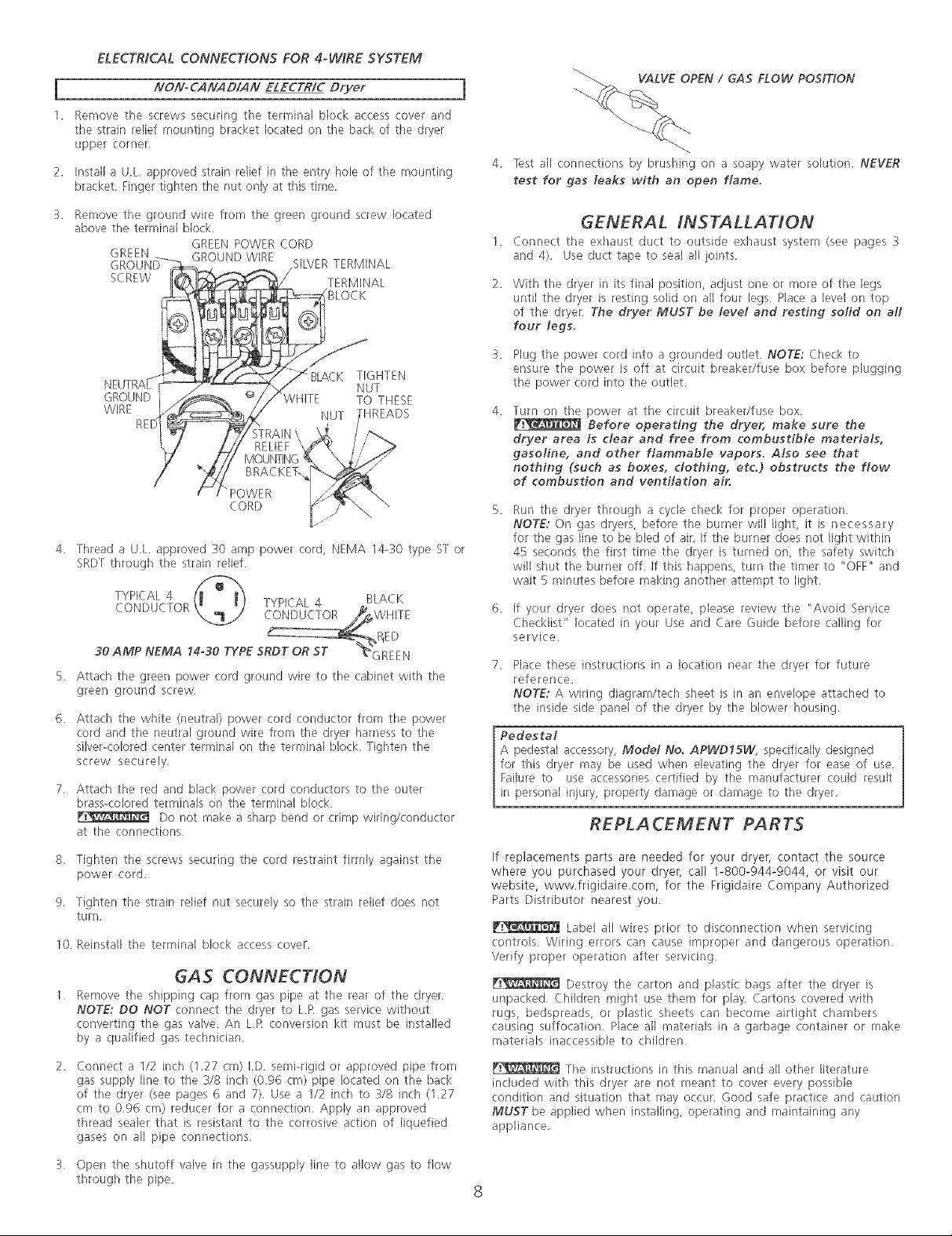
ELECTRICAL CONNECTIONS FOR 4-W/RE SYSTEM
I NONoCANAD/AN ELECTR/C Dryer
1. Rernov_ th_ screws securing th_ terminal block access cover and
the strain relief mounting bracket located on the back of the dryer
upper corner,
2. Install a U.L, approved strain relief in the entry hole of the mounting
bracket, Finger tighten the nut only at this time.
_-_ VALVE OPEN / GAS FLOW POSITION
4. lest all connections by brushing on a soapy water solution. NEVER
test for gas leaks with an open flame.
3. Remove the ground wire from the green ground screw located
above the terminal block.
GREEN GROUND WIRE
SCREW TERMINAL
GROUND WHITE TO THESE
WIRE HREADS
4. Thread a U.L. approved 30 amp power cord, NEMA 14-30 type ST or
SRDTthrough the strain relief.
TYPICAL 4 BLACK
CONDUCTOR TYPICAL 4
30 AMP NEMA 14o30 TYPE SRDT OR BT "_GREEN
Attach tile green power cord ground wire to the cabinet with the
green ground screw,
Attach the white (neutral) power cord conductor from the power
cord and the neutral ground wire from the dryer harness to the
silver-colored center terminal on the terminal block. Tighten the
screw securely.
Attach the red and black power cord conductors to the outer
brass<olored terminals on the terminal block,
at the connections,
8. Tighten the screws securing the cord restraint firmly against the
power cord.
9, Tighten the strain relief nut securely so the strain relief does not
turn,
10, Reinstall the terminal block access cover.
GREEN POWER CORD
SILVERTERMINAL
BLOCK
BLACK TIGHTEN
NUT
STRAIN\
RELIEF "
BRACKET.
>OWER
CORD
CONDUCTOR WHITE
_ ,_P_ED
Do not make a sharp bend or crimp wiring/conductor
GAS CONNECTION
Remove the shipping cap from gas pipe at the r_,arof th_ dryer.
NOTE: DO NOT connect the dryer to L.R gas service without
converting the gas valve. An L,R conversion kit must be installed
by a qualified gas technician,
GENERAL INSTALLATION
1. Cennect the exhaust duct to outside exhaust syst_,m (see pages 3
and 4). Use duct tape to seal all joints,
With the dryer in its final position, adjust one or more of the legs
until the dryer is resting solid on all four legs Place a level on top
of the dryer, The dryer MUST be level and resting sofid on aft
four legs.
3. Plug the power cord into a grounded outlet. NOTE: Check to
ensure the power is off at circuit breaker/fuse box before plugging
the power cord into the outlet.
Turn on the power at the circuit breaker/Iuse box.
Before operating the dryer, make sure the
dryer area is clear and free from combustible materials,
gasoline, and other flammable vapors. Also see that
nothing (such as boxes, clothing, etc.) obstructs the flow
of combustion and ventilation air.
Run the dryer through a cycle check for proper operation.
NOTE: On gas dryers, bolero the burner will light, it is necessary
for the gas line to be bled of air. If the burner does not light within
45 seconds the first time the dryer is turned on, the safety switch
will shut the burner off. if this happens, turn the timer to "OFF" and
wait Bminutes before making another attempt to light,
6. If your dryer does not operate, please review the "Avoid Service
Checklist" located in your Use and Care Guide before calling for
service,
Place these instructions in a location near the dryer for future
reference.
NOTE; A wiring diagram/tech sheet is in an envelope attached to
the inside side panel of the dryer by the blower housing,
Pedestal
A pedestal accessory, Model No. APWD15W, specifically designed
for this dryer may be used when elevating the dryer for ease of use,
Failure to use accessories certified by the manufacturer could result
in personal injury, property damage or damage to the dryer,
REPLA CEMENT PARTS
If replacements parts are needed for your dryer, contact the source
where you purchased your dryer, call 1-800-944-9044, or visit our
website, www.frigidaire.com, for the Frigidaire Company Authorized
Parts Distributor nearest you.
Label all wires prior to disconnection when servicing
controls. Wiring errors can cause improper and dangerous operation.
Verify proper operation after servicing
Destroy the carton and plastic bags after the dryer is
unpacked, Children might use them for play, Cartons covered with
rugs, bedspreads, or plastic sheets can become airtight chambers
causing suffocation, Place all materials in a garbage container or make
materials inaccessible to children.
Connect a 1/2 inch (1,27 cm) I.D. semi-rigid or approved pipe from
gas supply line to the 3/8 inch (0.96 cm) pipe located on the back
of the dryer (see pages 6 and 7). Use a I/2 inch to :V8 inch (1,27
cm to 0.96 cm) reducer for a connection. Apply an approved
thread sealer that is resistant to the corrosive action of liquefied
gases on all pipe connections,
3. Open the shutoff valve in the gassupply line to allow gas to flow
through the pipe.
The instructions in this manual and all other literature
included with this dryer are not meant to cover every possible
condition arid situation that may occur. Good safe practice and caution
MUST be applied when installing, operating arid maintaining any
appliance,
8
Page 9

REQUERIMENTOS DE INSTALA CION PRELIMINARES
Herramientas y materiales necesarios para la #tstalad6n:
I. Destorni%dor Phillips
2. Alicates universaies
3. Nivel de carpintero
4. Destorniiiador para torniilo de cabeza plana o recta
5. Cinta para ductos
6. Ducto metalico rigido o flexible de 4"(10,2 cm)
7. Caperuza de salida
8. Sellador de tubenas (gas)
9, Un cuchillo d_,plastico
REQUERIMENTOS ELECTRICOS
Secadoras EZECTR/CAS
CfRCUITO - Circuito derivado individual de 30 amperios, con fusibles de 30
amp, del tipo de retardo mlnimo o disyuntores,
ALIMENTAC/ON ELeLCTRICA- Corriente alterna, monofasica, 60 Hz, 240
voltios; trifilar o tetrafilar.
CORDON ELECTRICO - En la secadora se DEBE usar un cordon eld,ctrico
trifilar NEMA 10-30 tipo SRD] para un voltaje nomir_al mirfimo de 240 voltios
CA, 30 amp., con 3 conectores de horquillas con terminales abiertos y
extremes dirigidos hacia arriba o conectores de anillo cerrado y marcados
para use en secadoras de ropa e un cordon electrico tetrafilar NEMA 14-130
tipo SRDTo ST(come sea necesario) para un voltaje nominal minimo de 240
voltios CA, 30 amp, con 4 conectores de horquillas (:on terminales abiertos y
extremes dirigidos hacia arriba o conectores de anillo cerrado.
Si siendo instalado en una nueva instalacion del circuito del rama, un
vehkulo casero, recreacional (m0vil) manufacturado o un area que
prohiben el poner a tierra a trav#,s del conductor neutral, se DEBE utilizar
un cordon ebctrico tetrafilar NEMA 14-30 tipo SRDT o ST (come sea
necesario) para un voltaje nominal minimo de 240 voltios CA, 30 amp. con 4
conectores de horquillas con terminales abiertos y extremes dirigidos hacia
arriba o conectores de anillo cerrado y marcados para use en secadoras de
ropa. Ver CONEXIONES ELECTRICASpara adicional informacion.
(Canad4 - un cordon de suministro de energla de 4 alambres es instalado en
la secadora.)
TOMACORRIENTE - El tomacomente NEMA 10430R (3 alambres) o NEMA
14-30R (4 alambres) debe estar ubicado de manera que el cordon el#,ctrico
Ilegue hasta el cuando la secadora este instalada,
NEMA 10-30R NEMA 14-30R
Secadofas a GAS 1
CfRCUITO - Circuito individual derivado d_, 15 amp, con fusibles d_, 15 amp,
de retardo maximo o disyuntor,
Utilice circuitos de fusibles separados para la lavadora y la secadora, No
opere una lavadora y una secadora en el mismo circuito.
ALIMENTACION ELECTRtCA - Corriente alterna, monofasica, 60 Hz, 120
voltios, trifilar.
CORDON ELECTRICO - La secadora esta equipada con un cordon
eF_ctrico trifilar para 120 voltios,
NOTA: No
saque per
_r_ LOSsiguientes requerimientos son espedficos para
el funcionar_iento correcto y seguro de su secadora. El
incumplimiento de estas instrucdones puede causar prolongad6n
excesiva del dempo de secado y riesgos de incendio.
No use ductos flexibles de pl&stico para et escape de ta secadora,
SeDue@ acumular un exceso de pelusas en el sistema de escape, crear un
riesgo y obstruir el fiujo de aire. La restriction del fiujo del aire prolongara el
tiempo de secado. Sisu sistema de escape actual tiene ductos de plastico o
de laminas metalicas delgadas, reempl4celo con un ducto metalico rlgido
o flexible. AsegOrese de que los ductos existentes no reagan pelusas
antes de instatar et ducto de la secadora.
F_ Si el escape de la secadora no se dirige at exterior, algunas pelusas
finas ser_n sopladas hacia el recinto donde se efectOa el lavado. La
acumulaciOn de pelusas en cualquier lugar de la casa, puede crear un
peligro para la sahd y un riesgo de incendio, iElsistema de escape de la
secadora DEBE estar dirigido hacia el extedor de la viviendM
F_ No permita que los materiMes combustibles (per ejemplo: la
ropa, cortinas/cordnajes, papeO tengan contacto con los ductos, El
escape de la secadora NO DEBE dirigirse hacia el interior de una
chimenea, hacia una pared, hacia el cielo raso o hacia cualquier otto
espacio reducido del edificio, deride puede ocurrir acumulaciOn de pelusas
y constituir un peligro de incendio.
Exceder la Iongitud dot conducto rigid 9 o los nOmeros de codes
permitidos en los diagramas "LARGO MAXIMO" puede disminuir la
capacidad de exhaustaciOn del sistema. Obstruir el conducto puede
provocar peligro de incendio, asi come aumentar el tiempo de secado
No coloque un filtro en el extreme dot escape del sistema ni
emptee tornillos o remaches para ensamblar el sistema de escape.
Las pelusas podrian quedar atrapadas en los filtros, en los tornillos o en los
remaches, Io cual obstruiria el sistema de escape y creana un riesgo de
incendio, asi come tambien prolongaria el tiempo de secado. Use una
caperuza de salida adecuada para el extreme del ducto que salga al
exterior de la vivienda y selle todas lasjuntas con cinta adhesiva para
ductos, ]])dos los accesorios de tubena roaches, DEBEN ser instalados
aguas abajo del fiujo de aire.
guarda gasolina u otros materiales inflamables. Si la secadora se
instah en un garage, ella debe estar per Io menos 18 pulgadas (45,7 cm) per
endma del suelo. El incumplimiento puede resultar en la muerte, explosion,
incendio, o quemaduras,
NOmero
de Codes
a 90°
Riesgo de explosi6n. No instate la secadora donde se
LARGO MAXIMO del Conducto Met&lice Rigido
de 4" (10,2 cm} de Di&metro
TIPO DE CAPERUZA DE SAUDA
(Preferido)
Apersianada
-4 4:,p.
(10,2 cm)
0
1
2
3
4
60 pies
52 pies
44 pies
32 pies
28 pies
LARGO M,&XIMO det Conducto Met&lice FJexible
TIPO DE CAPERUZA DE SAUDA
(18,28 m)
(15,84 m)
(13,41 m)
(9,75 m)
(8,53 m)
de 4" (10,2 cm) de Di_metro
(Preferido)
(&S5 era)
48 pies(14,63 m)
40 pies(12,19 m)
32 pies (9,75 m)
24 pies (7,31 m)
16 pies (4,87 m)
REQUERIMIENTOS DEL SISTEMA DE ESCAPE
Utilice solamente ductos met4licos, rigidos o fiexibles de 4"
(10,2 cm) de diametro (mirfimo) y una caperuza de salida de use aprobado,
con registros que giren hacia afuera que se abren cuando la secadora se
encuentra en funcionamiento, Cuando la secadora se detiene, los registros
se cierran automaticamente para evitar las corrientes de aire y la entrada
de insectos y roedores. Paraevitar obstruir la salida, mantenga una altura
libre minima de 12 "(30,5 cm) entre la caperuza de salida y el piso o entre
cualquier otra obstruccion.
%1 do. -4
(10,2 era) (&35 era)
0 30 pies (9,14 m) 18 pies (5,49 m)
1 22 pies (6,71 m) 14 pies (4,27 m)
2 14 pies (4,27 m) 10 pies (3,05 m)
3 NO RECOMENDADO
Impreso en los EEUU,
Page 10

INSTALE LOS ACCESORIOS MACHOS EN LA DfRECCION CORRECTA
Para las instalaciones cuyas sistema de exhaustacion no se encuentre en el
diagrama, se puede utilizar el metodo a continuaciOn para determinar si el
sistema de exhaustacion es apropiado,
1, Conecte un man0metro a tube inclinado o digital entre la
secadora y el uniOn de exhaustacion de la secadora,
2. Ponga el contador de tiempo de la secadora y la temperatura
a aire fdo (enfhiamiento), y la secadora en la posicion de
marcha.
3, Lea la medida indicada en el man6metro.
4, La baja presi6n NO DEBE exceder 0.75 pulgada de la
columna de agua. Si la baja presion es inferior a 0.75" de la
columna de agua, el sistema es aceptable. Si la lectura indica
una presiOn superior a 0.75" de lacolumr_a de agua, la
capacidad del circuito es insuficiente y la instalaci0n es
inaceptable.
Aungue un sistema vertical sea aceptable, algunas circunstancias
atenuantes pueden afectar el funcionamiento de la secadora:
_, S_,debe utilizar solamente conductos metalicos rigidos.
_, Una salida del sistema vertical 6,n el techo, puede exponede a
un corriente de aire descendente y disminuir asi su capacidad
de exhaustacion.
_, El aislantc, que debe atravesar el sistema puede causar
condensaci0n y disminuir asi lacapacidad de exhaustaci0n
del sistema.
,, La capacidad de exhaustacion de un sistema de
exhaustaciOn comprimido o ondulado puede disminuirse,
Elsistema de exhaustaciOn debe de ser inspeccionado y limpiado per Io
menos cada 18 meses de use normal, Cuanto mas la secadora est_
utilizada, mas debe verificar el buen funcionamiento del sistema de
exhaustacion y de la tapa del orificio de ventilaciOn
UBICACION DEL ESCAPE
]bdas las secadoras vienen de fabrica equipadas con escape trasero. Sin
embargo, en las secadoras el_ctricas, el escape puede hacerse al lade
derecho o izquierdo del gabinete o en la parte inferior de la secadora. Enlas
secadoras a gas, el escape del aire puede estar en el lade derecho del
gabinete o en la parte inferior de la secadora, El escape directional puede
efectuarse instalando un Juego de Escape, P/N 131456800, disponible a
trav¢,s de su distribuidor de repuestos, Siga las instrucciones que se
suministran con eljuego.
DIMENSIONES PAPA LA UBICACION DEL DUCTO DE ESCAPE
5 Una toma de 1/8 de pulgada (0,32 cm) N.RT. accesible para conexion del
manOmetro de prueba, DEBE ser instalada inmediatamente aguas
arriba de la conexiOn de la tubeda de alimentacion de gas a la secadora,
6, La secadora DEBE ser desconectada del sistema de tuberias de
alimentaciOn de gas durante cualquier ensayo de presion del sistema de
tuberias de alimentacion de gas realizado a presiones de prueba de mas
de 1/2 Ibdpulg? (3,45 kPa).
7, La secadora DEBE aislarse del sistema de tuberias de alimentaciOn de
gas durante cualquier ensayo de presiOn del sistema de tuberias de
alimentaci0n de gas realizado en ensayos de presion iguales o inferiores
a I/2 Ibs/pulg 2(%45 kPa).
UBICACION DE SU SECADORA
NO tNSTALE 5U SECADORA:
1, En un lugar donde puede haber goteos de agua o quede expuesta alas
indemencias del tienlpo,
2, En un area donde pueda entrar en contacto con cortinas, cortinajes o
cualquier otra cosa que obstruya el fiujo de combusti6n y ventilaci0n de
airr:,.
3, Sobre alfombras, El piso DEBE so,rfirme con un do,snivel maximo de I
pulgada (2,54 cm).
INSTALACION DENTRO DE UN NICHO 0 ARMARIO
1, Si la secadora es ir/stalada en un dormitorio, cuarto de bat/o, rficho o
armario, el tube del escape DEBE ser instalado hada el exterior.
2, No se debe instalar ning0n otro artefacto que queme combustible en el
mismo armario en que esta instalada la secadora a Gas,
3, La secadora necesita espado a su alrededor para una ventilaciOn
adecuada,
NO iostale ta secadora eo un armario con puerta maciza.
4, Ser_,qui_,re come minimo una abertura d_,120 pulgadas cuadradas
(774,2 cm2), dividida equitativamente para la parte superior e inferior de
la puerta. Cuando se instala una puerta, es necesario proveer aberturas
para el aire, Una puerta apersianada con aberturas para el aire en todo
el largo de la puerta es aceptable.
DESPEJESMiN/MOS DE INSTALACION ° Pufgadas (cm)
Parte Parte Parte
Lades Trasera Superior Delantera
Alcoba 0 (0 crn) 0 (0 cm) 0 (0 cm)
Armario 0 (0 cm) 0 (0 cm) 0 (0 cm) I (2,54 cm)
VentilaciOn requirida en la puerta del armario: dos aberturas rejilladas
cada 60 pulg? (_87 cm_)-- 3" (7,6 cm) desde la parte inferior y superior
de la puetra.
El tube de/escape de la secadora debe set instatado hada el
exterior
5 Las siguientes ilustraci6nes rrlu_stran las dim_msi6nes minimas de
espacio libre que debe existir para el buen fundonamiento de la
secadora cuando se instala en un niche o en un armario,
-_ii*-O" (0 cm) 1" (2.54 cm) o"(ocm)
8 3/8_
(11era)
REQUERIMIENTOS DEL SUMINISTRO DE GAS
Reemplace la tuberia de cenexiOn de cebre que no
est_ recubrida con plasdce. El iatOn inexidabie e recubHdo con
pl4stico DEBE SER utilizado,
1, La instalacion DEBE hacerse cumplir con los c0digos locales o en ausencia
de los mismos, do, acuerdo con los estandares del National Fuel Gas Code
(COdigo National para Gases Combustibles), ANSI Z223.1 (la _ltima
edition).
2, La tuberia de alimentacion de gas do,be ser de 1/2 pulgada (1,27 cm) de
diametro.
3, Siesta permitido per los cOdigos locales, se puede usar tubeda de metal
para conectar su secadora a la Iinea de suministro de gas. Latubeda
DEBE ser fabricada de acero inoxidable o cobre recubierto de plastico.
4, La tubeda de alimentaci6n de gas DEBEtener una Ilave de cierre
individual.
10
'r O'' (Ocm) _ .............
PuEm_TA DEL ARMARIO
Page 11
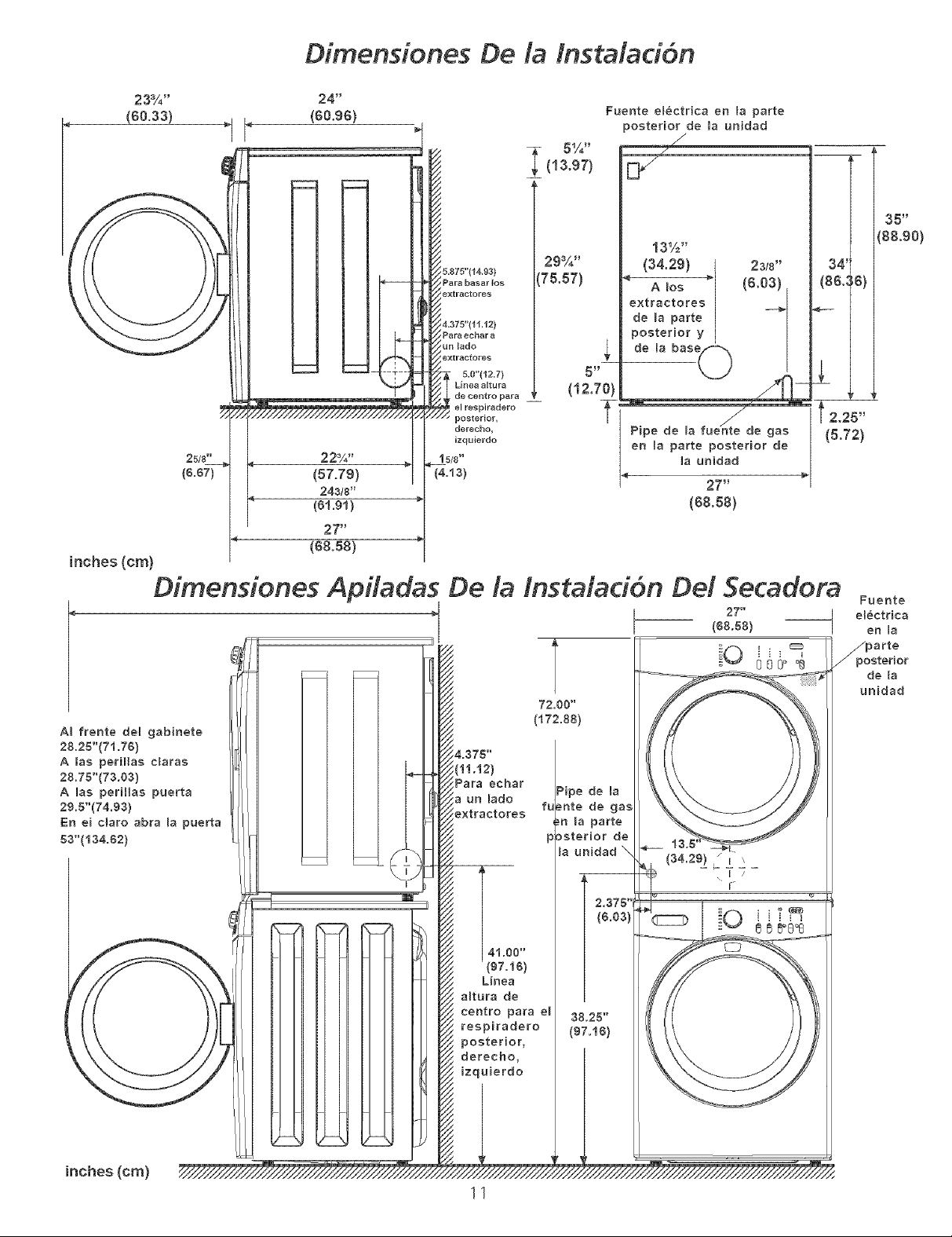
Dimensiones De la tnstMaci6n
23%"
(60°33)
inches(cm)
22%"
(57.79)
243t8"
1_1.91)
27"
(68.58)
&875"114.93 )
Para basar [os
z
!extractores
5.0"112.71
Linea altura
, de centro pare __
I el respiradero
' posterior,
derecho,
izquierdo
1 5/8"
(4.t3)
29%"
175.57)
(12.70)
Fuente e[_ctr[ca en [a parte
posterior de la unidad
/
13½"
(34.29) I 23/8"
_ (6.O3)
e×traeto,es I -÷1
de [a parte I [
de la bas
posterior e(_
5 _
Pipe de [a fue_te de gas (5.72)
en la parte posterior de
T / . t 2,25"
_a unidad
27"
(68.58)
35 _
',88.90)
Dimensiones Apiladas De la tnstalad6n De/Secadora
A_ frente del gabinete
28.25"(71.76)
A tas periHas claras
28.76"(73.63)
A lee peritias puerta
29.5"(74,93)
En ei claro abra [a puerta
63"(i34.62)
/
27 _
(66.58)
iO 0064
72.06"
(172.88)
4.375"
lii.i2)
Pare ether
a un [ado
_xtFaetoFes
[
Pipe de la
_u
_nte de gas
.!n [a parte
p)sterior de
la unidad \
2.375"1
(34.29) _ I \
Fuente
el_ctrica
en [a
_po parte
sterJor
de la
unidad
(&63)
4i.66"
(67.16)
L[nea
a[tura de
centro pare e[
respiradero
posterior,
derecho,
izquierdo
38.25"
(97.16)
inches (cm)
11
Page 12

INSTALA CION EN CASAS MOWLES
1, El tubo de escape de la secadora DEBE ser instalado hacia el
exterior (El escape debe colocarse en la parte exterior y no
debajo de la casa m6vik) Debe usarse ducto de metal que no
sea combustible El ducto de metal debe tenet cuatro
pulgadas (10,16 cm) de di_imetro y no tener obstrucciones_ Es
preferible usar ducto de metal que sea Hgido_
2, Si el tubo de escape de la secadora torte a traves del piso y el
_irea debajo de la casa m6vil es cerrada, el ducto de escape
DEBE terminar fuera del recinto, con el extremo final
asegurado en contra de la estructura de la casa m6vil
3, AI instalar una secadora de gas en una casa m6vil, hay que
instalar una provisi6n de aire fresco suplementario La
provisi6n tiene que set ma's grande que dos veces el espacio
del escape de la secadora_
4, Esta secadora DEBE asegurarse al piso, El juego para
instalaci6n en la casa m6vil es el No, 346764 t' Io puede
adquirir con su distribuidor
5, Vea las p_Sginas 2 y 3 para otros requ[sitos importantes de
ventiJaci6n
6, La instalaci6n DEBE cumpJir con las est_Sndares aplicables de Ja
Manufactured Home Construction & Safety Standard -
Est_Sndares de Seguridad y Construcci6n de Casas
Prefabricadas (TftuJo 24 CFR - Parte 32-80 deJ RegJamento
Federal) o cuando dichos esta'ndares no sean aplicables, se
deben complir con los est_indares de Ja American National
Standard for Mobile Homes (Est_indares NacionaJes
Americanas para Viviendas M6viJes)_
Esta secadora ha sido disenada PARA USO
DOMESTtCO solamente, de acuerdo con Janorma ANSI Z 21,5,1 o
ANSI/UL 2158oCAN/CSA C222 (Jas 0ltimas edici6nes
MODEL OS A UTONOMOS CON CONSOLA
SUPERIOR
DtMENSIONES PARA LA INSTALACI6N
DESEMBALAJE
1, UtiJizando las cuatro esquineras de embarque de Ja caja de cartbn
(dos a cada Jado), coJoque cuidadosamente la secadora sobre el
costado izquierdo y saque la base de espuma de embarque
Para evitar darhos, no use el panel de control como
un medio para Jevantar o mover Jasecadora
2, Vuelva la secadora asu posici6n vertical,
PLACA DE
ESPUMA DE
EMBARQUE
MPAQUE
CORRECTO
i ¸
i ii i _
©
INCORRECTO
12
Page 13

mNSTRUCCIONES DE LA REVOCACION DE LA PUERTA DE LA SECADORA
Use guantes para dar vueIta [a puerta.
1. Abra la puerta de la secadora,
2,
Retire los cinco tornillos, 1 a 5, y los dos tomillos, 6 y 7, que
fijan la parte interior de la puerta a la parte exterior. Levante la
parte exterior y retirela de la parte interior y co!oquela sobre
una superficie plana y lisa.
Retire los dos (2) tota!!los de fijacion de las bisagras y co!oque
la puerta interior sobre una superficie plana y lisa.
5. Retire la bisagra. Girela e inst&lela en el lado opuesto de la
parte exterior.
Retire los dos tomillos que fijan la bisagra al panel frontal.
4. Retire los tornillos que fijan la placa contra golpes, Gire la
placa contra golpes y vuelva a colocada en e! lado opuesto de
la puerta interior,
7. Retire la placa de sujeci6n del panel frontal.
8, Gire y vuelva a instalar la bisagra y la placa de sujecion en los
lados opuestos a los lados de donde las sac6,
9. Vuelva a fijar la puerta en orden inverso,
10, Cierre la puerta,
13
Page 14

INS TALA OON ELL'CTRICA
Secadoras EL_CTR/CAS
Los siguientes requerimientos son espedficos
para et funcionamiento correcto y seguro de su secadora. El
incumplimiento de esta5 instrucciones puede causar prolongad6n
excesiva del dempo de secado y Hesgos de incendio.
ff __ Este artefacto DEBE ser puesto a derra de
manera correcta. Si la secadora no esta debidarn_,nt_, puesta a tierra se
puede producir un cheque el_ctrico. Siga ]as instrucciones indicadas en
este manual para la puesta a tierra en forma correcta.
No use un cordbn de extensi6n con esta
secadora. Algunos cordones de extension no pueden soportar ]a cantidad
de cordente electrica que utiliza esta secadora y pueden fundirse, creando
un pe]igro de cheque ek',ctrico y/o incendio. Ubique la secadora de manera
que el cordon electrico ]legue hasta el tomacomente que se va a usar,
dqando un poco de holgura para el cordon. Consuke los requedmientos
de instalacion preliminares indkados en este manual para el cordon
el_,ctrico que debe ser adquirido,
_f__ $e debe instalar un andaje aprobado per et U.L
para el cordon eMctrico. 5i no se uti]iza un andaje para sujetar el cordon
el_ctrico, g,ste puede salirse de ]a secadora y cortarse con cualquier
movimiento, resultando en un cheque electrico,
No utilice un tomacorriente con cables de
alum#do con un cord6n y un enchufe de cobre (o viceversa). Se
produce una r_,acdOn quimica entre el cobre y el a]uminio que puede
causar cortacircuitos, El cableado y tomacorriente apropiado es un
cord6n el_ctrico equipado con conductores de cobre con un
tomacorriente con conductores de cobre.
NOTA: Lassecadoras que operan con un suministro de energia de 208
vokios usar_n mas tiempo de secado que aquel]as que operan con un
suministro de energia de 240 vo]tios.
REQUERIMENTOS PARA LA PUESTA A TIERRA
TORNIL[O
VERDE DE
PUESTA A
TIERRA
CABLE DE
PUESTA
A TIERRA
NEUTRAL
_ORNE PLATEADO
TUERCA
ESTAS ROSCAS
SOPORTE DE
MONTAJE DEL
ANCLAJE DE
CABLE
CORDON ELECTRICO
CONEXIONE5 ELECTRICA5 PARA
UN SISTEMA TRIFILAR
Secadoras EZECTR/CAS 1
La conc-,xiOnindebida de] conductor de puesta a tb, rra d_q
equipo puede ocasionar un riesgo de cheque e]ectrice. Consuke con un
electdcista profesional si tiene a]guna duda respecto a la puesta a tierra
correcta del artefacto.
Para una secadora puesta a derra, con cord6n el_ctrico:
I. Lasecadora DEBE ser puesta a tierra, Encase de ma]funcior_amiento o
fa]]a, la puesta a tierra reducir_ el riesgo de cheque ebctrico
propordonando un trayecto de menor resistencia a la cemente
e]ectrica.
2. Si su secadora esta equipada con un cordon el#,ctrico que posee un
conductor de puesta a tierra de] equipo y un enchufe de puesta a tierra,
dicho enchufe DEBE ser conectado a un tomacorriente adecuado,
debidamente instalado y puesto a tierra de acuerdo con todos los
cOdigos y regBmentos locales. Si tiene alguna duda consuke a un
electridsta profesional. No modifique el enchufe propordonado la
aplica dbn.
PaYa Una secadoFa cot_ectada _eymanentementer
I. La s_cadora DEBE ser conectada a un sist_,ma de cableado met_lico
permanente, puesto a tierra; o se debe instalar un conductor de
puesta a tierra de equipo junto con los conductores del circuito y
conectarse al borne de puesta a tierra del equipo o al cable del
artefacto.
TODAS/as_ecadorasa GAS i
Estasecadoraestaequipadacon un enchuf_:,detres_,spigas {depuestaa
tbrra/para prot_,ccion en contra de choques el6ctricos ydebe ser conectada
directamenta en un recept_culo para tres espigas _qcua] debe estar puesto
a tierra. No corte ni _qirnine la espiga de pu_,sta a tbrra d_:,este enchufe.
SecadorasEZECTR/CAS
1, Saque los tornillos que sujetan la cubierta de acceso del tablero
de bomes y el soporte de montaje del anclaje del cord6n,
situado en Jaesquina superior de Japarte trasera de Jasecadora,
2, Instale un anclaje de cable aprobado per el UL, en el orificio de
entrada del cord6n elOctrico en el soporte de montaje Luego
apriete Jatuerca con los dedos solamente
3. Inserte un cord6n el@ctricode 30 amp, NEMA 10-30 Tipo SRDT,
aprobado per el UL, a trav@sdel anclaje de cable,
4, Conecte el conductor neutro del cord6n el@ctrico(cable central)
al borne central plateado del tablero de bornes, Apriete
firmemente el tornillo
Conecte los dos conductores externos restantes del cord6n
elOctrico a los bornes bronceados externos del tablero de
bornes Apriete firmemente los tornillos,
_,aa_,ua£k_r±_ No doble en forma pronunciada ni engarce
los cables/conductores en las conexiones
6, Coloque nuevamente el soporte de montaje deJ ancJaje de cable
en Ja parte trasera de la secadora con dos torniHos, Apriete
firmemente los tornillos,
7. Apriete firmemente los tornillos del anclaje de cable contra el
cord6n el_ctrico,
8. Apriete latuerca del anclaje de cablea fin de que el anclaje no
gire
9. Coloque nuevamente la cubierta del tablero de bornes
14
Page 15
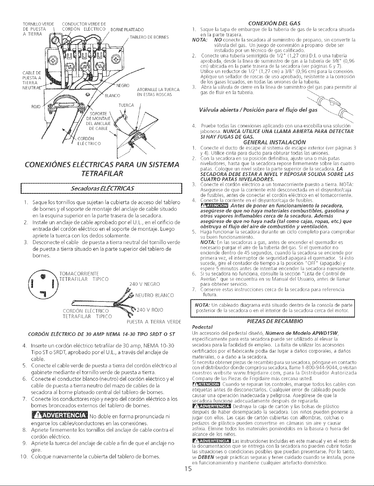
TORNILLOVERDE CONDUCTORVERDEDE
CONEXIONES ELL'CTRICAS PARA UN SISTEMA
TETRAHLAR
Secaderas EL#CTR/G4S
1. Saque los tornillos que sujetan la cubierta de acceso del tablero
de bornes y el soporte de montaje del anclaje de cable situado
en Ja esquina superior en Japarte trasera de la secadora.
2. Instale un anclaje de cableaprobado por el UL, en elorificio de
entrada del cordon eJOctrico en el soporte de montaje. Luego
apriete Jatuerca con los dedos soJamente_
3. Desconecte el cable de puesta a tierra neutral del tornillo verde
de puesta a tierra situado en la parte superior del tabJero de
bornes
CONEXION DEL GAS
I. Saque ]a tapa de embarque de la tuberia de gas de ]a secadora situada
en la parte trasera.
NOTA: NO conecte la secadora al suministro de propano, sin convertir la
2. Conecte una tuberia semirigida de 1/2" (1,27 cm) DI. o una tubeda
3. Abra la valvula de cierre en B linea de suministro del gas para permitir al
4. Pruebe todas las conexiones aplicando con una escobilla una soluciOn
I. ¢onect_, _,1ducto de _,scape a[ sistema de _,scape exterior (vet p_ginas :_
2. Con la secadora en su posiciOn definitiva, ajuste una o mas patas
5. Haga funcionar la secadora durante un ciclo ¢ompbto para ¢omprobar
6. Si su secadora no funciona, consulte la secciOn "Lista de Control de
7. Conserve estas instrucciones cerca de la secadora para relerenda
valvula del gas. Un juego de conversion a propano debe ser
instalado por un tecnico de gas calificado.
aprobada, desde la linea de suministro de gas a la tubeda de €/8" @,96
cm) ubicada en la parte trasera de la secadora (ver paginas 6 y 7),
Utilice un reductor de I/2" (1,27 cm) a 3/8" (0,96 cm) para la conexion.
Aplique un sellador de roscas de uso aprobado, resistente a la corrosion
de los gases Iicuados, en todas hs uniones de la tuberia.
gas de fiuir en la tubeda.
V_lvuta abierta / Posici6n para el flujo del gas
jabonosa. NUNCA UTIMCE UNA LLAMA ABIERTA PARA DETECTAR
SI HAY FUGA5 DE GAS.
y 4), Utilice cinta para ducto para obturar todas las uniones.
niveladores, hasta que la secadora repose firmemente sobre las cuatro
patas. Coloque un nivel sobre la parte superior de la secadora, LA
SECADORA DEBE ESTAR A NIVEL Y REPOSAR 50MDA 50BRE LAS
CUATRO PATAS NIVELADORES.
Conecte _,1cordon electrico a un tomacorriente pu_-,stoa tierra, NOq7_,:
Asegorese de que [a corriente este des¢.onectada en el disyuntor/caja
de fusibles, antes de conectar el cordon electrico en el tomacorriente.
Conecte la corriente en el disyuntor/caja de fusibles,
aseg_rese de que no haya materiMes combustibles, gasofina y
etros vapores inflamabtes cerca de la secadera. Adem4s
asegOrese de que no haya nada (tM como cajas, ropas, etc) que
obstruya el flujo del aire de combusd6n y ventiladbn,
su buen funcionamiento.
NOTA: En las secadoras a gas, antes de encender el quemador es
necesario purgar el aire de la tuberia del gas. Si el quemador no
enciende dentro de 45 segundos, cuando la secadora se enciende por
primera vez, el interruptor de seguridad apagara el quemador, Si 6sto
sucede, gire el contador de tiempo a la posicion "OFF" (apagado) y
espere 5 minutos antes de intentar encender la secadora nuevamente.
Avedas" que se encuentra en su Manual del Usuario, antes de Ilamar
para obtener servicio.
futura.
GENERAL iNSTALAC/ON
Antes de poner en fundonamiento la secadora,
PUESTAA TIERRA VERDE
CORDON ELECTR/CO DE 30 AMP NEMA 14-30 TIPO 5RDT 0 5T
4 Inserte un cord6n elOctrico tetrafilar de 30 amp, NEMA 10-30
Tipo ST o SRDT, aprobado por el U_L, a tray,s del anclaje de
cable.
5 Conecte el cable verde de puesta a tierra del cordon elOctrico al
gabinete mediante el tornillo verde de puesta a tierra_
6 Conecte el conductor blanco (neutro) del cordon electrico y el
cable de puesta a tierra neutro del mazo de cables de la
secadora al borne plateado central del tablero de bornes_
7 Conecte los conductores rojo y negro del cordon elOctrico a los
bornes bronceados externos del tablero de bornes
No doble en forma pronunciada ni
engarce los cabJes/conductores en Jasconexiones
8 Apriete firmemente los tornillos del anclaje de cable contra el
cordon elOctrico_
9 Apriete la tuerca del andaje de cable a fin de que el anclaje no
gire.
10 Coloque nuevamente la cubierta del tablero de bornes
NOTA: Un cableado diagrama esta situado dentro de la consola de parte
posterior de la secadora o en el interior de la secadora cerca del motor,
PEZA5 DE RECAMBIO
PedestM
un accesorio de] pedestal diset_O, NOmero de Medeto APWD15W,
_,spe:ificamente para esta secadora puede ser utilizado al ebvar la
secadora para la facilidad de empleo. La falta de utilizar los accesorios
certificados por el fabricante podia dar lugar a dat_os corporales, a dat_os
materiales, o a dano a la secadora.
Si nec_-,sitaobtener piezas de recambio para su secadora, p6ngaso, en contacto
con el distribuidor donde compr0 su secadora, Ilame 1-800-944-g044, o visitan
nuestros website www.frigidaire.com, para la Distribuidor Autorizada
Company de las Piezas de Frigidaire mas cercana usted.
Cuando se reparan los controles, marque todos los cables con
etiquetas antes de desconectados. Cualquier error de cableado puede
causar una operacion inadecuada y peligrosa. AsegOrese de que la
sr<adora funcione adecuadamente dr:,spuOs de reparada.
Destruya la caja de carton y las bolsas de pBstico
despu_'_sde haber desempacado la secadora Los nitros pueden ponc,rse a
jugar con ellos. Las cajas de carton cubiertas con alfombras, colchas o
pedazos de pBstico pueden conv_-,rtirse en camaras sin aire y causar
asfixia. Elimine todos los materiales poniOndolos en la basura o fuera del
alcance do, los ninos.
F_J__ Las instrucciones incluidas en 6,stemanual yen el resto do_
la documentation que se entrega con la secadora no pueden cubrir todas
las situaciones o condiciones posibles que puedan preso,ntarse. Por Io tanto,
se DEBEN seguir practicas seguras y tener cuidado cuando se instala, pone
en funcionamiento y mantiene cualquier artelacto domOstico
15
 Loading...