

Page 1
WALLSLEEVE INSTALLATION INSTRUCTIONS FOR
FRIGIDAIRE
THRU-THE WALL AIRCONDITIONERS
READ AND SAVE THESE INSTRUCTIONS
MMMm
--------------------------
To avoid risk of personal injury, property damage, or
product damage due to the weight of this device and
sharp edges that maybe exposed:
•Airconditioners covered in this manual pose an
excessive weight hazard. Two or more peopleare
needed to moveand install theunit.
To prevent injury or strain, use proper lifting and
carrying techniques whenmoving unit.
• Carefully inspect location where air conditioner will
be installed. Be sure it will support the weight of the
unit overan extended period of time.
•Handle air conditioner with care. Wear protective
gloves whenever liftingor carrying theunit. AVOID
the sharp metalfins offront and rearcoils.
• Make sure air conditioner does not fall during
installation.
For New Construction install Frigidaire Wall Sleeve
(Part EA108T).
Remove old air conditionerand inspect sleeve forthe
following:
Installation - Make sure that sleeve is securely
installed and in sound structural condition.
Dimensions-Measure the size to make sure the air
conditioner will fit.
Slope-There should be a rearward slope for
condensate to drain from the rear of the sleeve.
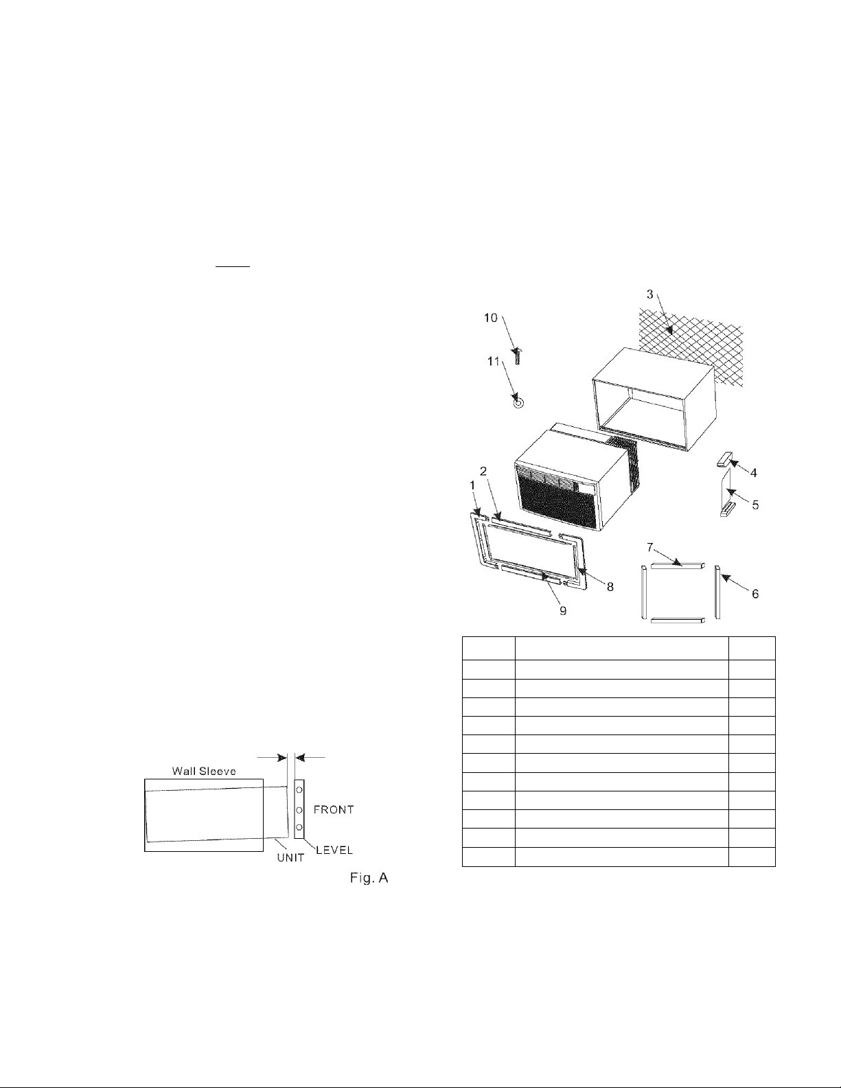
Check against Fig. A.
1/4” to 5/16”
REAR
Check the contents of the accessories supplied with
your air conditioner as shown below:
Number Part name QTY.
1
2
3
4
5
6
7
8
9
10 Screw
11
Top/Bottom Trim Frame
Side Trim Frame
Plastic Mesh
Tapered Spacer Block Board
Tapered Spacer Block
Vertical Foam
Horizontal Foam
Vertical Trim Foam
Horizontal Trim Foam
Washer 4
2
2
1
2
1
2
2
2
2
4
Manufacturer-So the method of installation can be
determined.
If the installation and slope are suspect, then removal
and correct installation of a Frigidaire Wall Sleeve
(Part EA108T), is recommended.
P/N:819042236-01
Page 2
IN STALLATI ON
HOW TO INSTALL
1. Identify the existing wall sleeve before installing
the unitfrom the listed below.
Brand
White-Westing house
Frigidaire
Carrier(52F series)
General Electric
/Hotpoint
Whirlpool
Fedders/Emerson
Sears/Kenmore
Carrier(51 S series)
Emerson/Fedders
Friedrich
NOTE: All wall sleeves used to mount the new Air
Conditioner must bein sound structuralcondition and
have a reargrille that securely attaches to sleeve, or
rear flange that serves as a stop for the Air
conditioner.
Wall SleeveDimensions(inches)
Width Height Depth
25-1/2 15-1/4
26 15-5/8
25-7/8 16-1/2
27 16-3/4
25-7/8 15-17/32
25-3/4 16-7/8
26-3/4 15-3/4
27 16-3/4
16, 17-1/2
16-7/8
17-1/8
or 23
16-3/4
or 19-3/4
16-23/32
18-5/8
15
16-3/4
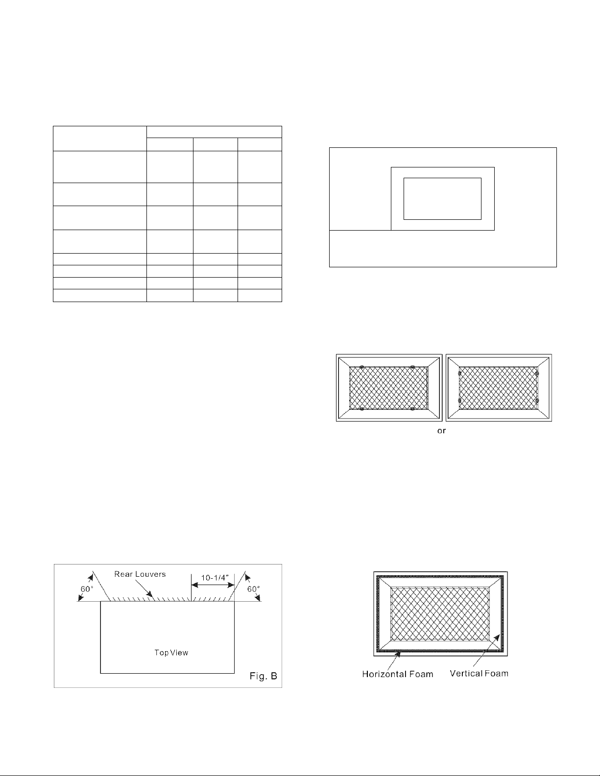
5. If the wall sleeve already has a reargrille, skip to
step 7. If the wall sleeve does not have a rear grille or
louvered panel, install the plastic grille from the kit.
Cut the plastic mesh to match the sleeve installed.
Place the plastic grille to the inside of the wall sleeve
at the rear flange.
\
Place the plastic grille
y
Fig. C
6.Use the 4washers and screwsto secure thegrille to
the wall sleeve.
2.Clean the interior of the sleeve (do not disturb
seals).
3.Repaint the sleeveif needed.
4.Redirect the louversat the backof the wallsleeve to
60 angle as shown in the Fig.B. The use of pliers is
recommended.
Fasten the screws
/.Remove the backing from the Vertical Foam and
attach thatto the insideright of the sleeve as shown
below.
Remove the backing from the HorizontalFoam and
attach thatto the insidefront of the sleeve as shown
below.
Fig. D
Fig. E
Page 3
IN STALL. ATI ON
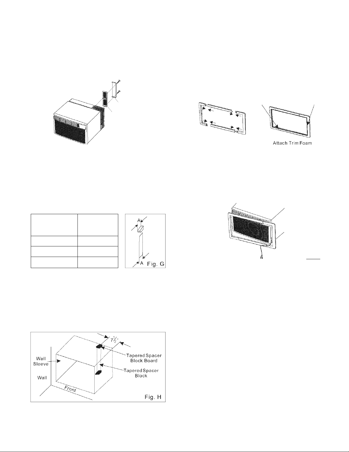
8. If you wish to keep the unit be operated at higher
performance state, remove the steel rear grille and
attach the plastic rear grille. The plastic grille will
minimize the recirculation of hot discharge air.
Plastic rear grille
Steel rear grille
Fig. F
9.If thedepth ofyour existing wall sleeve is less than
or equal to 20”, skip to step 11. Otherwise, cut the
baffles and the support blocksaccording to length “A”
in thetable below.
Depth “D” of the
existing wall
sleeve (inches)
Length “A”
(inches)
11 .Install the new unit into the wall sleeve.
12.To assemble trim, snapthe tab ofeach piece into
the slot of the other piece as shown below. Remove
the backing from the trim foam and stick thatto the
inside of the trim as shown below.
Horizontal
Trim Foam
Assemble Trim
Vertical
Trim Foam
Fig. I
12.Slide trim over thefront ofthe airconditioner until
trim isflush with sleeve as shown below.
20<D^20^g
2 0% < D ^2 ^ %
21^<Di24 4
10.Remove the backing from the support blocks and
attach them to the inside ofthe wall sleeve as shown
FIG H. Slide the baffle into slotsof thesupport blocks.
%
1-^/4
_____________________^_____________
NOTE: Be sure to route the cord through the trim
frame before placing the trim frameon the unit.
•Air conditioners covered in this manual pose an
excessive weight hazard. Two or more people are
needed to moveand install theunit. To prevent injury
or strain, use properlifting and carrying techniques
when moving unit.
• When handling the air conditioner, be careful tc
avoid cuts from sharp metal fins onfrontand rear
coils.
• Make sure air conditioner does not fall during
removal.
Fig. J
 Loading...