

Page 1

(26)- (417/FRIGIDAIRE) FRONT LOAD WASHER DOOR
BOOT #5303937140 REPLACEMENT PROCEDURE
Page 2
rilMBl.F \rT10N WASHER
PRO BI. P. M: PROCKiniRE FOR REPi AC ING THE BOOT
Replacaiitmi of the BOOT on the Front Load Tumble -\ction Washer is to man> technicians, a job best
avoided at all costs Sooner or latei you will be confronted by this |ob and with a little preparation undei
your belt >ou may be pleasantly surpnsed to learn that it is easier than anticipated
This tutoi lal will show you how to do the job, what pitfalls to avoid and will include some great tips
1)
2)
if the machine has a Dryer stacked on top of it or is positioned m such a way that it would be
too much bother to move, you will be better off leaving it wliere it is
However, if it is possible, it wxuild be easier to do this job if the machine could be leaned
back against a wall (protect the w'alt against being defaced though) By leaning it back, the
tubs will hang back from the (non-removable) front panel and you will have increased space
to work
If leaning It back is not possible, then a 6 or 8 inch block of wood will be handy to use to
wedge between the front panel and the tub to hold the tub back out of the way
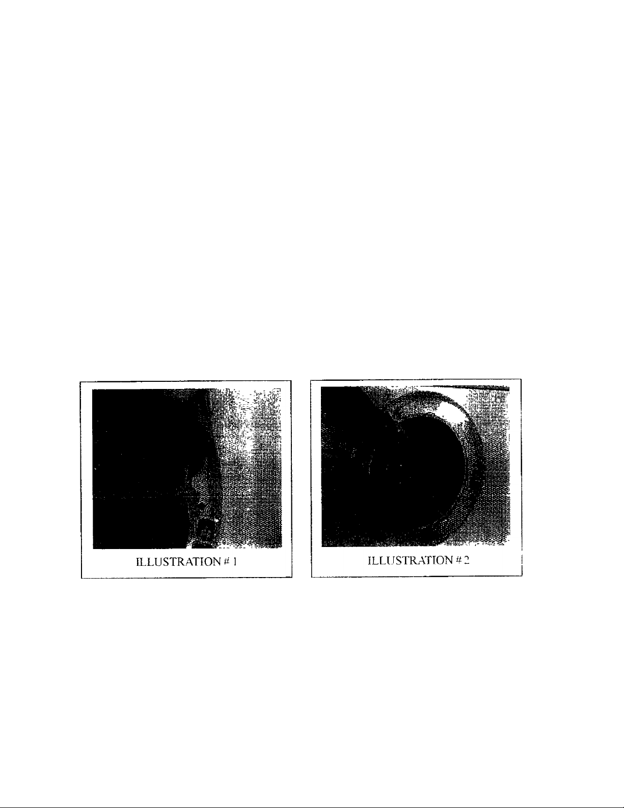
The boot IS attached to a hp aiound the perimeter of the opening in the front paneland is
glued on m spots about thiee inches apart, all the way around Use a razor blade as shown in
illustration #l to carefully slice the glued spots on the boot away from the front panel
4)
Once the boot is loose from the front panel, push it into the opening of the tub and out of the
way as shown in number 2 At this point, if the machine is not leaning back, take youi block
of wood and while pushing back on the tub through the opening, wedge the block between
the front panel and the tub about ten inches to the bottom - right of the opening This will
aflbrd you more space to work with the boot
You will novv notice that the boot is still attached to the duct that is located |ust inside the
front panel at the upper left coi ner from the opening This is where the water, soa[t, bleach
and fabric softener entei the tub
To lemov e (and latei on reattach) the clamp holding this in place on the end of the duct you
will have to make vouiseif a tool fiom a three inch piece of3/8 inch soft copper (ubms:
i cbm II
Page 3

FRONT LO-VL> WASHER
PROC EDI RK FOR REPLACING THE BOO I' contmued
4)
In illustration W} \ou will see that the end of the tube is flattened somewhat so that it can be
slipped over the twisted ends of the clamp as shown in illustration tf 4
nj. USTRATION #
fwist the tube counterclockwise to slip the clamp and set both the tool and the wire clamp
aside Pull the boot free from the duct
Usinii both hands, grab onto the boot at the top ofthe opening to the tub and pul! downw'ard
and tow aid you with slow steady pressure As the boot is pulled free from the outer lip ofthe
tub (at the top), the coiled spnng that holds the boot from the groove behind the hp around
the opening to the front shell will become visible You can either continue pullmg on the
boot until It comes off or you can hook the spring (with a piece of coat hanger fashioned into a
hook) and pull it off and then pull the boot oif separately
6)
Once the boot is off, examine the hp that extends around the entire penmeter of the front
opening of the fiont shell of the tub (the front shell and the rear shell are so named because
when bolted together fonn the outer tub that sun ounds the inner tub)
The boot has a hp that will have to be folded into the gtoov'e behind the hp on the front shell
To start tins, examine the new boot and locate the groove m front ofthe lip that corresponds
to the similar lip and tab on the tub shell It will make this job a lot easier if you can
obtain some liquid dishwashing soap from the consumer, and spanngly lubncate this groove
on the boot to make it easier to slip onto the lip of the shell (see illustration # 5 on next
page)
No soap Is piefei able to too much soap Hav e a vloth handy to wipe the soap from voui
lingei s
Page 4

ì: kONI LO VDW VSHKR
i ki ì)URF FOR RFPl VONG IHEBOOl amiinued
S',
ILLUSTRATION #5
ILLUSTRATION #6
Once the groove in the boot is lubed with soap, locate the arrow as shown m figure #6 that
IS located on the top of the boot (located to the right of the extrusion that slips over the duct}
This arrow must point up when the boot is installed
With the boot in one hand and the other hand spreading the lip and groox'e (on the boot near
the arrow}, force the lip into the groo\'e behind the lip at the top of the opening on the ttih
shell (see figure ti7}
With one hand holding the boot so it does not slip olf, use the other hand to continue
spreading the hp and groove of the boot further to the right In this way you continue this
action j60 degrees aiound until the boot is mounted onto the front shell (see # 8)
Vom fingers will take a beatiti” while von do this and may become quite tired Don't give up
Rest one hand at a lime if needed V\ hate\ ei vou do, do not remove both hands until the
bool is on ( unless you want it to fall otl'and then you get to start over w'lth il )
I I 'll.ir'
Page 5

KRÖNT LOA» WASHER
PRÜCEOliRE FOR REPE VCING THE BOOT continued
I")
Now IS the tune to pul the spring bAck on Included in the BOOT KIT is a set ofthree spacei ^ (an
example ofw hich is shown in # 9 below) These spacei s are to be used to hold the spring in place
in the groove on the outside perimeter of the boot As it will take both hands to stretch this spring
into place, these spacers will pievent the spnng from popping out when you let go of it ro use both
hands to stretch it hirther around the boot
Begin by pushing the spring down into the groove just forward from where the boot contacts the
front shell at about the 12 o’clock position Wlule holding it in place with one hand. Use the other
to tightly W'edge the spacer abo\'e it, between the spnng (in its groove) and the weight nng above it
as show'ti in illustration 10
^ :-Г‘, - -
И)
U)
П)
ILLUSTRATION #9
ILLUSTIUATION it 10
Working your w av to the nght, push the spnng down into the groove When you ha\'e placed
the spring about 90 degrees around the opening from the first spacer, the spring will begin to
get tight Push m another spacer at that point (making sure to keep checking the first spacer,
if It pops out - the spnng will pop out)
Continue w'orkmg your way around (while checking both spacers, you don’t want them
to slip out) until you reach 180 degrees
from the first spacer Install the third
spacer
The spring w ill be extremely tight now as
bhow'ii m # 11 to the i ight Once you have
gone more than halfway around, the spnng
will be easier to roll into the rest of the
groo\e (so long as all three spacers are
holding tight) When you have the spring
m place make мне to i emo\o the three
spacei s before proceeding to step ti 14
1 eh>i 1 lar'
Page 6

FRONT LOVOW vsnfc:R
PROCEDI RE FOR REPLNCTNG THE BOO I coiumued
!4)
1^)
Replace ihe hoot e\taision back onto the
duct and pull it up ovei the ndge on the
duct neat the top ot'the opening
Reinstall the clamp in such a way that the
clamp sits between the ridges on the
extrusion and abo\'e the ndge on the duct
Snap the clamp closed with the copper
tubing tool that \’ou used preuously
Before attaching the new boot to the front
panel, clean the suiTace of the front panel
with alcohol or household cleaner Also
clean the flat surface of the new boot that
will be contacting the front panel This
step IS needed to remove the mold release material used in the manufactunng process and will allow
the adhesive to stick
16) Remount the boot onto the front panel as
or counter clockwise as needed
ILLUSTRATION# 12
shown in figure #13, making sure that
the boot is not wTinkled Iflarge wrinkles
exist, they may pool water in the boot and
dribble onto the floor w hen the door is
opened
[fthis IS the case, pull it loose from the front
pane! and remount it slightly more clockwise
17)
Using the adhesive supplied in the kit,
sparingly apply dots of glue under the edge
of the boot as shown in # 14
Spot glue at the 1 2 o’clock, 1. 2. 3, 4, 5 6,
7, 8 and 9 o'clock positions around the
opening
ILLUSTRATION# 14
Caution the consumer to wait a couple of
hours before using the washer to allow the
adhesive enough time to dry
! rliiii II
 Loading...