

Page 1
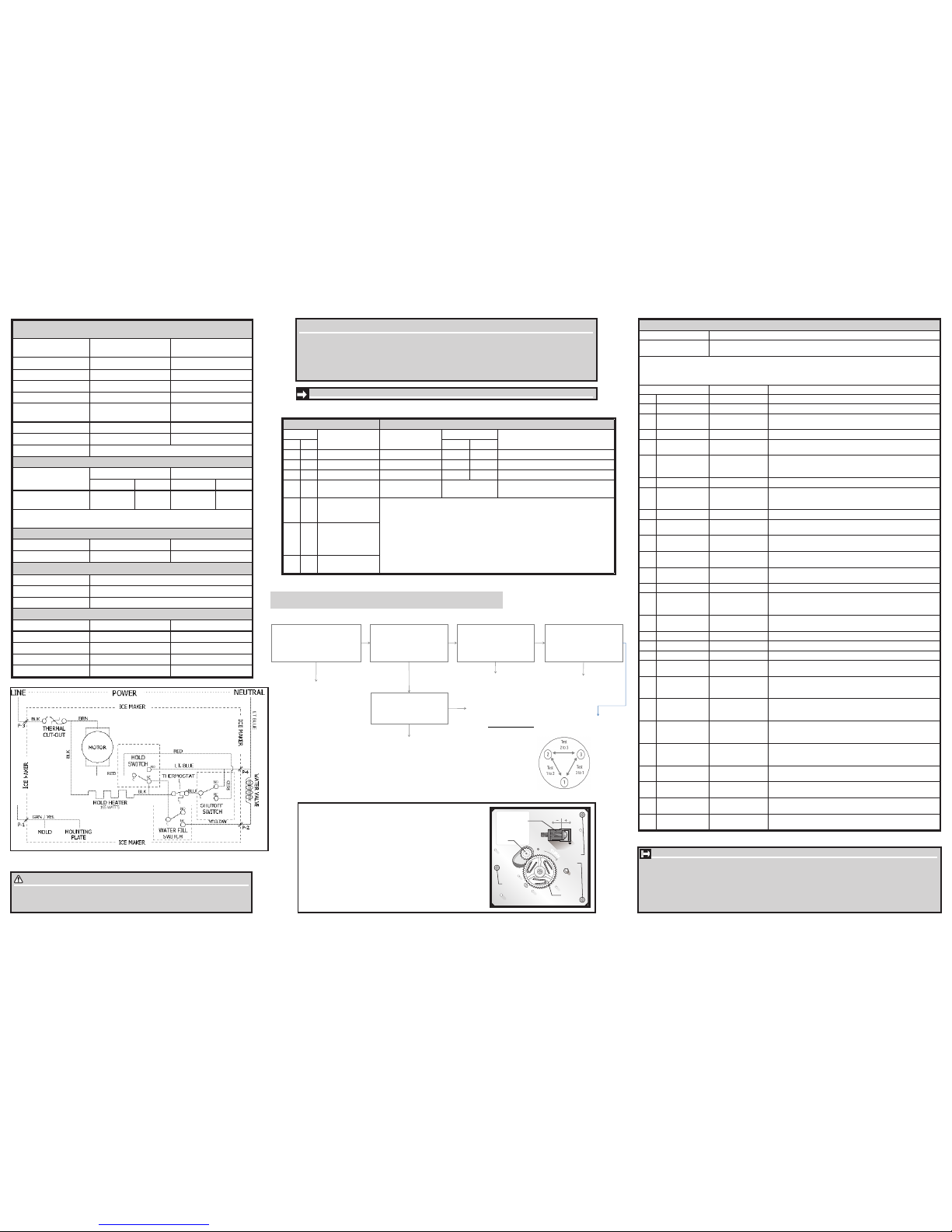
SERVICE DATA SHEET
242292200
ICE & WATER - AUTOMATIC DEFROST
BOTTOM FREEZER - R134a
CAUTION
All electrical parts and wiring must be shielded from torch flame. DO NOT allow torch
to touch insulation; it will char at 200°F and flash ignite (burn) at 500°F. Excessive
heat will distort the plastic liner.
PERFORMANCE DATA NO LOAD & NO DOOR OPENINGS AT 37°/0°
CONTROL SETTING
Type A with Run / Start
Capacitor
65°F (18°C) Ambient 90°F (32°C) Ambient
Operating Time
90 to 100% 100%
Freezer Temperature -5° to 2°F (-20° to -17°C) -1° to 3°F (-18° to -16°C)
Refrigerator Temperature 34° to 39°F (1° to 4°C) 34° to 39°F (1° to 4°C)
Low Side Pressure -2 to 6 psig ( -14 to 41 kPa) -2 to 6 psig (-14 to 41 kPa)
High Side Pressure (last 1/3
cycle)
85 to 105 psig (586 to 724 kPa) 120 to 135 psig (827 to 931
kPa)
Wattage (last 1/3 cycle) 30 to 50 50 to 70
Amps (running)
.4 to .8 .7 to .9
Base Voltage 115 vac (127 vac max)
DEFROST SPECIFICATIONS
Cabinet Size
Thermostat Heater
Cut-in Cut-out Watts Ohms
26’ & 28’ SD, 23’ CD
25°F (-4°C) 47°F
(8°C)
500 26.5
Electronic Timer - (ADC) Defrost 24 minutes every 6-96 hours of compressor run
time.
CONDENSER FAN MOTOR
Watts RPM Amps
3.1 1100 CW Opposite Shaft 0.03 Running
FREEZER ICE MAKER SPECIFICATIONS
Electrical 115 vac (127 vac max)
Thermostat Opens at 48°F ( 9°C), Closes at 15° F ( -9°C)
Heater Voltage 115 vac
FREEZER ICE MAKER CONNECTOR PLUG CONNECTIONS
Wire Number Wire Color Connects to:
1 Green / Yellow Ground
2 Yellow Water Valve
3 Black Line
4 Light Blue Neutral
IMPORTANT SAFETY NOTE
The information provided herein is designed to assist qualified repair personnel only. Untrained persons should
not attempt to make repairs due to the possibility of electrical shock. Disconnect power cord before servicing
this appliance.
IMPORTANT
If any green grounding wires are removed during servicing, they must be returned to their original position
and properly secured.
System Diagnostic Mode
Activate:
Press ٨ and ٧ for up to 10 sec. simultaneously.
Deactivate:
Press + for up to 10 sec. Diagnostic Mode will automatically deactivate after 5 min. of inactivity.
Note: Silence alarm.
• Tests marked with “*” may not be applicable to this unit and will not be displayed in System Diagnostic Mode.
• Tests displayed in diagnostic mode but not described below are for internal purposes only; advance through.
• View UI display for “on,” “off,” “CL,” “OP,” “SH,” “LO,” “HI” or numerical results of tests.
• Listen for operating sounds; feel for heat or air ow as appropriate to determine results of tests.
Test To activate test: Passing result
-- First Screen -- All LED lights on UI illuminated
-- Second Screen -- All segments on UI temperature displays illuminated
-- Third Screen -- Blank UI display, no lights illuminated, no shadowing; “-” and “+”
blinking on FF display side to show location.
28 Dispenser Paddle Press disp. paddle “on” on UI when depressed; “off” when released
1* Standard
Compressor
Set Compressor running when “on”; stopped when “off”
2 Defrost Heater Set Defrost limit switch must be closed; verify “CL” in test 26.
Feel for heat from defrost heater when “on”.
If “OP” in test 26, heater will not activate.
3 FF Light Set With FF door open, FF lights on when “on”; off when “off”
8 Water Valve
(Dispenser)
Set FF door must be closed.
Be prepared to collect water at dispenser.
Water dispenses when “on”; stops when “off”
9 FZ Light Set With FZ door open, FZ lights on when “on”, off when “off”
10 Auger Motor Set FF door must be closed.
Motor running when “on”; motor stopped when “off”
11 Cube/Crush
Solenoid
Set FF door must be closed. Do not leave solenoid in activated state.
Solenoid activated when “on”; deactivated when “off”
41* Perfect Temp
Drawer (PTD)
Set PTD UI illuminated when “on”, off when “off”
12* VCC Condenser
Fan
Set Fan running when “on”; stopped when “off”
38* VCC Compressor Set Compressor running when “on”; stopped when “off”
15 Evaporator Fan Set Fan running for minimum of 10 sec. when “LO” or “HI”; stopped when
“off”. Feedback failure if fan starts but runs less than 10 sec. Listen for
speed change from “LO” to “HI”.
36 Ice Chute Door Depress ice chute
door or set
“OP” on UI when manually opened; “CL” when closed. Or, using “power
on-off”, “OP” on UI when solenoid activated, “CL” when deactivated
22 Damper Set With inspection mirror, observe damper open when “OP”; closed when “CL”
23 FF Door Open/close FF door “CL” on UI when door closed; “OP” when open
24 FZ Door Open/close FZ door “CL” on UI when door closed; “OP” when open
26 Defrost Limit Switch Activates automati-
cally
“CL” on UI when closed; “OP” when open
29 FF Thermistor
Mid-level
Activates automatically
UI shows temperature sensed by FF thermistor; pass if within 10°F of
temperature measured with gauge at mid-level FF thermistor location.
“OP-” if open; “SH-” if short
30 FZ Thermistor Activates automati-
cally
UI shows temperature sensed by FZ thermistor; pass if within 10°F of temperature measured with gage at FZ thermistor location.
“OP” if open; “SH” if short
33 Ambient Thermistor
@ Main Board
Activates automatically
UI shows temperature sensed at main board; pass if within +20°F/-
10°F of temperature measured with gauge at main board location.
“OP” if open; “SH” if short
35* FF Thermistor
Upper-Level
Activates automatically
UI shows temperature sensed by upper level FF thermistor; pass if
within 10°F of temperature measured with gauge at upper-level FF
thermistor location. “OP¯” if open; “SH¯” if short
34* Ambient Thermistor
@ UI
Activates automatically
UI shows temperature sensed at UI; pass if within +20°F/-10°F of temperature measured with gauge at UI location. “OP” if open; “SH” if short
0- Firmware
Parameters
Set Displays digit sequence; record
2- Main Board
Firmware
Set Displays digit sequence; record
4- UI Firmware Set Displays digit sequence; record
Variable Capacity Compressor (VCC) Diagnostics (select models)
If test 38 fails, diagnose as follows:
Replace Inverter Board
→ Check at Inverter Board on
Compressor
(BLK and RED wires)
Is Inverter Board receiving 10-15
VAC and 1-5 VDC from Main
Control Board?
→ Check at Main Control Board
(BLK/WHT and RED/BLK wires)
Is Main Control Board sending
10-15 VAC and 1-5 VDC to
Inverter Board?
no
→ Check at the connector from the power cord
harness into the inverter board, located in
the machine compartment.
(PUR and WHT wires)
Is Inverter Board receiving 115 VAC
from power supply?
• Check voltage supply.
• Check and repair power
cord harness wiring and
connections.
no
Identify and repair damaged wires or
poor connections between Main Control
Board and Inverter Board.
yes
→ Remove inverter box from the
compressor and check resistance
across compressor winding pairs as
shown.
Is resistance across all winding
pairs equal?
Replace Compressor and
Inverter Board.
no
→ Check connections from Inverter
Board to Compressor
Are connections from Inverter
Board to Compressor intact?
yes
Identify and repair damaged
wires or poor connections
between Inverter Board and
Compressor.
no
VCC Resistance Check
Check resistance between terminals 1 and
2, 2 and 3, 3 and 1.
If all resistances are equal,
compressor is operative.
Replace Main Control Board.
no
yes yes
yes
Error Codes Special Modes
Display
Interpretation Mode
Display Activate/Deactivate
(press for up to 10 sec. simultaneously)
FZ FF FZ FF
-- OP Open FF Thermistor Manual Defrost d F + and - / same to deactivate
OP -- Open FZ Thermistor Display / Showroom 77 77 ٨ and - / Power-on-Reset (POR)
-- SH Shorted FF Thermistor Sabbath Sb Sb ٧ and + / same to deactivate
SH --
Shorted FZ Thermistor System Diagnostic No FF or FZ dis-
play, all UI LEDs on.
٨ and ٧/ + to deactivate
SY CF
UI to Main Control
Board communication
failure; on start up
Notes:
• Always check for pin back-outs, pinched or damaged wires before replacing
components.
• Determine whether failure is caused by the component, main control board or
wiring. Contact TID before replacing main control board.
• Refer to Service Manual for additional information.
SY CE
UI Main Control
Board communication
error; after a period
in operation
SY EF Evaporator Fan
Failure
IMPORTANT: PLEASE RETURN THIS SHEET TO ITS ORIGINAL LOCATION.
FREEZER ICE MAKER INFORMATION
(Where Applicable)
Test Cycling: Remove cover by inserting screwdriver in notch at bot-
tom and prying cover from housing. Use screwdriver to rotate motor
gear counterclockwise until holding switch circuit is completed. All
components of ice maker should function to complete the cycle.
Water Fill Volume: The water fill adjustment screw will change the
fill time. One full turn is equal to 20cc (.68 oz.). The correct fill is
102 to 130cc (3.4 to 4.3 oz.). When a water valve is replaced, the
fill volume must be checked.
T
U
R
N
Mounting
Plate
Screws
Mounting
Plate
Screw
Motor
Gear
Timing
Gear
Water Fill
Adjustment
Page 2
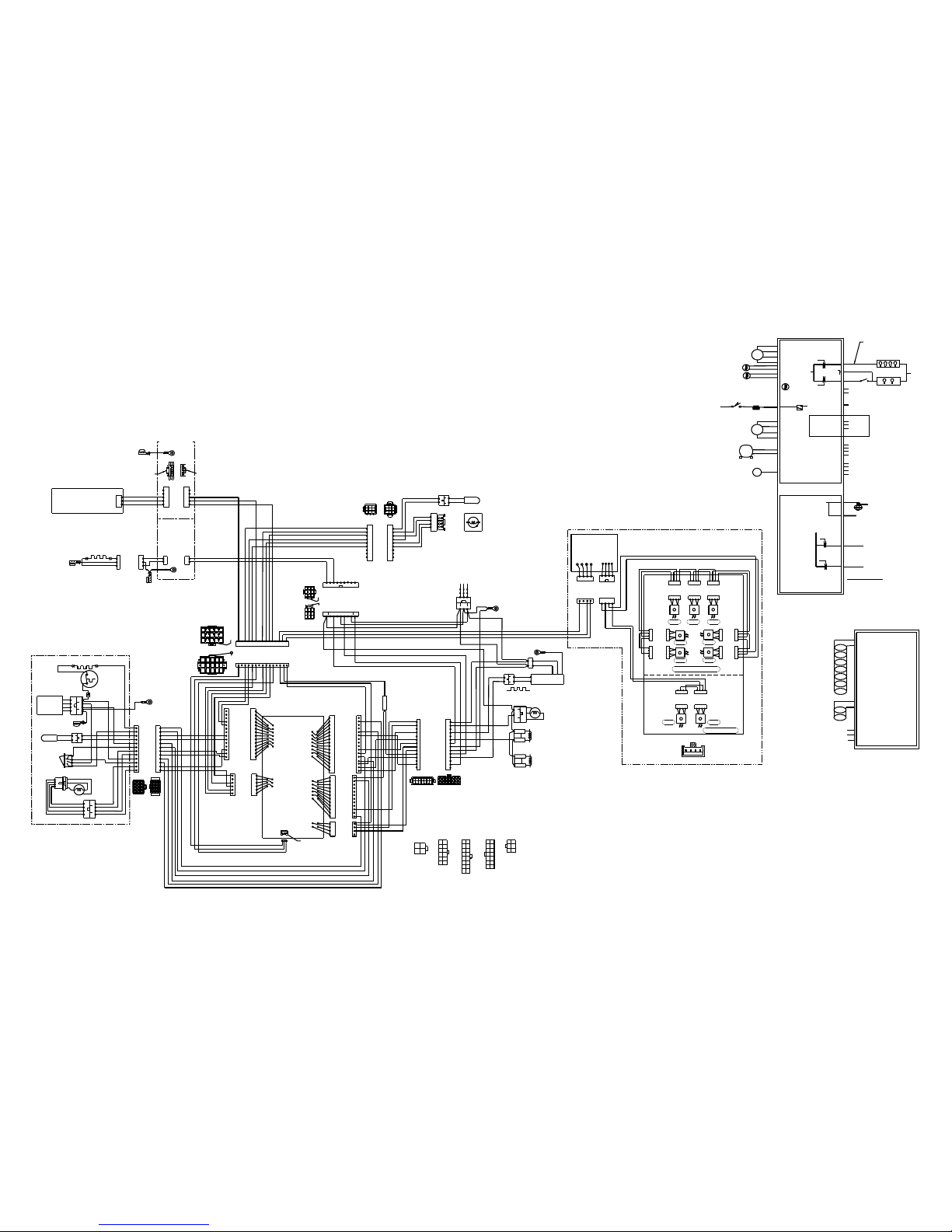
FLIP MULLION HEATER
2
1
MULLION
GROUND
LT. BLU/BLK
GRN/YEL
LT. BLU/WHT
RIGHT
DOOR
GROUND
RIGHT
DOOR HINGE
GROUND
2
1
LT. BLU/BLK
CAB-DOOR
CONNECTIONS
2
1
3
4
WHT
BLK
J2
GRY/WHT
GRY/WHT
FREEZER THERMISTOR
BRN
BLU
YEL
RED
FRZR
FAN
(DC)
DEFROST HEATER
BLU
DEFROST
THERM.
GRY/BLK
GRY/BLK
FRESH FOOD THERMISTOR
DAMPER
MOTOR
RED/YEL
BRN/YEL
BLK/YEL
WHT/YEL
1
2
3
4
A1
B1
A2
B2
1
2
3
4
5
6
7
8
9
CATCH
1
2
3
4
5
6
7
8
9
LATCH
1
2
3
4
5
6
10
9
8
7
WHT/YEL
BRN/YEL
BLK/YEL
GRY/BLK
GRY/BLK
FRESH FOOD CONNECTION
IN MACHINE COMPARTMENT
LT. BLU/BLK
LT. BLU
1
2
3
4
5
6
7
8
9
12V- RED
RED/BLK
12V+ BLK
BLK/WHT
12 VDC (120V AC REF.)
VARIABLE SPEED
COMPRESSOR/ INV.
BLK
LT. BLU
RIBBED
NON-RIBBED
NEUTRAL
GROUND
LINE
GREEN
I/M
WATER
VALVE
YEL
COND. FAN
COMPRESSOR
GROUND
12
11
RED/YEL
12
9
11
8
10
7
6
5
4
3
2
1
1
2
3
6
5
4
12
11
10
9
8
7
14
13
3
5
RED
LT. BLU
2
1
3
FREEZER
COMPARTMENT
J4B
1
2
3
5
4
6
J4A
(N) WHITE
(L) PUR
GRN/YEL
FREEZER
CONNECTION AT
CONTROL BOARD
FRESH FOOD
COMPARTMENT
CONNECTION AT
CONTROL BOARD
MACHINE COMPARTMENT
CONNECTION AT CONTROL
BOARD
8
7
9
11
10
12
J2
LATCH
CATCH
1
5
LATCH
1
4
1
4
1
CATCH
1 2 3 4 5
6 7 8910
11 12
RED/WHT
BRN/WHT
YEL/RED
LT. BLU
YEL/WHT
BLU/WHT
GRY/WHT
GRY/WHT
YEL/PNK
YEL
BRN
YEL/BLK
LT. BLU
BLK
BLK/WHT
YEL
RED
BLK/PNK
RED/BLK
GRN/YEL
RED
WHT
BLK
131415
YEL/BLK
LT. BLU
13 14 15
1
2 3 4
5
6
7 8910
11 12 13 14
15
12
9
12
9
1
5
3
131
7
9
7
9
2
1
3
4
AIR TOWER CONNECTION
5
6
7
8
9
GRY/BLK
WHT/YEL
BRN/YEL
BLK/YEL
RED/YEL
GRY/BLK
BLK
LT. BLU/BLK
1
2
3
4
COIL COVER
GROUND
GROUND ATTACHED
TO CABINET
BEHIND LEFT ROLLER
ICE MAKER
(SEE ICE MAKER
DIAGRAM)
123
4
J1
J3
6
5
4
3
2
13
14
1
15
14
13
12
11
10
8
7
6
5
4
3
2
91
16
1
2
3
4
5
6
8
9
10
11
12
7
J9A
1
1
MAIN BOARD
1 RED
2 WHT
3 BLK
J4A
8
6
3
11
4
5
WHT/YEL
10
2
1
J4B
BRN/YEL
RED/WHT
RED/YEL
BLK/YEL
3
2
5
6
BLK/ORN
YEL
BLK/WHT
1
9
2
10
12
6
11
5
10
4
1
7
2
8
3
9
BRN
YEL/PNK
YEL/BLK
RED
GRN/YEL
BLK
LT. BLU
4
2
3
1
RED/BLK
LT.BLU/BLK
YEL/RED
LT. BLU
YEL
BLK/PNK
13
5
12
4
11
3
6
14
7
15
8
16
J3
J2
J1
DK.BLU/WHT
GRY/BLK
GRY/BLK
GRY/WHT
GRY/WHT
BRN/WHT
YEL/WHT
9
12
14
7
13
4
1
USER INTERFACE BOARD
LEFT DOOR
CONNECTION
RIGHT DOOR
CONNECTION
SPLICE
LEFT
DOOR
GROUND
LEFT
DOOR HINGE
GROUND
YEL/RED
FREEZER DOOR
SWITCH
(DOOR OPEN)
BLK
BLK/ORN
YEL/RED
YEL/PNK
432
1
WHT/BRN
WHT/BLU
J2
LED POWER
SUPPLY
TYPICAL LED CONNECTOR
LED LIGHT WIRING
WHT/RED
WHT/GRN
J1
1
4
2
3
LT. BLU
YEL/BLK
YEL/RED
1
2
341
2
3
4
123
4
LED LED
FZ-1FZ-2
4
3
2
1
1
2
3
4
LED
4
3
2
1
LED
4
3
2
1
LEDLEDLED
WHT/BRN
WHT/BRN
WHT/BLU
WHT/BLU
LED
LED
WHT/BRN
WHT/BRN
WHT/BLU
WHT/BLU
WHT/BRN
WHT/BLU
WHT/BRN
WHT/BRN
WHT/BLU
WHT/BLU
WHT/BLU
WHT/BLU
WHT/BRN
WHT/BRN
WHT/BLU
WHT/BLU
WHT/BRN
WHT/BRN
WHT/BLU
WHT/BLU
WHT/BRN
WHT/BRN
4
3
21432
1
WHT/GRN
WHT/GRN
WHT/RED
WHT/RED
WHT/GRN
WHT/RED
REFRIGERATOR LEDS
RG-1
RG-7
RG-6
RG-2
RG-5
RG-4
RG-3
1
FREEZER LEDS
BROWN
MAIN
WATER
VALVE
REFRIGERATOR LIGHTS
FREEZER LIGHTS
NEUTRAL
FZR DOOR SW. SENSE
NEUTRAL
LINE
VEE
COMM
GROUND
J9A-1
ASSY_OUT
ASSY__IN
+5V
GROUND
+5V
RESET_ FLASH
BKGD / MSJ
GROUND
JF-4
JF-3
JF-2
JF-1
J8-8
J8-7
J8-6
J8-5
J2-1
J3-1
J3-2
J4A-14
J4A-13
J4B-5
J4A-7
J4B-6
J4B-1
J4B-2
J4B-3
J4A-3
J4A-9
J4A-5
J4A-11
NTC - AMBIENT
LINE
G5LE RELAY
J2-1
NTC - FZR
NTC - FF
DAMPER
MOTOR
REFRIGERATOR
CONTROL
LINE
J2-12
J3-8
J2-6
J1-1
J3-9
J1-3
(+12)
VCC(+12)
VS
COM
FG
M
M
NEUTRAL
DEFROST THERM.
DEFROST HEATER
M
OUT 1A
OUT 2A
OUT 1B
OUT 2B
UI A
J9A-3
J9A-2
CONDENSER FAN
VCC
COMPRESSOR
DC EVAPORATOR FAN
ISOLATED
ERF2500++ ERROR CODES:
FREEZER DISPLAY:
"OP" OR "2" - FREEZER THERMISTOR "OPEN"
"SH" OR "3" - FREEZER THERMISTOR "SHORTED"
FRESH FOOD DISPLAY:
"OP" OR "2" - FRESH FOOD THERMISTOR "OPEN"
"SH" OR "3" - FRESH FOOD THERMISTOR "SHORTED"
BOTH DISPLAYS:
"SY CE" - COMMUNICATION ERROR
"SY CF" - COMMUNICATION LOST ERROR
"SY EF" - EVAPORATOR FAN ERROR
NEUTRAL
ICE MAKER
FILL VALVE
FZ ICE MAKER OUTPUT
MULLION HEATER
FREEZER ICE MAKER
J3-3
J3-4
LINE
IM WATER SENSE
J3-9
ERF2500++
REFRIGERATOR DOOR OPENING IS DETERMINED
BY MAGNETIC SWITCH ON USER INTERFACE
J3-10
J3-11
LED POWER
PCBA
RG-1
RG-2
RG-3
FRESH FOOD SWITCH (120V AC)
NEUTRAL
J1-1
+12V
GND
J1-3
J2-3
J2-1
RG-4
RG-5
RG-6
RG-7
FZ-1
FZ-2
J2-2
+12V
GND
J2-4
FREEZER SWITCH (120V AC)
J1-4
Wire Diagram 242292801
 Loading...