

Page 1
27” (69 cm) Wid e
LAUN DR Y CE NTER
Washer - Dryer
Washer - Electric Dryer
Use and Care Guide
Installation Instructions
CENTRO DE LAVANDERÍA
de 27" (69 cm) de anc ho
COMBINE LAVEUSE/SECHUESE
Lavadora - Secadora eléctrica
Largeur de 27pounces (69cm)
Manual de Uso y Cuidado
Instructions d’installation
Models/Modelos
P/N 134897400A (0712) www.frigidaire.com
Page 2
Table Of Contents
SUBJECT PAGE
Pre-Installation Requirements..........................................................................................................................................3
Electrical Requirements.................................................................................................................................................3
Water Supply Requirements ...........................................................................................................................................3
Drain Requirements.......................................................................................................................................................3
Exhaust System Requirements ...................................................................................................................................4
Gas Supply Requirements ............................................................................................................................................5
Location...................................................................................................................................................................5
Rough-ln Dimensions.....................................................................................................................................................6
Mobile Home Installation............................................................................................................................................7
Unpacking...............................................................................................................................................7
Electrical Installation...............................................................................................................................................8
Grounding Requirements.............................................................................................................................................8
3 & 4-Wire Connections ...............................................................................................................................................9
Installation.........................................................................................................................................................10-11
Replacement Parts.....................................................................................................................................................11
Français.............................................................................................................................................................12-20
Laundry Center Safety
Before beginning installation, carefully read these instructions. This will simplify the installation and ensure the laundry center is
installed correctly and safely. Leave these instructions near the laundry center after installation for future reference.
NOTE: The electrical service to the laundry center must conform with local codes and ordinances and the latest edition of the
National Electrical Code, ANSI/NFPA 70, or in Canada, the Canadian Electrical Code, CSA C22.1
NOTE: The gas service to the laundry center must conform with local codes and ordinances and the latest edition of the National
Fuel Gas Code ANSI Z223.1/NFPA 54, or in Canada, the Canadian Natural Gas and Propane Installation Code, CSA B149.1.
NOTE: The laundry center is designed under ANSI Z21.5.1 or ANSI/UL 2158- CAN/CSA C22.2 No. 112 (latest edition) for HOME
USE only. This laundry center is not recommended for commercial applications such as restaurants or beauty salons, etc.
Your safety and the safety of others is very important.
We have provided many important safety messages in the Use & Care Guide, Operating Instructions, Installation Instructions and
on your appliance. Always read and obey all safety messages.
This is the safety alert symbol. This symbol alerts you to hazards that can kill or hurt you or others. All safety messages
will be preceded by the safety alert symbol and the word "DANGER" or "WARNING". These words mean:
You will be killed or seriously injured if you don't follow instructions.
DANGER
You can be killed or seriously injured if you don't follow instructions.
All safety messages will identify the hazard, tell you how to reduce the chance of injury, and tell you what can happen if the
instructions are not followed.
For your safety the information in this manual must be followed to minimize the risk of fire or explosion or to
prevent property damage, personal injury or loss of life.
- Do not store or use gasoline or other flammable vapors and liquid in the vicinity of this or any other appliance.
- WHAT TO DO IF YOU SMELL GAS
• Do not try to light any appliance.
• Do not touch any electrical switch; do not use any phone in your building.
• Clear the room, building or area of all occupants. Immediately call your gas supplier from a neighbor’s phone.
• Follow the gas supplier’s instructions.
• If you cannot reach your gas supplier, call the fire department.
Installation and service must be preformed by a qualified installer, service agency or the gas supplier.
2
Page 3
PRE-INSTALLATION REQUIREMENTS
Tools and Materials Required for Installation:
1. Phillips head screwdriver.
2. Channel-Iock adjustable pliers.
3. Carpenter’s level.
4. Flat or straight blade screwdriver.
5. Duct tape.
6. Rigid or flexible metal 4 inch (10.16 cm) duct.
7. Vent hood.
8. Pipe thread sealer (Gas).
9. Ratchet with 3/8 inch (0.96 cm) socket.
ELECTRIC Laundry Center
Circuit- Individual 30 amp branch circuit fused with 30 amp
minimum time delay fuses or circuit breakers.
POWER SUPPLY - 3-wire or 4-wire , 240 volt, single phase, 60
Hz, Alternating Current.
POWER SUPPLY CORD KIT- The laundry center MUST employ
a 3-condutor power supply cord NEMA 10-30 type SRDT rated
at 240 volt AC minimum, 30 amp, with 3 open end spade lug
connectors with upturned ends or closed loop connector
4-condutor power supply cord NEMA 14-30 type SRDT or ST (as
required) rated at 240 volt AC minimum, 30 amp, with 4 open
end spade lug connectors with upturned ends or closed loop
connectors and marked for use with clothes dryers. If being
installed in a new branch circuit installation, manufactured
(mobile) home, recreational vehicle or area which prohibits
grounding through the neutral conductor, the laundry center
MUST employ a 4-condutor power supply cord NEMA 14- 30
type SRDT or ST (as required) rated at 240 volt AC minimum,
30 amp, with 4 open end spade lug connectors with upturned
ends or closed loop connectors and marked for use with clothes
dryers. See ELECTRICAL CONNECTIONS. (Canada - 4-wire
power supply cord is installed on laundry center).
OUTLET RECEPTACLE - NEMA 10-30R (3-wire) receptacle or
NEMA 14- 30R (4-wire) receptacle to be located so the power
supply cord is accessible when the laundry center is in an installed
position.
OR a
GAS Laundry Center
CIRCUIT - Individual 15 amp minimum branch circuit fused with
a time delay fuse or circuit breaker.
POWER SUPPLY -3 wire, 120 volt single phase, 60 Hz,
Alternating Current.
POWER SUPPLY CORD -The gas laundry center is equipped
with a 120 volt 3-wire power cord.
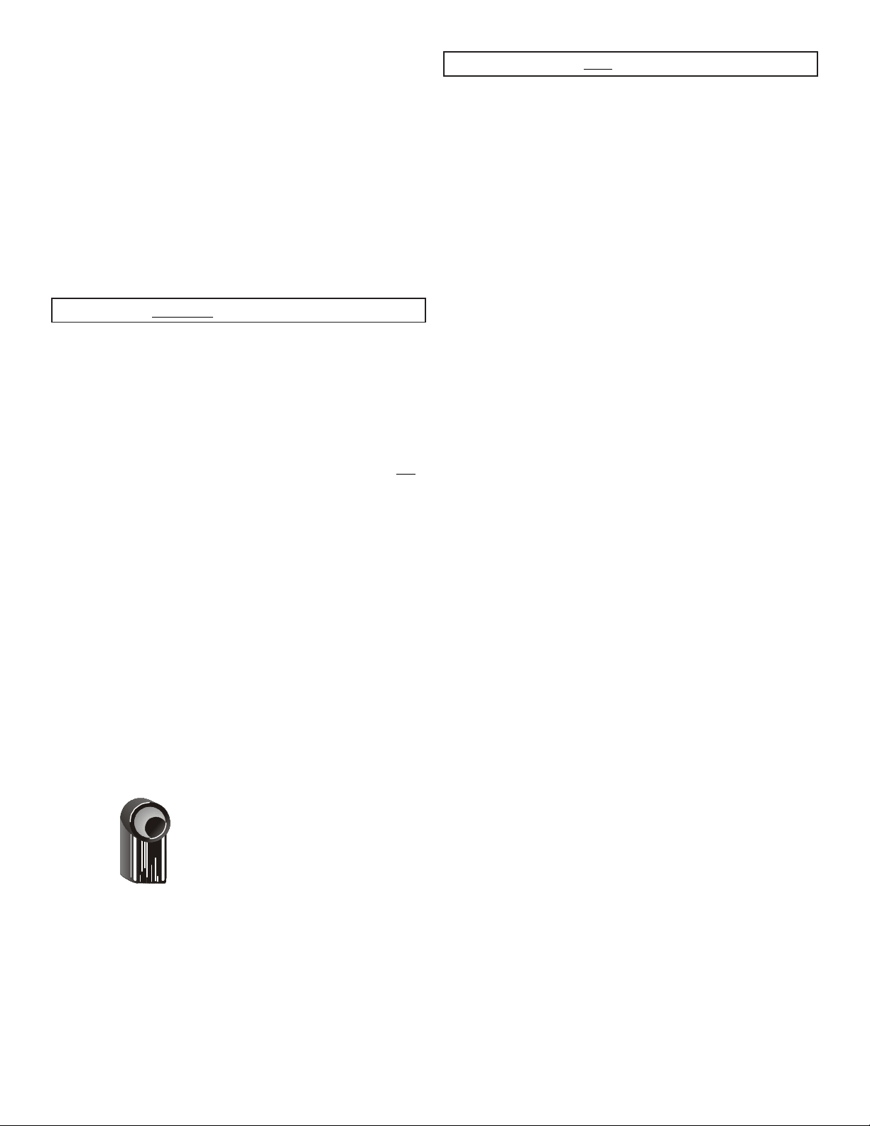
WATER SUPPLY REQUIREMENTS
Hot and cold water faucets MUST be installed within 42 inches
(106.68 cm) of your laundry center’s water inlet. The faucets
MUST be 3/4 inch (1.9 cm) garden hose type so inlet hoses can
be connected. Water pressure MUST be between 10 and 120
pounds per square inch (maximum unbalance pressure, hot vs.
cold, 10 psi). Your water department can advise you of your
water pressure.
NEMA 10-30R
Page 4
Do not allow combustible materials (for
example: clothing, draperies/curtains, paper) to come in
contact with exhaust system. The dryer MUST NOT be
exhausted into a chimney, a wall, a ceiling, or any concealed
space of a building which can accumulate lint, resulting in a fire
hazard.
Exceeding the length of duct pipe or number
of elbows allowed in the "MAXIMUM LENGTH" charts can
cause an accumulation of lint in the exhaust system. Plugging
the system could create a fire hazard, as well as increase drying
times.
Do not screen the exhaust ends of the vent
system, nor use any screws, rivets or other fastening means
that extend into the duct and catch lint to assemble the
exhaust system. Lint can become caught in the screen, on the
screws or rivets, clogging the duct work and creating a fire hazard
as well as increasing drying times. Use an approved vent hood
to terminate the duct outdoors, and seal all joints with duct
tape. All male duct pipe fittings MUST be installed downstream
with the flow of air.
Explosion hazard. Do not install the dryer
where gasoline or other flammables are kept or stored. If
the dryer is installed in a garage, it must be a minimum of 18
inches (45.7 cm) above the floor. Failure to do so can result in
death, explosion, fire or burns. The exhaust system back pressure
MUST not exceed 0.6 inches (1.52 cm) of water column,
measured with an inclined manometer at the point the exhaust
connects to the dryer. The exhaust system should be inspected
and cleaned a minimum of every 18 months with normal
usage. The more the dryer is used, the more often you should
check the exhaust system and vent hood for proper operation.
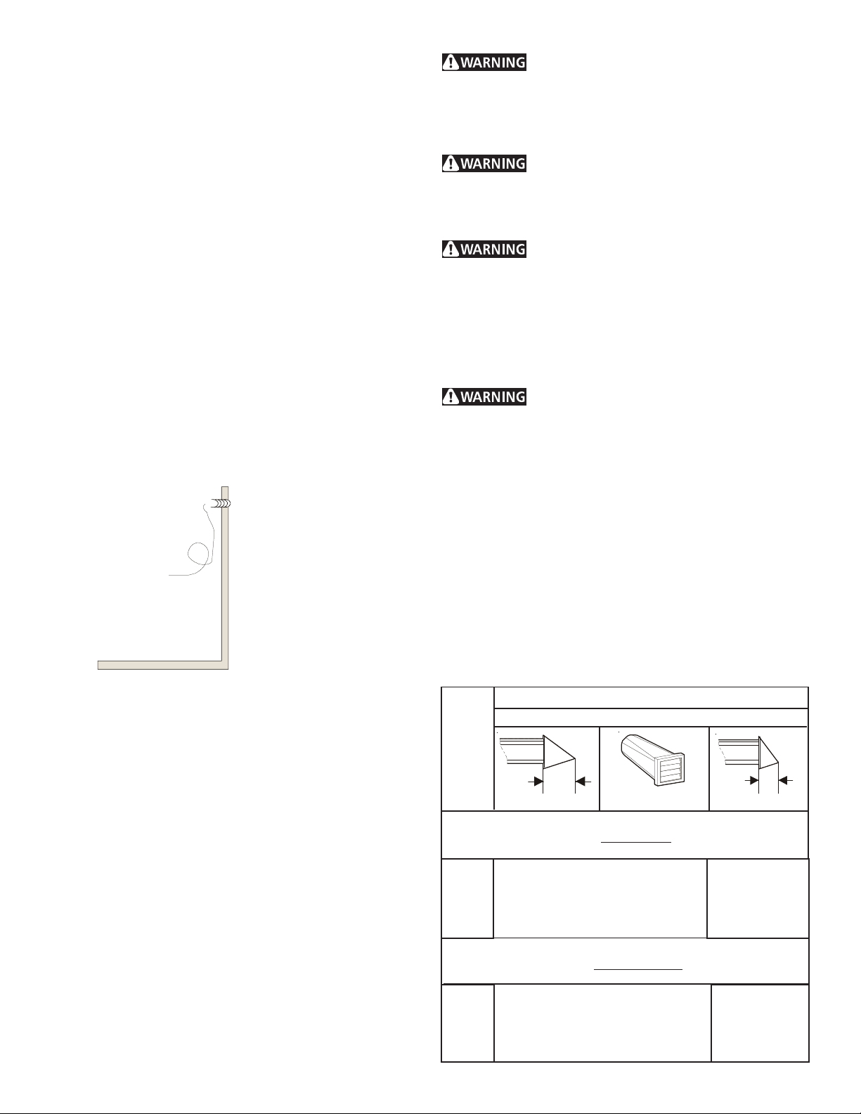
The maximum length of the exhaust system depends upon the
type of duct used, number of elbows and type of exhaust hood.
The maximum length for both rigid and flexible duct is shown in
the chart below.
EXHAUST DUCT LENGTHS
EXHAUST HOOD TYPE
Number
of 90°
Turns
4”
(10.2 CM)
MAXIMUM LENGTH OF 4-INCH (10.2 CM)
DIAMETER RIGID METAL DUCT
0
1
2
3
MAXIMUM LENGTH OF 4-INCH (10.2 CM)
0
1
2
3
56 ft. (17.07 m)
46 ft. (14.02 m)
34 ft. (10.36 m)
32 ft. (9.75 m)
DIAMETER FLEXIBLE METAL DUCT
30 ft. (9.14 m)
22 ft. (6.7 m)
16 ft. (4.88 m)
10 ft. (3.05 m)
Louvered
42 ft. (12.8 m)
36 ft. (10.97 m)
28 ft. (8.53 m)
18 ft. (5.48 m)
22 ft. (6.7 m)
14 ft. (4.27 m)
10 ft. (3.05 m)
5 ft. (1.5 m)
2.5”
(6.35 CM)
4
Page 5
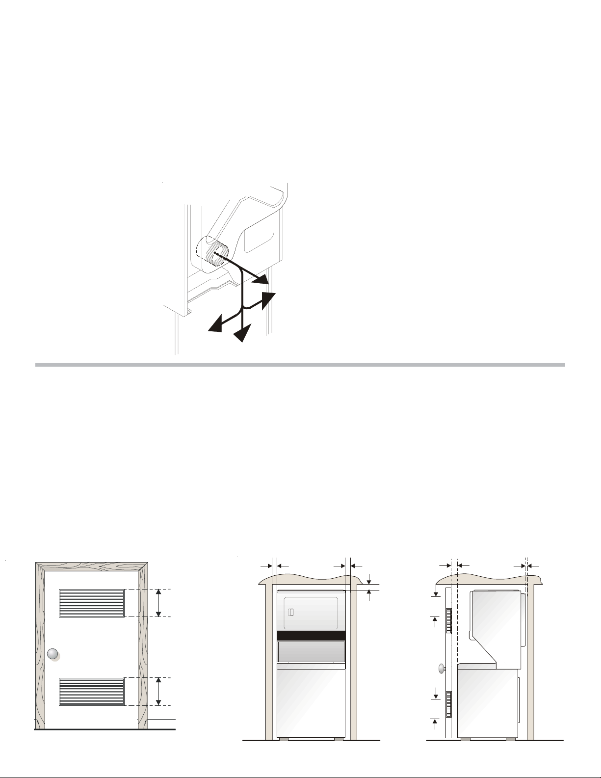
The laundry center may be exhausted four (4) ways with rear
flush installation:
1. Straight back
2. Down (8 inch [20.32 cm] length of 4 inch [10.16 cm] rigid
duct and 1 elbow down)
3. Left (8 inch [20.32 cm] length of 4 inch [10.16 cm] rigid
duct, 1 elbow down and 1 elbow left)
4. Right (8 inch [20.32 cm] length of 4 inch [10.16 cm] rigid
duct, 1 elbow down and 1 elbow right)
To exhaust up, add an 11 inch (27.94 cm) length of standard 4
inch (10.16 cm) diameter duct and a 90° elbow. The unit will
be positioned about 4½ inches (11.43 cm) away from the wall
(flush to wall exhausting may be done by going below the dryer
then sideways).
An exhaust hood positioned
to line up with the dryer
exhaust can be installed
directly through the outside
wall. To exhaust to the side
or down, add an 8 inch
(20.32 cm) length of standard
4 inch (10.16 cm) diameter
duct and a 90° elbow.
GAS SUPPLY REQUIREMENTS
1.Installation MUST conform with local codes, or in the absence
of local codes, with the National Fuel Gas Code, ANSI Z223.1
(latest edition) or in Canada, the current AN/CGA B149.
2.The gas supply line should be of 1/2 inch (1.27 cm) pipe.
3.If codes allow, flexible metal tubing may be used to connect
your dryer to the gas supply line. The tubing MUST be
constructed of stainless steel or plastic-coated brass.
4.The gas supply line MUST have an individual shutoff valve.
5.A 1/8 inch (0.32 cm) N. P. T. plugged tapping, accessible for
test gage connection, MUST be installed immediately
upstream of the gas supply connection to the dryer.
6.The dryer and its individual shutoff valve MUST be
disconnected from the gas supply piping system during any
pressure testing of the gas supply piping system at test
pressures equal to or less than 1/2 psig (3.45 kPa).
7.The dryer MUST be isolated from the gas supply piping system
by closing its individual manual shutoff valve during any
pressure testing of the gas supply piping system at test pressures
equal to or less than 1/2 psig (3.45 kPa).
LOCATION OF YOUR LAUNDRY CENTER
DO NOT INSTALL YOUR LAUNDRY CENTER:
1.In an area exposed to dripping water or outside weather conditions.
2.In an area where it will come in contact with curtains or drapes.
3.On carpet. Floor MUST be solid with a maximum slope of 1 inch (2.54 cm).
INSTALLATION IN RECESS OR CLOSET
1.A laundry center installed in a bedroom, bathroom, recess or closet, MUST be exhausted outdoors.
2.No other fuel burning appliance shall be installed in the same closet as the Gas laundry center.
3.Your laundry center needs the spacearound it for proper ventilation.
DO NOT INSTALL YOUR LAUNDRY CENTER IN A CLOSET WITH A SOLID DOOR.
4.A minimum of 120 square inches (774.2 square cm) of opening, equally divided at the top and bottom of the door, is required.
Air openings are required to be unobstructed when a door is installed. A louvered door with equivalent air openings for the full
length of the door is acceptable.
5.The following illustrations show minimum clearance dimensions and air openings for proper operation in a recess or closet
installation.
60 SQ. IN.
(387.1 SQ. CM)
0 IN.
(0 C M)
0 IN.
(0 C M)
DRYER
1 IN.
(2.54 CM)
60 SQ. IN.
(387.1 SQ. CM)
0 IN.
(0 C M)
Closet Door
60 SQ. IN.
(387.1 SQ. CM)
WASHER
60 SQ. IN.
(387.1 SQ. CM)
5
Page 6
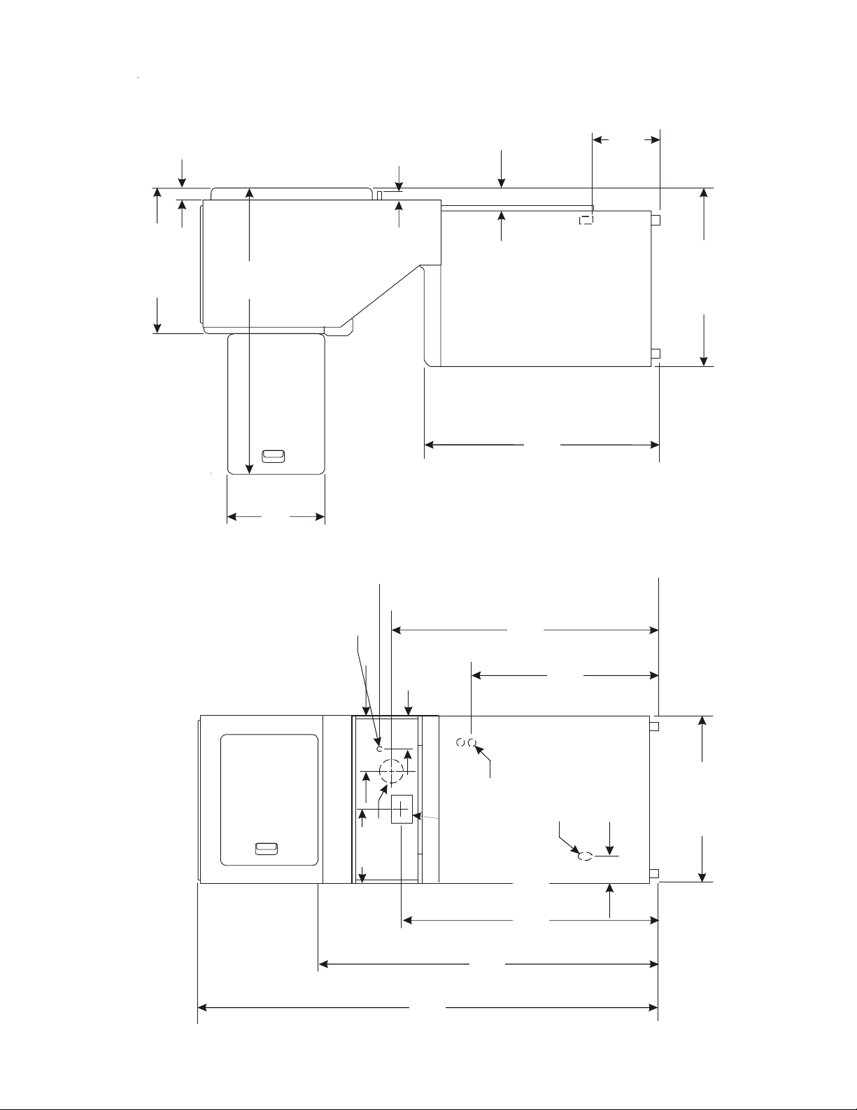
2 ½ IN.
(6.35 CM)
1 7/8 IN.
(4.76 CM)
4 13/16 IN.
(12.22 CM)
11 7/16 IN.
(29.5 CM)
25 ¼ IN.
(64.13 CM)
47“
16 ¼ IN.
(41.27 CM)
ROUGH-IN DIMENSIONS
(78.26 CM)
30 13/16 IN.
36 1/16IN.
(91.60 CM)
43 IN.
PIPE (REAR)
GAS SUPPLY
5 ¼ IN.
(13.33 CM)
(109.22 CM)
41 ¼ IN
(104.77 CM)
29 7/16 IN
(74.77 CM)
9 3/8 IN.
(23.81 CM)
(REAR)
DRAIN OUTLET
VENT
12 ½ IN.
(31.7 5 CM)
ELECTRICAL
CONNECTION
75 ½ IN.
(191.77 CM)
54 5/16 IN.
(REAR)
WATER INLETS
43 IN.
(109.22 CM)
(137.95 CM)
3 ¾ IN.
(9.52 CM)
27 IN.
(68.58CM)
Page 7

PLASTIC SPACER
BLOC K
MECHANISM
SHIPPING
BOLT
FOAM
SHIPPING
PA D
POWER CORD
(IF EQUIPPED)
DRAIN HOSE
Page 8

ELECTRICAL INSTALLATION
GROUNDING REQUIREMENTS
ALL ELECTRIC Laundry Centers
WARNING
The following are specific requirements for
proper and safe electrical installation of your laundry center.
Failure to follow these instructions can create electrical shock
and/or a fire hazard.
WARNING
Electrical shock can result if the laundry center is not properly
grounded. Follow the instructions in this manual for proper
grounding.
WARNING
laundry center. Some extension cords are not designed to
withstand the amounts of electrical current this laundry center
utilizes and can melt, creating electrical shock and/or fire hazard.
Locate the laundry center within reach of the receptacle for the
length power cord to be purchased, allowing some slack in the
cord. Refer to the pre-installation requirements in this manual
for the proper power cord to be purchased.
WARNING
installed onto power cord. If the strain relief is not attached, the
cord can be pulled out of the laundry center and can be cut by
any movement of the cord, resulting in electrical shock.
This appliance MUST be properly grounded.
Do not use an extension cord with this
A U.L. approved strain relief must be
Non-Canadian ELECTRIC Laundry Center
DANGER
grounding conductor can result in a risk of electrical shock.
Check with a licensed electrician if you are in doubt as to whether
the appliance is properly grounded.
For a grounded, cord-connected laundry center:
1. The laundry center MUST be grounded. In the event of
malfunction or breakdown, grounding will reduce the risk of
electrical shock by a path of least resistance for electrical
current.
2. If your laundry center is equipped with a power supply cord
having an equipment-grounding conductor and a grounding
plug, the plug MUST be plugged into an appropriate, copper
wired receptacle that is properly installed and grounded in
accordance with all local codes and ordinances. If in doubt,
call a licensed electrician. Do not modify plug provided
with the appliance.
For a permanently connected laundry center:
The laundry center MUST be connected to a grounded metal,
permanent wiring system; or an equipment grounding conductor
MUST be run with the circuit conductors and connected to the
equipment-grounding terminal or lead on the appliance.
Improper connection of the equipment
Canadian ELECTRIC Laundry Center
WARNING
Do not use an aluminum wired receptacle
with a copper Wired power cord and plug (or vice versa). A
chemical reaction occurs between copper and aluminum and
can cause electrical shorts.
The proper wiring and receptacle is a copper wired power
cord with a copper wired receptacle OR aluminum wired
power cord with an aluminum wired receptacle.
NOTE: Laundry centers operating on a 208 volt power supply
will have longer drying times than laundry centers operating on
a 240 volt power supply.
DANGER
grounding conductor can result in a risk of electrical shock.
Check with a licensed electrician if you are in doubt as to
whether the appliance is properly grounded.
For a grounded cord connected laundry center:
1. The laundry center MUST be grounded. In the event of
malfunction or breakdown, grounding will reduce the risk of
electrical shock by providing a path of least resistance for
the electrical current.
2. Since your laundry center is equipped with a power supply
cord having an equipment-grounding conductor and a
grounding plug, the plug MUST be plugged into an
appropriate outlet that is properly installed and grounded in
accordance with all codes and ordinances. If in doubt, call a
licensed electrician.
Improper connection of the equipment
ALL GAS Laundry Centers
1. The laundry center is equipped with a three-prong (grounding)
plug for your protection against shock hazard and should
be plugged directly into a properly grounded three-prong
receptacle. Do not cut or remove the grounding prong from
the plug.
8
Page 9

ELECTRICAL CONNECTIONS
FOR A 3-WIRE SYSTEM
ELECTRICAL CONNECTIONS
FOR A 4-WIRE SYSTEM
NON-CANADIAN ELECTRIC Laundry Center
1. Remove the screw securing the
terminal block access cover to
the rear panel and remove cover.
2. Install a U.L. approved strain
relief connector in the entry
hole on the back panel.
3. Insert a NEMA 10-30 Type SRDT,
U.L. approved power cord through the strain relief.
4. Attach the power cord neutral (central wire) conductor to
the silver colored center terminal on the terminal block.
Tighten the screw securely.
GREEN GROUND SCREW
NEUTRAL
GROUND
WIRE
SILVER TERMINAL
NON-CANADIAN ELECTRIC Laundry Center
1. Remove the screw securing the
terminal block access cover to the
rear panel and remove cover.
2. Install a U.L. approved strain relief
connector in the entry hole on the
back panel.
3. Remove the neutral ground wire from the green ground
screw located above the termial block.
NEUTRAL
GROUND
WIRE
5. Attach the remaining two power cord outer conductors to
the outer brass colored terminals on the terminal block.
Tighten both screws securely.
6. Tighten the screws securing the cord restraint against the
power cord.
7. Reinstall the terminal access cover.
4. Insert a NEMA 14-30 Type ST or SRDT, U.L. approved power
cord through the strain relief.
5. Attach the green power cord ground wire to the cabinet
with the green ground screw.
6. Attach the white (neutral) wire from the power cord and the
neutral ground wire from the appliance harness to the silver
colored center terminal on the terminal block. Tighten the
screw securely.
7. Attach the red and black wires from the power cord to the
outer brass-colored terminals on the terminal block. Tighten
both screws securely.
8. Tighten the screws securing the cord restraint firmly against
the power cord.
9. Reinstall the terminal block access cover.
Page 10

9. Remove the two (2) screws securing the dryer front access
panel to the dryer cabinet. Lift the panel until the tabs can
be disengaged from the cabinet. Remove the panel and set
aside.
Access
Panel
Screws
Page 11

REPLACEMENT PARTS
10. Connect the exhaust duct to outside duct work. Use duct
tape to seal all joints.
11. Plug the power cord into a grounded outlet.
NOTE: Check to ensure the power is off at a circuit breaker/
fuse box before plugging the power cord into an
outlet.
12. Turn on the power at a circuit breaker/fuse box.
Before operating the dryer, make
sure the dryer area is clear and free from
combustible materials, gasoline, and other
flammable vapors. Also see that nothing (such as
boxes, clothing, etc.) obstructs the flow of
combustion and ventilation air.
13. Reinstall the dryer front access panel.
14. Run the washer and dryer though a cycle. Check for proper
operation.
NOTE: On gas dryers, before the burner will light, it is
necessary for the gas line to be bled of air. If the burner
does not light within 45 seconds the first time the
dryer is turned on, the safety switch will shut the
burner off. If this happens, turn the timer to “OFF”
and wait 5 minutes before making another attempt to
light.
If replacement parts are needed for your laundry center, contact
the source where you purchased your laundry center.
WARNING
band after the laundry center is unpacked. Children might use
them for play. Cartons covered with rugs, bedspreads, or plastic
sheets can become airtight chambers causing suffocation. Place
all materials in a garbage container or make materials inaccessible
to children.
servicing controls. Wiring errors can cause improper and
dangerous operation. Verify proper operation after servicing.
WARNING
literature included with this laundry center are not meant to
cover every possible condition and situation that may occur. Good
safe practice and caution MUST be applied when installing,
operating and maintaining any appliance.
Maximum benefits and enjoyment are achieved when
all the Safety and Operating instructions are understood
and practiced as a routine with your laundry tasks.
Destroy the carton, plastic bags, and metal
Label all wires prior to disconnection when
The instructions in this manual and all other
15. If your laundry center does not operate, please review the
“Avoid Service Checklist” located in your Owner’s Guide
before calling for service.
16. Place these instructions in a location near the laundry
center for future reference.
NOTE: A wiring diagram is located behind the dryer front
access panel.
10
Page 12

Table des matières
SUJET PAGE
Avantl’installation................................................................................................................................................13
Exigences électriques.............................................................................................................................................13
Exigences d'alimentation.......................................................................................................................................13
Exigenses de vidange.............................................................................................................................................13
Exigenses du circuit d'evacuation......................................................................................................................14-15
Exigenses d'alimentation en gas..........................................................................................................................15
Emplacement du combiné laveuse/sécheus........................................................................................................15
Dimensions de l’emplacement...............................................................................................................................16
Installation dans une maison mobile....................................................................................................................17
Déballage.................................................................................................................................................................17
Installation électrique...........................................................................................................................................18
Exigences de mise à la terre...................................................................................................................................18
Connexions électrique s - 3 fils et 4 fils.............................................................................................................18-19
Installation..........................................................................................................................................................19-20
Pièces de rechange................................................................................................................................................20
Sécuritaire de la Laveuse / Sécheuse
Avant de commencer, lire attentivement le présent document. Cela simplifiera l’installation et assurera la pose
correcte et sécuritaire de la sécheuse. Après l’installation, laisser ce document à proximité de la sécheuse pour
référence future.
REMARQUE : L’alimentation électrique de la sécheuse doit respecter les codes et ordonnances locaux ainsi
que l’édition la plus récente du Code ANSI/NFPA 70, ou au Canada, le Code canadien d'électricité, ACNOR
C22.1, partie1.
REMARQUE : L’alimentation en gaz de la sécheuse doit respecter les codes et ordonnances locaux ainsi que
l’édition la plus récente du Code ANSI Z223.1, ou au Canada, le code CAN/ACG B149.12.
REMARQUE : La sécheuse est conçue conformément au code ANSI Z 21.5.1 ou ANSI/UL 2158 - CAN/ACG
C22.2 No. 112 (l’édition la plus récente) pour un USAGE DOMESTIQUE seulement. Cette sécheuse n'est pas
recommandée pour utilisation commerciale, comme par exemple un restaurant ou un salon de coiffure, etc.
Pour votre sécurité, suivre les directives données dans le présent guide afin de minimiser
les risques d’incendie, d’explosion, de dommages matériels, de blessures et de mort.
- Ne pas entreposer ni utiliser d’essence ou d’autres vapeurs ou liquides inflammables à proximité de
cette sécheuse ou de tout autre appareil électroménager.
- QUE FAIRE S’IL Y A UNE ODEUR DE GAZ
· N’allumer aucun appareil électrique.
· Ne toucher aucun commutateur électrique; ne pas utiliser le téléphone dans l’immeuble.
· Faire sortir tous les occupants de la pièce, de l’immeuble ou de la zone avoisinante.
· Appeler la compagnie de gaz immédiate-ment en utilisant le téléphone d’un voisin. Suivre les
instructions de la compagnie de gaz.
· S’il est impossible de joindre la compagnie de gaz, appeler les pompiers.
L’installation et les réparations doivent être effectuées par un technicien qualifié, un agent de service ou
la compagnie de gaz.
12
Page 13

AVANT L’INSTALLATION
Outils et matériel requis pour l’installation :
1. Tournevis à pointe cruciforme
2. Pinces multiprise
3. Niveau de menuisier
4. Tournevis à pointe plate ou à lame droite
5. Ruban adhésif pour conduites
6. Conduite en métal rigide ou flexible de 10,2 cm (4 po)
7. Grille de sortie
8. Pâte à joint pour conduites (modèle à gaz)
9. Couteau à mastic en plastique
CORDON D’ALIMENTATION - Le combiné laveuse/ sécheuse á
gaz est d’un cordon d’alimentation électrique à 3 fils de 120 volts.
NOTE: Do not under
REMARQUE : Il ne faut
any circumstances
en aucun cas retirer la
broche de mise à la
remove grounding
terre de la fiche.
prong from plug.
INSTALLATION ÉLECTRIQUE
Sécheuses ÉLECTRIQUES
CIRCUIT - Dérivation distincte de 30 A avec fusibles à retardement
ou disjoncteurs d’au moins 30 A.
ALIMENTATION ÉLECTRIQUE - 3 fils, 240 volts, une phase,
60 Hz, courant alternatif. (Canada - 240 volts, une phase, 60 Hz,
courant alternatif.)
CORDON D’ALIMENTATION ÉLECTRIQUE - La sécheuse DOIT
être reliée à un cordon d’alimentation électrique à 3 conducteurs
NEMA 10-30 de type SRDT d’une capacité minimale de 240 volts,
courant alternatif, 30 A, avec fiche en L à 3 broches pleines ou
repliées conçue pour le branchement d’une sécheuse. Si étant
installé dans une nouvelle installation de circuit de branche,
manufacturée (mobile) à la maison, véhicule la récréationnel
ou secteur qui interdisent fondre par le conducteur neutre, elle
DOIT être reliée à un cordon d’alimentation électrique à
4 conducteurs NEMA 14-30 de type SRDT ou ST (au besoin) d’une
capacité minimale de 240 volts, courant alternatif, 30 A, avec
fiche en L à 4 broches pleines ou repliées conçue pour le
branchement d’une sécheuse. Se reporter à la section
BRANCHEMENT ÉLECTRIQUE D’UNE INSTALLATION À 4 FILS.
(Canada - Cordon d'alimentation à 4 fils branché à la sécheuse.)
BROCHE DE MISE
Grounding Prong
À LA TERRE
EXIGENCES D'ALIMENTATION EN EAU
Les robinets d'eau chaude et d'eau chaude et d'eau froide
DOIVENT êntre installés à moins de 42 pounces ( 106,68 cm )
de
l'arrivée d'eau du combiné. Les robinets DOIVENT tre du type
pour boyau de jardin de 3/4 pounce (1,9 cm), de manière à
pouvoir raccader les boyaux d'arrivée d'eau. La pression d'eau
DOIT se siteur entre 10 et 120 livres par pounce carré ( déséquilibre de pression maximale, eau chaude vs eau froide, 10
psi ). Le service d'aqueduc peut vous informer sur la pression
d'eau.
EXIGENCES DE VIDANGE
1. Le circit de vidange doit permettre d'évacuer 17 gallons à la
minute.
2. Le diamétre du tuyau de vidange doit être d'un minimum
de 1 - 1/4 po (3,18 cm).
3. La hauteur hors sol du tuyau de vidange doit être :
Minimale: 33 po (83,82 cm)
Maximale: 96 po (244 cm)
PRISE - Prise NEMA 10-30R située de façon à ce que le cordon
d’alimentation électrique soit accessible une fois la sécheuse en
place. (Canada - prise NEMA de 14-30R.)
NEMA 10-30R
Combiné laveuse /sécheuse à GAZ
NEMA 14-30R
CIRCUIT - Dérivation distincte de 15 A minimum avec fusible à
retardement ou disjoncteur.
ALIMENTATION ÉLECTRIQUE - 3 fils, 120 volts, une phase, 60
Hz, courant alternatif.
96 po Max.
(244 cm)
33 po Min.
(83.82cm)
NOTA: Si l'installation nécessite un tuyau de vidange plus
long, demandez à un technicien qualifié d'installer un
boyau de vindage plus long, P/N 131461201,
disponsible chez un distributeur autorisé de pièces.
Pour les circuits de vidange au sol, installez un ensemble
de siphon, se procurer auprès d'une quincaillerie locale.
13
Page 14

ÉVACUATION DE L’AIR
Utiliser uniquement une conduite en métal rigide ou flexible de
10,2 cm (4 po) de diamètre (minimum) ainsi qu’une grille de sortie
approuvée pourvue de clapets qui s’ouvrent lorsque la sécheuse
fonctionne. Quand la sécheuse s’arrête, les clapets se ferment
automatiquement pour éviter les courants d’air et l’entrée
d’insectes ou de rongeurs. Afin de ne pas obstruer l’évacuation de
l’air, laisser une distance minimum de 30,5 cm (12 po) entre la
grille de sortie et le sol ou tout autre obstacle.
Les mises en garde qui suivent se
rapportent directement au fonctionnement correct et
sécuritaire de la sécheuse. Toute dérogation à ces mises en
garde pourrait ralentir le séchage et entraîner des risques
d’incendie.
N’installez pas la Sécheuse avec des matériels de
ventilation en matières plastiques flexibles.
Si la conduite existante est en plastique ou en papier métallique,
la remplacer par une conduite en métal rigide ou flexible. Au
Canada et aux Etats-Unis si le conduit est de métal (type feuille
d’aluminium), celui-ci doit être d’un type spécifique identifié par
le fabricant, recommandé pour l’utilisation avec des Sécheuses ;
et aux Etats-Unis il doit en outre remplir la norme UL 215Å. Les
matériaux de ventilation flexibles peuvent s’abimer facilement et
recueillir du duvet. Ces conditions obstrueront la circulation d’air
de la Sécheuse de vêtements et augmenteront le risque
d’incendie. S’assurer qu’il n’y a pas de charpie dans la
conduite existante avant d’installer la conduite de la
sécheuse.
La sécheuse doit être connectée à une bouche d’évacuation
vers l’extérieur du bâtiment ou de l’immeuble. Vous devez
inspecter régulièrement l’évent extérieur et enlever toute
accumulation de charpie autour de l’évent et dans la cavité du
conduit d’évacuation.
Ne laisser aucun matériau inflammable (comme des
vêtements, des tentures, des rideaux ou du papier) entrer en
contact avec les conduits d’évacuation.
Augmenter la longueur du conduit rigide ou le nombre de
coudes permis au tableau «LONGUEUR MAXIMUM» risque de
réduire la capacité d'évacuation du circuit. Obturer le circuit peut
créer un risque d'incendie et augmenter le temps de séchage.
N’obstruez pas les extrémités du tube de ventilation, ni utilisez
des vis, rivets ou autres moyens de fixation qui peuvent obstruer
le conduit et recueillir du duvet. L’engorgement subséquent
risquerait de ralentir le temps de séchage, voire de causer un
incendie. Installer une bouche d’évacuation approuvée à l’extérieur
et sceller tous les joints à l’aide d’un ruban adhésif à conduits.
Tous les raccords de conduit mâles
le sens de la circulation d’air.
Risques d'explosion. Ne pas installer la
sécheuse à un endroit où l'on garde de la gazoline ou tout autre
produit inflammable. Si la sécheuse est installée dans un garage,
elle doit être à un minimum de 45,7 cm (18 po) au-dessus du
plancher. Toute dérogation pourrait provoquer la mort, l'explosion,
l'encendie ou les brûlures.
1. La contre-pression du circuit d'evacuation ne DOIT pas
excéder 0.6 ponces (1,52 cm) de colonne d'eau, mesuréeavec
un manométre à tube incliné au point ou le conduit
d'évacuation est connecté sécheuse.
2. Il faut vérifier et nettoyer le circuit d'évacuation au moins
tous les deux ans dans des conditions d'utilisation normale.
Plus la sécheuse est utilisée fréquemment, plus le circuit
et le registre d'évacuation doivent être vérifies pour assurer
un bon.
La longueur maximum du systém d'évacuation dépend du type
de conduit utilisé, du nombre de coudes et du type de registre
d'évacuation. La longueur maximum de conduits rigides et
flexibles est indiquée dans le tableau suivant:
DOIVENT
être installés dans
– Risque d’incendie – une Sécheuse de vêtement doit être
aéré à l’air libre. N’aérez pas la Sécheuse dans une cheminée,
une paroi, un plafond, un espace fermé ou aucun espace caché
du bâtiment. Une sécheuse à linge produit de la charpie
combustible. Si l’air n’était pas repoussé à l’extérieur de la maison,
de petites particules de charpie se retrouveraient dans la pièce où
est installée la sécheuse. Toute accumulation de charpie dans la
maison peut présenter des risques pour la santé et des risques
d’incendie.
14
Page 15

EMPLACEMENT DU COMBINÉE LAVEUSE/SÉCHEUSE
NE PAS INSTALLER COMBINÉ LAVEUSE/ SÉCHEUSE :
1. Dans un endroit exposé à un écoulement d’eau ou aux
conditions atmosphériques.
2. Dans un endroit où elle serait en contact avec des rideaux,
draperies ou tout ce qui obstruera le flux d'air de combustion
et de ventilation.
3. Sur un tapis. Le plancher DOIT être ferme et présenter une
pente de 2,54 cm (1 po) au maximum.
INSTALLATION DANS UNE ALCÔVE OU UN PLACARD
1. Toute sécheuse installée dans une chambre à coucher, une
salle de bain, une alcôve ou un placard DOIT être reliée à une
conduite d’évacuation d’air se terminant à l’extérieur de la
maison.
2. Aucun autre appareil brûlant du combustible ne doit être
installé dans le même placard que la sécheuse au Gaz.
3. La sécheuse a besoin d’un dégagement suffisant pour
permettre la circulation de l’air.
NE PAS INSTALLER LA SÉCHEUSE DANS UN PLACARD
POURVU D’UNEPORTE PLEINE.
4. Une ouverture minimum de 774,2 cm² (120 po²) répartie
également entre le haut et le bas de la porte est requise. Cette
ouverture ne doit pas être obstruée lorsque la porte est en place.
Une porte à volets dont les ouvertures totalisent la norme décrite
ci-dessus est acceptable.
5. Les illustrations qui suivent indiquent la dimension minimum
de dégagement pour un fonctionnement adéquat dans une
niche ou une armoire.
ALIMENTATION EN GAZ
Remplacer le tuyau de raccordement en
cuivre non recouvert de plastique. Il FAUT utiliser du laiton
inoxydable ou recouvert de plastique.
1. L’installation DOIT respecter les codes locaux, ou s’il n’existe
pas de codes locaux, le code ANSI Z223.1 (l’édition la plus
récente) ou au Canada, le Code actuel CAN/CGA B149.
2. La conduite d’alimentation en gaz doit mesurer 1,27 cm (1/
2 po).
3. Si les codes le permettent, un tuyau en métal flexible peut être
utilisé pour connecter la sécheuse à l’alimentation en gaz. Le
tuyau DOIT être fabriqué en acier inoxydable ou en cuivre avec
un revêtement de plastique.
4. La conduite d’alimentation en gaz DOIT comporter un robinet
d’arrêt distinct.
5. Une prise de 0,32 cm (1/8 po) NPT accessible pour le
branchement d’un manomètre DOIT être installée tout juste
en amont du branchement de la conduite d’alimentation en
gaz sur la sécheuse.
6. La sécheuse DOIT être débranchée de la canalisation de gaz
pendant toute vérification de pression de l’alimentation en gaz
à des pressions qui dépassent 3,45 kPa (1/2 lb/po²).
7. La sécheuse DOIT être isolée de la canalisation de gaz pendant
toute vérification de pression de l’alimentation en gaz à des
pressions égales ou inférieures à 3,45 kPa (1/2 lb/po²).
15
Page 16

2 ½ IN.
(6.35 CM)
1 7/8 IN.
(4.76 CM)
4 13/16 IN.
(12.22 CM)
11 7/16 IN.
(29.5 CM)
25 ¼ IN.
(64.13 CM)
47“
(78.26 CM)
30 13/16 IN.
36 1/16IN.
(91.60 CM)
16 ¼ IN.
(41.27 CM)
(ARRIÉRE)
43 IN.
TUYAU D'ALIMENTATION EN GAZ
PIPE (REAR)
GAS SUPPLY
(109.22 CM)
41 ¼ IN
(104.77 CM)
5 ¼ IN.
(13.33 CM)
29 7/16 IN
(74.77 CM)
Dimensions de l’emplacement
9 3/8 IN.
(23.81 CM)
12 ½ IN.
(31.75 CM)
VENT
CONNEXCIONS ÉLECTRIQUES
ELECTRICAL
75 ½ IN.
(191.77 CM)
WATER INLETS
CONNECTION
ARRIVÉES D'EAU (ARRIÉRE)
54 5/16 IN.
(137.95 CM)
16
(REAR)
DRAIN OUTLET
VIDANGE (ARRIÉRE)
3 ¾ IN.
(9.52 CM)
27 IN.
(68.58CM)
(REAR)
43 IN.
(109.22 CM)
Page 17

17
Page 18

INSTALLATION ÉLECTRIQUE
TOUS combinées laveude/sécheuses ÉLECTRIQUES
Les mises en garde qui suivent se
rapportent directement au branchement électrique correct
et sécuritaire de la sécheuse. Toute dérogation à ces mises
en garde pourrait entraîner des risques choc électrique et
d’incendie.
Pour brancher la sécheuse en permanence :
La combiné DOIT être branchée à une installation métallique
mise à la terre en permanence; sinon, un conducteur de mise
à la terre de l’appareil doit suivre les conducteurs du circuit et
être branché à la borne ou à la connexion de mise à la terre
de l’appareil.
Combiné laveuse/sécheuses ÉLECTRIQUES Canadiennes
Cet appareil DOIT être convenablement mis à la terre. Si le
combiné présenterait des risques choc électrique si elle n’était
pas convenablement mise à la terre. Respecter les directives de
mise à la terre contenues dans cette notice pour une mise à la
terre correcte.
Ne pas utiliser de cordon de rallonge avec ce combiné.
Certains cordons de rallonge ne sont pas conçus pour supporter
l’intensité du courant qu’utilise cette combiné; ils peuvent fondre
et présenter un risque choc électrique ou d’incendie. Placer la
sécheuse à portée de la prise murale afin de déterminer la
longueur du cordon à acheter et prévoir un certain jeu dans la
longueur du cordon. Se reporter à la section «Avant l’installation»
de cette notice pour savoir quel type de cordon acheter.
Un détendeur approuvé par U.L. doit être fixé au cordon
d’alimentation. Si le détendeur n’était pas présent, le cordon
pourrait être arraché de la combiné ou coupé par tout type de
mouvement, ce qui présenterait un risque choc électrique.
Ne pas utiliser une prise à conducteurs en aluminium avec
un cordon ou une prise à conducteurs en cuivre (ni l’inverse). Une
réaction chimique se produit entre le cuivre et l’aluminium qui
pourrait causer un court-circuit. Il faut utiliser un cordon
d’alimentation à conducteurs en cuivre avec une prise à
conducteurs en cuivre.
REMARQUE : Le délai séchage d'un combiné laveuse/
sécheuse qui fonctionnent avec une alimentation de 208
volts auront un temps de séchage plus long que celles qui
utilisent une alimentation de 240 volts.
MISE À LA TERRE
DANGER
mise à la terre pourrait présenter un risque choc électrique. En
cas de doute quant à la mise à la terre adéquate de l’appareil,
contacter un électricien agréé.
Pour brancher et mettre à la terre la sécheuse à l’aide d’un cordon
d’alimentation :
1. La sécheuse doit être mise à la terre. En cas de mauvais
fonctionnement ou de panne, la mise à la terre réduit les
risques choc électrique en offrant un parcours de moindre
résistance au courant.
2. Puisque la sécheuse est pourvue d’un cordon d’alimentation
électrique comportant un conducteur et une fiche de terre, la
fiche doit être branchée dans une prise murale à conducteur
en cuivre convenablement raccordée au réseau et mise à la
terre conformément à tous les codes et ordonnances locaux.
En cas de doute, contacter un électricien agréé.
Le branchement inadéquat du conducteur de
TOUS combinés laveuse/ sécheuses à GAZ
Pour votre protection contre les chocs électriques, la sécheuse
est équipée d'une fiche à trois bornes (mise à la terre) et doit être
branchée directement dans une prise à 3 bornes correctement
mise à la terre. Ne pas couper ni enlever la fiche de mise à la
terre de cette prise.
BRANCHEMENT ÉLECTRIQUE D’UNE INSTALLATION À 3 FILS
Non-Canadien
Combiné laveuse/sécheuses ÉLECTRIQUES
Sécheuses ÉLECTRIQUES non-Canadiennes
DANGER
mise à la terre pourrait présenter un risque choc électrique. En
cas de doute quant à la mise à la terre adéquate de l’appareil,
contacter un électricien agréé.
Pour brancher et mettre à la terre la sécheuse à l’aide d’un cordon
d’alimentation :
1. Las combiné DOIT être mise à la terre. En cas de mauvais
fonctionnement ou de panne, la mise à la terre réduit les
risques choc électrique en offrant un parcours de moindre
résistance au courant.
2. Si la combiné est pourvue d’un cordon d’alimentation
électrique comportant un conducteur et une fiche de terre, la
fiche DOIT être branchée dans une prise murale à conducteur
en cuivre convenablement raccordée au réseau et mise à la
terre conformément à tous les codes et ordonnances locaux.
En cas de doute, contacter un électricien agréé. Ne modifiez
pas la prise équipée d’appareil.
Le branchement inadéquat du conducteur de
1. Retirer les vis qui retiennent le couvercle
du panneau de branchement ainsi que le
support de montage du détendeur situés
dans le coin supérieur à l’arrière de la
sécheuse.
2. Poser un détendeur approuvé par U.L. dans le trou du support
où s’insère le cordon d’alimentation. Serrer simplement
l’écrou à la main pour le moment.
3. Enfiler un cordon d’alimentation NEMA 10-30 approuvé par
U.L. de 30 A de type SRDT dans le détendeur.
18
Page 19

4. Fixer le conducteur neutre (conducteur central) du cordon
d’alimentation à la borne centrale argentée du panneau de
branchement. Serrer la vis à fond.
5. Fixer les deux conducteurs restants du cordon d’alimentation
aux bornes cuivrées extérieures du panneau de branchement.
Serrer les deux vis à fond.
6. Serrer à fond les vis qui retiennent le dispositif de retenue du
cordon autour du cordon d’alimentation.
7. Réattacher le couvercle du panneau de branchement.
19
Page 20

10. Reliez les conduits d'évacuation d'air conduit d'évacuation
extétieur. Utilisez un ruban adhésif pour conduits pour
sceller les joints.
11. Brancher le cordon d’alimentation électrique dans une
prise mise à la terre. REMARQUE : S’assurer que le
courant est coupé à la boîte de fusibles ou de disjoncteurs
avant de brancher le cordon d’alimentation dans une
prise.
12. Remettre le courant à la boîte de fusibles ou de disjoncteurs.
Avant d’utiliser la combiné, s’assurer que les
environs de la sécheuse sont exempts de tout matériau
inflammable, d’essence et de toute autre vapeur inflammable.
S’assurer également qu’aucun objet (boîtes, vêtements, etc.)
n’obstrue la circulation de l’air servant à la combustion et à la
ventilation.
13. Faire fonctionner la laveuse/sécheuse sur un cycle complete
pour en vérifier le fonctionnement.
REMARQUE: Dans le cas des laveuse/sécheuses à gaz, la
conduite doit être vidée de son air avant que le brûleur ne
puisse s’allumer. Si le brûleur ne s’allume pas dans les
45 secondes qui suivent le premier démarrage, l’interrupteur
de sûreté éteint automatiquement le brûleur. Si cela se
produit, remettre la minuterie à «OFF» et attendre 5 minutes
avant de tenter une nouvelle fois d’allumer le brûleur.
14 Si la combiné ne fonctionne pas, passer en revue la section
de dépannage inclus dans le Guide de l’utilisateur avant
d’appeler un centre de service.
15. Placer cette notice près de la combiné pour référence future.
REMARQUE: Un schéma de câblage se trouve dans le panneau
de commande ou sous le couvercle de la sécheuse.
PIÈCES DE RECHANGE
Pour obtenir des pièces de rechange pour la laveuse/sécheuse,
contacter le magasin d’où vient la sécheuse .
Lors de tout travail d’entretien ou de
réparation des commandes, étiqueter tous les câbles avant de
les débrancher. Les erreurs de connexion de câble peuvent
entraîner un fonctionnement incorrect et dangereux. Une fois la
réparation ou l’entretien terminé, assurez-vous que l’appareil
fonctionne correctement.
Détruire le carton et les sacs en plastique
après avoir déballé la combiné. Des enfants risqueraient de s’en
servir comme jouet. Les cartons recouverts d’un tapis, d’un
couvre-lit ou d’une feuille de plastique peuvent former une
chambre étanche et faire suffoquer un enfant. Placer le matériel
d’emballage dans une poubelle ou les mettre hors de portée des
enfants.
Les directives qui figurent dans cette notice
et dans les autres documents qui accompagnent la sécheuse ne
sauraient couvrir toutes les circonstances et les situations
possibles. IL FAUT donc faire preuve de jugement et de prudence
pendant l’installation, l’utilisation et l’entretien de tout appareil
électroménager.
20
 Loading...