

Page 1

(7)- (417/FRIGIDAIRE) FRONT LOAD WASHER DOOR
LOCK/SWITCH KIT #131888900.
Page 2
INSTALLATION INSTRUCTIONS
DOOR LOCK/SWITCH KIT - P/N 131888900
This kit replaces the Bitron door lock/switch with a US Controls door lock/switch.
This kit contains the following parts:
(1) Door Lock/Switch
(1) Door Strike
(1) Adapter Harness
(1) Tube Adhesive
(6) Plastic Harness Ties
(1) Installation Instruction
Disconnect the washer from the electrical power
source.
2.
Remove the front service panel.
3.
Open the door, remove the two screws securing the
door strike to the door and remove the strike.
4.
Install the new door strike using the screws removed
in step 3.
Using a razor blade or a sharp putty knife, separate
5.
the bellows from the front panel at the 2, 3, & 4
o’clock positions.
Remove the screws securing the old door
6.
lock/switch to the front panel.
7.
Remove the wires from the old door lock/switch and
remove the switch.
Remove the nine pin plug from the speed control
8.
unit (SCU).
9.
NOTE: If the washer serial number prefix is XC703
and above, go to step 13. If the washer serial number
is below XC703, proceed with instructions 10
through 12.
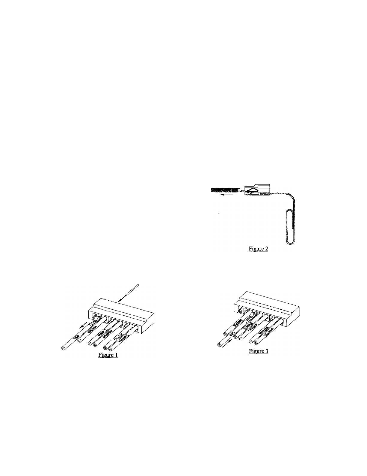
11. Pull the red wire out of the slot.
12. Insert the red wire into slot number 4 until the
terminal clicks into the housing. Gently pull on the
wire to ensure it is fully seated in the housing.
10. In slot number 2, insert a small wire (paper clip)
between the locking tab of the red wire terminal and
the housing. Note: The locking tab is located in the
small rectangular slot below the terminal. DO NOT
push down on the contact prongs on the wire
terminal.
13. Remove the connector plug from the pump. NOTE:
Removing the pump cover on pumps with an
external cooling fiin will make it easier to access the
connector plug.
14. Connect the nine pin plug from the adapter harness
to the to the SCU.
P/N 131888800 8/99
Page 3

15. Connect the nine pm plug removed in step K to the
connector board on the adapter harness.
16. Dress the adapter harness ttiong side of the present
washer itarness as sliowai.
17. Connect the green connector plug from the adapter
harness to the pump. Re-mstall the pump cover, jf if
was removed in step 1.3.
IS, Connect the green connector plug from the washer
harness to the connector on the adapter harness.
19. NOTE: If the service kit's door lock is already pre
wired to the adapter harness, go to step 20. If the
service kit’s door lock is not pre-wired to the adapter
Irarness, connect the adapter harness connections to
the new door lock.
20. Matching color for color, connect the door switch
wires from the washer harness to the connectors in
tlic adapter harness,
21. Install the new door lock to the washer cabinet using
the same screws removed in step 6.
22
. Using the plastic harnes.s ties, attach the adapter
harness to the washer harness. fJress the harness in
such a manner that it will not interfere with any
moving parts or cause any noise when the washer is
in operation.
Connect the washer to the electrical power source
and lest for proper operation. Close the door, place
the timer to the final spin position, and start the
timer. When the machine starts its fast ramp up to
lire higher spin speed, turn the timer off, then
quickly pull on the door handle to verify the door is
locked. If the door opens, recheck the connections in
steps 9 through
1
?..
Using the tube of adhesive, glue the bellows to the
front panel at the 2, 3, & 4 o’clock positions. Wait
about two minutes, then pull on the bellow to make
sure it is securely bonded to Ihe iront [lancl.
Install the front service panel.
O'N 131 SKSHOO S.'‘)v
 Loading...