

Page 1

Operating & Safety
Manual
Robomow
RL500 / RL550
RL800 / RL850
www.friendlyrobotics.com
DOC0012A
Page 2

EC Declaration of Conformity
1.
F. Robotics Acquisitions
declares that the machines described in item 2 conforms with the directives listed in items
3 &
4.
2. Product: 24 Volt Battery operated automatic lawn mower,models RL500, RL550, RL800 and
RL850*.
Serial number: see mark on the machine.
Tested by the British Standards Institude (BSI) to comply with The supply of Machine (Safety)
3.
Regulation 1992 Essential Health and Safety Requirements relating to the design and
, 1 Ha’yassur St., Hasharon Industrial Park, Kadima, Israel
construction of machinery.
The following European standards were taken into consideration when testing the machine:
EN 292: Parts 1 and 2:1991, Safety of Machinery - Basic concepts, general principles for
design.
EN 294: 1992, Safety of Machinery - Safety distances to prevent danger zones being reached
by the upper limbs.
EN 418:1992, Safety of Machinery - Emergency stop equipment, functional aspects Principles for design.
EN 60204: Part 1:1997, Safety of Machinery - Electrical equipment of machines - general
requirements.
EN 60335: Part 1:1994, Safety of household and similar electrical appliances.
In addition the following National standard and draft were taken into consideration when
testing the machine:
BS 3456: Part 2: Section 2.42: 1997, Safety of household and similar electrical appliances Section 2.42 Battery-operated lawnmowers.
PrEN 50338: 1999, Safety of household and similar electrical appliances –Particular
requirements for pedestrian controlled battery powered electrical lawnmowers.
Noise level testing was conducted to the requirements of: 79/113/EEC and 88/181/EEC.
Results are published by BSI in report number 282/4077203 dated 14 July 2000.
Marylands Avenue, Hemel Hempstead, Hertfordshire HP2 4SQ, UK.
4. Also tested by Hermon Laboratories to comply with The Electromagnetic compatibility
directive 89/336/EEC. Results are published By Hermon Laboratories in report number
Frienmc_EN.14123 dated 21 June 2000.
Rakevet Industry Zone, Binyamina, 30550, Israel.
5. Measured sound power level: 85 db.
6. Guaranteed sound power level: 90 db.
7. Technical documentation kept by Mr. Dedy Gur, QA director.
I hereby declare that the above product conforms to the requirements as specified above.
*The original RL500 was tested by BSI in 2000. All Friendly Robotics models currently sold were
tested by F.Robotics Acquisitions Ltd.
Issued at Shai Abramson – Senior VP R&D
Kadima, Israel
___________________
Page 3
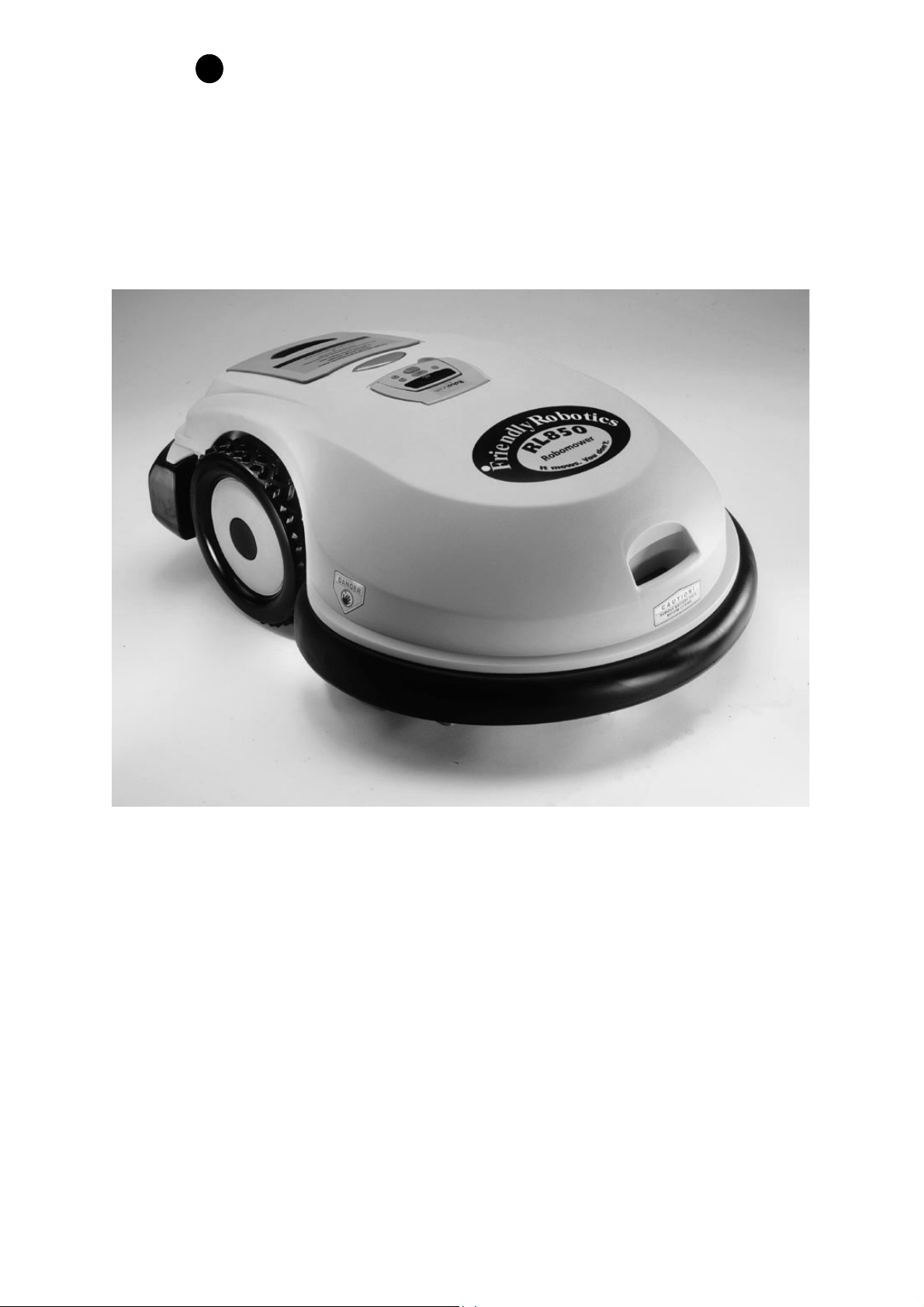
FriendlyRobotics
•
FriendlyRobotics, 2003-A Eur. All rights reserved. No part of this document may
be photocopied, reproduced, electronically or otherwise or translated without the
•
prior written consent of FriendlyRobotics.
Product, product specifications and this document are subject to change without
notice. All other trademarks are the property of their respective owners.
CE approved
Page 4
Welcome
Page 2
FriendlyRobotics
Welcome…
Welcome…
Welcome…Welcome…
for purchasing our product. We know that you will enjoy the extra free time you will have while
using Robomower to mow your lawn. When installed and used properly, Robomower will
operate safely on your lawn and provide you with a quality of cut matched by few mowers of
any kind. You will be impressed with your lawns’ appearance and best of all Robomower did it
for you.
To the world of robotic lawn mowing with the FriendlyRobotics Robomower. Thank you
x
IMPORTANT!
The following pages contain important safety and operating instructions.
Please read and follow all instructions in this manual. Carefully read and
review all safety instructions, warnings and cautions contained in this manual.
Failure to read and follow these instructions, warnings and cautionary
statements may result in severe injury or death to persons and pets or damage
to personal property.
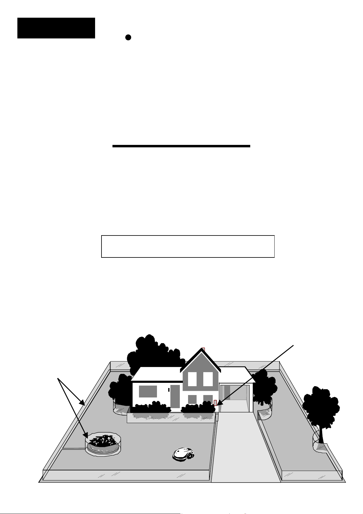
A small wire, called the perimeter wire, is placed around the perimeter of the lawn and any other areas
where you do not want the mower to enter. A small signal is generated from a device attached to the
perimeter wire, called the Perimeter Switch. When turned on, this signal is carried through the perimeter
wire, creating what we define as a virtual wall. The virtual wall is visible only to the Robomower, keeping
the Robomower where you want it, on your lawn. The perimeter switch must be turned on to activate the
A Basic How It Works
perimeter wire before the Robomower will operate.
Perimeter switch turned
on to generate signal
Virtual wall, visible
only to the
Robomower.
Page 5

SAFETY
Page 3
Safety Warnings & Precautions
1. Read the owners/operating manual carefully and follow all
safety and warning instructions.
2. Keep bystanders, children and pets away from mower when in
operation.
3. Never allow anyone to ride or sit on mower.
4. Never allow children or persons not familiar with the safe
operation of the mower to operate the mower.
5. Keep hands and feet away from the cutting blades and other
moving parts.
6. Never attempt to service or adjust the mower while it is in
operation.
7. Inspect and clear the mowing area of all debris before
operating the mower.
8. Never raise the mower or attempt to inspect the blades while
the mower is operating.
9. Always remove the power pack before lifting the mower or
attempting any adjustments.
10. When operating the mower in manual mode, maintain a safe
distance from behind or around the mower and wear proper
foot apparel.
11. Do not operate the mower on slopes greater than 15 degrees
or use it in manual operation on slopes where a firm footing is
not possible.
12. Do not operate the mower if any safety feature or device is
damaged or inoperable.
13. Do not attempt to disable or defeat any safety feature or
device.
14. Use heavy gloves when inspecting or servicing the blades.
15. The charger is for indoor use only. Do not use in areas where
moisture or water is likely.
16. Wear eye protection and use gloves when installing the
perimeter wire and driving the wire stakes/pegs.
Page 6

SAFETY
Page 4
Safety Warnings & Precautions
Warning Decal Definitions
1
1. WARNING-this is a dangerous power tool. Use care when operating and
follow all safety instructions and warnings.
2. Read the owner/operating manual carefully and follow all safety
instructions.
3. Objects can be thrown from mower while operating, take caution.
4. Keep children, pets and bystanders away from mower.
5. Sharp rotating blades. Keep hands away and do not attempt to lift
mower from this area.
6. Sharp rotating blades. Keep feet away.
DANGER! Sharp rotating blades. Keep hands and feet away.
CAUTION! Remove battery/power pack before
attempting to lift mower for any reason.
2
3 4 5 6
Serious injury can occur.
Page 7

SAFETY
Page 5
Robomower RL500/RL550/RL800/RL850
Safety Features
1. Child Guard / Safety Guard
This menu option offers a safety feature to help prevent children or others not familiar with the
safe operation of the mower to operate it freely.
2. Lift Sensor
There is a sensor located on the front caster wheel of the mower. In the event the front of the
mower is raised approximately 1-inch from its resting position on the ground during blade
operation, the blades will stop rotating immediately (< 1 second).
3. Sensor Equipped Bumpers
The front and rear bumpers are equipped with contacts that will activate when the mower
strikes a solid, fixed object when that object is at least 6-inches in vertical height from the
supporting surface of the mower. W hen the bumper sensor is activated, the mower will stop
movement in that direction and reverse itself away from the obstacle. In manual blade
operation, bumper activation will stop the rotation of the blades immediately (<1 second).
4. Emergency Stop Switch
Located on the top outer surface of the manual controller, red in color. Pressing this button at
any time during operation will stop all mower movement and stop the rotation of the blades
immediately (<1 second).
5. Automatic Mode Recognition
The Robomower is designed so that it cannot be operated in the manual mode while the
Manual Controller is in its’ pocket and it cannot operate in the automatic mode while the
Manual Controller is removed.
6. Two-Step Operator Presence Control
While in manual mode, it requires two independent finger actions in order to engage the
mower blades. Once engaged, the mower blade button must remain depressed to continue
blade operation. Once released, the two-step engagement process must be repeated.
7. Electronically Controlled Charging System
The Robomower is equipped with an on-board charge control system. This allows you to
keep the charger connected at all times, even after the battery is fully charged. The control
system will prevent an overcharge to the battery and keep it fully charged and maintained for
the next use.
8. Sealed Power Pack
The power pack that operates the Robomower is completely sealed and will not leak any type
of fluids, regardless of position. In addition, the power pack contains a one-time-use fuse in
the event of a short-circuit or power malfunction.
Page 8
SAFETY
Page 6
9. Perimeter Switch and Perimeter Wire
The Robomower cannot operate without a perimeter wire installed and activated through the
Perimeter Switch. In the event the Perimeter Switch is turned off or otherwise fails to function, the
Robomower will stop operating. Likewise, should a break in the perimeter wire occur the
Robomower would again stop operation. A break in the perimeter wire prior to operation will
prevent the Robomower from operating. The Robomower can only operate within the boundary
of the perimeter wire.
10. Auto-Off Perimeter Switch
The auto-off feature of the perimeter switch shuts down the perimeter switch operation after
approximately 5 hours of continuous operation. This is typically 1 to 2 hours after which a fully
charged Power Pack will need to be re-charged. This helps to prevent unauthorized persons from
attempting to re-start the Robomower after it has completed its’ operation.
11. Over-Current Monitoring Protection
Each of the three blade motors and each of the two wheel drive motors are monitored
continuously during operation for any situation that may cause these motors to over-heat. In the
event this is detected, the Robomower will stop operation of at least that motor and possibly the
mower itself and indicate that the motor is cooling down. W hile unusual, this may happen when
the mower is put in grass that is severely overgrown; the underside of the mower is clogged from
poor cleaning maintenance; the mower has encountered an obstacle that is unable to activate the
bumper sensor preventing it from moving; or a problem landscape area has caused the mower to
get stuck and is preventing it from moving.
WARNING!
!
This warning symbol will be found at several points throughout
the pages of this owner/operator manual. It is intended to
highlight an important safety, warning or cautionary message.
Please pay particular attention to these areas and be sure you
fully understand the message before proceeding.
Page 9
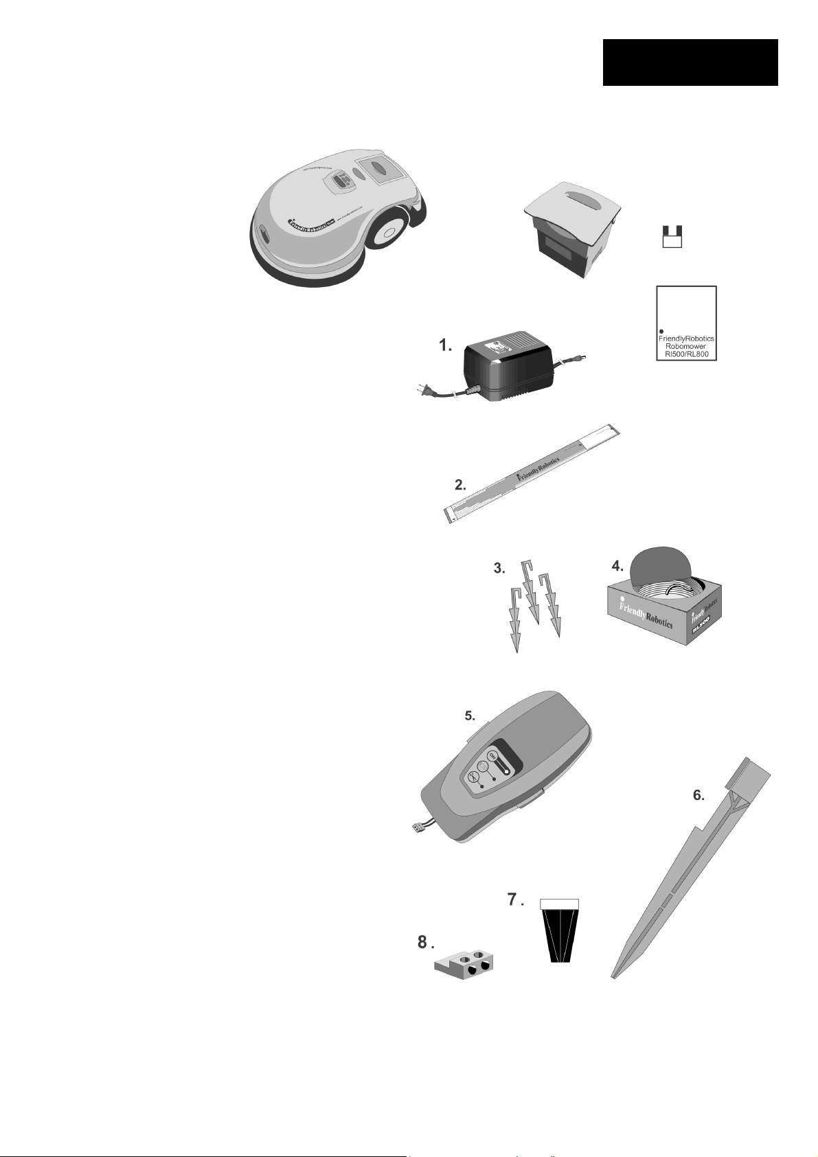
What's in the Box
1. Standard Charger
Used for recharging the Robomower power
pack.
2. RoboRuler
Used for setting the distance of the perimeter
wire from the lawn edge.
3. Pegs
Used for securing the perimeter wire to the
ground around the lawn perimeter and
around obstacles.
4. Wire
Used to create a virtual wall for your
Robomower
5. Perimeter Switch & C-Cell Batteries
Activates the perimeter wire, which defines
the area in which the Robomower will
operate.
6. Perimeter Switch Mounting Stake
Used for supporting the perimeter switch in
the lawn.
7. Wire Connectors
Used for splicing wires (as needed).
8. Plot Connectors
Used for connecting the completed
screwdriver perimeter wire installation to the
perimeter switch.
Robomower
What's in the Box
Power Pack
Page 7
Power Pack Fuse
(Must insert to operate)
Operating
Manual
Operating Manual
NOTE: Tools needed, but not included: hammerwire
cutters, small flat- head screwdriver
Page 10

Table of Contents
Page 8
Table of Contents
Welcome, Basic How It Work ………………………………………………..2
The world of automatic mowing with the Robomower
Safety Warnings and Precautions…………………………………………….3
Safely operating the Robomower
What’s In The Box………………………………………………………………..7
A list and descriptions of the items found in the Robomower box
Chapter 1 – Perimeter Wire Setup…………………………………………….9
Setup of the perimeter wire in your lawn
Chapter 2 – Preparing The Robomower……………………………………..16
How to get the Robomower ready for the first use
Chapter 3 – Automatic Operation……………………………………………..21
Operating the Robomower in automatic mowing (Robotic mowing)
Chapter 4 – Power Pack and Power Management…………………………23
Proper use and maintenance of the Power Pack and charging system
Chapter 5 – Manual Operation………………………………………………. 25
How to use the Robomower in manual mode
Chapter 6 – Settings and Advanced Features……………………………. 26
Settings and features for the customer to choose
Chapter 7 – Messages and Troubleshooting……………………………… 30
Understanding the text messages and troubleshooting
Chapter 8 – Specifications……………………………………………………. 34
General product specifications
Chapter 9 – Care and Maintenance…………………………………………. 35
How to care and maintain your Robomower
Chapter 10 – Accessories…………………………………………………….. 37
Accessories available to enhance the mowing experience
Page 11
Chapter 1
Perimeter Wire Setup
1.0 Where To Start
In order to determine the best location to begin the setup, it is best to first make some basic
decisions based on your lawn. For each zone that is set up, allow for placement of one
Perimeter Switch for that zone. Find a convenient spot outside the perimeter of each zone that
is relatively easy for you to access. A spot sheltered from the elements is preferred
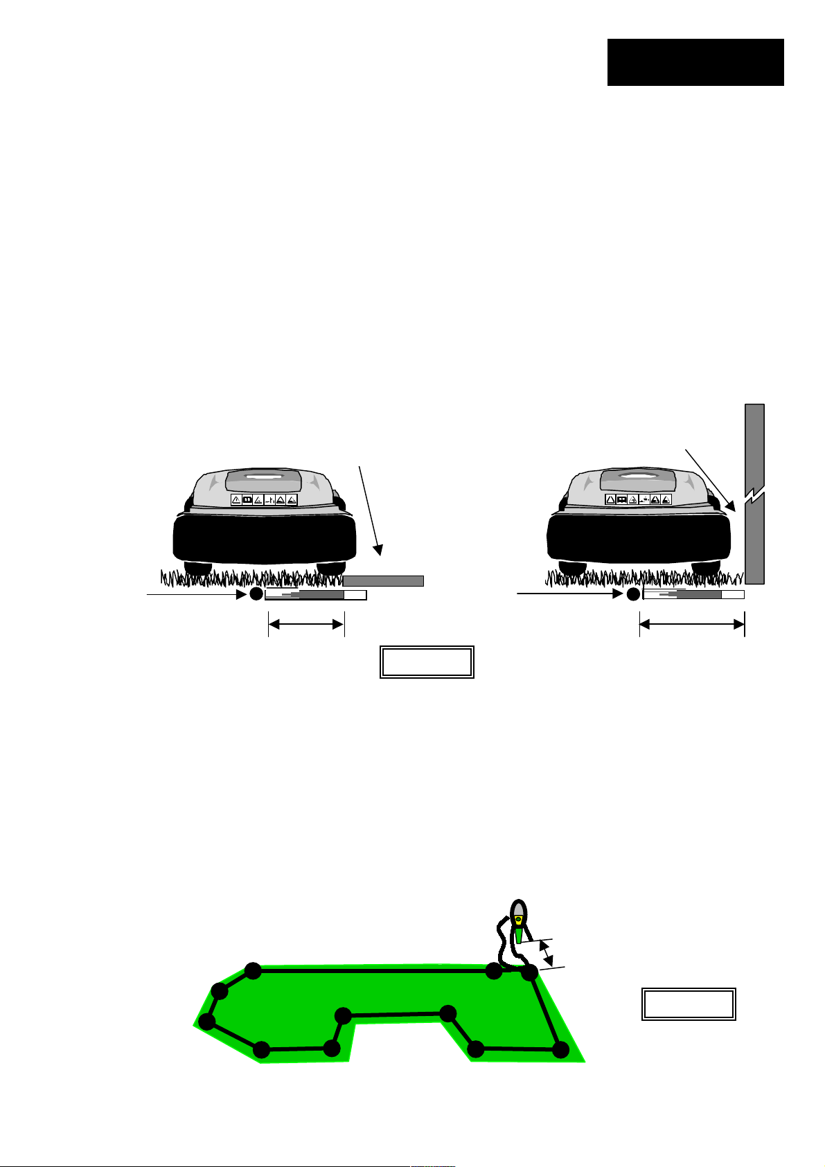
1.1 Using The RoboRuler
There are two basic measurements that are used on the RoboRuler. The shorter distance is
used along perimeter edges where the area outside the immediate perimeter (about 12 inches/30
cm) is free of obstacles and is the same relative height as the perimeter edge. The longer
distance is used along perimeter edges where the area outside the immediate perimeter has
obstacles or differences in the height along the perimeter edge. See Figure 1.1.
Perimeter
wire
position
1.2 Starting The Perimeter Wire
Area outside perimeter. Same
basic level and free of obstacles.
Short distance Long distance
Figure 1.1
Tear out the perforated center piece on the perimeter wire box. Puncture the plastic covering
with your finger and feel around inside the center of the wire spool for the end of the wire. Pull
the wire end out of the box. The box is designed as a dispenser for the wire so do not remove
the wire spool from the box. After reviewing the illustrations and instructions in the following
pages you will be ready to lay out the perimeter wire and start pegging it to the ground. Figure
1.2
Leave enough wire at the beginning, where the Perimeter Switch is going to be located. Use the
RoboRuler to help guide you on placement of the wire along the perimeter. Use a minimum
number of pegs at this point, as you will want to test the wire position at the end of the setup.
See Section 2.5 for details on testing the setup.
Area outside perimeter. Has a wall
as an obstacle.
Perimeter
wire
position
>5ft (1.5m)
Chapter 1
Page 9
Figure 1.2
Page 12

Chapter 1
Page 10
1.3 Fastening The Wire To The Ground
WARNING!
Damage to the eye is possible. Use proper eye protection
and wear appropriate work gloves when hammering the
pegs. Hard or dry ground may cause pegs to break when
driving them in. In extreme cases, watering the lawn where
the pegs will be driven can be beneficial.
!
Add pegs in to pull the perimeter wire down to the ground surface, below the grass tips Figure
1.3
Perimeter Wire
Add pegs in to pull the perimeter wire
down to the ground surface, below the
grass tips.
1.4 Corners & Sharp Turns
Care must be taken not to create a turn sharper than 90 degrees when setting up the perimeter
wire. A turn sharper than 90 degrees can cause the Robomower to lose track of the perimeter
wire. In situations where a corner may require a wire placement of less than a 90-degree angle,
placement can be adjusted using several angles to avoid this. See Figure 1.4.
Figure 1.3
Correct corner
setup using several angles
to avoid a less than 90-
degree angle.
Lawn area
Figure 1.4
Incorrect corner
setup
90 degrees
Page 13
1.5 Narrow Areas And Narrow Passes
The minimum distance for an effective narrow pass is 5.5 feet (1.7 m) between perimeter wires.
Figure 1.8.
1.6 Defining Obstacles-Perimeter Islands
Many obstacles can be left in the lawn without consideration to excluding them using the
perimeter wire. The basic rule of thumb is that the obstacle must be at least 6 inches (15 cm)
high from the ground and the obstacle must be relatively rigid. Good examples of these kinds of
obstacles include many trees, phone poles, power poles and flag poles.
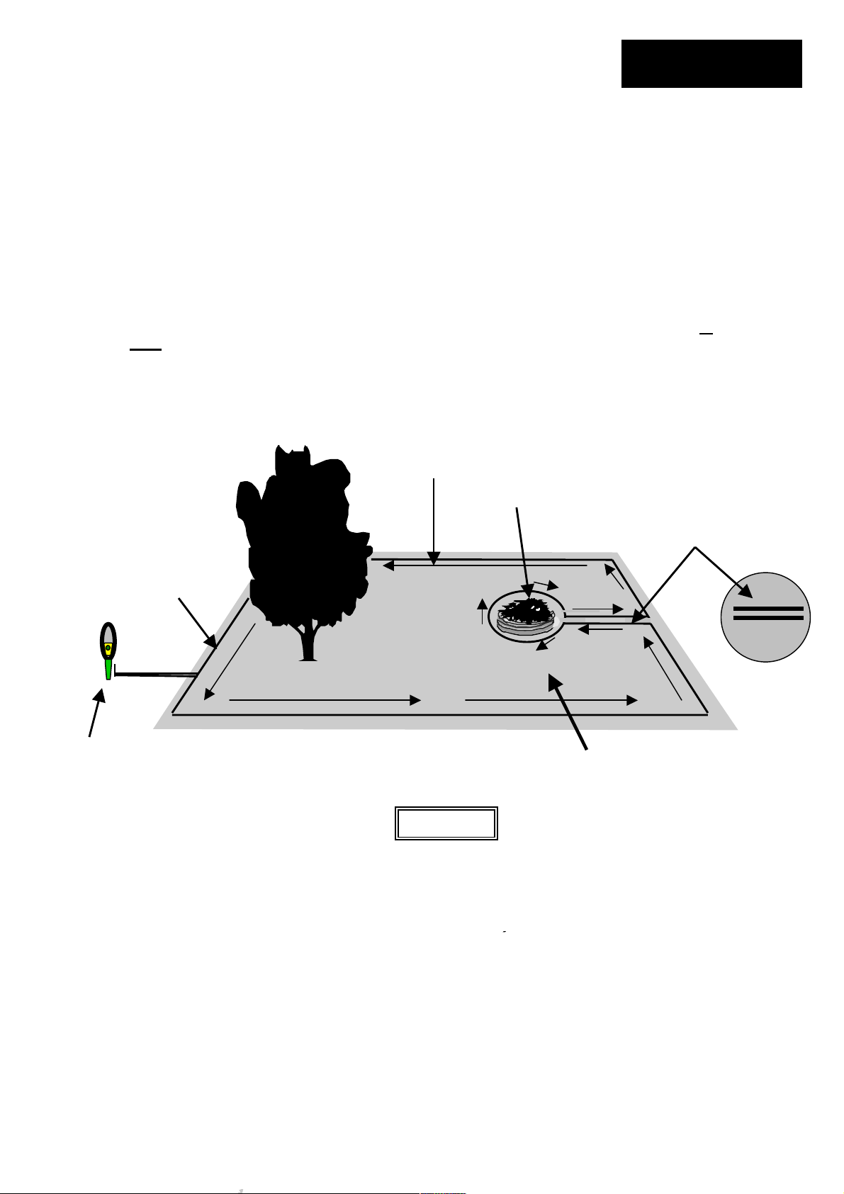
To create a perimeter island, take the wire from the perimeter section closest to the obstacle and
peg the wire around the obstacle, returning back to the same spot of the perimeter. There are
two keys to setting up the perimeter wire to exclude an obstacle; 1) the two wires going to
from
the obstacle should be placed under the same peg (touching) and 2) follow the direction of
set up as shown in Figure 1.6.
Perimeter
wire
Perimeter switch placed at least 5 feet
(1.5 m) from perimeter. Wires to
perimeter switch should be placed
adjacent, the same as wires leading to
an obstacle.
Direction of
set up
Flower bed
Direction of set up
followed around
Figure 1.6
Chapter 1
Page 11
and
While the picture shows two
wires separate, they should
be adjacent and no more than
1/8 inch (3 mm) from one
another
obstacle
Page 14
Chapter 1
Page 12
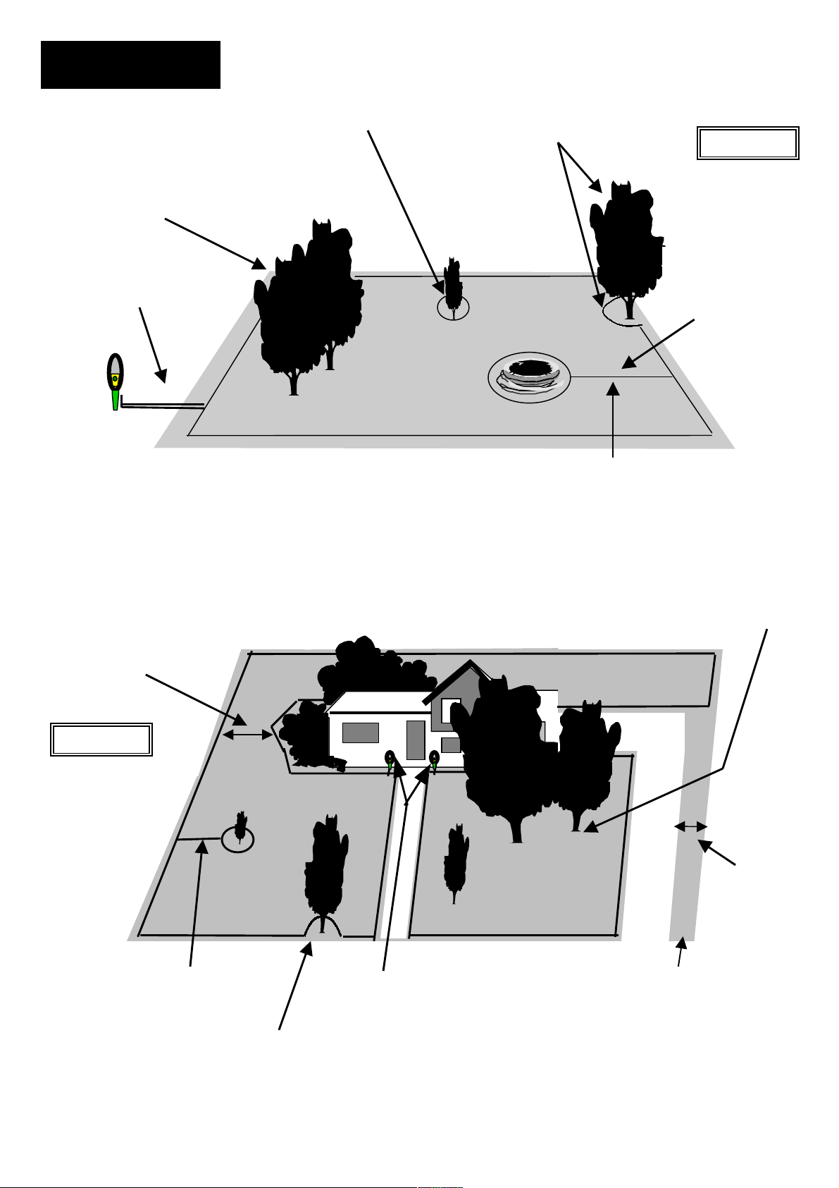
Trees large enough to allow
Robomower to bump into do
not require a perimeter wire
around it
Greater than 5 feet
(1.5 m)
Narrow passes should
be at least 5.5 feet
(1.7 m) between wires
Figure 1.8
Distance greater
than 4 feet (1.2 m)
Closer than 4 feet (1.2 m) to
perimeter wire, loop out
Zone one
Small tree, must
exclude with
perimeter wire
The Robomower can freely move across this section, but will still
recognize the perimeter island. By allowing this, multiple
obstacles in a given lawn will have little effect on free movement of
Perimeter
Switches > 5 feet
(1.5 m) from
perimeter
Tree too close to
perimeter, less than 4
feet (1.2m), loop out
with perimeter wire
the Robomower or its’ efficiency.
Large trees, OK to be treated as an
Zone two
obstacle and not excluded with the
perimeter wire. Be sure they are at
least 4 feet (1.2m) from the perimeter.
Width must be greater than 5.5
feet (1.7 m), measured from
perimeter wire to perimeter wire
Figure 1.7
Minimum distance
between obstacle
wire and perimeter
wire = 5 feet (1.5 m)
3 feet
(0.9 m)
wide
Page 15
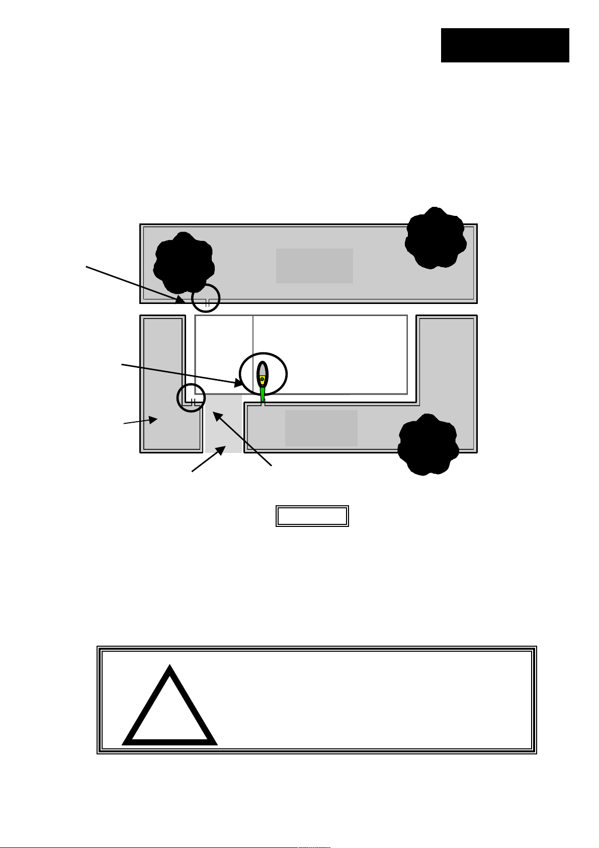
1.7 Multiple Zones/Areas
As mentioned earlier, your home may require more than one zone to be set up in order for the
Robomower to work in all of your lawn effectively W here grass areas are not contiguous, or are
separated by fences or other objects, it is also recommended to make each of these a separate
zone.
Perimeter Switch
location 2
Perimeter Switch
location 1
Side yard
Zone C
1.8 Slopes
The maximum slope limit is 15 degrees. If you are unsure as too whether a slope is too steep or
not, attempt driving the Robomower manually up the slope. If the front of the mower does not lift
from the ground, the slope is fine to include in the cutting area. If however it does lift, exclude
this section from the cutting area.
Perimeter switch can be moved between different zones or you
can use one switch for each zone.
Back yard
Zone B
Driveway
House and garage
Front yard
Zone A
Perimeter Switch
location 3
Figure 1.9
WARNING!
Severe injury can occur. When attempting to mow sloped
areas that are too steep for automatic operation of the
Robomower, insure that you can maintain a safe and sure
footing before attempting to mow. Cut across slopes for
safety. Always wear appropriate closed toe shoes when
!
operating the Robomower manually.
Chapter 1
Page 13
Page 16
Chapter 1
Page 14
1.9 Completing The Setup
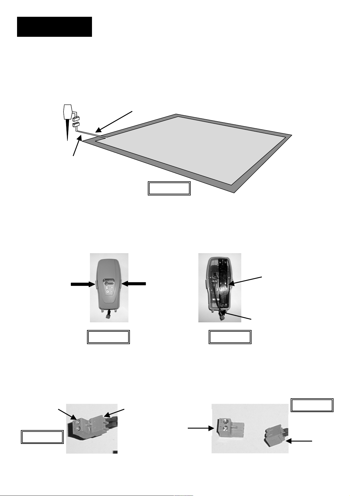
Once the perimeter wire is completed and pegged to the ground, the last step to complete is
attaching the Perimeter Switch to the perimeter wires and testing the setup. Figure 1.12
Note that the wires are adjacent and touching leading from the
perimeter to the Perimeter Switch. Peg firmly to the ground leading
away from the perimeter and towards the switch location
Two wire ends from
perimeter setup.
Switch > 5 feet (1.5 m)
from perimeter.
Figure 1.12
After installing the batteries, Figure 1.13, be sure the wire lead coming out of the Perimeter Switch is
positioned at the small notch in the bottom of the housing before fully snapping the Perimeter Switch
back together. Figure 1.14.
Squeeze at arrows to
remove cover
C-cell batteries,
place in battery
holder
Small notch for
wire lead
Figure 1.13
Figure 1.14
The lead coming from out of the Perimeter Switch has a female connector permanently attached. It is
one part of a two-part connector. Figure 1.15 and 1.16. Plug the perimeter wire connector into the
Perimeter Switch and press the ‘ON’ button.
Perimeter Switch
connectors attached
Perimeter Switch
connectors unfastened
Male
Female
Male- to
perimeter wire
Figure 1.15
Female side-
to Perimeter
Switch
Figure 1.16
Female- to
Perimeter
Switch
Page 17
Chapter 1
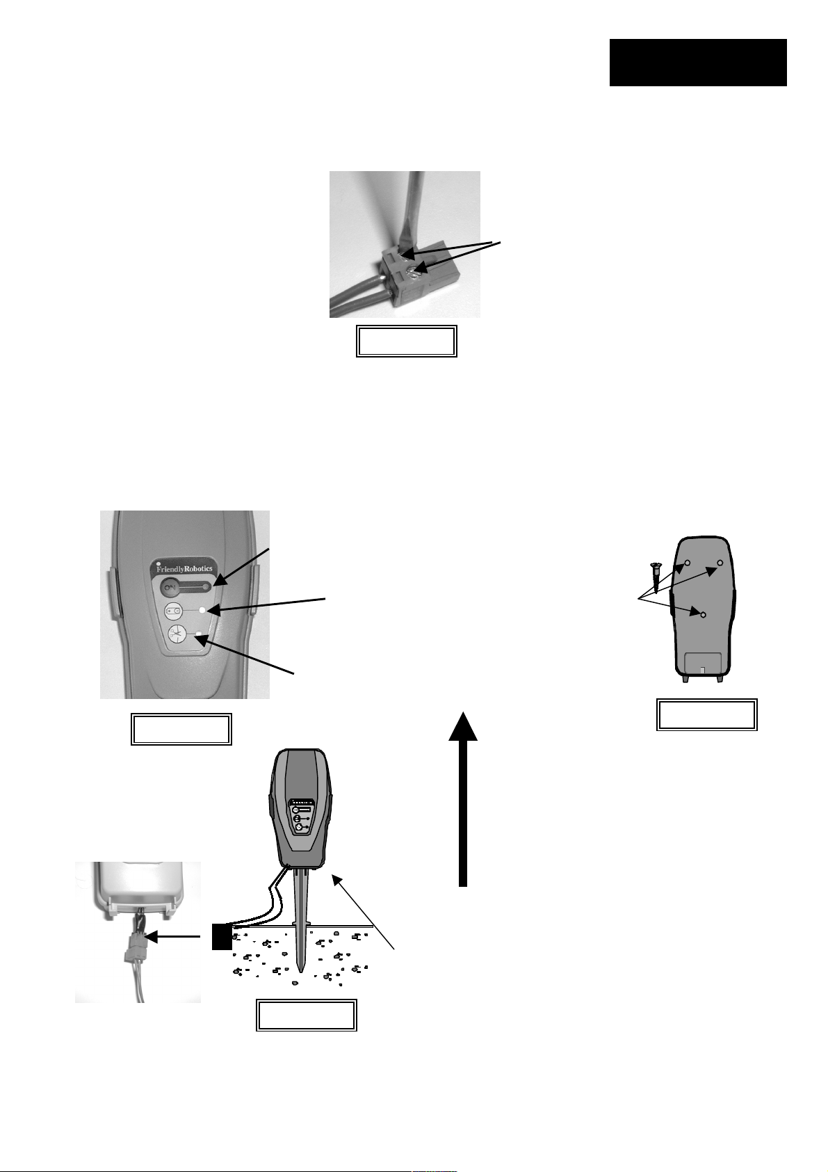
Insert the two perimeter wire ends into the male connector as shown in Figure 1.17. Using a small flat
blade screwdriver, fasten the two screws tightly to hold the wire. Figure 1.17.
Strip back ¼ inch (6 mm) of insulation
from each wire end and insert each
perimeter wire end into hole of
connector.
Using a small flat blade
screwdriver, tighten these
two screws to secure the
perimeter wires into the
connector
Figure 1.17
A small flashing green light next to the ‘On’ button indicates the system is on and functioning
correctly. Figure 1.18. The Perimeter Switch also has an indicator for low batteries and for a
disconnected/broken perimeter wire. Figure 1.18. The Perimeter Switch has an automatic shutoff
feature, eliminating the need for you to turn it off after each use. It will shut itself off after 5 continuous
hours of operation. Place the Perimeter Switch on the stake as shown in Figure 1.19 or mount on a
fixed surface as shown in Figure 1.20.
On button and
indicator light
Low battery
indicator light
Mounting the Perimeter
Switch using three
mounting bosses on
back cover
Disconnected/broken
wire indicator light
Figure 1.18
The Perimeter Switch MUST be mounted
vertically in order to maintain its’ water
resistance
Page 15
Figure 1.20
Figure 1.19
Perimeter Switch with
mounting stake attached.
Disconnect Perimeter Switch
connector and move switch to
new plot.
Page 18
Chapter 2
Page 16
Chapter 2
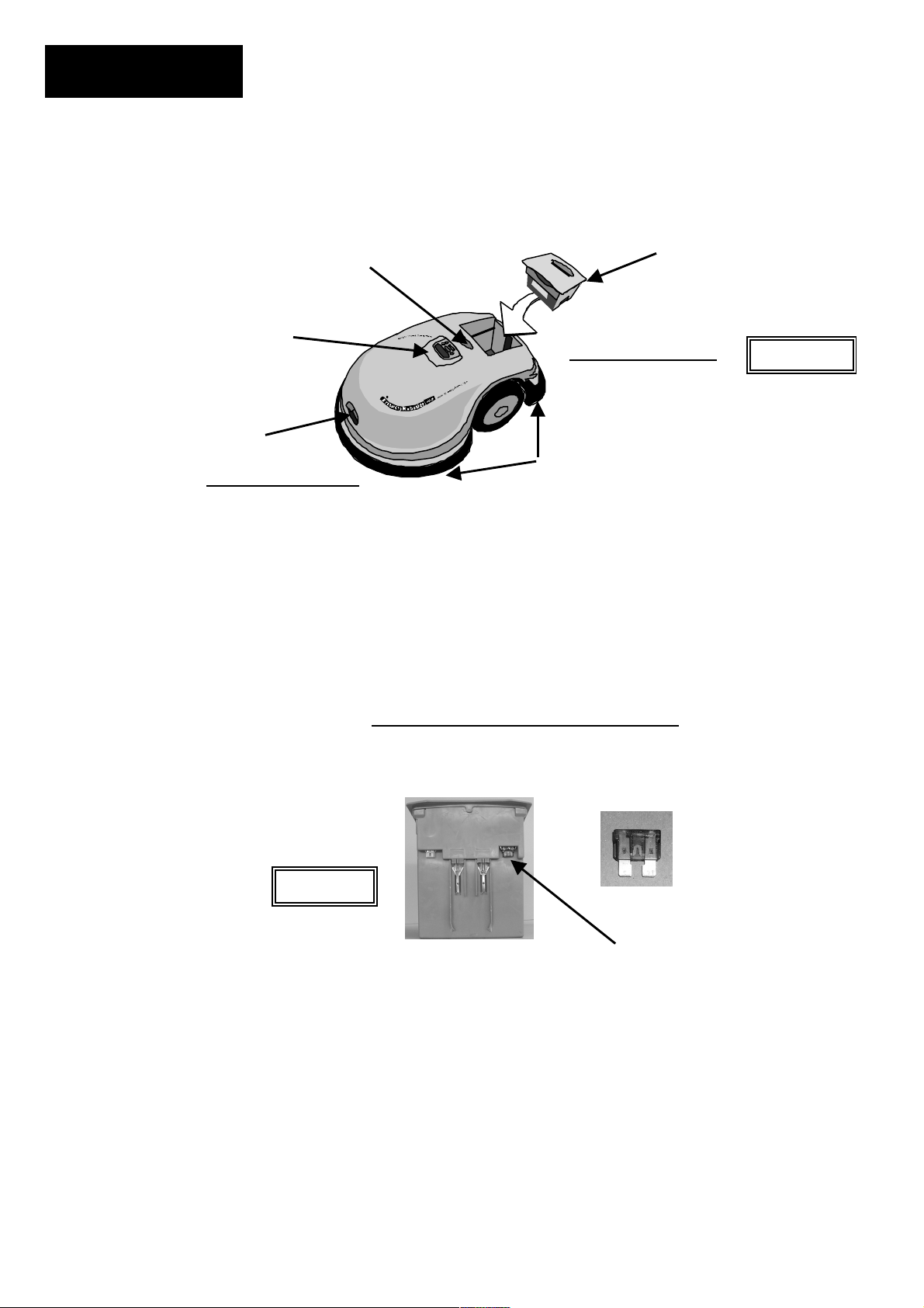
Preparing The Robomower
Blade operating lamp
Power Pack
Manual Controller
Rear of Robomower
Carrying handle
Front of Robomower
Bumpers with touch sensitive sensors
A basic ‘what is what’ on the Robomower
2.1 Inserting Power Pack Fuse
Carefully lower the Power Pack into the Robomower. After inserting the Power Pack back into
the Robomower. See Chapter 4, Power Pack Charging & Power Management
the Power Pack and charging.
Figure 2.1
Insert the Power Pack fuse into the
fuse holder. The fuse can be
for more details on
inserted in either direction
Figure 2.0
Page 19
Chapter 2
Page 17
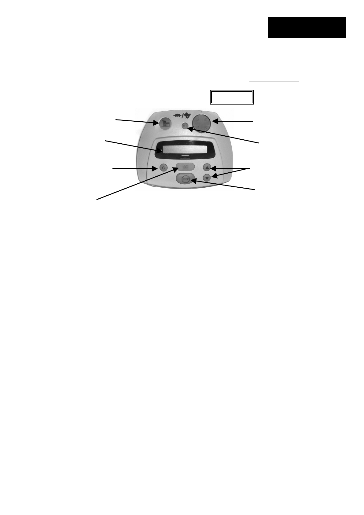
2.2 Using The Manual Controller
The Robomower is equipped with a Manual Controller. It allows you to manually drive and
operate the mower. To get started on using the Manual Controller, study figure 2.2 to view the
various operating controls and their functions. Refer to Chapter 5, Manual Operation
details regarding use of the Manual Controller.
Figure 2.2
1. Manual blade
engagement
button
2. LCD display
window
3. Clear/cancel
button
R
Manual
User Options
4. GO/Start
button
1. Manual blade engagement button – engagement of the blades in manual requires two
distinct button operations in order to operate.
2. LCD window display – displays the text messages using a Liquid Crystal Display (LCD).
Also shows current battery status.
3. Clear/cancel button –This button is used to cancel a selection shown in the LCD window
when making user selections. It is also used as a means to reverse back out of the menu
options that can be accessed in user options, returning you to the main screen.
4. GO/Start button – the main operating button for automatic operation. In addition it is used as
a button for making or confirming selections made under user options in the LCD window.
5. Stop button – pressing this button will stop all operation of the blades and wheel motors
when in the automatic operation mode. It can also be used to stop an operation in progress
before it has commenced.
6. Scroll for menu selection –The arrow button, up and down, allows you to scroll through
these different options.
7. Manual drive speed control – the manual drive function is equipped with two ground
speeds, fast and slow. In order to change the ground speed, press the button once to move to
the opposite speed of travel
8. Navigation button – pressing this button in the desired direction will allow manual driving of
the mower. Use light pressure on the navigator pad, gently rolling it to the desired direction of
travel for driving. The drive button is omni-directional in forward and reverse and constant
pressure must be maintained for continued operation.
8. Navigation
button
7. Manual drive speed
control – fast/slow
6. Scroll arrows for
menu selection
5. Stop
button
for full
Page 20
Chapter 2
Page 18
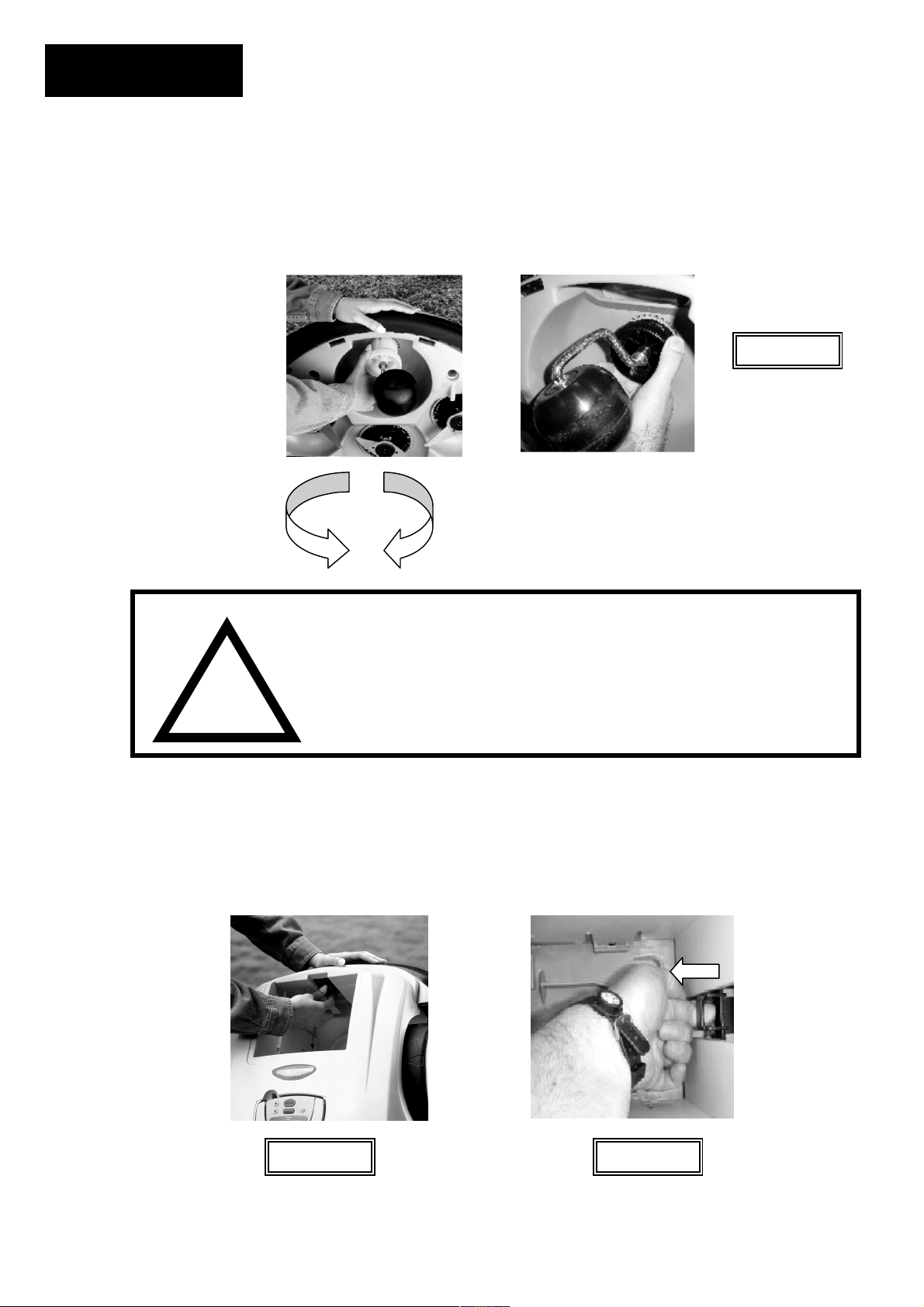
2.3 Setting The Cutting Height And Ground Clearance
Remove the Power Pack before making any adjustments. The Robomower has two basic
adjustments, cutting height and ground clearance. The cutting height adjustment is located at the
front wheel and is controlled by rotating the front wheel hub in or out, which effectively causes the
front wheel to be raised or lowered. See Figure 2.6.
Rotate the front wheel
(higher) to adjust the
cutting height. Each
click represents about
hub in (lower) or out
1/4 inch (6 mm) in
height of cut.
Rotate this
direction for
higher cut
WARNING!
The ground height adjustment is located in the Power Pack compartment of the mower. See
Figure 2.7. It has two positions, upper and lower. (RL550 Europe has three; upper, lower and
middle) The lower position (closest to the bottom of the Power Pack compartment) provides the
highest level of ground clearance while the upper position (farthest from the bottom of the Power
Pack compartment) provides the least amount of ground clearance. See Figure 2.8.
Rear ground height
adjustment is located
in the Power Pack
compartment.
!
Figure 2.6
Rotate this
direction for
lower cut
Severe injury is possible. Always remove the Power Pack when attempting
to adjust the height of cut or otherwise lifting the mower off the ground.
Never lift the mower or attempt to adjust the cutting height during
operation. Blades are very sharp and severe cuts or lacerations are
possible. When working around or near the blades always wear heavy
gloves.
Figure 2.7 Figure 2.8
To adjust ground
clearance, pull
out on tab as
shown and slide
tab up or down.
Page 21
Chapter 2
Page 19
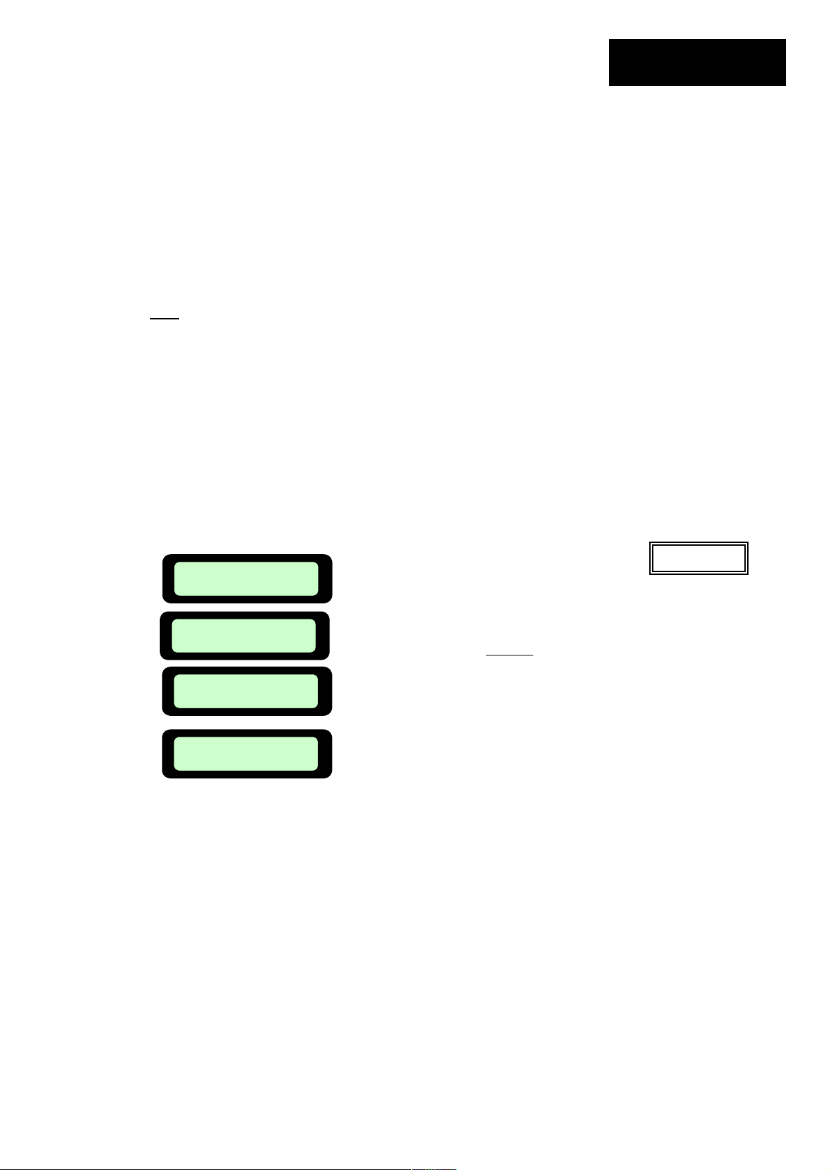
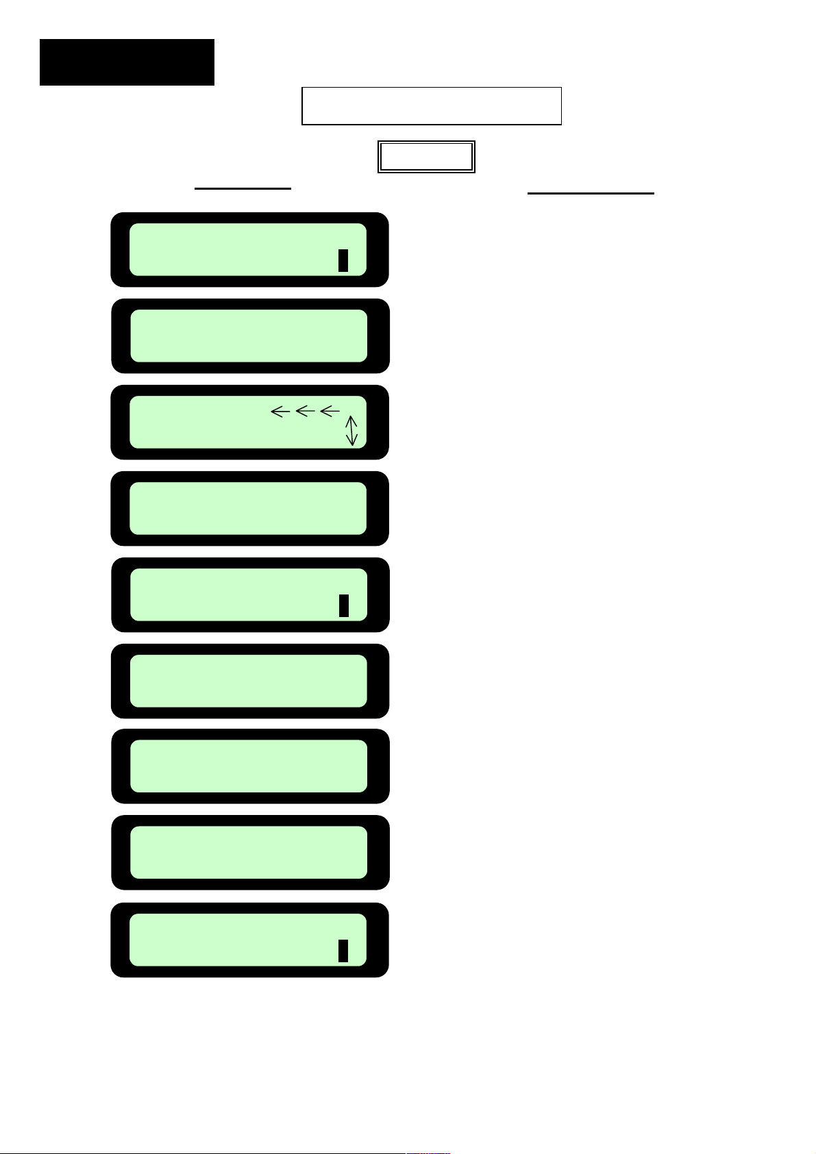
2.4 Set Country and Perform One Time Calibration
The one time calibration process is simple and the Robomower is designed to ask you to perform
this step before it can ever be used in the automatic mode.
x Remove the Manual Controller
x Drive the Robomower to a flat and level section of the lawn, at least 4 feet (1.2 m) from
the perimeter wire
x Insert the Manual Controller in the holder and pivot it down flush
x Turn on the Perimeter Switch
x Follow the calibration setup process as shown in Figure 2.10. (next page)
Note
: If the calibration was not successful, the display will read ‘Restart Elsewhere’. Drive
the Robomower to another flat and level surface within the lawn, at least 10-15 feet (3 – 4.5
M) from the first spot and repeat the calibration process as outlined above.
2.5 Testing Wire Position for Edge Mowing
As mentioned in Chapter 1, it is best to test the position of the perimeter wire on edge mowing to
determine if any small adjustments need to be made to the wire position before driving the rest of
the wire pegs into place. Remove the Manual Controller from the holder and follow the steps in
Figure 2.9 to turn off the mowing blades for this test. Repeat this process to turn the blades back
on once you have completed this test.
x Position the Robomower towards the perimeter wire.
x Insert the Manual Controller back into the holder and pivot down flush
x Confirm the Perimeter Switch is turned on
x Press the ‘GO’ button once. The Robomower will drive to the perimeter wire and begin
tracking for edge
x Walk along the mower while following the edge. Note places where the wire should be
adjusted; the Robomower bumps into an object or wall along edge; the mower is not cutting
far enough onto adjacent surfaces like the driveway; or areas where the mower may drop off
into an adjacent area that is lower than the mowing surface.
x Slightly move the wire in these locations
x Once the test is completed and you are satisfied with the wire position, add in pegs along the
wire where the wire is not pulled down to the ground level.
Manual
User Options
User Preferences
Press GO
Mowing ON
Press GO
Mowing Off
Confirm
Press ‘GO’, then use the Up or Down
arrow keys to scroll until the next screen,
Use the Up or Down arrow keys
to scroll to the off position and press
Press ‘GO’
Mowing
is found.
‘GO’
Figure 2.9
Page 22
q
Chapter 2
Page 20
Zone A: Time: MAX
Set Country
Not Set!
USA
Zone A: Time: MAX
Calibration Re
Activate Motors
Test Passed
Zone A: Time: MAX
LCD Display
Press GO
Press GO
Scroll
Confirm
Press GO
Press GO
Press GO
Press C
Press GO
Calibration Setup Sequence
Figure 2.10
Action Required
Press ‘GO’
Press ‘GO’
Scroll up or down to
find your country
Press ‘GO’ to confirm
selection
Press ‘GO’
Press ‘GO’
Press ‘GO’. Process
will begin and last 1-2
minutes.
Press ‘C’ button
Ready for mowing
Page 23
Chapter 3
Automatic Operation
3.1 Activating The Perimeter Switch
The Robomower cannot operate unless the Perimeter Switch is turned on and the mower is on
the inside of the active perimeter. Press the ‘ON’ button to turn on the switch. You will hear one
short beep when the switch is first pressed, indicating it is on. If one of the other indicators is on
refer to Chapter 7, Text Messages and Troubleshooting
WARNING!
!
3.2 Positioning The Robomower On The Lawn
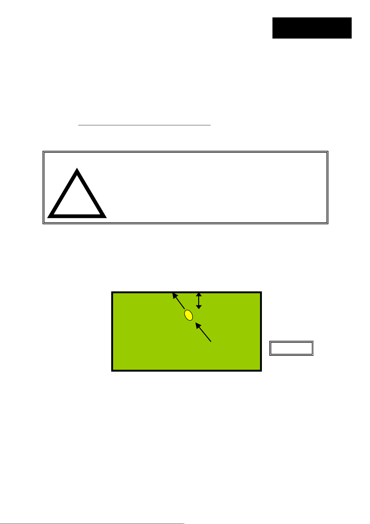
Remove the Manual Controller from its’ holder and drive the Robomower into the lawn area to be
cut. Position the Robomower at least 3 feet (1 m) from any straight length of perimeter wire, with
the front of the mower pointing to the perimeter wire. Figure 3.1.
3.3 Edge Mowing
The first mowing chore for the Robomower is mowing the edge.
x Place the Manual Controller in the holder and pivot down flush
x Press the ‘GO’ button once to start the automatic mowing sequence
x The Robomower will automatically follow the perimeter wire one to two passes around
the perimeter and will automatically turn into the lawn to mow the inner area
Serious injury or death can occur. This machine has sharp
rotating blades. When operating in automatic mode, keep
children, pets and bystanders away from mower. When
operating automatically, do not leave unattended if children,
pets or other persons will come in contact with the mower
during operation. Never allow persons or pets to ride on this
machine or block the path of travel.
Front pointed to
perimeter wire
for further help.
3 feet (1 m)
Starting
point
Figure 3.1
Chapter 3
Page 21
Page 24
Chapter 3
Page 22
3.4 Scanning (Mowing)
Keep in mind that the Robomower will not mow all the grass on its first pass, in fact it will leave
uncut grass in between many of the legs it makes. This is expected and is entirely normal.
These uncut areas will be cut on subsequent passes of the Robomower across the lawn. Just
like a dishwasher, wait until the job is finished before you can appreciate the results. The
Robomower will continue to run for the amount of time selected or for the default ‘MAX’ time,
which is generally 2.5 to 3.5 hours, depending on grass type and condition. (RL550 Europe 2
hours) See Chapter 6, Operator Settings and Advanced Features
operating time.
Note: There is an option to skip the edge mowing and to start scanning (mowing) the main area
of the lawn. Simply press the ‘GO’ button two times in sequence when starting the mower.
3.5 Mowing Complete
When the Robomower has operated the allotted time, it will simply stop in the lawn, waiting for
you to drive it back home and plug it into the charger, ready for the next mowing session. The
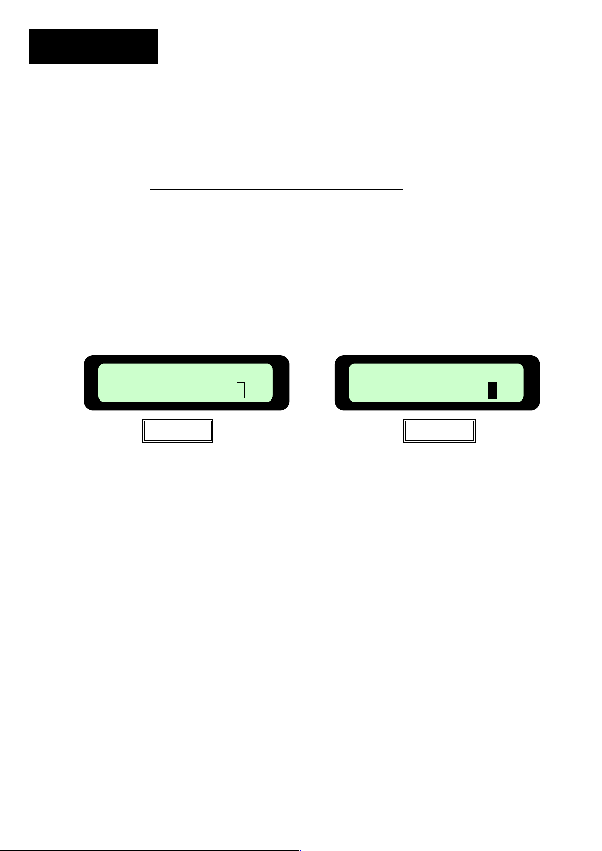
LCD will display a text message as seen in Figure 3.7 if the mowing time is set to the default time
of ‘MAX’ or the message as shown in Figure 3.8 if the mowing time has been selected to any
time other than ‘MAX’.
If the Robomower has completed its’ mowing and it is more than 20 minutes before you arrive to
move it, the LCD screen will be blank. The Robomower will shut itself down into a sleep mode
after 20 minutes of inactivity at all times. This is an energy saving feature. Pressing the ‘GO’
button or removing the Manual Controller from the holder will ‘wake up’ the Robomower and
display the message that was on the LCD when it went into sleep mode. In this case, either the
message in Figure 3.7 or 3.8.
Recharge Battery
Figure 3.7
for more detail on setting
Time Completed
Figure 3.8
Page 25
Chapter 4
Chapter 4
Power Pack Charging
&
Power Management
4.1 Charging
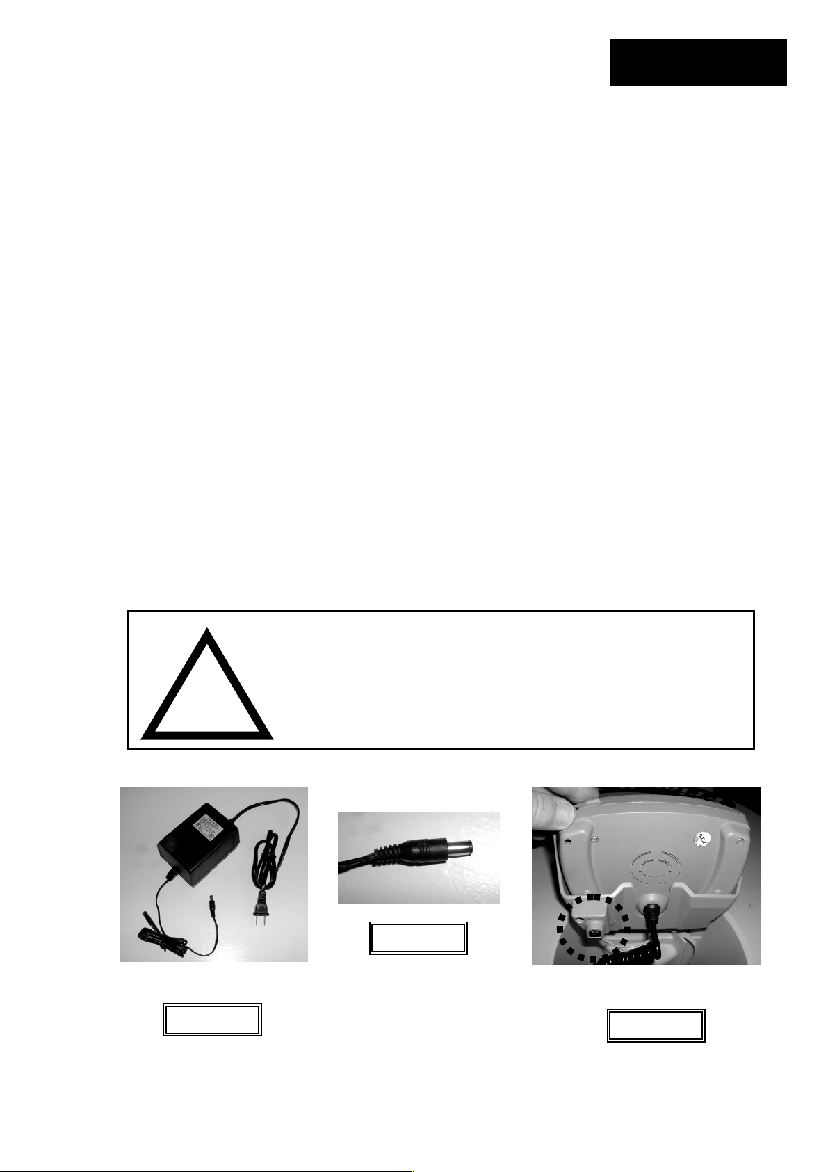
The standard charger (power supply) included with your Robomower will re-charge the Power
Pack from the ‘Recharge Battery’ level in approximately 24 hours, depending on conditions.
Figure 4.1 There is a fast charger available as an accessory. See the accessories available for
your Robomower in Chapter 10.
Connect the output lead of the charger, Figure 4.2, into the charging socket, located under the
Manual Controller holder, Figure 4.3. Connect the other end of the charger to a regular
household receptacle, 120 Volts AC and the charging process will begin (European models utilize
230 volts mains power). Lightly pivot the Manual Controller down, allowing it to rest gently on the
charging cord. DO NOT attempt to force the Manual Controller all the way to the flush position.
The Robomower charger is designed for indoor dry use only. Do not charge the Robomower
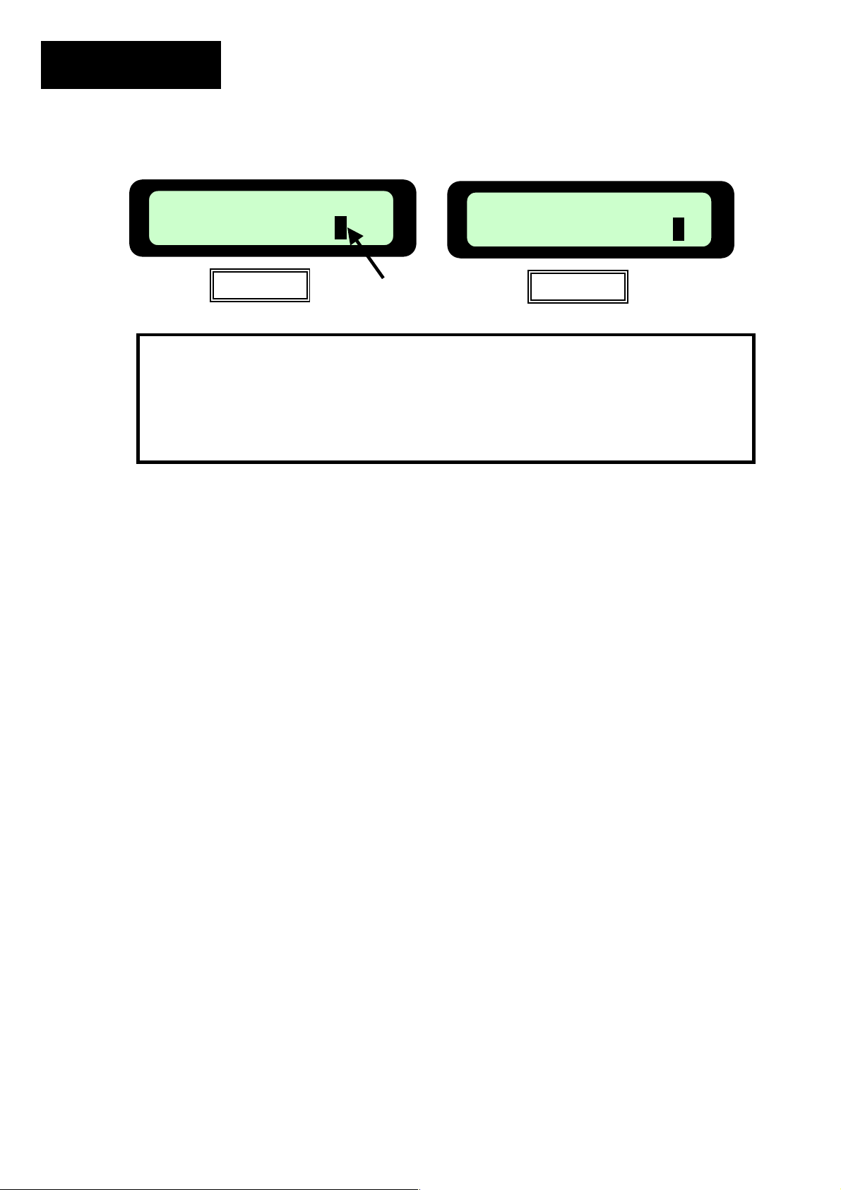
where wet contact is likely. The LCD on the Manual Controller will display the text seen in Figure
4.4 and the battery icon will continually move from empty to full to show the charging. Once the
battery is fully charged, the message will change to that as shown in Figure 4.5, reminding you to
keep it connected to the charger until the next use.
Charging is such an important aspect for assuring good performance and Power Pack life that a
special alert and power management system is incorporated into the mower to remind and alert
you when the proper charging process is not occurring.
WARNING!
Standard charger (power
supply) 120 volt shown
!
Figure 4.1
Shock hazard. Injury or electrocution can occur. The Robomower
charger is designed for indoor use in dry locations only. Never use
the charger or charge the Robomower in areas where extreme
dampness or wet contact is likely. Never use a charger when the
leads are damaged. Use only the recommended charger with your
Robomower.
Charger output lead
Figure 4.2
Standard charger
connector socket
Figure 4.3
Page 23
Page 26
Chapter 4
Page 24
The importance of proper charging and maintenance of the
Robomower Power Pack cannot be stressed enough. Failure
to follow the recommended charging procedures will result in
poor performance of the Robomower and shorten the life of
Charging
Figure 4.4
Battery Icon
the Power Pack.
Ready
Keep Charging
Figure 4.5
4.3 Off-season storage
The Power Pack is best to stay connected to the charger at all times of non-use. The charging
system is designed to operate continuously without a problem and will not damage the Power
Pack. The only exception to this rule concerns extremely cold temperatures. If you store your
Robomower in an area where the temperatures can reach –4F (-20 C) then follow these steps;
1) fully charge the Power Pack for each Robomower you own
2) store them in a dry area where the temperature will not fall below 0 degrees F (-18 C).
The Robomower should always
be connected to the charger
when not in operation
Page 27
Chapter 5
g
p
Manual Operation
5.1 Driving and Navigating
The Robomower is equipped with a Manual Controller that allows you to easily drive it. Using
your thumb or index finger of your right hand, gently press the navigator button in the direction
you want to drive. The button is omni-directional, allowing for slight turns as well as sharp turns,
all the way to a complete circle.
WARNING!
!
5.2 Manual Mowing
You have the ability to manually activate the blades on the Robomower in order to trim small
areas. After the blades are activated you may drive the mower using the navigator button and
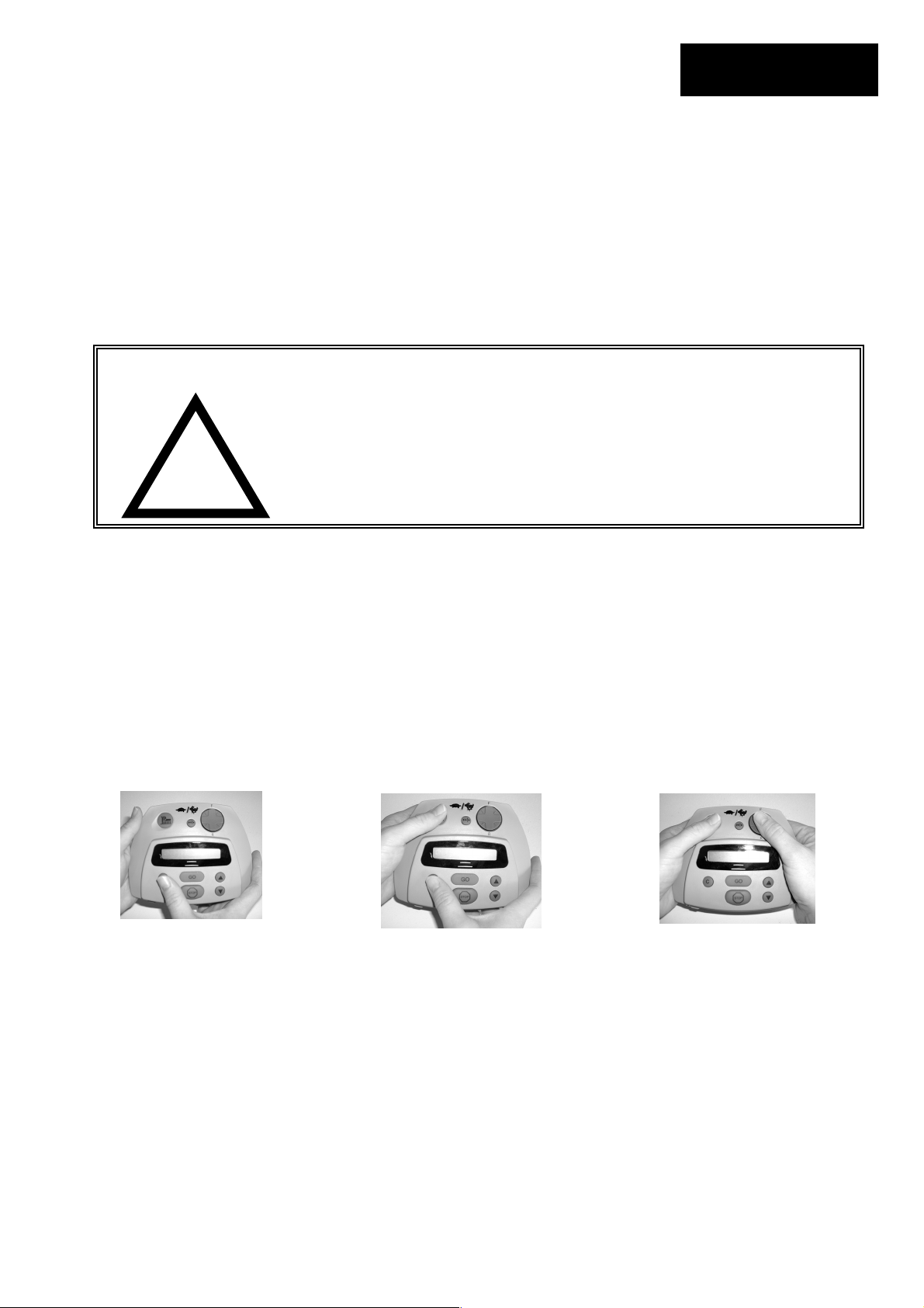
you may cut in any direction the navigator button will operate. The manual mowing operation on
the Manual Controller is a two-step OPC (Operator Presence Control) type system for safe use.
At any time the blades have been stopped, it will require the OPC activation process to be
repeated. During manual mowing operation, activation to any bumper sensor will shut down the
blades, requiring the blade activation process to be repeated.
Step 1
Serious injury can occur. Always wear appropriate footwear when driving
and using the Robomower in the manual mode. Keep a safe distance from
the mower when operating it manually. Note that the reverse driving
direction is from the point of view standing at the rear of the mower. Always
look behind you when using the reverse direction drive. Do not operate the
mower in areas not suitable for manual operation or on slopes where a sure
footing is not possible. Cut across slopes for safety. Do not drive the
mower with persons sitting on it and do not manually operate within 10 feet
(3 m) of other persons or pets.
Step 2
Step 3
Chapter 5
Page 25
Using right thumb, press and hold
‘C’ button
While holding the ‘C’ button,
press the ‘Mow’ button with
your left thumb. The blades
Release the ‘C’ button. Maintain
pressure on the ‘Mow’ button with your
left thumb. Navigate and drive the
mower using your right thumb on the
‘Navi
ator’
ad.
Page 28
Chapter 6
Page 26
Chapter 6
Operator Settings and Advanced
Features
6.1 User Options
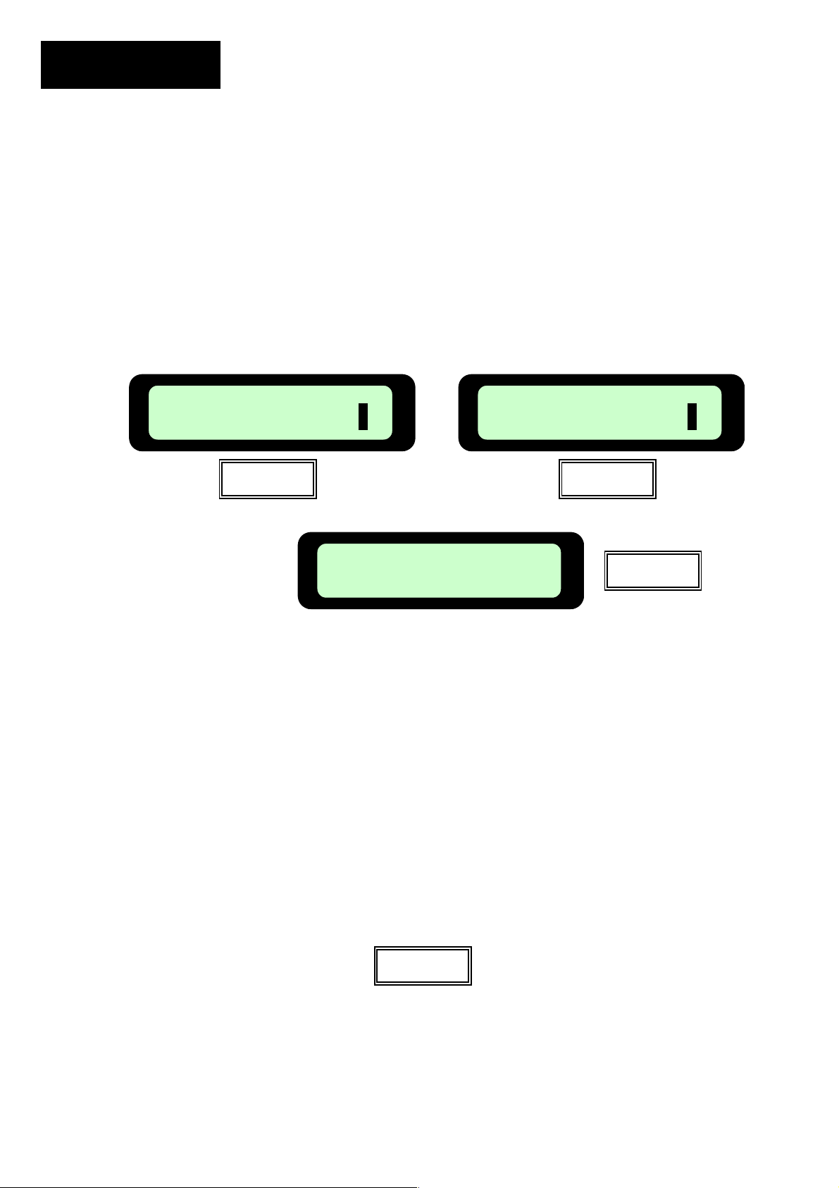
Lifting the Manual Controller from its holder will change the text display on the LCD to the manual
operating menu, as seen in Figure 6.1. Use the arrow keys to view options. Pressing ‘GO’ once
will take you to the next screen, User Preferences’. Figure 6.2. Press ‘GO’ to view the menu of
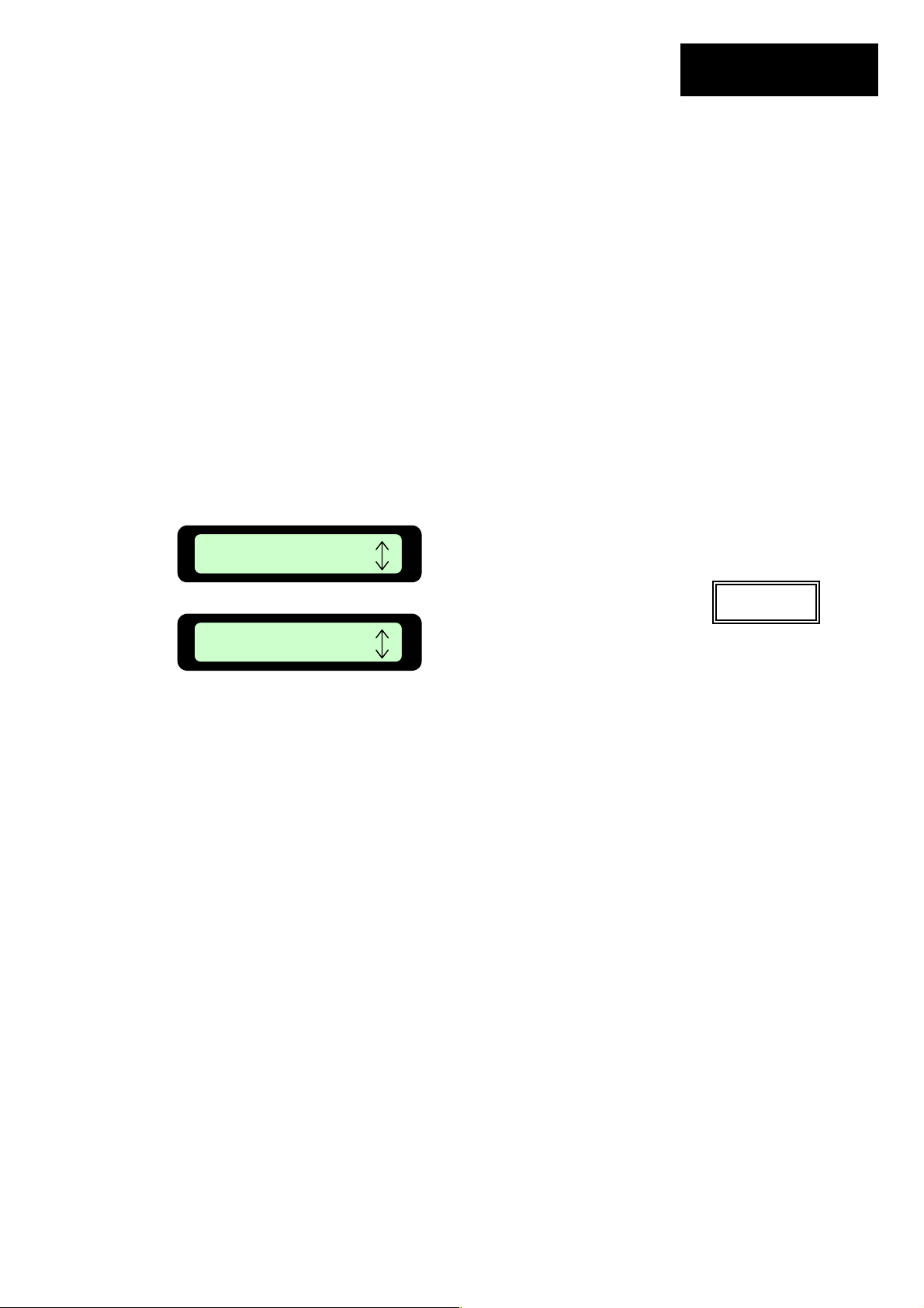
user preferences, beginning with ‘Sound’, Figure 6.3. Using the ‘Up Down ’ arrow keys will
allow you to scroll through these menu items. Pressing ‘GO’ will take you to these various
preferences. Figure 6.4
The ‘GO’ button is used as a means to select or confirm different menu options or settings. By
pressing the ‘GO’ button, it will generally select or confirm what is shown on the second line of
the LCD text message. There are several settings for which the operator can make changes to
or features to enable/disable. Pressing the ‘C’ button at any time during the menu selection
process will bring you back to the main menu. The following menu options are available to the
user and may be changed as desired; (not all options are available on all models)
User Options User Preferences
1) Child Guard 1) Sound
2) Safety Test 2) Mowing
3) Service (not accessible to user) 3) Language
Manual
User Options
Figure 6.1 Figure 6.2
Sound On
Press GO
4) Work Time
5) Learn Edge –(visible only when in Manual
Controller holder and pivoted to the closed
position) (RL800 US & RL850 Europe)
6) Set Default Edge
7) Wide Scan (RL800 US & RL850 Europe)
8) Anti-Theft (RL800 US & RL850 Europe)
Figure 6.4
User Preferences
Press GO
Figure 6.3
Page 29
6.2 Sound
Allows user to shut off non-safety related operating sounds.
6.3 Mowing
Allows user to turn blade operation off, preventing blade operation during automatic operation
and manual mowing.
6.4 Language
Allows the user the option of viewing the LCD text in several different language versions.
6.5 Work Time
Allows the user the option of setting the operating time from the ‘MAX’ default setting to times
ranging from 20 minutes up to 2 hours. Figure 6.5 This option is available for up to 4 different
zones, A, B, C or D. Having four different zones can allow you to set operating time for several
different zones that are of varying sizes, not requiring the same operating time for mowing.
Zone A MAX
Press GO
Zone A MAX
GO to Confirm
Scroll to select different operating
times. Times range from: None =
(zero time) to 2 hours to ‘MAX’
Scroll to select
different zones.
Figure 6.5
6.6 Wide Scan
Wide scan provides the Robomower a secondary navigation technique which can prove to be
beneficial in some lawns. Wide scan will increase the distance between subsequent legs of
mowing after each movement off of the perimeter wire. If it appears that the Robomower is
simply driving along the same path back and forth, activate wide scan.
6.7 Learn Edge
This menu option can only be seen when the Manual Controller is in the holder and flush with the
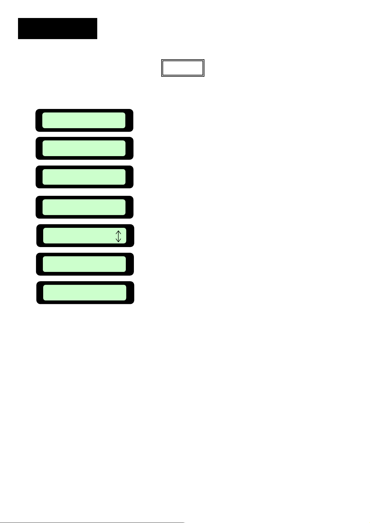
mower top. ‘Learn Edge’ gives you the ability to have the Robomower learn the distance around
the perimeter during edge. Figure 6.6
x Position the Robomower to start edge mowing and place the Manual Controller in the
holder
x Follow the steps described in Figure 6.6 to begin the process
x ‘Learn Edge’ is specific to each zone, so be sure you have selected the correct zone
where you want the edge learned
Chapter 6
Page 27
Page 30
Chapter 6
Page 28
Zone A MAX
Press GO
User Options
Press GO
User Preferences
6.8 Set Default Edge
6.9 Anti-Theft
6.10 Child Guard
Press GO
Learn Edge
Press GO
Learn Zone A
Press GO To Learn
Learning Edge
Press GO to Learn
Learning Edge
Stop to Set
Selecting Default Edge restores the factory default edge distance to the specific zone selected.
The anti-theft system provides the user a disabling function that will prevent anyone from using or
driving the Robomower unless they have the valid code to enter. You will be prompted to enter a
four-digit code of your choice to use as your personal security code. Use the scroll arrows in
order to change each digit position to a different number and then press ‘GO’ to move to the next
digit to select. You will find a place to record your personal security code in Chapter 8 of this
manual. Be sure to record your code for future reference.
Child guard is a feature that when activated will help deter use by young children and other
unauthorized people. It will prevent operation without a proper code, but it is a much simpler
code and is intended as a means to prevent operation to those not familiar with or suitable for
operating the mower. The key sequence to unlock the guard for operation is the same for all
mowers, press the ‘Up’ arrow key and then the ‘C’ key to unlock the controls. One minute of
inactivity will re-lock the keys.
Use the ‘Up’ or ‘Down’ arrow
keys to scroll to the next message
Scrolling up or down will change
the zone, if a time is set for that
Driving around perimeter. Press
Figure 6.6
text.
Press ‘GO’
Press ‘GO’
Press ‘GO’
zone.
Press ‘GO’
the ‘Stop’ button when the
desired distance has been
reached.
Page 31

Chapter 6
6.11 Safety Tests
When selected, the safety test feature will allow you to test the primary safety devices on the
Robomower; 1) front and rear bumpers, 2) lift sensor and 3) the Manual Controller buttons.
Follow the prompts on the menus for testing. Never use the Robomower with a safety device or
feature not properly operating. Never attempt to disable or bypass any safety device or system.
See an authorized Friendly Robotics service facility for repair or information regarding any safety
system or device.
Page 29
Page 32
Chapter 7
Page 30
Chapter 7
Text Messages and Troubleshooting
7.1 Messaging
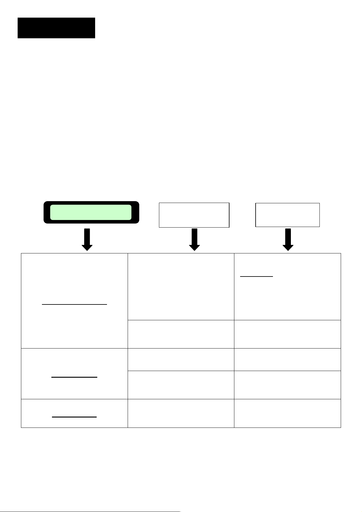
The Robomower is equipped with a sophisticated monitoring system that will notify you in the
form of a text message in the LCD panel when common operational faults occur. In addition, it
will also communicate in text form several messages that are meant as a prompt to the user to
perform a certain function or action. In the event the Robomower has not completed an
anticipated operation and has stopped in the lawn, it will typically display a text message
informing you of the reason it has stopped. If the LCD screen is blank, pressing the ‘GO’ button
one time will wake the mower up and the last fault or message displayed prior to stopping will
now be displayed.
While it is impossible to list every circumstance that will result in a message display, the most
common reasons for a particular message are provided in the following chart. Following this
chart, in Section 7.2, you will also find additional operational and fault issues that may not display
a particular text message in the LCD panel. For issues that cannot be resolved through the use
of these charts please contact your service provider.
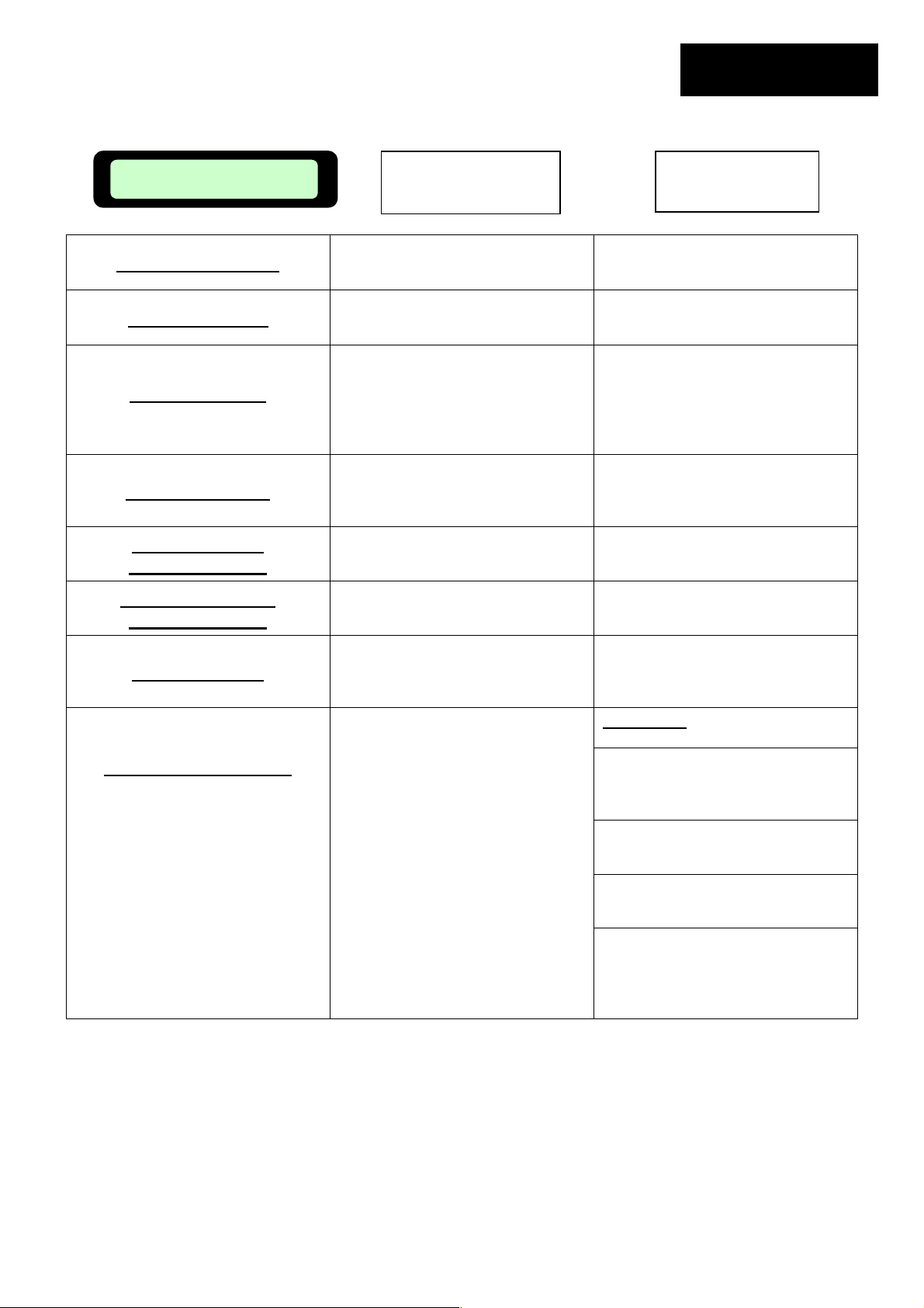
Message Displayed
Probable
Cause/Event
Corrective/User
Action
Check Mow Height
Check Power
Keys Locked
Something is preventing a blade
from rotating freely. Severe grass
accumulation under the mowing
deck; rope or similar object wrapped
around mowing blade; object
jammed under mower preventing
blade from rotating.
Mowing motors have been working
under a severe load. Attempting to
remove more than normal growth of
grass.
Power supply/charger is not plugged
into the main power supply.
No power to receptacle or main
power is shut off.
Child lock feature has been
activated.
CAUTION
before raising mower. Inspect
blades for foreign material or debris.
Clean out accumulated grass
clippings using a wooden stick.
Raise height of blades or have grass
cut to a more reasonable level.
Confirm power supply is plugged into
the main power receptacle.
Check for power to this main
receptacle by plugging in another
appliance. Turn power on to the
Press the Up arrow key and then
press the ‘C’ button. Child lock can
be deactivated under User
– Remove power pack
main receptacle.
Preferences.
Page 33
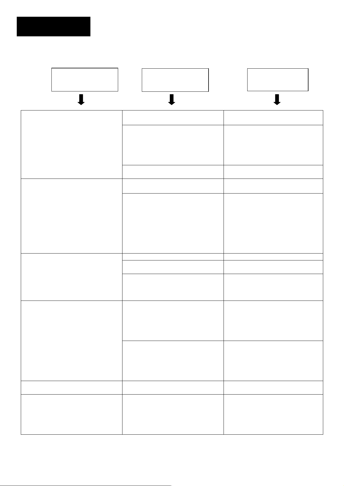
Message Displayed
Restart Elsewhere
Start Elsewhere
Theft Guard On
(RL800 & RL850 only)
Probable
Cause/Event
Calibration failure from interference
in the immediate area.
An unknown fault has occurred and
operator help is required.
The theft guard system is activated.
Chapter 7
Page 31
Corrective/User
Action
Move the Robomower 10-12 feet
(3-4 m) from this spot and attempt
calibration again.
Manually drive the mower away
from this particular area and restart
operation.
Enter the correct 4-digit code.
‘Theft Guard’ can be deactivated
under ‘User Preferences’. Contact
your service provider for assistance
in a lost code situation.
Move From Wire
Drive Overload
Cooling, Wait…
Mowing Overload
Cooling, Wait…
No Wire Signal
Front Wheel Problem
CAUTION – DO NOT
attempt to disable this
safety device in the event
you are unable to isolate
and correct the problem.
Contact your service
provider for repair before
using.
The Robomower is positioned too
close or on top of the perimeter
wire.
The drive motors have been
working under a severe load for too
long of a time.
The mowing motors have been
working under a severe load for too
long of a time.
Perimeter Switch is not turned on or
connected to the zone intended to
mow.
The front wheel has left the ground
for more than 8-10 seconds
Move the Robomower
approximately 6-10 feet (1.5 -3 m)
away from the perimeter wire and
start again.
Wait until the message ‘Drive
Overload – Press GO’ is
displayed
Wait until the message ‘Mowing
Overload – Press GO’ is displayed
Make sure the Perimeter Switch is
connected to the correct zone and
is turned on with the ‘ON’ indicator
flashing.
CAUTION
The Robomower has driven onto a
raised obstacle, raising the front
end. Remove or exclude this object
The Robomower is being used on a
slope too steep for safe mowing.
Exclude this from the mowing area.
High grass is preventing the front
wheel from fully riding on the
ground. Raise the cutting height.
The ground contains large holes or
indentions where the front wheel
can drop into when passing across.
Fill these areas with dirt and level
– Remove Power Pack
before raising mower.
from the mowing area.
off.
Page 34
Chapter 7
Page 32
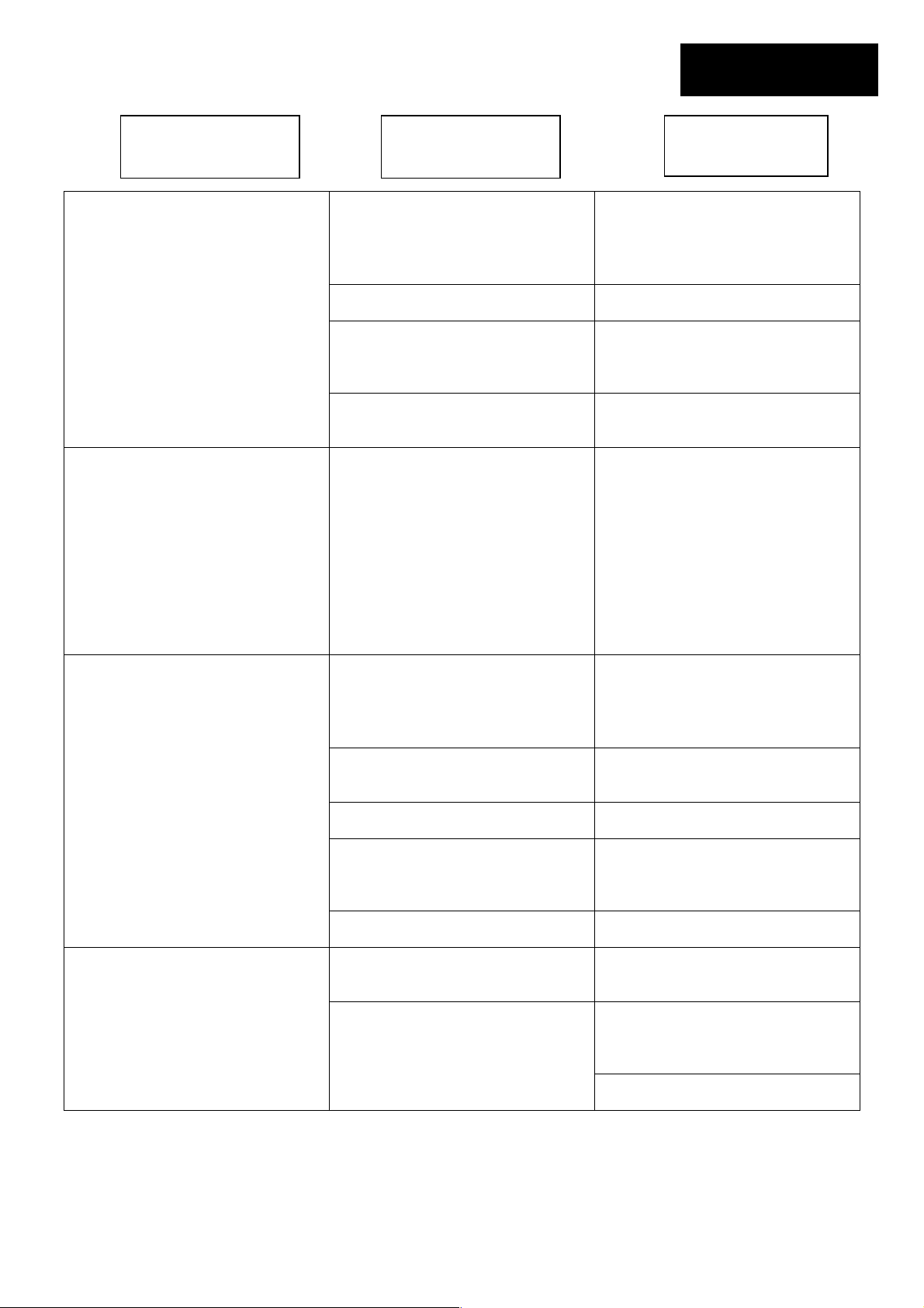
7.2 Other Operational or Fault Problems
Problem
Encountered
Probable
Cause/Event
Corrective/User
Action
‘Cut wire’ indicator flashing on
Perimeter Switch
‘Replace Battery’ indicator flashing
on Perimeter Switch
Perimeter Switch will not activate
when turned on
Robomower will not operate and
nothing will display on the LCD
screen.
Robomower drives but blades will
not mow.
The bumper does not activate when
striking an obstacle.
Wire disconnected from switch
Perimeter wire cut
Poor connections
Weak batteries Install fresh alkaline C-cell batteries
Perimeter wire too long for one zone
Batteries are completely discharged. Install fresh alkaline C-cell batteries
Batteries installed with wrong polarity
position.
Perimeter Switch not installed
vertically and exposed to water/rain.
Mower is in deep sleep.
Power Pack has been discharged
from lack of charge maintenance.
‘Mowing ‘has been turned to off.
The obstacle is less than 6 inches
(15 cm) in height, is not rigid enough
or is positioned at an angle relative
to the ground preventing square
contact with the outermost surface of
the bumper.
Confirm wire is plugged in and wire
leads are firmly attached
Walk along perimeter, including
islands and obstacles excluded with
the perimeter wire and look for
obvious cuts or breaks in the wire.
Repair with Robomower wire splice
connectors.
Check and repair all loose/poor or
corroded connections
A maximum perimeter wire length of
1000 feet (300 m) is recommended.
Areas requiring longer lengths
should be broken into separate
zones. If the ‘Cut Wire’ indicator
flashes once when the Perimeter
Switch is activated, this confirms a
length too long for a single
perimeter zone.
Verify correct placement of
batteries.
Water/moisture protection of the
Perimeter Switch can only be
insured when mounted vertically.
Replace Perimeter Switch.
If not connected to the charger at all
times when not in use, the
Robomower will conserve power by
entering into a deep sleep mode.
Lift Power Pack from mower and re-
insert it after 10 seconds.
It is required for the charger to
remain connected to the
Robomower when not in use.
Failure to do so can cause
permanent Power Pack damage.
Contact your service provider.
Change back on under ‘User
Preferences’
Remove the obstacle or exclude it
from the cutting area with the
perimeter wire.
Page 35
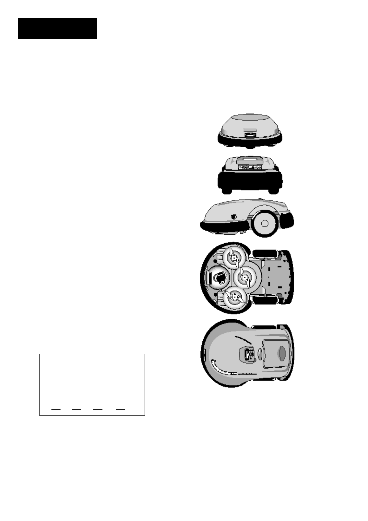
Problem
Encountered
Short run time, operates less time
than normal
LCD display is in a foreign
language.
Large patches of uncut grass
remain after Robomower has
completed mowing.
Robomower does not complete the
edge
Probable
Cause/Event
Power Pack is not fully charged
‘Work Time ‘ for that zone is set to
stop at a pre-determined duration.
Grass is extremely over grown or
very wet. Dull blades.
Power Pack is reaching a normal
end of life state.
The language setting was changed
or not correctly set.
Power Pack is not fully charged for
operation.
‘Work Time’ not sufficient for zone
size.
Power Pack nearing natural end of
life
Grass is extremely overgrown or
very wet.
Power Pack capacity is damaged
from poor maintenance.
Obstacle along path
Peculiar geometry of perimeter
Chapter 7
Page 33
Corrective/User
Action
Connect the charger to the mower
and keep it connected until the
‘Ready – Keep Charging’
message displays in the LCD
screen.
Work time can be changed under
‘User Preferences’
Raise cutting height. Always mow
the grass frequently enough to
prevent over growth. Refrain from
cutting wet grass. Replace blades.
Replace Power Pack. Properly
maintain Power Pack per
instructions.
Remove the Manual Controller and
follow the sequence listed;
1. Press ‘C’ button
2. Press ‘GO’ button twice
3. Press ‘Down’ arrow key
twice
4. Press ‘GO’ button once
5. Using the arrow, scroll to
the correct language
6. Press ‘GO’ to confirm this
selection
Connect the charger to the mower
and keep it connected until the
‘Ready – Keep Charging’
message displays in the LCD
screen.
Increase ‘Work Time’ under ‘User
Preferences’ OR set ‘Work Time’
to ‘MAX’
Replace Power Pack and follow
maintenance instructions in manual.
Raise cutting height. Always mow
the grass frequently enough to
prevent over growth. Refrain from
cutting wet grass.
Replace Power Pack and follow
maintenance instructions in manual.
Watch the full operation of edge
and confirm no obstacles are
present
RL500 & RL550, start edge from
the opposite side of the lawn.
Contact your service provider if this
does not correct the situation.
On RL800 & RL850, perform ‘Learn
Edge’ function
Page 36
Chapter 8
Page 34
Chapter 8
Specifications
Dimensions
35” L x 26” W x 12.5” H (89 x 66.5 x 31.5 cm)
Weight
50 lb. (22.6 Kg) Unit & 28 lb. (12.6 Kg) Power Pack
Power Pack
24 volt, sealed
Normal Ground Speed
20” /sec. (.5 m/ sec)
Cutting Width
21” (56 cm)
Blade Motor RPM
5800 RPM
Noise Level
< 90 db(A)
Equivalent Mowing Power*
5 HP gas walk mulching mower
Front
Rear
Side
Bottom
Theft Guard Code
Fill in the four-digit code you have
selected for the Theft Guard
system as a safe record in the
event you forget the code selected.
* Side by side comparison
Top
Page 37
Chapter 9
Chapter 9
Care and Maintenance
9.1 Mowing Deck
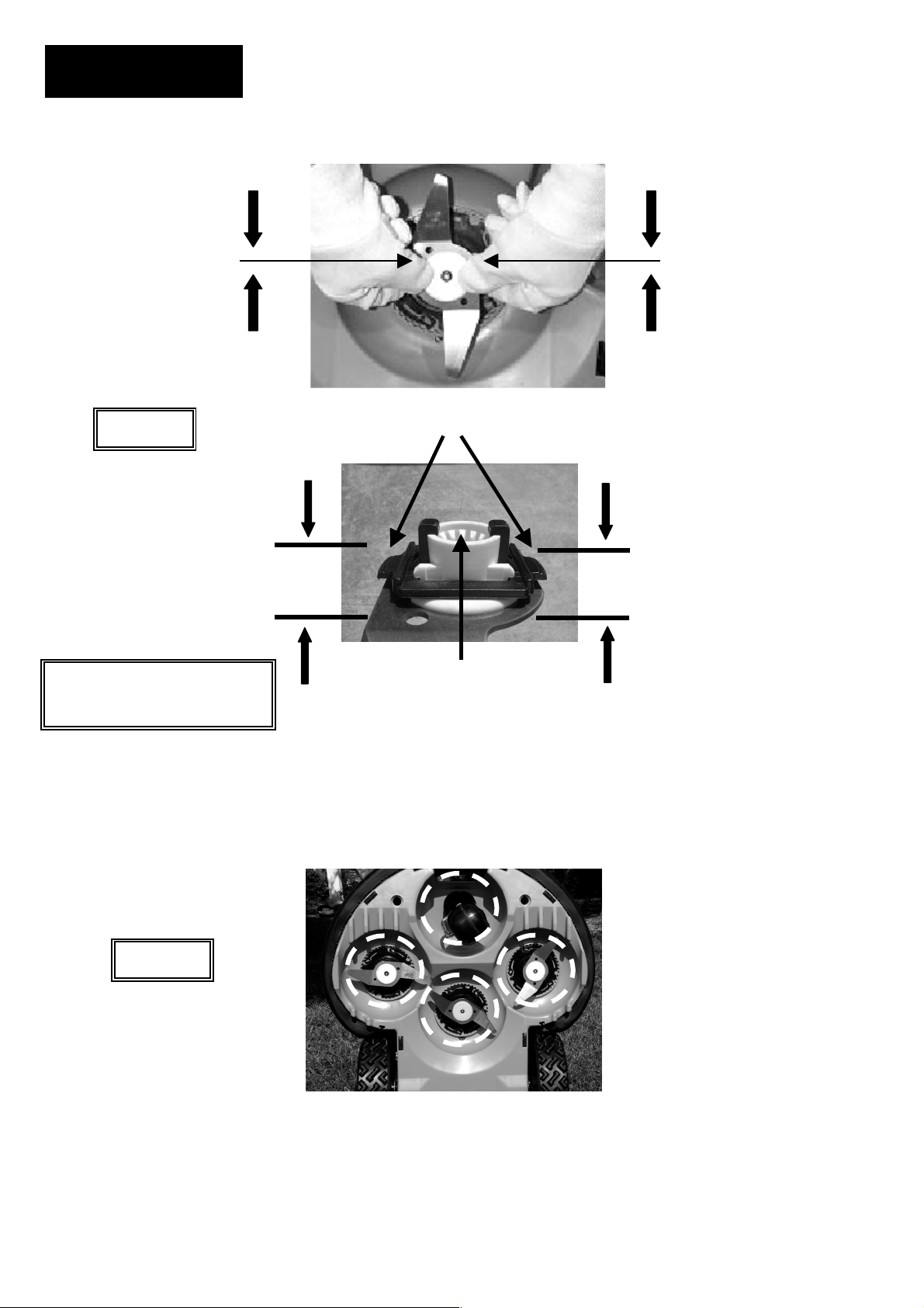
The underside of the mowing deck needs to be inspected, and cleaned if necessary, between
operations. The Robomower is a dedicated mulching mower and because of this can accumulate
clippings under the mowing deck, particularly when mowing wet and damp grass. Figure 9.2
WARNING!
!
Most grass accumulation can be removed using a small wooden stick or similar object. Carefully
scrape the collected grass debris from under the mowing deck. If necessary, remove the blades
to gain better access to the mowing chambers in order to clean them. Do not place the mower
upside down, damage to the Manual Controller can occur. Instead, lean the mower against
another surface to gain access to the mowing deck area.
NEVER use a water hose or other type of liquid sprayer to clean the underside of the mower.
Component damage can occur. Use only a damp or wet cloth to wipe the surface clean after
scraping.
9.2 Blades
The cutting blades of the Robomower should be examined for damage between operations.
Replace any damaged blade found. Only use sharp blades. Replace blades at least once per
season, more often if they have been severely dulled. Machine sharpening is not recommended,
as a good balance cannot be achieved after machine sharpening. See Figure 9.1.
9.3 Outer Housing
Use only a damp cloth and a dry brush to clean the outer surfaces of the Robomower. A light
detergent can be used in a water solution, then soaking and wringing dry the cloth for cleaning.
Never use harsh or abrasive cleaning solutions. Never spray with a garden hose or other type of
liquid spray hose.
9.4 Power Pack
Always follow the maintenance and charging instructions found in Chapter 4 for the Power Pack.
Serious injury can occur. Always remove Power Pack before lifting
mower. Blades are very sharp and can cause severe cuts or lacerations.
Always wear heavy work gloves when working in and around the blades.
Never use a damaged or broken blade. Use only sharp blades.
Page 35
Page 38
Chapter 9
Page 36
Squeeze tabs & pull Squeeze tabs & pull
Figure 9.1
Squeeze here
ALWAYS REMOVE POWER
PACK BEFORE SERVICING
BLADES!
reinstalling the blade, line up the mating splines and push until a firm
click is heard, indicating a proper seating of the blade onto the shaft.
Locking tabs
Squeeze here
Mating spline
To remove blades, squeeze locking tabs on each side of blade
retainer, then pull blade assembly off, away from mower. When
Figure 9.2
Using a wooden stick or similar object, clean accumulated grass
from these areas of the mowing deck. Remove blades if
necessary for better access.
Page 39
Chapter 10
Page 37
Chapter 10
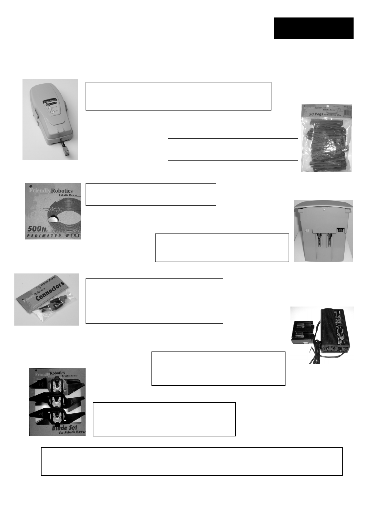
Accessories
Perimeter Switch
Convenience of having a switch for each zone and not moving
one switch from zone to zone.
Perimeter Wire
For larger lawns and additional zones.
Peg Pack (50)
For larger lawns and additional zones.
Power Pack
Convenience of increasing capacity with a
second battery.
Connector Kit
Includes two Perimeter Switch connectors for
additional zones and three silicon filled wire
nuts for repairing or splicing the perimeter
wire.
Fast Charger (External)
Recharges the primary or additional Power
Pack outside of the mower in approximately
4 hours for fast service and use.
Blade Set
Keep a spare blade set on hand. Sharp blades
are important for safety and good cutting
performance.
Accessories can be obtained through your local retailer or visit us on the web at:
www.friendlyrobotics.com
Page 40

Friendly Robotics RL Series Limited Warranty
Friendly Robotics warrants to the original purchaser that the RL series ‘Product’ is free from defects in materials
and workmanship when used under normal residential* purposes for a period of 24 months, 12 months for the
batteries, beginning from the date of purchase. Product accessories, including replacement batteries, are
warranted for a period of ninety days from the date of purchase. This warranty provides for the cost of parts and
labor to repair covered defects when performed by an authorized Friendly Robotics service and warranty facility.
A valid proof of purchase is required for warranty repairs. The limited warranty does not cover transportation
costs of any kind. The owner bears all responsibility for transportation costs to an authorized Friendly Robotics
service and warranty facility.
*Normal residential purposes is defined as use of the product on the same lot as your primary home. Use at more
than one location is considered commercial use, and this warranty would not apply.
Items and Conditions Not Covered
This express warranty does not cover the following:
x Cost of regular maintenance service parts or procedures, such as blades or blade sharpening.
x Any product or part that has been altered, misused, abused or requires replacement or repair due to
accidents or lack of proper maintenance.
x Normal wear and tear, including fading of paint or plastic parts.
x Cost of installation or reinstallation, removal of installation or any costs or damages associated with improper
installation or use of product.
x Any product that has been opened, repaired, modified or altered by anyone other than a Friendly Robotics
authorized repair facility.
x Repairs necessary due to improper battery care and/or improper charging process such as charging in wet
conditions, electrical supply irregularities, or failure to properly prepare the mower or battery prior to any
period of non-use.
x Repairs necessary due to water damage, other than incidental rain exposure, repairs due to lighting or other
acts of God.
Instructions for Obtaining Warranty Service
Should you feel your Friendly Robotics product contains a defect in materials or workmanship, contact the retailer
who sold you the product.
Owner Responsibilities
You must maintain and care for your Friendly Robotics product by following the maintenance and care
procedures described in the owner/operator manual. Routine maintenance, whether performed by a service
provider or by you, is at your expense.
General Conditions
Repair by an authorized Friendly Robotics service and warranty repair facility is your sole remedy under this
warranty. There is no other express or implied warranty. All implied warranties of merchantability and fitness for
use are limited to the duration of this express warranty. Friendly Robotics is not liable for indirect, incidental or
consequential damages in connection with the use of the Friendly Robotics Product covered by this warranty,
including any cost or expense of providing substitute equipment or service during reasonable periods of
malfunction or non-use pending completion of repairs under this warranty. Some states do not allow exclusions of
incidental or consequential damages, or limitations on how long an implied warranty lasts, so the above exclusion
and limitations may not apply to you. This warranty gives you specific legal rights, and you may also have other
rights which vary from state to state.
Always follow the safety instructions
specified in the Operating Manual.
Page 41

Page 42

Have a question?
Please contact your local dealer
Or call us at:
01964 503817
 Loading...