

Page 1
MINI2440 User Manual
Page 2

1. OVERVIEW.........................................................................................................................................................5
1.1 DESCRIPTION...................................................................................................................................................5
1.1.1 Topview of Board....................................................................................................................................6
1.1.2 Hardware Features ................................................................................................................................6
1.1.3 Material list on CD................................................................................................................................8
1.2 HARDWARE RESOURCE....................................................................................................................................8
1.2.1 Memory Map and Chip Selection...........................................................................................................8
1.2.2 Jumpers..................................................................................................................................................9
1.2.3 Interfaces..............................................................................................................................................10
1.3 LINUX FEATURES...........................................................................................................................................10
1.4 WINDOWS CE FEATURES ...............................................................................................................................11
2. HOW TO USE MINI2440..................................................................................................................................12
2.1 HARDWARE SETUP.........................................................................................................................................12
2.1.1 Boot Mode............................................................................................................................................12
2.1.2 External connection .............................................................................................................................12
2.1.3 Hypterminal Setup................................................................................................................................13
2.2 BIOS FUNCTION............................................................................................................................................13
2.2.1 Enter BIOS...........................................................................................................................................13
2.2.2 Install USB Driver ...............................................................................................................................14
2.2.3 Main Menu Function............................................................................................................................15
2.2.4 Partition Sub Menu Function...............................................................................................................17
2.2.5 Linux Parameter Setup.........................................................................................................................20
2.3 TEST PROGRAM WITHOUT OS........................................................................................................................22
2.3.1 Download 2440test ..............................................................................................................................22
2.3.2 Hardware Test......................................................................................................................................23
2.4 LINUX FUNCTION...........................................................................................................................................29
2.4.1 MP3 Play .............................................................................................................................................29
2.4.2 Stop a Program ....................................................................................................................................29
2.4.3 Use U-Disk and Mobile Harddisk........................................................................................................29
2.4.4 Use SD Card........................................................................................................................................31
2.4.5 Transfer file with PC............................................................................................................................31
2.4.6 LED Control.........................................................................................................................................31
2.4.7 Button Test............................................................................................................................................32
2.4.8 Serial 2 and 3 Test................................................................................................................................32
2.4.9 Beeper test............................................................................................................................................33
2.4.10 LCD Backlight....................................................................................................................................34
2.4.11 I2C Test...............................................................................................................................................34
2.4.12 Telnet..................................................................................................................................................35
2.4.13 Telnetd................................................................................................................................................36
2.4.14 How to modify MAC address..............................................................................................................36
Page 3

2.4.15 Ftpd....................................................................................................................................................38
2.4.16 Remote LED control...........................................................................................................................39
2.4.17 NFS ....................................................................................................................................................39
2.4.18 RTC Setup ..........................................................................................................................................40
2.4.19 Non-valitaile Data in Flash................................................................................................................40
2.4.20 Automatic Script When Power Up......................................................................................................40
2.4.21 How to do Screen Shoot.....................................................................................................................40
2.5 WINDOWS CE FUNCTION...............................................................................................................................41
2.5.1 USB Keyboard Simulation....................................................................................................................41
2.5.2 LED Test...............................................................................................................................................42
2.5.3 Screen Rotation....................................................................................................................................43
2.5.4 COM Debugger....................................................................................................................................44
2.5.5 Use U-Disk...........................................................................................................................................44
2.5.6 Use SD/MMC Card..............................................................................................................................45
2.5.7 Use Windows Media Player .................................................................................................................46
2.5.8 Use Super Player .................................................................................................................................46
2.5.9 Ethernet Test.........................................................................................................................................47
2.5.10 Telnet..................................................................................................................................................47
2.5.11 Ftp ......................................................................................................................................................48
2.5.12 Web Server..........................................................................................................................................49
2.5.13 Touch Screen Calibration...................................................................................................................49
2.5.14 ActiveSync with PC............................................................................................................................51
2.5.15 Wireless Lan Card Test.......................................................................................................................51
2.6 H-JTAG INSTALLATION FOR NOR FLASH PROGRAMMING..............................................................................53
3. OS INSTALLATION.........................................................................................................................................56
3.1 BACKUP AND RESTORE SYSTEM ....................................................................................................................56
3.2 INSTALL LINUX..............................................................................................................................................60
3.2.1 Nand Flash Make Partition..................................................................................................................61
3.2.2 BIOS Recovery.....................................................................................................................................61
3.2.3 Install Kernel........................................................................................................................................63
3.2.4 Install yaffs...........................................................................................................................................64
3.2.5 Start OS................................................................................................................................................65
3.3 INSTALL WINCE .............................................................................................................................................65
3.3.1 Nand Flash Make Partition..................................................................................................................65
3.3.2 BIOS Recovery.....................................................................................................................................66
3.3.3 Install EBoot ........................................................................................................................................67
3.3.4 Install Kernel........................................................................................................................................68
APPENDIX: OS INSTALLATION BY COMMAND LINE ..............................................................................70
1. HOW TO ENTER COMMAND LINE MODE ............................................................................................................70
1.1 From BIOS main menu............................................................................................................................70
1.2 From Nand Flash boot............................................................................................................................70
2. LINUX INSTALLATION ......................................................................................................................................71
2.1 Nand Flash Make Partition.....................................................................................................................71
Page 4

2.2 BIOS Recovery........................................................................................................................................72
2.3 Install Linux............................................................................................................................................ 73
2.4 Install yaffs..............................................................................................................................................74
2.5 Start OS...................................................................................................................................................75
3. WINCE INSTALLATION......................................................................................................................................75
3.1 Nand Flash Make Partition.....................................................................................................................75
3.2 BIOS Recovery........................................................................................................................................76
3.3 Install EBoot ...........................................................................................................................................77
3.4 Install Kernel ..........................................................................................................................................78
Page 5

1. Overview
1.1 Description
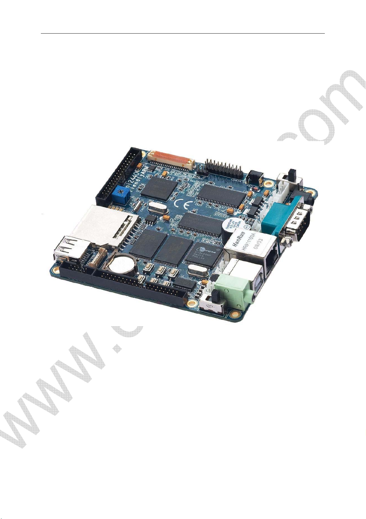
MINI2440 is a single board computer based on Samsung S3C2440 microprocessor.
Page 6
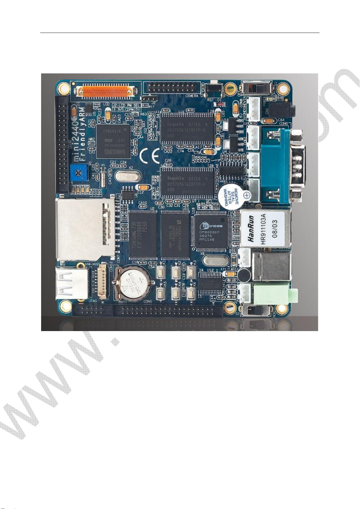
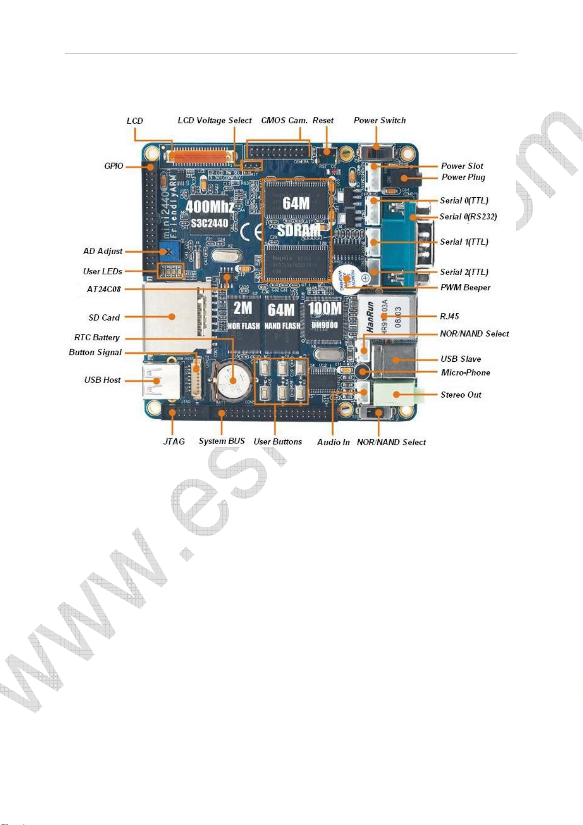
1.1.1 Topview of Board
1.1.2 Hardware Features
CPU
- Samsung S3C2440A,400MHz,Max. 533Mhz
SDRAM
- 64M SDRAM
- 32bit DataBus
- SDRAM Clock 100MHz
Page 7

Flash
- 64M Nand Flash,
- 2M Nor Flash,BIOS installed
LCD
- 4 wire resistive touch screen interface
- Up to 4096 color STN,3.5 inches to12.1 inches, up to 1024x768 pixels
- Up to 64K color TFT,3.5 inches to 12.1 inches, up to1024x768 pixels
Interface and Resource
- 1 10/100M Ethernet RJ-45(DM9000)
- 3 Serial Port
- 1 USB Host
- 1 USB Slave Type B
- 1 SD Card Interface
- 1 Stereo Audio out,1 Micro In;
- 1 20-Pin JTAG
- 4 USER LEDs
- 6 USER buttons
- 1 PWM Beeper
- 1 POT can be used for A/D converter adjust
- 1 AT24C08 for I2C test
- 1 20-Pin Camera Interface
- 1 Battery for RTC
- Power In(5V), with switch and lamp
Oscillator Frequency
- 12MHz
RTC
- Internal
Expand Interface
- 1 34-Pin 2.0mm GPIO
- 1 40-Pin 2.0mm System Bus
Dimension
- 100 x 100(mm)
OS Support
- Linux 2.6.29
- Windows CE.Net 5.0
Page 8

1.1.3 Material list on CD
(1) H-JTAG Debugger
(2) Windows Flash Programmer SJF2440
(3) Linux Nand Flash Programmer Jflash-2440(source code included)
(4) Serial tool CRT, dnw
(5) Bitmap to C Language transfer tool
(6) USB Driver(WindowXP/2000)
(7) vivi source code(linux bootloader)
(8) LED test program(ADS1.20 project)
(9) 2440test program(ADS1.20 project), include :
key test, RTC test, ADC test, IIS Audio play(wav), IIS Audio record,
touch screen test, I2C test, Samsung 3.5"LCD, 640x480 TFT test
(10) WindowsCE BSP and sample project file
(11) Linux tool and kernel source code :
- arm-linux-gcc-4.3.2 with EABI
- yaffs2 file system image maker – mkyaffs2image
- linux-2.6.29 for MINI2440 kernel source code(include DM9000,LCD driver, Audio,
Touch screen, YAFFS Source code, SD Card, RTC, Expand serial driver,
USB Camera,USB Mouse and Keyboard, U-Disk)
(12) Qtopia 2.2.0 source code,web browser source code
(13) Schematic(Protel99SE/PDF)
(14) User Manual(English)
1.2 Hardware Resource
1.2.1 Memory Map and Chip Selection
S3C2440 support 2 boot mode: Nand Flash boot and Nor Falsh boot. Memory map and chip
selection is different based on different boot mode:
Page 9
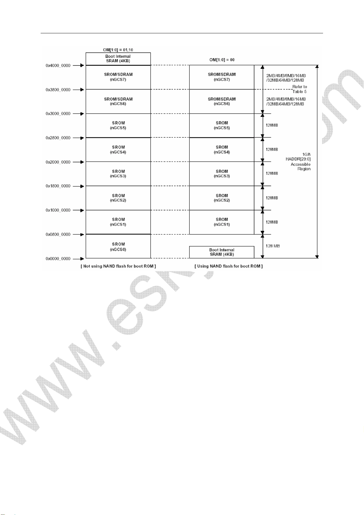
For Nand Flash Boot, 4k Bytes BootSram mapped to nGCS0 space
For Nor Flash Boot, Nor Flash mapped to nGCS0 space
SDRAM address space: 0x30000000-0x34000000
1.2.2 Jumpers
MINI2440 has 1 Jumper, J2:
(1) J2 Power voltage selection for LCD module
NEC LCD 3.5(240x320) :5V
Page 10
1.2.3 Interfaces
1.3 Linux Features
Version
- Linux 2.6.29
File system
- yaffs2
- cramfs
- Ext2
- Fat32
- NFS
Basic driver(with source code)
- 3 serial driver
- DM9000 driver
- Audio driver
- RTC driver
- LED driver
- USB Host driver
- LCD driver
Page 11

- Touch screen driver
- USB camera
- USB mouse, keyboard, U-disk, mobile-disk
- SD Card driver
Linux Application
- busybox1.13.3
- Telnet、Ftp、inetd
- boa(web server)
- madplay
- snapshot
- ishow
- ifconfig、ping、route
Embedded GUI(with source code)
- Qt/Embedded 2.2.0
1.4 Windows CE Features
Version
- WindowsCE.net 5.0
Features
- DM9000 driver(source code)
- USB keyboard、USB mouse、USB disk、mobile hard disk
- 3 serial port COM driver
- USB ActiveSync
- Audio driver
- SD driver
- Real time clock
- Registry saving
- Flash save when power lost
- Screen rotating
Default features(Simplify Chinese)
- XP style interface
- Windows Media Player 9.0(mp3, mpeg2, mpeg4, wmv, wav)
- Super Player
- Photo viewer, Note Pad
- IE6
- ftp,telnet,httpd server
- COM debugger
Page 12

2. How to use MINI2440
Linux image was loaded before shipment (supervivi、zImage_n35、root_default.img),Note the
procedures below will be run under Windows。
2.1 Hardware Setup
2.1.1 Boot Mode
Boot mode can be selected by S2, according words on silk screen:
S2 connect to Nor Flash side,system will boot from Nor Flash;
S2 connect to Nand Flash side,system will boot from Nand Flash。
BIOS which pre-loaded in Nor Flash and Nand Flash are the same in shipment. By default, S2 had
been connected to Nand Flash.
2.1.2 External connection
1. Connect serial port 0 to PC COM port by a dummy modem cable
2. Connect Ethernet port to PC by a cross cable
3. Connect DC 5V power adapter to power supply in
4. Connect your phone set to stereo out(Green)
5. Connect your LCD module to LCD connector
6. Connect with PC by a USB cable
Page 13
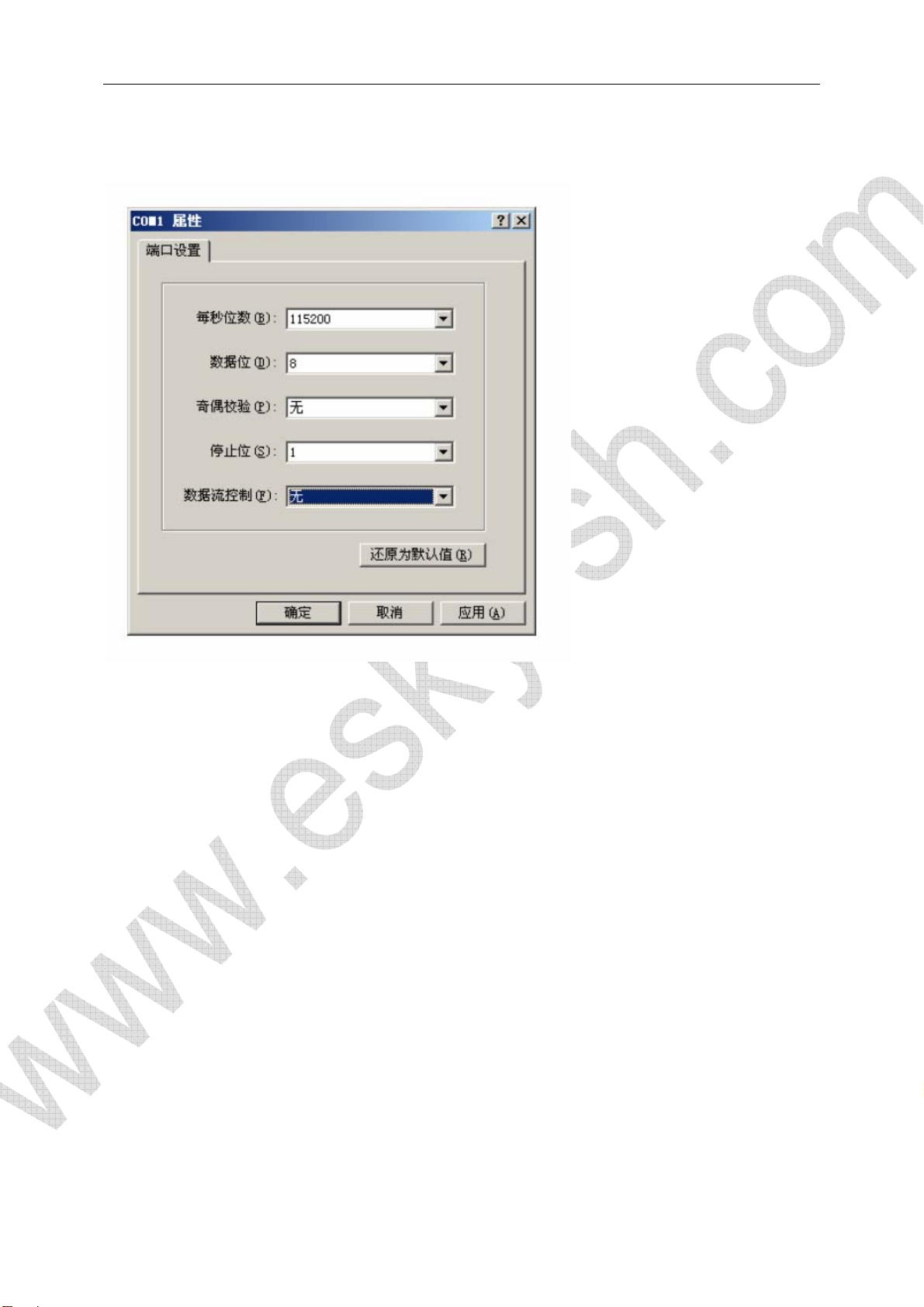
2.1.3 Hypterminal Setup
2.2 BIOS Function
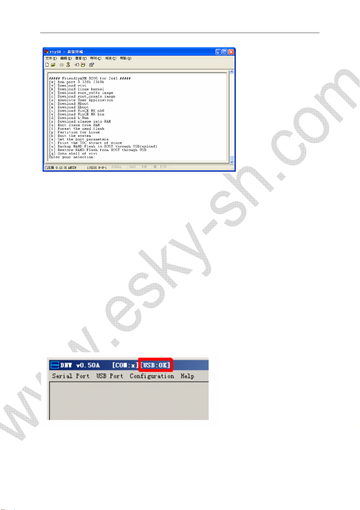
2.2.1 Enter BIOS
Supervivi had been pre-loaded in Nor Flash before shipment. Set S2 to Nor Flash can enter BIOS
main menu after power on:
Page 14
About supervivi:
Supervivi is a bootloader based on Samsung open source vivi. It can be used as a tool to download
and burn OS image to the flash on board. It can also be used to for parameters configuration.
Supervivi download OS image file from PC by USB port.
Supervivi can be installed in either Nor Flash or Nand Flash. When Supervivi is booting from Nand
Flash, user can hold down space bar in Hypterminal when board booting, to force supervivi enter
main menu. Or supervivi will directly boot OS image by default.
Supervivi also has a Download&Run feature which can run user image directly. There is a sample
code 2440test on CD-ROM for this kind application.
2.2.2 Install USB Driver
DNW USB driver for windows is located on CD-ROM \windows tool\usb. Install this driver when
board connected to PC first time. Open DNW, “usb:ok” will indicated on DNW title bar if USB
connection successfully:
USB device list on PC after driver installation
Page 15
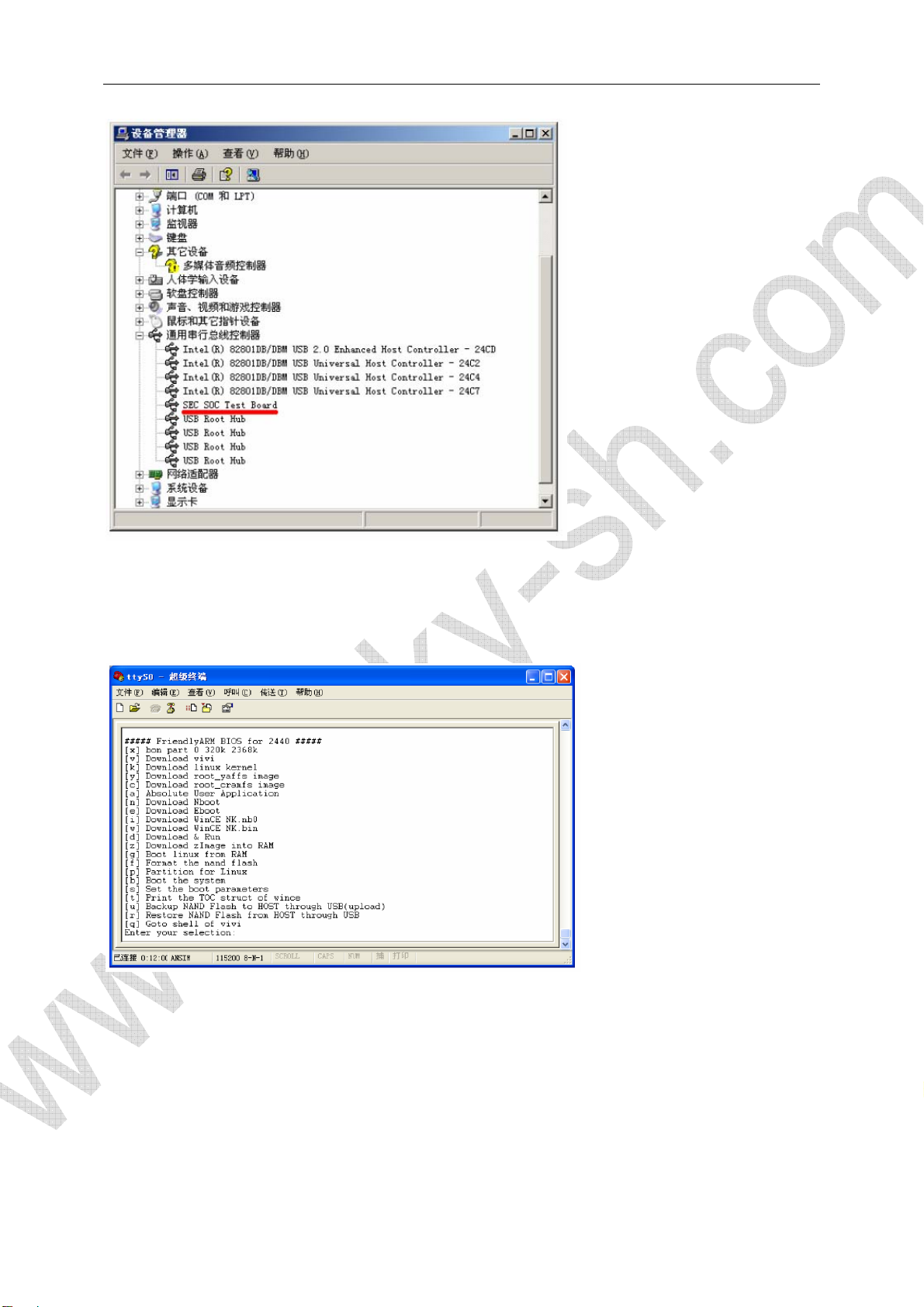
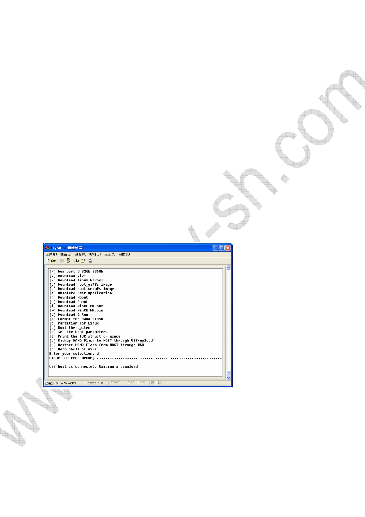
2.2.3 Main Menu Function
Note: DNW is needed for all function related with image downloading through USB connection.
[x]: make default partition on Nand Flash
[v]: download vivi image to vivi partition on Nand Flash
[k]: download linux image to kernel partition on Nand Flash
[y]: download yaffs file system image to root partition on Nand Flash
[c]: download cramfs file system image to root partition on Nand Flash
[a]: download user binary image to Nand Flash, like 2440test, uCos2, U-Boot
[n]: download Nboot image to block0 on Nand Flash
[e]: download Eboot to Eboot partition on Nand Flash
[i]: download NK.nb0 to Nand Flash
Page 16
[w]: download NK.bin to Nand Flash
[d]: download exec image to specific memory address(Address is defined by
DNW|Configuration|Option) and run it. The SDRAM address is 0x30000000 – 0x34000000. The
memory size is 64Mbytes. The user available address space is 0x30000000 – 0x33DE8000.
[z]: download zImage to 0x30008000
[g]: run zImage image in memory, work together with command [z]
[f]: erase Nand Flash. The available address space for Nand Flash is 0x0 – 0x4000000
Start Address End Address
Vivi partition(block0-13) 0x0 0x50000
Linux kernel partition(block14-93) 0x50000 0x250000
File system partition(block94-4095) 0x250000 0x4000000
Whole Chip 0x0 0x4000000
[p]: make partition on Nand Flash for linux. Refer to sub menu function for details
[b]: boot OS
[s]: set linux start up parameters
[t]: display TOC of wince image
[u]: backup the whole content in nand flash and upload it to pc by dnw tool
[r]: restore backup file to nand flash by dnw
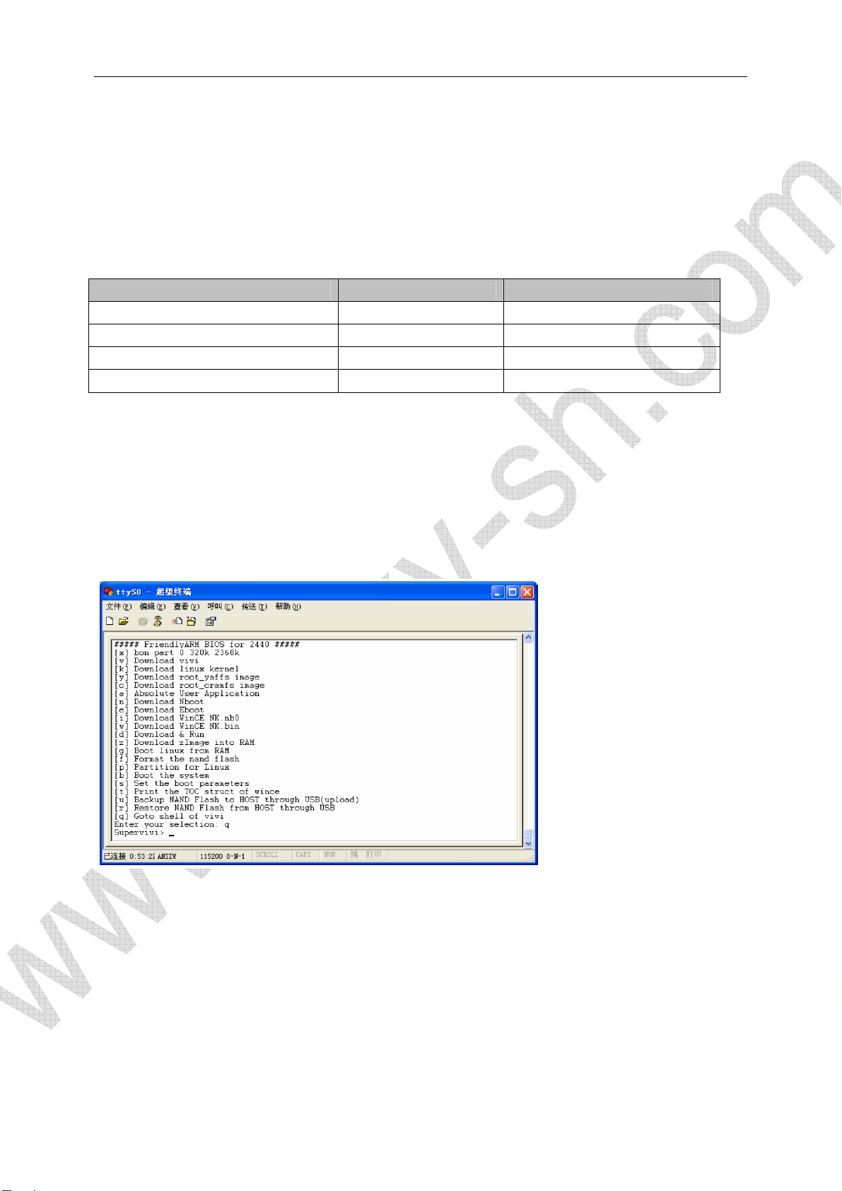
[q]: go to regular command line interface for vivi
Type “menu” to return to main menu for supervivi
Page 17
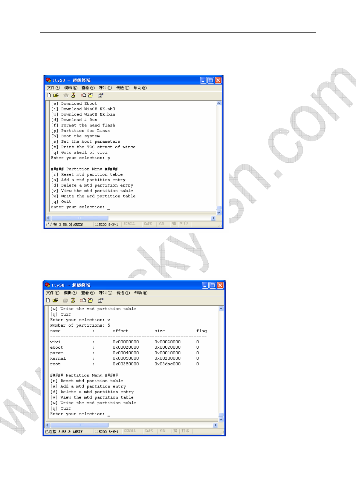
2.2.4 Partition Sub Menu Function
(1) View current partition
Type “v” to view current partition information. If Nand Flash is empty or new, default partition table
will be displayed.
(2) Delete partition
Page 18
Input “d” to delete specific partition. Input “vivi” if you want to delete “vivi” partition:
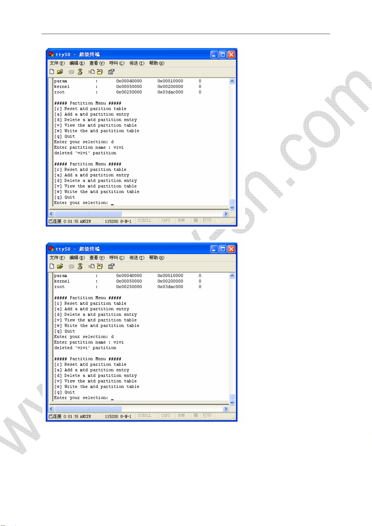
(3) Write Partition
Input “w” to write partition table. Partition modification can only take effect by write command.
Page 19
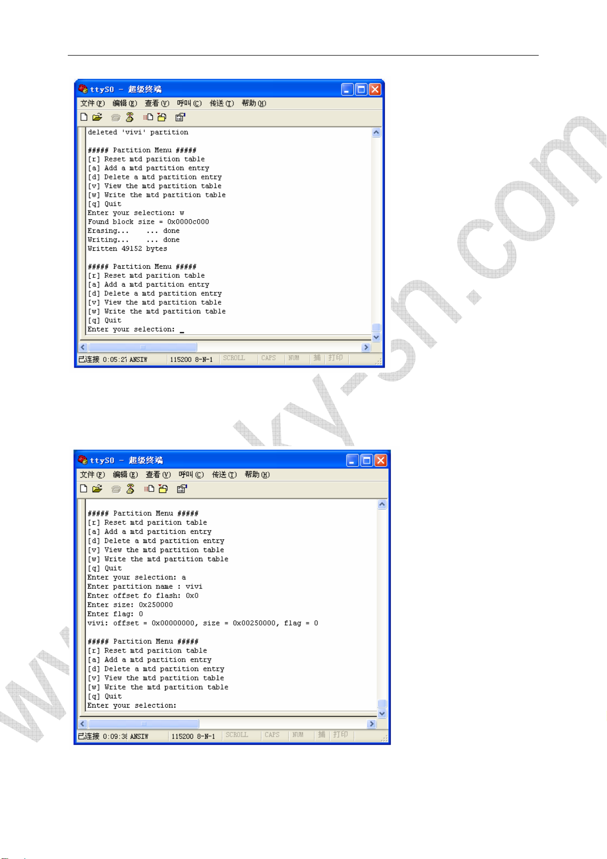
(4) Append Partition
Input “a” to append a new partition. Supervivi will prompt you with some informations for the new
partition like : name, offset, size and flag.
(5) Reset partition table
Page 20
Input “r” to reset partition table with supervivi default parameter. Remember use “w” command to
make your reset operation take effect.
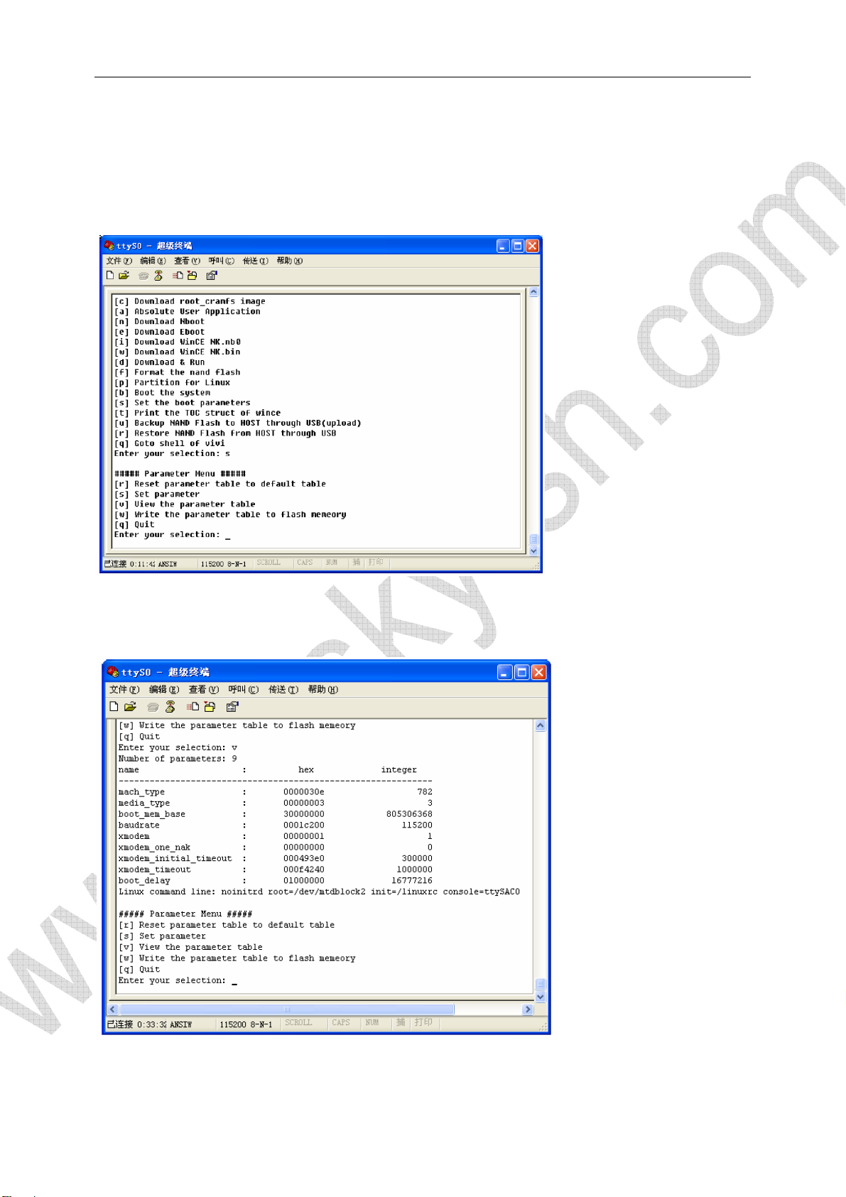
2.2.5 Linux Parameter Setup
(1) View Parameter
Input “v” to view current parameters
(2) Set Parameter
Page 21
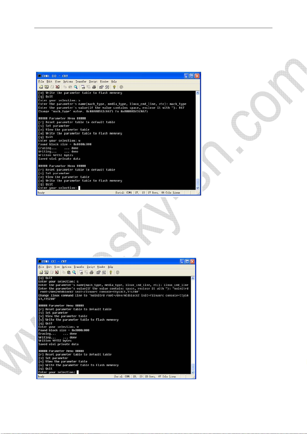
Input “s” to set parameter.
How to set mach_type
The default mach_type is 782. You can change this parameter if you complier your kernel with
MACH_TYPE 867.
How to set linux command line
Linux_cmd_line is a very often used parameter for kernel startup. Here is an example for how to
change default tty terminal from serial 0 to serial 1:
View current parameters:
Linux_cmd_line: noinitrd root=/dev/mtdblock2 init=/linuxrc console=ttySAC0
Input “s”, and then input “linux_cmd_line”, input “return”, and then input:
“noinitrd root=/dev/mtdblock2 init=/linuxrc console=ttySAC1,115200”
After parameter successfully saved, linux will startup and logon from serial 1
Page 22
(3) Save Parameter
Input “w” to save parameters
(4) Recover Parameter
Input “r” to recover default kernel startup parameters
2.3 Test Program without OS
Test program 2440test can be used to test PWM beeper, RTC clock, AD converter, button, touch
screen, LCD, infra, I2C bus, audio in, audio out, SD Card and CMOS Camera.
2.3.1 Download 2440test
Install USB driver on Windows and setup Windows Hypterminal for serial cable connection.
Connect USB cable and launch DNW for 2440test binary image downloading. The USB download
address in DNW should be 0x30000000.
Page 23
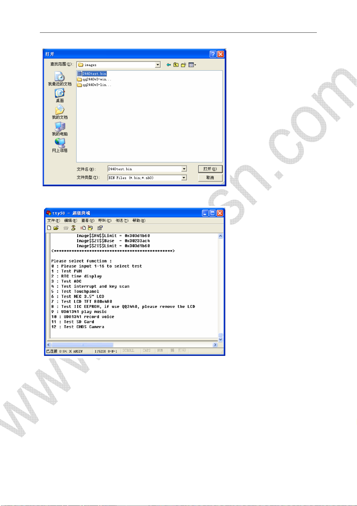
2440test program will automatically run after successfully download:
2.3.2 Hardware Test
(1) Beeper Test
Page 24
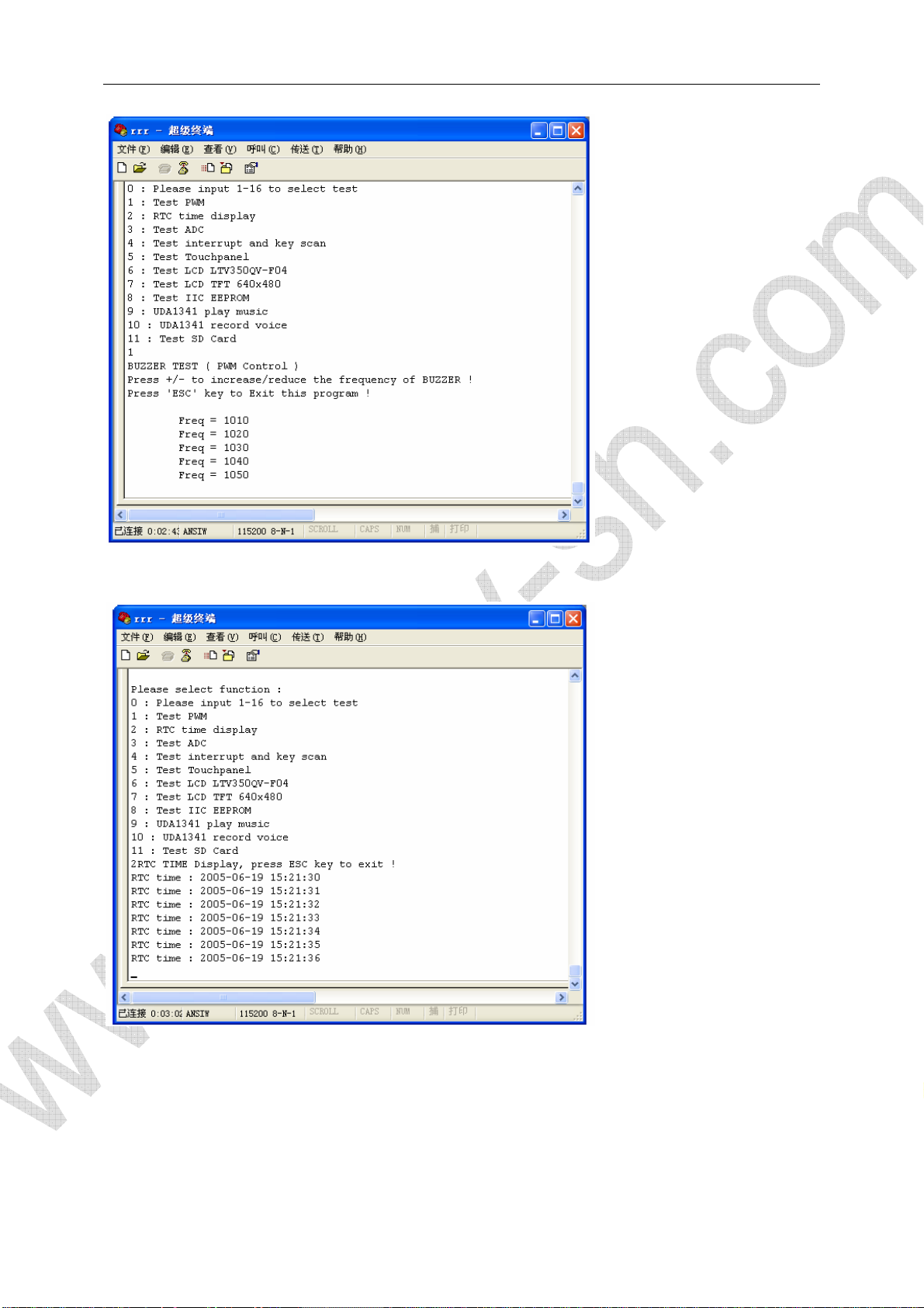
(2) RTC clock test
(3) AD converter test
User can skew W1 on board for this AD converter test.
Page 25

(4) Button Test
(5) Touch Screen Test
Page 26

(6) LCD Test
(8) I2C Test
Page 27

(9) Stereo Out Test
Connect your external phone set or speaker to MINI2440 stereo out socket(Green)
(10) Audio In Test
Page 28

(11) SD Card Test
Page 29

(12) CMOS Camera Test
This function can only be tested when LCD screen connected.
2.4 Linux Function
Linux was pre-loaded as default OS before ship. This default linux image is root_default.img on
CD-ROM. With support by linux, user can test the functionalities of almost all of hardware resources
on the board.
2.4.1 MP3 Play
Madplay is MP3 player under console. It has several play modes and the simplest way to use is:
#madplay your.mp3
Please run “madplay –h” for help of this program.
2.4.2 Stop a Program
Press “Ctrl+c” to stop running of a program. Use “kill” to stop a program running on back ground.
2.4.3 Use U-Disk and Mobile Harddisk
FAT32/VFAT can be automatically recognized by linux kernel after USB mass storage device plug
in.
Page 30

Page 31

2.4.4 Use SD Card
2.4.5 Transfer file with PC
User can transfer(sz/rz) files with PC when he/she login linux by serial console.
2.4.6 LED Control
(1) LED Server
There is a automatically startup script(/etc/rc.d/init.d/leds) after system power on. This script call a
Page 32

server program named as led-player. Led-player will create pipe file at /tmp, so user can change
flash ratio of the leds by sending different parameters to the piple.
#echo 0 0.2 > /tmp/led-control
4 leds will flash as a flow with 0.2 seconds interval
#echo 1 0.2 > /tmp/led-control
4 leds will flash as a accumulating with 0.2 seconds interval
#/etc/rc.d/init.d/leds stop
4 leds will stop flashing
#/etc/rc.d/init.d/leds start
4 leds will start to flash
(2) Separately control of LED
/bin/leds is a separately controller of leds. User need to stop led-player before leds
#/etc/rc.d/init.d/leds stop
[root@fa /]#led
Usage: leds led_no 0|1
Led_no is number of leds(0-3), 0 represent off, 1 represent on
2.4.7 Button Test
Run “buttons” to test buttons on board
2.4.8 Serial 2 and 3 Test
User need an expand board for serial port 2 and serial port 3 test. Set Hypterminal on PC to 115200
Baudrate and no hardware flow control.
#armcomtest –d /dev/tts/1 –o
#armcomtest –d dev/tts/2 –o
Page 33

Result screen from serial port 2 or serial port 3:
2.4.9 Beeper test
Source code location:
Kernel-2.6.13/drivers/char/qq2440_pwm.c
Page 34

2.4.10 LCD Backlight
Source code location:
Kernel-2.6.13/drivers/char/mini2440_backlight.c
[root@FriendlyARM/]#echo 0 >/dev/backlight
[root@FriendlyARM/]#echo 1 >/dev/backlight
2.4.11 I2C Test
Source code location:
Kernel-2.6.13/drivers/i2c/busses/i2c-s3c2410.c
Page 35

2.4.12 Telnet
Page 36

2.4.13 Telnetd
User can telnet to MINI2440 board by root without password.
2.4.14 How to modify MAC address
#ifconfig
Page 37

#ifconfig eth0 down
#ifconfig eth0 hw ether 00:11:AA:BB:CC:DD
#ifconfig eht0 up
#ifconfig
Change MAC address in startup script:
Page 38

2.4.15 Ftpd
Page 39

2.4.16 Remote LED control
Stop web server:
#/etc/rc.d/init.d/httpd stop
Start web server:
#/etc/rc.d/init.d/httpd start
2.4.17 NFS
Assume NFS server is started on 192.168.1.111:
#mount –t nfs –o nolock 192.168.1.111:/opt/FriendlyARM/QQ2440V3/root_nfs /mnt
Unmount command:
#umount /mnt
Page 40

2.4.18 RTC Setup
Use hwclock command to connect linux clock with MINI2440 hardware RTC chip:
(1) date –s 042916352007
(2) hwclock –w
(3) hwclock –s #this command had been put into /etc/init.d/rcS script for automatically run after
power on.
2.4.19 Non-valitaile Data in Flash
Yaffs file system will not lost any data in case system power failure.
2.4.20 Automatic Script When Power Up
Please check with /etc/init.d/rcS
2.4.21 How to do Screen Shoot
#snapshot pic.png
Page 41

2.5 Windows CE Function
2.5.1 USB Keyboard Simulation
Source code location:
SMDK2440\DRIVERS\Userkey
This feature had been compiled in wince kernel by default, so it is available as soon as wince
startup:
K1 - TAB
K2 - UP
K3 - ENTER
K4 - DOWN
K5 - LEFT
K6 - RIGHT
Page 42

Enter “K3” to open “My Device”
2.5.2 LED Test
Double click on “QQ2440 test” to open LED test program
Page 43

2.5.3 Screen Rotation
Source code location:
SMDK2440\DRIVERS\DISPLAY
Page 44

2.5.4 COM Debugger
2.5.5 Use U-Disk
Page 45

2.5.6 Use SD/MMC Card
Page 46

2.5.7 Use Windows Media Player
2.5.8 Use Super Player
Page 47

2.5.9 Ethernet Test
2.5.10 Telnet
A telnet server is configured in WinCE. The default IP address of Wince is 192.168.1.217. No
password needed for telnet logon.
Page 48

2.5.11 Ftp
A ftp server is configured in WinCE. The default IP address of Wince is 192.168.1.217.
Account/password is ftp/ftp
Page 49

2.5.12 Web Server
2.5.13 Touch Screen Calibration
Page 50

Page 51

2.5.14 ActiveSync with PC
2.5.15 Wireless Lan Card Test
A wireless lan card driver is integrated in Wince(VNUWLC41).
Page 52

Page 53

2.6 H-JTAG Installation for Nor Flash Programming
1. Install H-JTAG on your PC
Please refer to www.hjtag.com
2. JTAG port configuration
3. Install init scripts
for detail info of H-JTAG project
Page 54

Copy init script files from CD-ROM to H-JTAG installation directory
Load init script
Page 55

Click OK
4. Target chip detect
Power on target board to detect target CPU
Page 56

3. OS Installation
We need DNW software to install OS images on target CPU board.
3.1 Backup and Restore System
Backup content in Nand Flash
Page 57

Page 58

Page 59

Restore Nand Flash
Page 60

3.2 Install Linux
Linux binary image file is in image/linux folder. Connect MINI2440 board with USB cable and power
on the board to enter supervivi main menu. Watch indicator on DNW title bar to check if USB
connection success:
Major steps for linux installation:
(1) format Nand Flash(make partition)
(2) Install bootloader
(3) Install kernel
(4) Install file system
Page 61

3.2.1 Nand Flash Make Partition
3.2.2 BIOS Recovery
Caution: The operations in section 3.2.1 will erase all data in Nand Flash. Please do not shut off the
power or you will have to re-load supervivi in Nand Flash.
Page 62

And then click USB Port->Transmit to download supervivi image file.
After successfully downloading, BIOS will update this new supervivi image to Nand Flash.
Page 63

3.2.3 Install Kernel
Click DNW USB Port->Transmit to select which kernel image file you want to download. Linux
kernel image will be updated to Nand Flash after successfully downloading.
Page 64

3.2.4 Install yaffs
Click DNW USB Port->Transmit to select which file system image file you want to download. Linux
file system image will be updated to Nand Flash after successfully downloading.
Page 65

3.2.5 Start OS
Please un-plug USB cable after system successfully updated
Input [b] under BIOS or power cycle/reset the board. Supervivi will restart and boot linux
automatically.
3.3 Install Wince
Wince binary image file is on image/wince folder. Connect MINI2440 board with USB cable and
power on the board to enter supervivi main menu. Watch indicator on DNW title bar to check if USB
connection success:
Major steps for Wince installation:
(1) format Nand Flash(make partition)
(2) Install bootloader
(3) Install Eboot
(4) Install Wince
3.3.1 Nand Flash Make Partition
Page 66

3.3.2 BIOS Recovery
Caution: The operations in section 3.3.1 will erase all data in Nand Flash. Please do not shut off the
power or you will have to re-load supervivi in Nand Flash.
And then click USB Port->Transmit to download supervivi image file.
Page 67

After successfully downloading, BIOS will update this new supervivi image to Nand Flash.
3.3.3 Install EBoot
Page 68

3.3.4 Install Kernel
Eboot will prompt user to download wince from USB. Click USB Port->Transmit to select Wince
image file to start download.
Page 69

Eboot will low level format Nand Flash and then convert BinFS. After formatting successfully done,
Eboot will update windows CE image file to Nand Flash. WinCE will automatically start up finally.
Page 70

Appendix: OS Installation by Command
Line
Note: We recommend you use supervivi main menu to update software but we still list command
line commands here for your reference.
1. How to enter command line mode
Supervivi will enter main menu when board is set to Nor Flash boot mode. Select function [q] to
enter command line mode
1.1 From BIOS main menu
1.2 From Nand Flash boot
User can also enter supervivi command line interface when board is booting from Nand Flash.
Connect the board with PC by serial cable and USB cable. Open Windows hypterminal and DNW.
Hold on space bar in Hypterminal. Power on MINI2440 and then you can enter command line
interface:
Page 71

2. Linux Installation
Linux binary image file is on image/linux folder. Connect MINI2440 board with USB cable and power
on the board to enter supervivi command line mode. Watch indicator on DNW title bar to check if
USB connection success:
Major steps for linux installation:
(1) format Nand Flash(make partition)
(2) Install bootloader
(3) Install kernel
(4) Install file system
2.1 Nand Flash Make Partition
Under BIOS: bon part 0 320k 2368k
Description: bon is command to make partition, the command above is to make 3 partition from
Nand Flash address 0:
0-320k: size is 320k
320k-2368k: size is 2M
2368k-64M: size is 62M
Page 72

2.2 BIOS Recovery
Caution: The operations in section 2.1 will erase all data in Nand Flash. Please do not shut off the
power or you will have to re-load supervivi in Nand Flash.
Input: load flash vivi u
And then click USB Port->Transmit to download supervivi image file.
After successfully downloading, BIOS will update this new supervivi image to Nand Flash.
Page 73

Note: User can also use load flash vivi x command to download and update suervivi by xmodem
prototype from hypterminal.
2.3 Install Linux
Input: load flash kernel u
Click DNW USB Port->Transmit to select which kernel image file you want to download. Linux
kernel image will be updated to Nand Flash after successfully downloading.
Page 74

Note: User can also use load flash kernel x command to download and update linux kernel by
xmodem prototype from hypterminal.
2.4 Install yaffs
Input: loadyaffs root u
Click DNW USB Port->Transmit to select which file system image file you want to download. Linux
file system image will be updated to Nand Flash after successfully downloading.
Page 75

2.5 Start OS
Please un-plug USB cable after system successfully updated
Input “boot” under BIOS or power cycle/reset the board. Supervivi will restart and boot linux
automatically.
3. Wince Installation
Wince binary image file is on image/wince folder. Connect MINI2440 board with USB cable and
power on the board to enter supervivi command line mode. Watch indicator on DNW title bar to
check if USB connection success:
Major steps for Wince installation:
(1) format Nand Flash(make partition)
(2) Install bootloader
(3) Install Eboot
(4) Install Wince
3.1 Nand Flash Make Partition
Under BIOS: bon part 0 320k 2368k
Description: bon is command to make partition, the command above is to make 3 partition from
Nand Flash address 0:
Page 76

0-320k: size is 320k
320k-2368k: size is 2M
2368k-64M: size is 62M
3.2 BIOS Recovery
Caution: The operations in section 3.1 will erase all data in Nand Flash. Please do not shut off the
power or you will have to re-load supervivi in Nand Flash.
Input: load flash vivi u
And then click USB Port->Transmit to download supervivi image file.
After successfully downloading, BIOS will update this new supervivi image to Nand Flash.
Page 77

Note: User can also use load flash vivi x command to download and update suervivi by xmodem
prototype from hypterminal.
3.3 Install EBoot
Input: load flash eboot u
Click USB Port->Transmit to select eboot.nb0 to start download. Eboot will be automatically
updated to Nand Flash after successfully downloading.
Note: User can also use load flash eboot x command to download eboot from hypterminal by
xmodem prototype.
Page 78

3.4 Install Kernel
Input : load flash wince u
Eboot will prompt user to download wince from USB. Click USB Port->Transmit to select Wince
image file to start download.
Eboot will low level format Nand Flash and then convert BinFS. After formatting successfully done,
Page 79

Eboot will update windows CE image file to Nand Flash. WinCE will automatically start up finally.
 Loading...