

Friedrich Metal Products WE13B33B-B Service Manual
S08B10A-C
C
C
C
C
C
3B33
6B33
0B33
3B33
W
)
rvi
ce &
ts
ua
®
Thru-the-Wall
Par
Man
l
WallMaster
M
P
r
Powe
72
ool
C
®
an
F
r
e
v
a
S
y
e
on
M
e
od
M
d
e
e
p
S
y
nl
O
an
F
ock
l
C
t
Se
e
m
i
T
t
r
a
t
S
r
e
Tim
Hour
/Off
On
me
i
T
/Hour
p
op
t
m
S
Te
M-Svc-Prts-07 (12-07
W
WS10B10AWS14B10AWS10B30AWS13B30BWS16B30AWE10B33A-B
WE1
WE1
WY1
WY1
B-B
A-B
A-B
A-B

T
ABLE OF
CO
S
W
y
3
................................................................................................................................
4
......................................................................................................................................
.....................................................................................................................................
.
s
0
3
..............................................................................................................................
3
g
..................................................................................................................
0
................................................................................................................................
5
.
arrant
Routine Maintenance
nit Identifi cation
Performance Data
Electrical Data...........................................................................................................................................7
Functional Component Defi nitions........................................................................................................
Electronic Controls
NTENT
Rotary Control
Refrigeration Sequence of Operation
Sealed Refrigeration Repairs
Refrigerant Charging
eneral Troubleshootin
Wiring Diagrams
Parts Diagram .........................................................................................................................................
Parts Lists..........................................................................................................................................7-29
1
12-1
1
14-2
1-2

£
Friedrich Air Conditioning Company
P.O. Box 1540
San Antonio, TX 78295
210.357.4400
www.friedrich.com
WALLMASTER
THRU-THE-WALL AIR CONDITIONERS
LIMITED WARRANTY
FIRST YEAR
ANY PART: If any part supplied by FRIEDRICH fails because of a defect in workmanship or material within twelve months from
date of original purchase, FRIEDRICH will repair the product at no charge, provided room air conditioner is reasonably accessible
for service. Any additional labor cost for removing inaccessible units and/or charges for mileage related to travel by a Service
Agency that exceeds 25 miles one way will be the responsibility of the owner. This remedy is expressly agreed to be the exclusive
remedy within twelve months from the date of the original purchase.
SEALED REFRIGERANT SYSTEM: If the Sealed Refrigeration System (defined for this purpose as the compressor, condenser
coil, evaporator coil, reversing valve, check valve, capillary, filter drier, and all interconnecting tubing) supplied by FRIEDRICH in
your Room Air Conditioner fails because of a defect in workmanship or material within sixty months from date of purchase,
FRIEDRICH will pay a labor allowance and parts necessary to repair the Sealed Refrigeration System; PROVIDED FRIEDRICH will
not pay the cost of diagnosis of the problem, removal, freight charges, and transportation of the air conditioner to and from the
Service Agency, and the reinstallation charges associated with repair of the Sealed Refrigeration System. All such cost will be the
sole responsibility of the owner. This remedy is expressly agreed to be the exclusive remedy within sixty months from the date of the
original purchase.
APPLICABILITY AND LIMITATIONS: This warranty is applicable only to units retained within the Fifty States of the U.S.A., District
of Columbia, and Canada. This warranty is not applicable to:
1. Air filters or fuses.
2. Products on which the model and serial numbers have been removed.
3. Products which have defects or damage which results from improper installation, wiring, electrical current
OBTAINING WARRANTY PERFORMANCE: Service will be provided by the FRIEDRICH Authorized Dealer or Service
Organization in your area. They are listed in the Yellow Pages. If assistance is required in obtaining warranty performance, write
to: Room Air Conditioner Service Manager, Friedrich Air Conditioning Co., P.O. Box 1540, San Antonio, TX 78295-1540.
LIMITATIONS: THIS WARRANTY IS GIVEN IN LIEU OF ALL OTHER WARRANTIES. Anything in the warranty
notwithstanding, ANY IMPLIED WARRANTIES OF FITNESS FOR PARTICULAR PURPOSE AND/OR MERCHANTABILITY
SHALL BE LIMITED TO THE DURATION OF THIS EXPRESS WARRANTY. MANUFACTURER EXPRESSLY DISCLAIMS AND
EXCLUDES ANY LIABILITY FOR CONSEQUENTIAL OR INCIDENTAL DAMAGE FOR BREACH OF ANY EXPRESSED OR
IMPLIED WARRANTY.
NOTE: Some states do not allow limitations on how long an implied warranty lasts, or do not allow the limitation or exclusion of
consequential or incidental damages, so the foregoing exclusions and limitations may not apply to you.
OTHER: This warranty gives you specific legal rights, and you may also have other rights which vary from state to state.
PROOF OF PURCHASE: Owner must provide proof of purchase in order to receive any warranty related services.
All service calls for explaining the operation of this product will be the sole responsibility of the consumer.
All warranty service must be provided by an Authorized FRIEDRICH Service Agency, unless authorized by FRIEDRICH prior to
repairs being made.
characteristics, or maintenance; or caused by accident, misuse or abuse, fire, flood, alterations and/or misapplication
of the product and/or units installed in a corrosive atmosphere, default or delay in performance caused by war,
government restrictions or restraints, strikes, material shortages beyond the control of FRIEDRICH, or acts of God.
SECOND THROUGH FIFTH YEAR
(10-04)
R
OU
CE
y.
.
ed.
.
y
y
g
TINE MAINTENAN
NOTE: Units are to be inspected and serviced by qualifi ed service personnel onl
outine maintenance is required annually or semi-annually, depending upon annual usage.
1. Clean the unit air intake fi lter at least every 250 to 300 fan hours of operation or when the unit’s indicator light is on if
so equipped. Clean the fi lters with a mild detergent in warm water and allow to dry thoroughly before reinstalling.
2. The indoor coil (evaporator coil), the outdoor coil (conden ser coi l) and base pan should be inspected periodically (yearl
r bi-yearly) and cleaned of all debris (lint, dirt, leaves, paper, etc.). Clean the coils and base pan with a soft brush and
ompressed air or vacuum. If using a pressure washer, be careful not to bend the aluminium fi n pack. Use a sweepin
up and down motion in the direction of the vertical aluminum fi n pack when pressure cleaning coils. Cover all electrical
omponents to protect them from water or spray. Allow the unit to dry thoroughly before reinstalling it in the sleeve.
NOTE: Do not use a caustic coil cleaning agent on coils or base pan. Use a biodegradable cleaning agent and degreaser.
Inspect the indoor blower housing, evaporator blade, condenser fan blade, and condenser shroud periodically (yearly or
bi-yearly) and clean of all debris (lint, dirt, mold, fungus, etc.) Clean the blower housing area and blower wheel with an
antibacterial / antifungal cleaner. Use a biodegradable cleaning agent and degreaser on condenser fan and condenser
shroud. Use warm or cold water when rinsing these items. Allow all items to dry thoroughly before reinstalling them.
. Periodically (at least yearly or bi-yearly): inspect all control components, both electrical and mechanical, as well as the
power supply. Use proper testing instruments (voltmeter, ohmmeter, ammeter, wattmeter, etc.) to perform electrical
tests. Use an air conditioning or refrigeration thermometer to chec k room, outdoo r and c oil op erating temperatures.
se a sling psychrometer to measure wet bulb temperatures indoors and outdoors
4. Inspect the surrounding area (inside and outside) to ensure that the units’ clearances have not been compromised or
ter
. Inspect the sleeve and drain system periodically (at least yearly or bi-yearly) and clean of all obstructions and debris.
lean both areas with an antibacterial and antifungal cleaner. Rinse both items thoroughly with water and ensure that
the drain outlets are operating correctly. Check the sealant around the sleeve and reseal areas as needed
. Clean the front cover when needed. Use a mild detergent. Wash and rinse with warm water. Allow it to dry thoroughl
before reinstalling it in the chassis.
FRIEDRICH R
OO
CODE
E
E
Electric Heat
g)
n
3
s
T
S
l
T
r
C=3
J=9
A
7
8
Y
A
0
8
J=9
A
t
Prod
C
GU
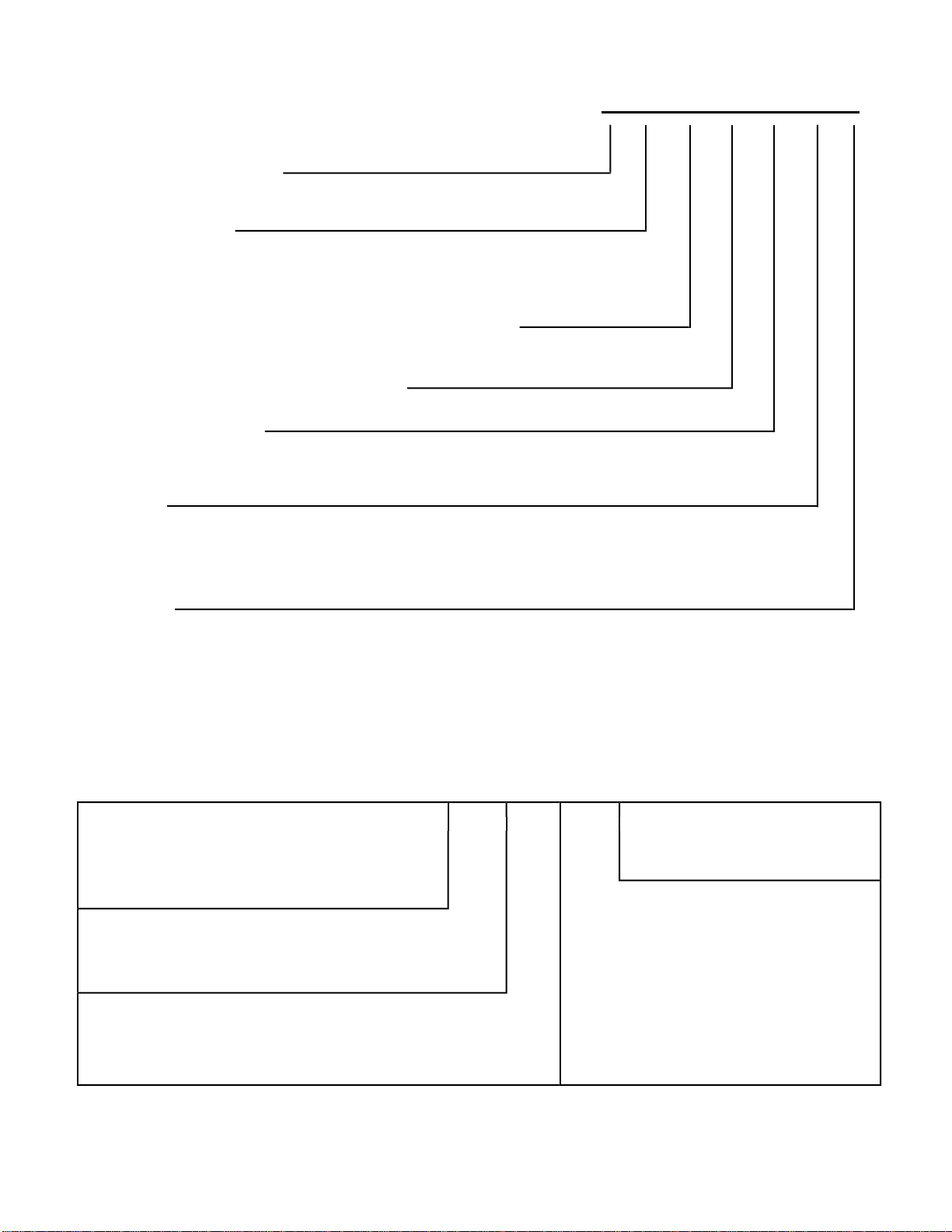
M MODEL NUMBER
1st DIGIT - FUNCTION
W = Thru-The-Wall, WallMaster Series
nd DIGIT - TYP
S = Straight Cool
=
Y = Heat Pump
rd & 4th DIGITS - APPROXIMATE BTU/HR (Coolin
eating BTU/HR capacity listed in Specifi cations/Performance Data Sectio
5th DIGIT - ALPHABETICAL MODIFIER
6th DIGIT - VOLTAGE
1 = 115 Volts
= 230-208 Volt
7th DIGI
= Straight Cool & Heat Pump Models
ELECTRIC HEAT MODEL
3 = 3 KW Heat Strip, Nomina
W S 08 B 1 0 B
th DIGI
ajor Change
RAC SERIAL NUMBER IDENTIFICATION
Serial Numbe
ecade Manufactured
L=0
=1 D=4 G=
B=2 E=5 H=
ear Manufactured
=1 D=4 G=7 K=
B=2 E=5 H=
=3 F=6
Month Manufactured
=Jan D=Apr G=Jul K=Oc
=Feb E=May H=Aug L=Nov
=Mar F=Jun J=Sept M=Dec
F=6
IDE
roduction Run Number
R = RAC
P = PTA
E = EAC
H = Split
uct Line
=
y
PERFORMANCE DATA
r
/
.
a
a
o
o
a
o
G
F
G
F
G
g
p
p
p
t
-
g
SSU
S
C
C
GS
22 REF.
M
g
r
p
.
(
)
(
)
t
e
l
t
ps
g
p
A
8
6
0
5
00
5
A
2
8
8
5
0
0
0
8
0
2
8
2
8
9
2
4
9
3
0
A
5
0
B
8
4
0
3
8
5
4
2
8
0
2
8
3
9
8
7
6
2
A
3
2
9
2
0
4
3
33B
2
3
3
0
5
7
4
8
A
2
8
3
4
0
8
1
2
8
3
2
9
/
4
3
33
2
3
0
/
7
4
0
d
#
g
p
y
/h
g
p
y
/h
t
t
d
g
ps
tts
ps
tts
ff
y
t
o
tu
e
o
l
/
.
d
n
.
—
8
—
5
3
45
—
7
—
5
4
45
0
500
—
0
—
5
3
95
—
8
0
—
60
0
B
—
8
9
—
3
80
09
—
8
5
—
8
90
9
0
0
8
0
0
60
0
3
33B
0
8
9
0
3
80
6
0
8
5
0
8
90
0
A
8
8
5
0
07
3
33A
8
8
2
7
6
/
80
6
d
l
N
b
s
g
k
T
D
F
e
F
)
ll
t
e
S
S
S
5
5A
15P
,
,
A
5A
5P
0,
,
0
A
P
d
l
i
h
h
h
ith
t
i
u
t
i
t
R
i
u
t
i
e
u
th
ll
i
ht
SC
S
"
"
"
"
"
"
"
"
"
–
0 Hertz
Motor
Evap
e in
har
Locked
mps
Amps
ub
uper
s
Am
RPM
F
Z.
Rotor Am
ea
oo
ion Discharg
c
oolin
Hea
1
11
.
.2 2
.1 3
15
15
30
110
9
4
4.
22.
5.
58.0
.
2 297 1
4792939.
4
16
0
0
0
0
74 131
35.0
7.
5.
.5
29
8
1
1 1305
2
5.
5.0
6.
.5
15
30
1
0
07
1200
6
et Weight
m
e Air
Si
35.0
re
7.
15.
15.2 26.0 38.0
va
m
R
Mois
i
.6
.5 5.6
5
300
2
8
1
Energy
icienc
Ra
E
eating
eating
16
16
s
irculatio
Hr
Pints
Wa
Am
3
1
1
1
2
2
2
2
.
.
2.
.
.
.
0.0/10.0
1
2
.
8.9/8.7
11
.2 2
.0/8.
3
1
2
2
.
0.0/10.0
8.9/8.7
16.0/14.7 3550/295
1
23
.2 2
.0/8.
0.0/10.0 2.
.9/4.0 857/821
16.0/14.7 3550/295
11
.2 2
9.0
.0
1182/113
.4/5.
e-wa
r
m
m
n
m
m
n
ept
Sleeve Dimensions
27 1/4
g
e
17 1/4
on
ens
9/16
x
Outsid
on
oom
1/2
ens
o
x
n
3
ron
w
ept
6 3/4
t
g
e
16 3/4
leeve
e
o
W
–
26 1/2
5 3/4
hassis
15
15
115
07
4
30
110
1
92
3
2
.5
7.
5.
38.0
7.
5.
5.0
.6 26.0
89
3
.6 15.
.5
.
89
15
29
2
1
30 7
16
1
1
E
-
AL RATIN
TRI
ELE
RE
RE
OPERATING
2 1
9
Tem
Tem
Tem
. F
DE
out
in
E
F
Dro
i
10
76
51 12
2
5
08B10
10B10
iquid
uction
e
ischar
CONDENSER
.
TEMP. DE
EVAPORATOR
.
emp.
e
TEMP. DE
VAPORATOR AIR
ischar
106 16
179
1179
12
5
2
14B10 A 5
10B30
9
10
54
17
50 12
51 5
9
2
13B30
16B3 0A 5
9
10
10
10
2 9
80
80
80
80
17
26
26
51
5
7
5
E10B33
51
5
51 5
9
9
7
2
5
5
A 5
B
B
Y10B33A 5
Y1
E1
E16B33
Heatin
oolin
Cooling
oolin
acit
Ca
acit
a
Wa
m
e
s Ra
Vol
TU
BTU
el
o
2
.
.
WS08B10A
WS10B10A
1005/996
2.
4.6/5.
30/20
3
0000/10000
WS14B10A
WS10B30A
404/137
756/170
1005/996 16.0/14.7 3550/295
.3/6.7
7.8/8.5
4.6/5.
30/20
30/20
30/20
2500/12000
5800/15000
0000/10000 11000/910
B33A
WS13B30
WS16B30A
WE1
404/137
756/170
.3/6.7
7.8/8.5
30/20
30/20
2500/12000 11000/910
5800/15000 11000/910
B
B33A
WE1
WE1
389/135
1013/976
.4/6.
4.6/4.
30/20
30/20
0100/9800 8100/7800
2500/12100 10400/10000
B33
B
WY1
WY1
n
ti
rm
n Inf
ti
ll
nst
a
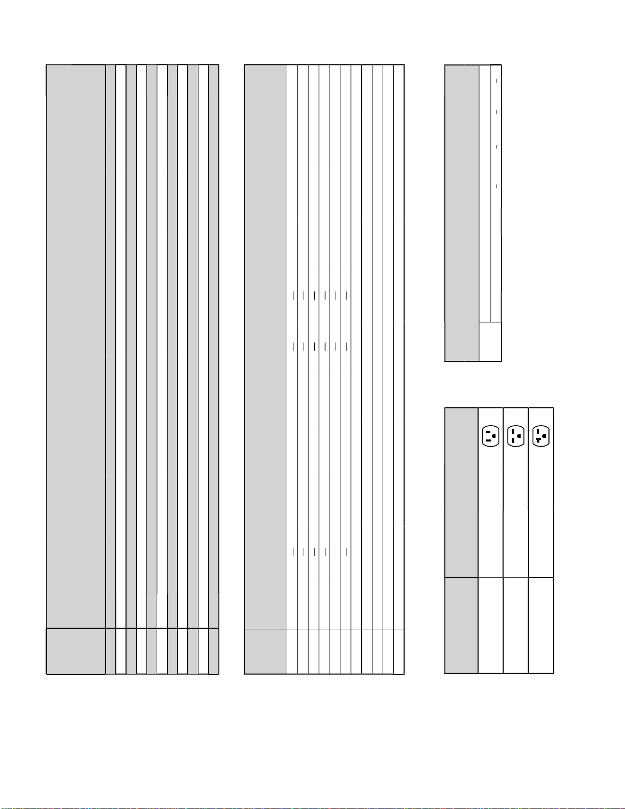
utle
ppearanc
ace
-
- 1
WS13B30A
WS10B30A
V - 1
WS16B30
- 20
50V - 20
WE16
WE13
, WY13
WE1
WY1
ug
NEMA#
us
er
V - 1
-
rea
or
er
um
e
o
12
10B10A,
08B10A, W
14B10 A
W
W
ircuit Ratin
* Rating Conditions: 80 degrees F, room air temp. & 50% relative humidity,with 95 degree F, outside air temp & 40% relative humidit
Calculate the heat loss of the space to be heated. As long as the heat loss does not exceed the resistance heating capacity rating of the unit, the heating performance will be satisfactor y. Change-ove
from heat pump operation to resistance operation on models indicated is automatic at a preset outside ambient temperature of approximately 35°F. If condensate disposal is desired, an optional drain
kit is available. DEFROST CONTROL: Initiated at 20°F (outdoor coil temperature) and terminated at 43°F (outdoor coil temperature). During defrost, the compressor stops and the electric heat starts,
then operates with the fan to maintain indoor comfor t. Below 43°F, the unit remains in electric heat mode. During electric heat mode, the unit will achieve the following ratings: 11000
6.0/14.7 amps, and 3550/2950 watts. DEFROST DRAIN: Drain automatically opens at approximately 50°F in outdoor base pan for defrost condensate disposal
9100 BTU/h,
.
g
d.
each of se
ce
use an extension cord
o
.
.
A
.
.
.
ELECTRICAL DATA
Wire Size Use ONLY wiring size recommended for
single outlet branch circuit
Fuse/Circuit Use ONLY type and size fuse or HACR
Breaker circuit breaker indicated on unit’s ratin
plate. Proper current protection to the unit
is the responsibility of the owner.
Grounding Unit MUST be grounded from branch
ircuit through service cord to unit, or
through separate ground wire provided on
permanently connec ted units. Be sure that
branch circuit or general purpose outlet is
rounde
eceptacle The fi eld supplied outlet must match plug on
rvice cord and be within r
ord. Do NOT alter the service cord or plug.
NOT
the table above for proper receptacle and
use type.
rvi
. Refer t
LECTRIC SHOCK HAZARD
Turn off electric power before service or installation
ll electrical connections and wiring MUST be
installed by a qualifi ed electrician and conform to the
ational Elect rical Code and all local codes whic h
ave jurisdiction
Failure to do so can result in property damage,
ersonal injury and/or death
The consumer - through the AHAM Room Air Conditioner Certifi cation Program - can be certain
that the AHAM Certifi cation Seal accurately states the unit’s cooling and heating capacity rating,
the amperes and the energy effi ciency ratio

FUNCTIONAL
CO
S
e
°F.
y
ffuse
used to direc
.
heel
.
g
.
s
at
l
y
.
p
y
®
switch
.
d
g
p
®
models.
p
p
g
e
.
py
)
MPONENT
A. Mechanical components
Bellows condensate valv
Temperature-sensitive valve that opens up to drain off condensate water when the outside temperature falls below 40°F
and closes when the outside temperature reaches 58
i
r with directional louvers
wer w
Attaches to the indoor side of the fan motor shaft and is used for distributing unconditioned, room side air though the heat
xchanger and delivering conditioned air into the room
Attaches to the outdoor side of the fan motor shaft and is used to move outside air through the condenser coil, while
slinging condensate water out of the base pan and onto the condenser coil, thus lowering the temperature and pressures
within the coil
t the conditioned airfl ow
. Electrical component
Thermost
sed to maintain the specifi ed room side comfort leve
sed to regulate the operation of the fan motor, the compressor or to turn the unit off. For troubleshooting, refer to the
wiring diagrams and schematics in the back of this service manual
educes line current and steadies the voltage supply, while greatly improving the torque characteristics of the fan motor
and compressor motor .
When engaged, it sends the power supply to the fan motor through the thermostat, which allows for a cycle-fan operation
n Motor
ual-shafted fan motor operates the indoor blower wheel and the condenser fan blade simultaneously.
lenoi
sed to energize the reversing valve on all heat pump units.
lectric resistance heater, available in 3.3, 4.0 or 5.2 kW on select TwinTem
sed to provide better thermostat and room air temperature control.
C. Hermetic components
otorized device used to compress refrigerant through the sealed system.
A four-way switching device used on all heat pump models to change the fl ow of refrigerant to permit heating or cooling.
heck valv
A pressure-operated device used to direct the fl ow of refrigerant to the proper capillary tube, during either the heating or
ooling cycle
A cylindrical meter device used to evenly distribute the fl ow of refrigerant to the heat exchangers (coils.
YSTEM CONTROL PANEL
)
E
”
Acti
”
WS
ode is ac
e.
gging
onfunctiona
y
y
.
l
)
e
”
button o
WS models
T
/
g
.
S
d
)
g
Code Mode
.
y
.
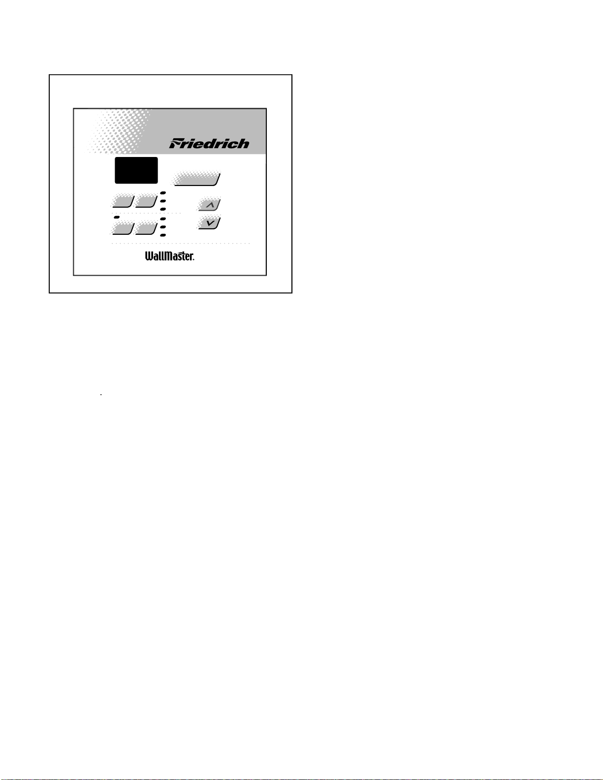
“WS” Models
Figure 6: System Control Pane
PM
Speed
Timer
On/Off
72
Fan
Mode
Hour
Set
Cool
Money Saver
Fan Only
Clock
Start Time
Stop Time
Power
®
Tem p/ Hou r
ESTING THE ELECTRONIC CONTROL
CHECKING ROOM TEMPERATUR
1. Check the room temperature at the electronic c ontrol
pad by pressing at the same time the
utton and the temperature
UP” button on XQ
odels
2. The indoor temperature will display for 10 seconds.
Indoor temperature can be viewed in all modes,
including the TEST mode. The display can be changed
back to SET temperature by pressing any key, except
the ON/OFF button, or after 10seconds has elapsed.
ACTIVATING TEST MODE
vate test mode by pressing at the same time the
utton and the temperature
DOWN” button on XQ
odels. LEDs for Hour , Start, and Stop will blink 1bps while
Test M
tiv
Test Mode has duration of 90 minutes. Test Mode
an be activated under any conditions, including Off.
Test Mode is cancelled by pressing the On/Off button,
unplu
the unit, or when the 90 minutes is timed
ut. All settings revert to the factory default settings of
ool, 75 degrees F, Timer and Set Hour features are
n
l.
FAN SPEED
WS
MODE
Activating Error Code Mode
ubmode of Test Mode
nit must be in T est Mode to enter Error Code Mod
1. Activate Error Code Mode by pressing the
ON/OFF
n XQ
LED for the
TIMER ON/OFF” will fl ash 1bps while Error Code
ode is active. Pressing the
TEMP/HR+ ” button will
display 00. Consecutive presses will scroll t hrough all
rror codes logged. Press the
TEMP/HR
tton
to see the reverse order of all error codes logged.
When the end of logged error codes is reached the
temperature set point will appear.
MPORTAN
rror Codes are cleared from the log by exiti ng from Error
ode Mode. To e xit on XQ & WS models, press Timer On
button. Or unplug unit to exit Error Code Mode. Plu
unit in after 5 seconds to resume normal operation of unit
RROR CODE LIS TING
1 SHORT CYCLE SITUATION: Defi ned as
ompressor powered on before the three minute
time delay ten times in one hour. Investigate an
orrect short cycling problem.
2 KEYBOARD STUCK ER ROR: If key button(s
are pressed continuously for twenty seconds or
more. If
ODEkey is stuck, unit will default to
ool. Exit Error Code Mode to see if error “E2”
is no longer displayed and unit is functioning.
eplace board if “E2” still displays after exitin
rror
.
3 FROST PROBE OPEN: Normal operation is
allowed. Ohm frost probe. Replace probe if ohm
value not read. If ohm value present replace
rd.
4 FROST PROBE SHORT: Normal operation
allowed. Replace probe.
5 INDOOR PROBE OPEN: Control assumes
indoor ambient temperature is 90 degree F and
unit will operate. Ohm indoor probe. Replace
robe if ohm value not read.
6 INDOOR PROBE SHORT: Control assumes
ambient temperature is 90 degree F and unit will
perate. Replace probe
T est Mode overrides the three-minute lockout, all dela
or compressor and fan motor start / speed change, and
no dela
when switching modes
Test M ode default settings are ON, Money Saver, 60
degrees F, and High fan speed.
s
NOTE: All Error Code displays for Frost & Indoor Probe
will allow unit to operate. Unit may or will ice up if fault
omponents not replaced
 Loading...