

Friedrich Metal Products US08B10A-A Service Manual
Unifit. Cool (04/06)
Thru-the-Wall Series
Thru-the-Wall Series
Service and Parts
Manual
115 Volts US08B US10B US12B
230 Volts US10B US12B

—2—
1. PREFACE
1.1 SAFETY PRECAUTIONS ...............................2
1.2 INSULATION RESISTANCE TEST.................2
1.3 SPECIFICATIONS ..........................................3
1.4 FEATURES.....................................................5
1.5 CONTROL LOCATIONS.................................5
2.
DISASSEMBLY INSTRUCTIONS
2.1 MECHANICAL PARTS....................................6
2.1.1 FRONT GRILLE.....................................6
2.1.2 CABINET................................................6
2.1.3 CONTROL BOX.....................................6
2.2 AIR HANDLING PARTS..................................7
2.2.1
ORIFICE, HEATER ASSY AND TURBO FAN
.........7
2.2.2 FAN........................................................7
2.2.3 SHROUD................................................8
2.3 ELECTRICAL PARTS.....................................8
2.3.1 MOTOR..................................................8
2.3.2 COMPRESSOR.....................................8
2.3.3 CAPACITOR..........................................8
2.3.4 POWER CORD......................................9
2.3.5 THERMISTOR .......................................9
2.4 REFRIGERATION CYCLE.................................10
2.4.1 CONDENSER......................................10
2.4.2 EVAPORATOR....................................10
2.4.3 CAPILLARY TUBE...............................10
3.
TROUBLESHOOTING GUIDE
3.1 OUTSIDE DIMENSIONS...............................13
3.2 PIPING SYSTEM ..........................................13
3.3 TROUBLESHOOTING GUIDE......................14
4. SCHEMATIC DIAGRAM
4.1 CIRCUIT DIAGRAM......................................19
5. EXPLODED VIEW..................................20
6. REPLACEMENT PARTS LIST.......21
1. PREFACE
This SERVICE MANUAL provides various service information, including the mechanical and electrical
parts etc. This room air conditioner was manufactured and assembled under a strict quality control system.
The refrigerant is charged at the factory. Be sure to read the safety precautions prior to servicing the unit.
1.1 SAFETY PRECAUTIONS
1. When servicing the unit, turn off the air conditioner
and unplug the power cord.
2. Observe the original lead dress.
If a short circuit is found, replace all parts which
have been overheated or damaged by the short
circuit.
3. After servicing the unit, make an insulation
resistance test to protect the customer from being
exposed to shock hazards.
1.2
INSULATION RESISTANCE TEST
1. Unplug the power cord and connect a jumper
between 2 pins (black and white).
2. The grounding conductor (green or green & yellow)
is to be open.
3. Measure the resistance value with an ohm meter
between the jumpered lead and each exposed
metallic part on the equipment.
4. The value should be over 1MΩ.
CONTENTS
US08B10A-A US10B10A-A US12B10A-A
—3—
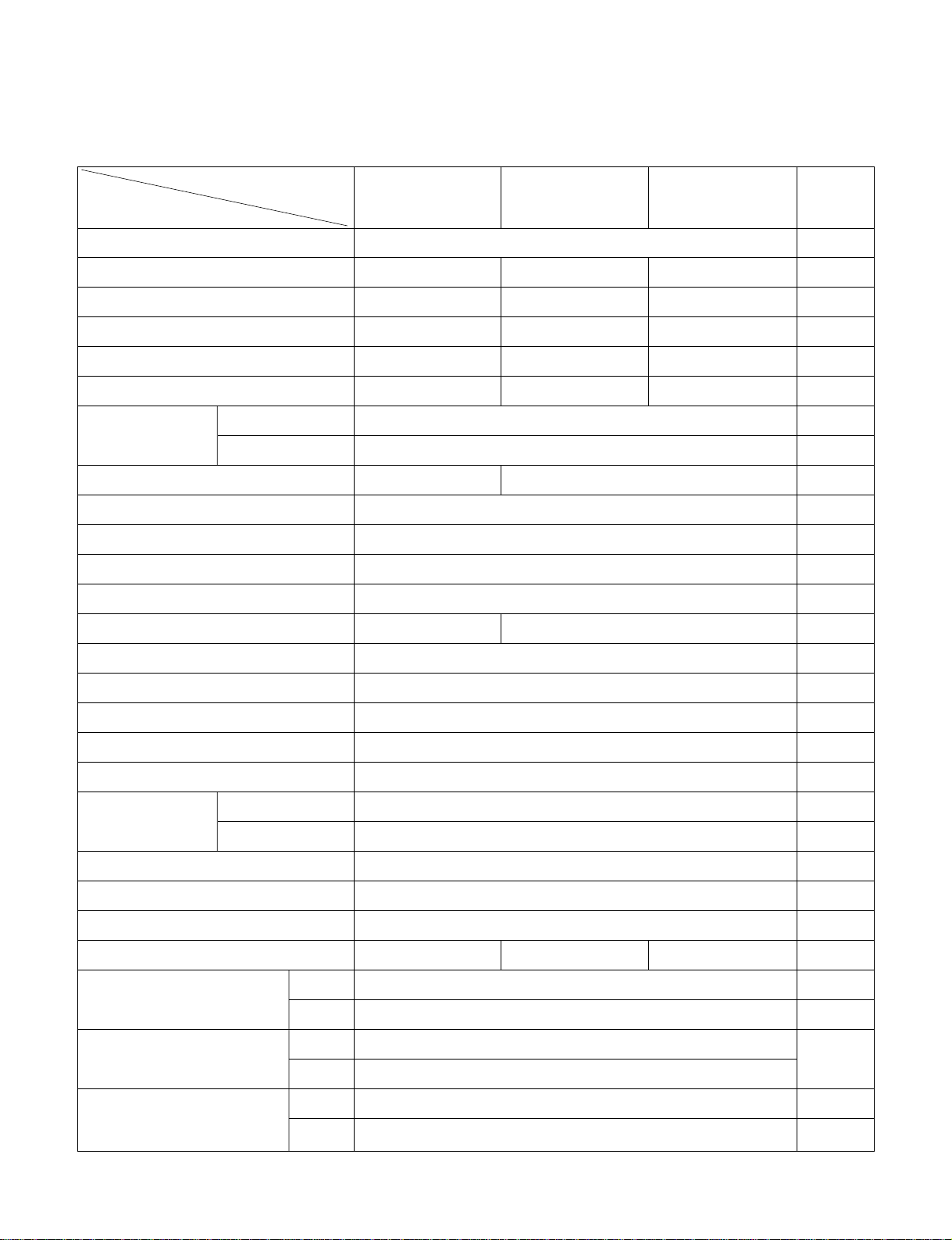
1.3 SPECIFICATIONS
1.3.1 FOR US08B10A-A/US10B10A-A/US12B10A-A
POWER SUPPLY
COOLING CAPACITY (Btu/h)
INPUT (W)
RUNNING CURRENT (A)
E.E.R (Btu/w.h)
REFRIGERANT (R-22) CHARGE(g)
OPERATING
INDOOR (°C)
TEMPERATURE
OUTDOOR (°C)
EVAPORATOR
CONDENSER
FAN, INDOOR
FAN, OUTDOOR
FAN SPEEDS, FAN/COOLING
FAN MOTOR
OPERATION CONTROL
ROOM TEMP. CONTROL
AIR DIRECTION CONTROL
CONSTRUCTION
PROTECTOR COMPRESSOR
FAN MOTOR
POWER CORD
DRAIN SYSTEM
NET WEIGHT (lbs/kg)
DIMENSION (inch)
(W x H x D) (mm)
SLEEVE DIMESION (inch)
(W x H x D) (mm)
SLEEVE DEPTH (inch)
WITH FRONT GRILLE (mm)
1Ø, 115V, 60Hz
8,000 9,800 11,500
830 1,110 1,310
7.5 10.2 12.0
9.6 8.8 9.4
540g(19.1OZ) 475g(16.8OZ) 485g(17.1OZ)
26.7(DB) 19.4(WB)
35(DB) 23.9(WB)
2 ROW 12STACKS 3 ROW 12STACKS
2ROW 17STACKS, L-BENDING TYPE
LOUVERED-FIN TYPE
TURBO FAN
PROPELLER TYPE FAN WITH SLINGER-RING
3/3
6 POLES 4POLES
ELECTRIC
THERMISTOR
VERTICAL LOUVER(RIGHT & LEFT)
HORIZONTAL LOUVER(UP & DOWN)
TOP-DOWN
EXTERNAL OVERLOAD PROTECTOR
INTERNAL THERMAL PROTECTOR
2.3m (3WIRES WITH GROUNDING)
ATTACHMENT PLUG(CORD-CONNECTED TYPE, LCDI)
SPLASHED BY FAN SLINGER
73/33 78/35 80/36
24 x 1413/32 x 20 3/32
610 x 366 x 499
25 7/
8 x 15
17
/
32 x 16
23
/
32
656 x 394 x 425
20 1/
2
521
MODELS
REMARK
ITEMS
OPTIONAL
PART
—4—
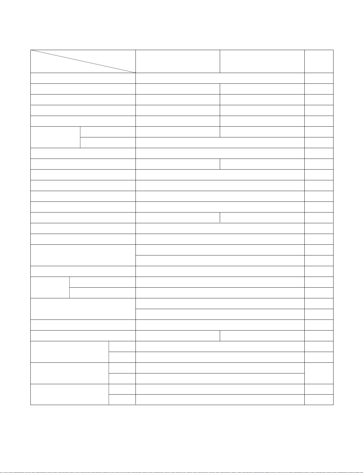
1.3.2 FOR US10B30A-A/US12B30A-A
REMARK
POWER SUPPLY
COOLING CAPACITY (Btu/h)
INPUT (W)
RUNNING CURRENT
(A)
E.E.R. (Btu/W.h)
INDOOR (°C)
OUTDOOR (°C)
REFRIGERANT (R-22) CHARGE(g)
EVAPORATOR
CONDENSER
FAN, INDOOR
FAN, OUTDOOR
FAN SPEEDS (FAN/COOLING/HEATING)
FAN MOTOR
OPERATION CONTROL
ROOM TEMP. CONTROL
CONSTRUCTION
COMPRESSOR
FAN MOTOR
DRAIN SYSTEM
NET WEIGHT (lbs/kg)
DIMENSION (inch)
(W x H x D) (mm)
SLEEVE DIMESION (inch)
(W x H x D) (mm)
SLEEVE DEPTH (inch)
WITH FRONT GRILLE (mm)
1Ø, 230/208V, 60Hz
10,000/9,800 11,700/11,400
1,060/1,040 1,250/1,210
4.7/5.2 5.8/6.2
9.4/9.4 9.4/9.4
490g(17.3OZ) 475g(16.8OZ)
26.7(DB) 19.4(WB)
35(DB) 23.9(WB)
2 ROW 12STACKS 3 ROW 12STACKS
2ROW 17STACKS, L-BENDING TYPE
TURBO FAN
PROPELLER TYPE FAN WITH SLINGER-RING
3/3
6 POLES 4POLES
ELECTRIC
THERMISTOR
VERTICAL LOUVER(RIGHT & LEFT)
HORIZONTAL LOUVER(UP & DOWN)
TOP-DOWN
EXTERNAL OVERLOAD PROTECTOR
INTERNAL THERMAL PROTECTOR
1.4m (3WIRES WITH GROUNDING)
ATTACHMENT PLUG(CORD-CONNECTED TYPE, LCDI)
SPLASHED BY FAN SLINGER
78/35 80/36
24 x 14
13
/
32 x 20
3
/
32
610 x 366 x 499
25 7/
8
x 15
17
/
32
x 16
23
/
32
656 x 394 x 425
20 1/
2
521
MODELS
ITEMS
OPERATING
TEMPERA-TURE
AIR DIRECTION CONTROL
POWER CORD
PROTECTOR
LOUVERED-FIN TYPE
US10B30A-A US12B30A-A
OPTIONAL
PART
1.4 FEATURES
• Designed for cooling only.
• Powerful and quiet.
• Slide out chassis for the simple installation and service.
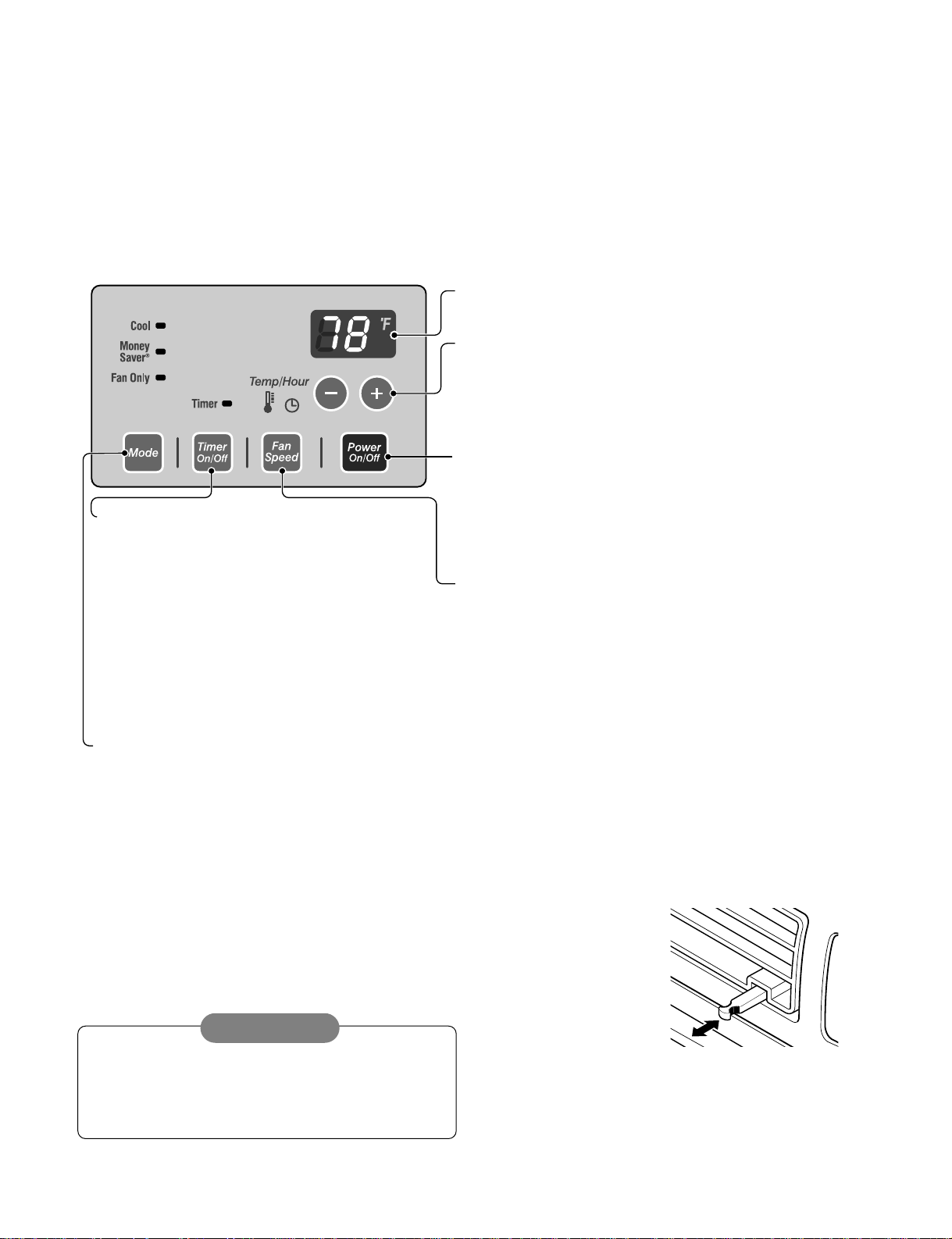
1.5 CONTROL LOCATIONS
1.5.1 COOLING ONLY MODEL
• OPERATION
• Built in adjustable THERMOSTAT.
• Washable one-touch filter.
• Compact size.
• VENTILATION
Push the lever to the "CLOSE" position to cool, heat or recirculate room air only.
Pull the lever to the "OPEN" position to exhaust smoke or stale air from the room.
This feature is best used in conjunction with the FAN ONLY position.
—5—
PULL OPEN / PUSH CLOSE
REMOTE CONTROL SIGNAL RECEIVER
POWER
MODE
-
Push this button to shift mode of operation from COOL
→ MONEY SAVER → FAN.
- COOL :
• Fan runs continuously for normal cooling operation.
- MONEY SAVER:
• The fan stops when the compressor stops cooling. Approximately every 3 minutes the fan will turn on and the unit will check
the room air to determine if cooling is needed.
- FAN :
• Fan-only operation.
TIMER
- SHUT-OFF TIME
• You will usually use shut-off time while you sleep.
• If unit is running, use Timer to set number of
hours until shut-off.
• For your sleeping comfort, once Timer is set, the
Temperature setting will raise 2°F after 30 min.,
and once again after another 30 min.
• Push Timer button to advance setting from 1 Hour
→
2 Hours
→
....
→
12 Hours maximum.
- START TIME
• If unit is off, use Timer to set number of hours before unit starts.
• Push Timer button to advance setting from 1 Hour
→
2 Hours
→
.....
→
12 Hours maximum.
TEMPERATURE SETTING
• Use this button to automatically control the temperature of the room.
The temperature can be set within a range of 60°F to 86°F by
increments of 1°F.
• The setting appears in the display.
• To turn the air conditioner ON, push this button.
To turn the air conditioner OFF, push the button again.
• This button takes priority over any other button.
• When you first turn it on, the unit is in cool mode, at High fan
speed, and set at a temperature setting of 72°F.
FAN SPEED
• Every time you push this button, it advances the setting as follows:
{High → Low → Med → High}
When the air conditioner has been operating in the
cooling and is turned off or set to the fan only position,
wait at least 3 minutes before resetting to the cooling
operation again.
CAUTION
—6—
2.1 MECHANICAL PARTS
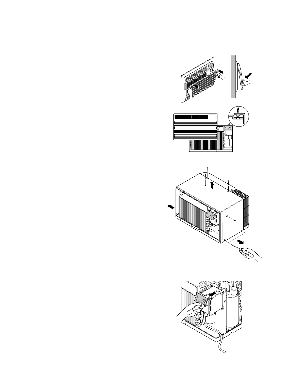
2.1.1 FRONT GRILLE
1. Open the inlet grille downward.
2. Remove the screw which fastens the front grille.
3. Pull the front grille from the right side.
4. Remove the front grille. (See Fig. 1)
5. Re-install the component by referring to the
removal procedure.
2.1.2 CABINET
1. After disassembling the FRONT GRILLE, remove
the 6 screws which fasten the cabinet at the both
sides and the top. (See Fig. 2)
Keep these for later use.
2.1.3 CONTROL BOX
1. Remove the front grille. (Refer to section 2.1.1)
2. Remove the screw which fasten the control
box. (See Fig. 3)
3. Pull the control box from the barrier.(See Fig.3)
4. Discharge the capacitor by placing a 20,000 ohm
resistor across the capacitor terminals.
5. Disconnect two wire housings in the control box.
6. Pull the control box forward completely.
7. Re-install the components by referring to the
removal procedure. (See Fig. 3)
(Refer to the circuit diagram found on page 19 in
this manual and on the control box.)
2. DISASSEMBLY INSTRUCTIONS
— Prior to disassembling the unit, make sure that the POWER is off and the power cord is unplugged from the
wall receptacle.
Figure 1
Figure 2
Figure 3
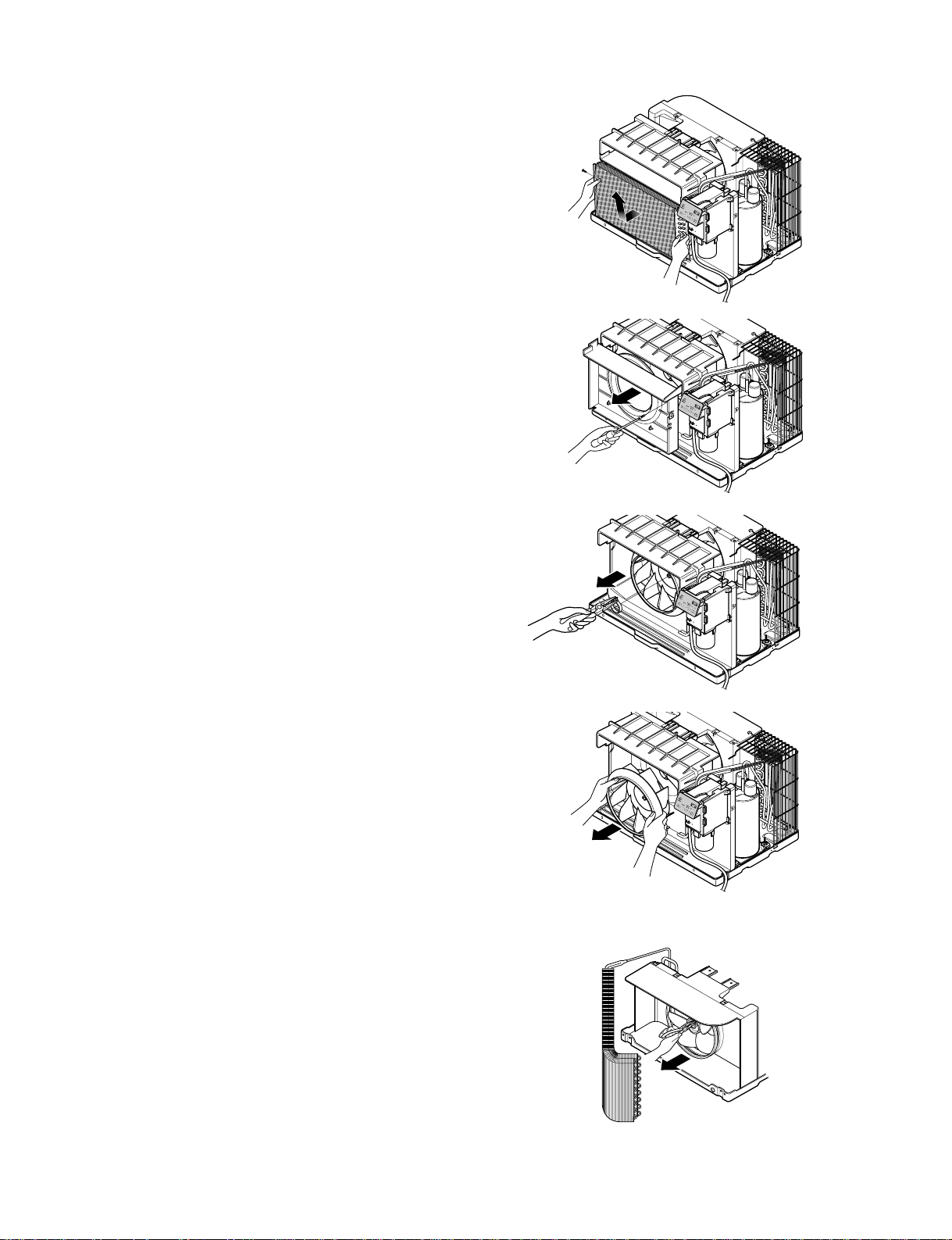
Figure 7
—7—
2.2 AIR HANDLING PARTS
2.2.1 ORIFICE, AND TURBO FAN
1. Remove the front grille. (Refer to section 2.1.1)
2. Remove the cabinet. (Refer to section 2.1.2)
3. Remove the 2 screws which fasten the
evaporator at the left side and the right side.
(See Fig. 4)
4. Move the evaporator to the side carefully.
5. Remove the orifice. (See Fig. 5)
8. Using handheld pliers, remove the clamp which
secures the turbo fan. (See Fig. 6)
9. Remove the turbo fan with pliers or your hand,
without touching blades. (See Fig. 7)
10. Re-install the components by referring to the
removal procedures, above.
2.2.2 FAN
1. Remove the cabinet. (Refer to section 2.1.2)
2. Remove the brace.
(Refer to section 2.2.1)
3. Remove the 7 screws which fasten the condenser.
4. Move the condenser to the side carefully.
5. Using handheld pliers, remove the clamp which
secures the fan.
6. Remove the fan. (See Fig. 8)
7. Re-install the components by referring to the
removal procedures, above.
Figure 4
Figure 5
Figure 6
Figure 8
—8—
2.2.3 SHROUD
1. Remove the fan. (Refer to section 2.2.2)
2. Remove the shroud. (See Fig. 9)
3. Re-install the components by referring to the
removal procedures, above.
2.3 ELECTRICAL PARTS
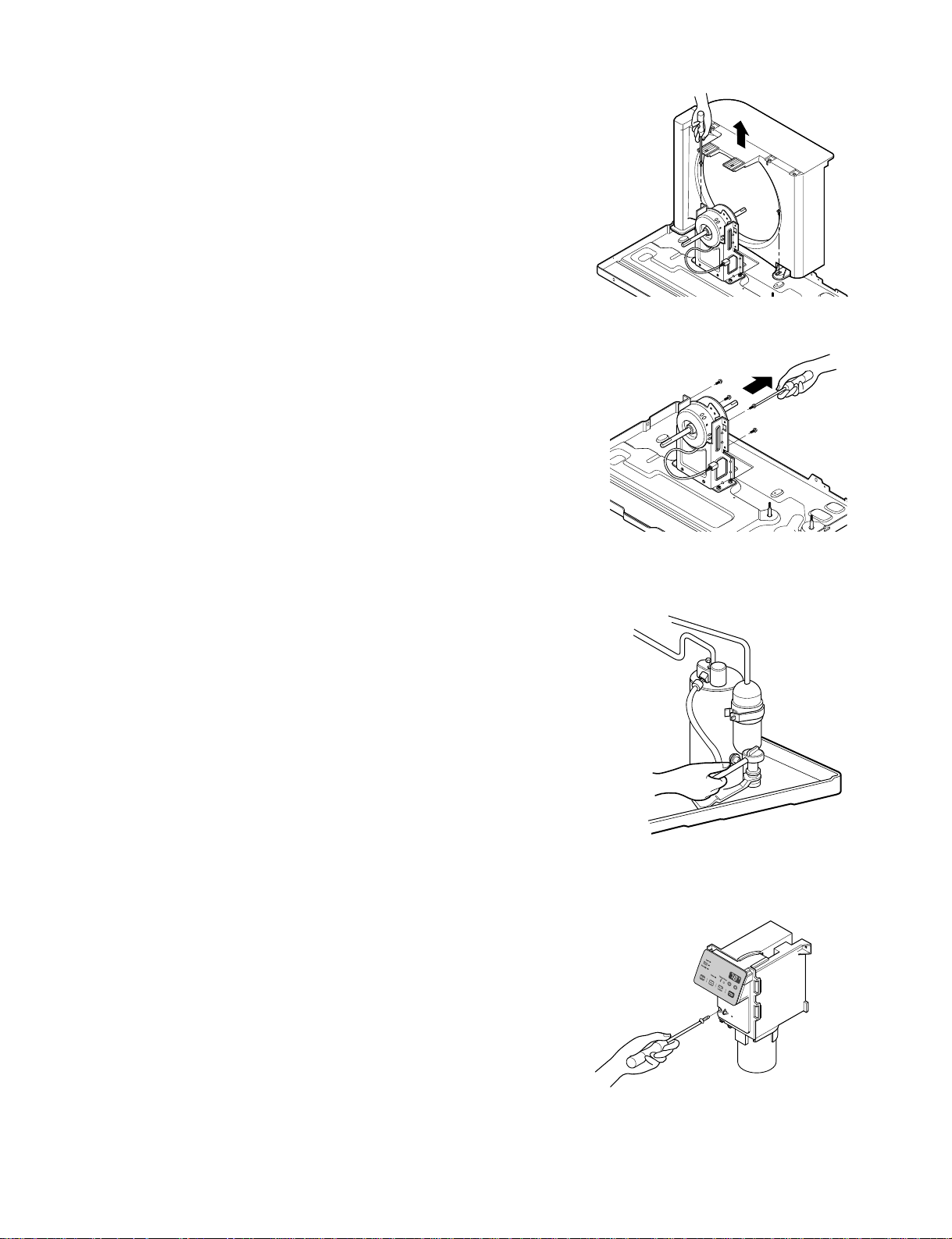
2.3.1 MOTOR
1. Remove the cabinet. (Refer to section 2.1.2)
2. Remove the clamp cord and disconnect the wire
housing in control box. (Refer to section 2.1.3)
3. Remove the turbo fan. (Refer to section 2.2.2)
4. Remove the fan. (Refer to section 2.2.2)
5. Remove the 4 or 2 screws which fasten the motor.
(See Fig. 10)
6. Remove the motor.
7. Re-install the components by referring to the
removal procedures, above.
2.3.2 COMPRESSOR
1. Remove the cabinet. (Refer to section 2.1.2)
2. Discharge the refrigerant system using a Freon
TM
Recovery System.
Install a valve for recovery before venting the
Freon. Remove the valve when finished.
3. Disconnect the 3 leads from the compressor.
4. After purging the unit completely, unbraze the
suction and discharge tubes at the compressor
connections.
5. Remove the 3 nuts and the 3 washers which
fasten the compressor. (See Fig. 11)
6. Remove the compressor.
7. Re-install the components by referring to the
removal procedures, above.
2.3.3 CAPACITOR
1. Remove the control box. (Refer to section 2.1.3)
2. Remove the 1 screw
3. Open the control box
4. Disconnect all the leads on the capacitor terminals.
5. Re-install the components by referring to the
removal procedures, above.
Figure 9
Figure 10
Figure 11
Figure 12
 Loading...