

Friedrich Metal Products PDXDL Installation Manual
Model PDXDL
Installation Instructions
CONTROL DOOR LOCK KIT
For Use With Packaged Terminal Units
Please read these instructions completely before attempting installation.
NOTE: These instructions apply to the Control Door Lock Kit ONLY..
WARNING
Electrical shock hazard. Disconnect all power at unit
and main disconnect box. Failure to do so can result
in personal injury, property damage and/or death.
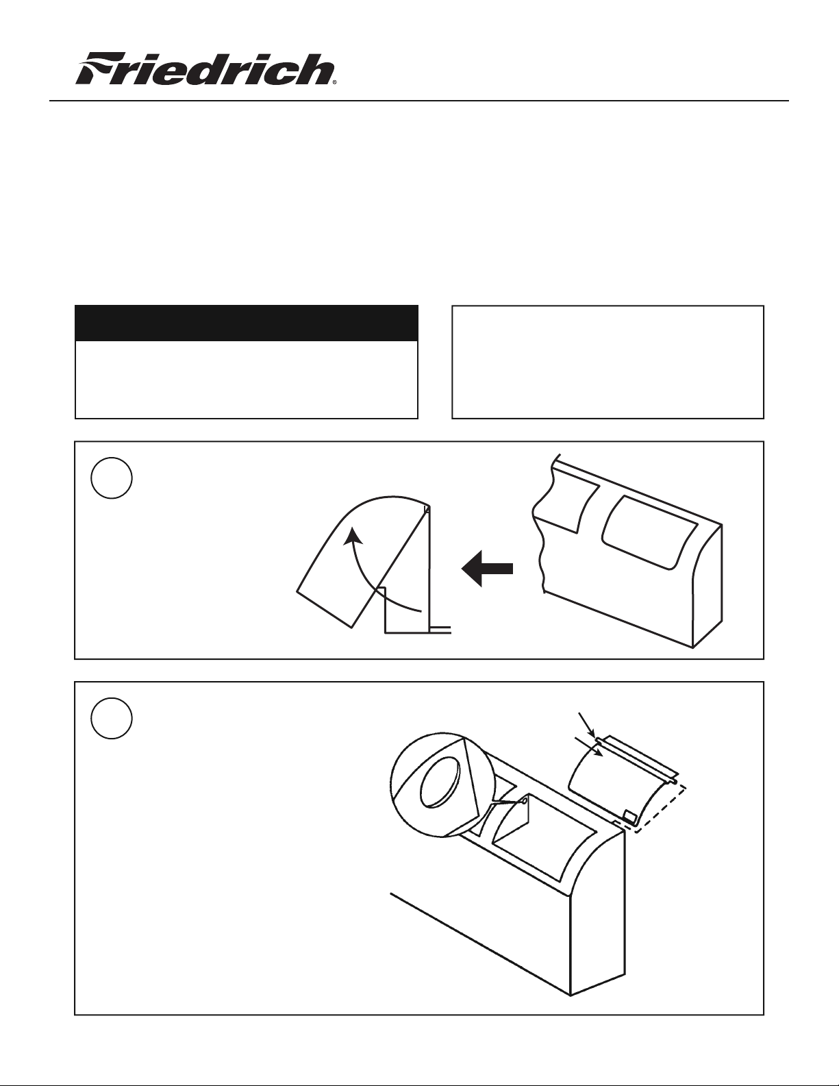
Rotate and lift front panel up
1
2
and remove from chassis.
Press firmly on the upper left
corner of the control door until
pin snaps out of position. Remove
door from front panel.
NOTE: Pin must snap free before
door can be removed.
Ensure that all of the following parts are included
with this kit before attempting installation:
Lock cylinder (1)
Keys (2)
Lock Cam (1)
0USHDOWNHERE
Spur Washer (1)
Cylinder Nut (2)
Cam Nut (1)
0IN
Spacer (1)
920-160-30 Rev.01 (6-05)
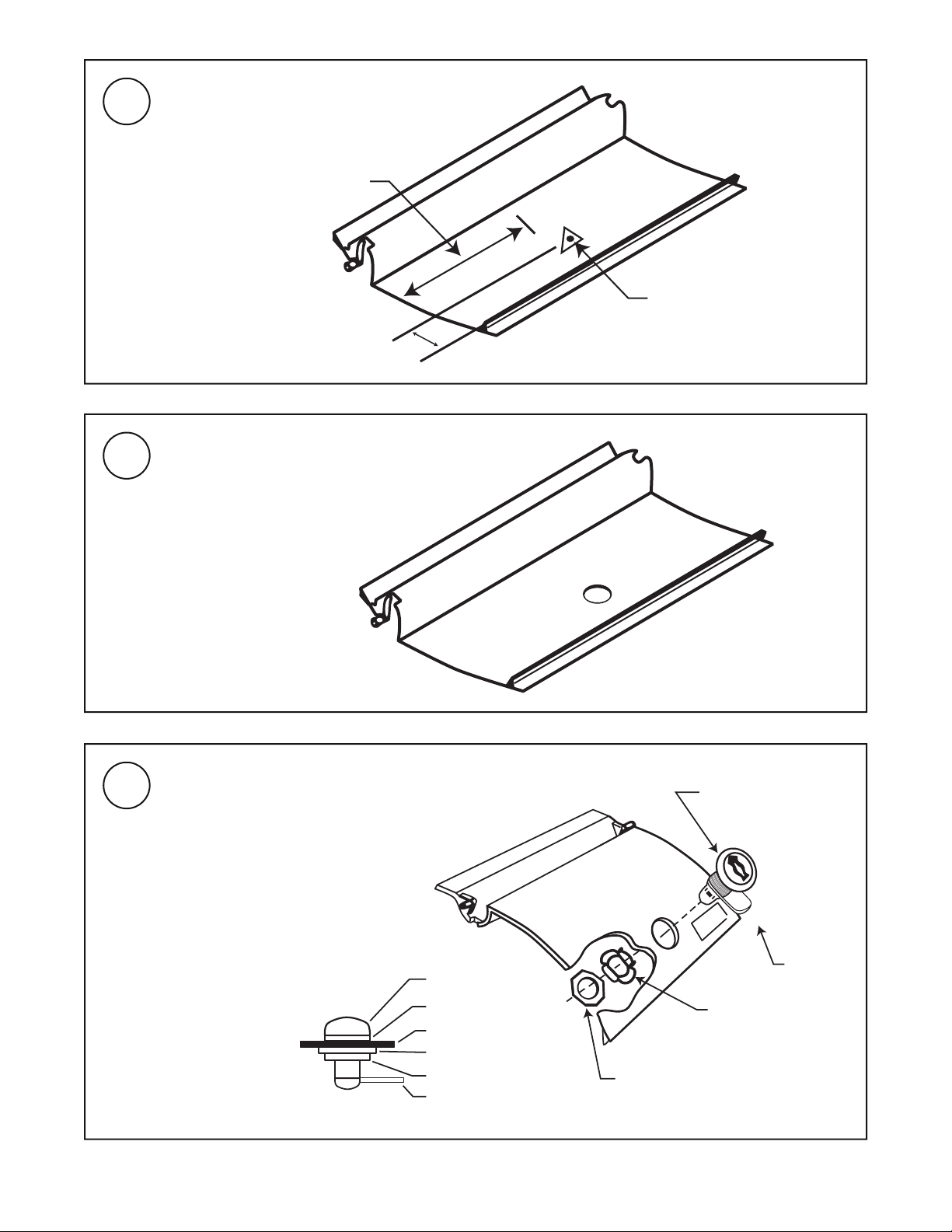
3
Mark pilot hole in back of control
door as shown.
5
/8
4
Pilot hole with triangle outside
4
5
1 1/8"
Place door on a clean surface and
secure in place. Drill a 3/4" hole in door,
using pilot hole to center drill bit. Clean
any rough edges from around hole.
Install lock cylinder in hole as shown.
Install spur washer with spurs toward
door. Complete assembly with cylinder
nut, lock cam and cam nut.
NOTE: Spur washer is intended to
keep lock cylinder from turning in hole.
When cylinder is in place and oriented
as shown, tighten all nuts securely.
NOTE:
Lock Cylinder
(Note orientation
of key slot)
Lock
Spacer
Door
Spur Washer
Lock Nut
Lock Cam
Lock Cam
Spur Washer
(Note position
of flat sides)
Cylinder Nut
920-160-30 Rev.01 (6-05)
 Loading...