


Friedrich Metal Products CP10F10 Service Manual
Room Air Conditioner
Service and Parts
Manual
CP10 - CP12 Svc Parts 2010 (05/10)
Timer
0
F
Mode
ff
0n/
0
Fan Only
Cool
hr
®
Dry
Money Saver
Auto
Fan
Speed
Power
Swing
Temp
115Volts
CP10F10 CP12F10

2 Room Air Conditioner
Air Conditioner Service Manual
TABLE OF CONTENTS
Safety Precautions ..........................................................................................................................................3
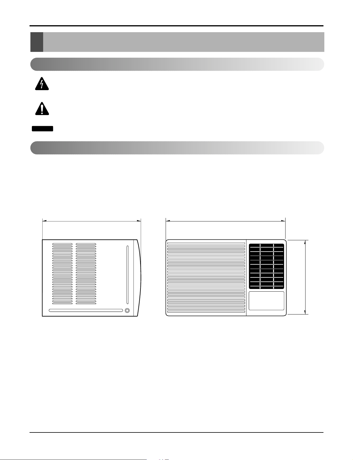
Dimensions .....................................................................................................................................................6
Outside Dimensions ...................................................................................................................................6
Product Specifications ..................................................................................................................................7
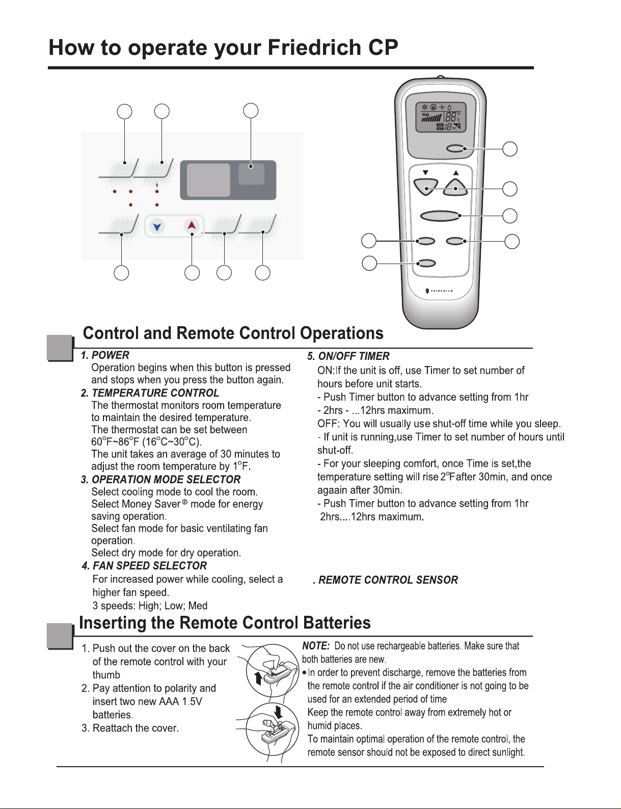
How to operate your Friedrich CP
.......................................................
Controls and Remote Control Operations .................................................................................................8
Disassem bly .................................................................................................................................
....................9
Mechanical Parts.................................................................................................................
.......................9
Air Handling Parts ...................................................................................................................................10
Electrical Parts .........................................................................................................................................11
Refrigerating Cycle...................................................................................................................................12
Schematic Diagram .......................................................................................................................................15
Wiring Diagram.........................................................................................................................................15
Electronic Control Device.........................................................................................................................16
Trou bleshooting Guide .................................................................................................................................17
Piping System ........................................................................................................................................17
Troubleshooting Guide .............................................................................................................................18
Exploded View ..............................................................................................................................................26
Replacement Parts List ................................................................................................................................27
.......................
........................8
.......................
Safety Precautions
CAUTION
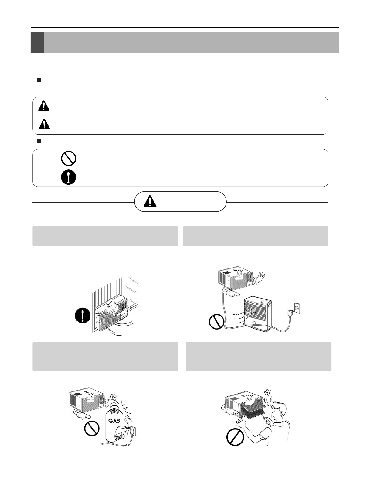
Safety Precautions
To prevent injury to the user or other people and property damage, the following instructions
must be followed.
Incorrect operation due to ignoring instructions will cause harm or damage. The seriousness
is classified by the following indications.
WARNING
Meanings of symbols used in this manual are as shown below.
This symbol indicates the possibility of death or serious injury.
This symbol indicates the possibility of injury or damage to property only.
Be sure not to do.
Be sure to follow the instruction.
WARNING
Always install the expansion panel(s).
• Improper assembly or installation may cause
incorrect operation, including injury, fire, and
electric shock hazards.
Do not place the power cord near a heater.
• It may cause fire and electric shock.
Do not use the power cord near flammable
gas or combustibles such as gasoline,
benzene, thinner, etc.
• It may cause explosion or fire.
Do not disassemble or modify products.
• It may cause failure and electric shock.
Service Manual 3
Safety Precautions
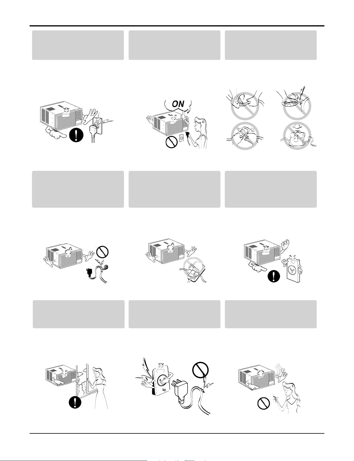
Plug in the power plug
properly.
• Otherwise, it will cause
electric shock or fire.
Do not modify power corDo not modify poDo not modify po dwer cor
Do not modify po
length.
Do not operate or stop the
unit by inserting or pulling
out the power plug.
• It will cause electric shock or
fire.
Use the air conditioner on a
single outlet circuit.(see page 7.)
Do not share the outlet with
other appliances.
Do not damage or use an
unspecified power cord.
• It will cause electric shock or
fire.
Always plug into a
grounded outlet.
• •• It will cause electr ic shoc• k or
fire.
Ventilate before operating air
conditionerwhen gas goes
out.
It may cause explosion, fire,
and burn.
•
It will cause electric shock or
fire.
Do not use the socket if it is
loose or damaged.
•• It may cause fire and electric
shock.
• No •• grounding • may cause
electric shock.
Do not operate with wet
hands or in damp
environment.
• It will cause electric shock.
4 Room Air Conditioner
Service Manual 5
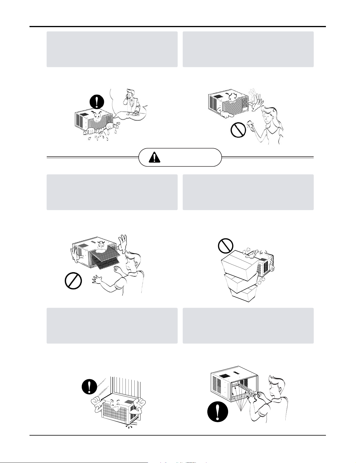
Safety Precautions
If water enters the product, turn off the the
power switch of the main body of appliance.
Contact service center after taking the powerplug out from the socket.
• It will cause electric shock or failure of
machine.
CAUTION
Never touch the metal parts of the unit
when removing the filter.
Do not clean the air conditioner with water.
• Water may enter the unit and degrade the
insulation. It may cause an electric shock.
Do not block the inlet or outlet.
They are sharp and may cause injury.
••
Ensure that the outer caseis not damaged
by age orwear.
Leaving it damaged couldresult in the air
conditioner falling out of the window, creating
a safety hazard.
It may cause failure of appliance or
•
performance deteriorate.
Be cautious not to touch the sharp edges
•
when installing.
It may cause injury.
•
Sharp
edges
6 Room Air Conditioner
Dimensions
Dimensions
Outside Dimensions
This symbol alerts you to the risk of electric shock.
This symbol alerts you to hazards that could cause harm to the
air conditioner.
This symbol indicates special notes.
NOTICE
Symbols Used in this Manual
470(18 1/2")525(20 11/16")
/8")
7
353(13
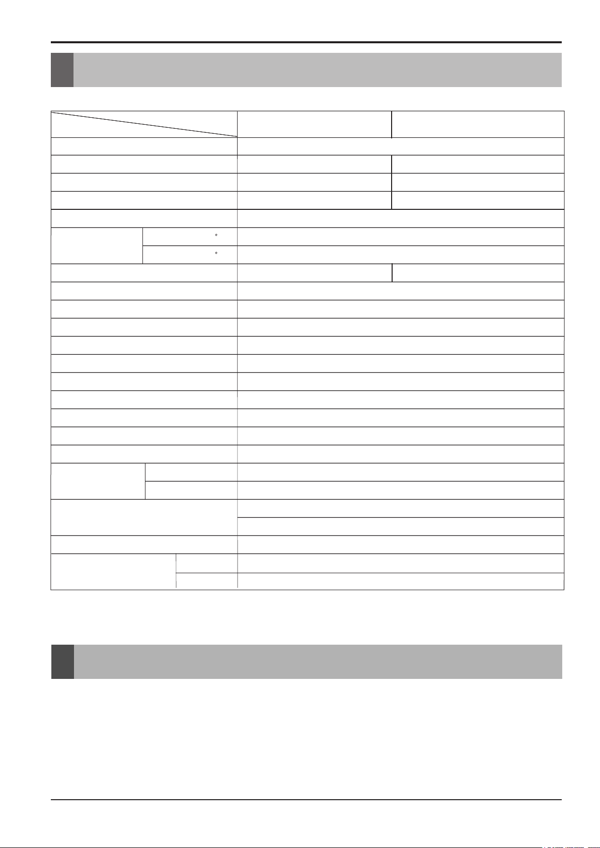
Product Specifications
Operation
• DESIGNED FOR COOLING ONLY
• POWERFUL AND INCREDIBLE COOLING
• TOP-DOWN CHASSIS FOR THE SIMPLE INSTALLATION AND SERVICE
• BUILT-IN ADJUSTABLE THERMOSTAT
• WASHABLE ONE-TOUCH FILTER
• COMPACT SIZE
Product Specifications
Product SpecificationsProduct Specifications
Specfications
MODELS
ITEMS
POWER SUPPLY
COOLING CAPACITY (Btu/h)
INPUT (W)
RUNNING CURRENT (A)
.
E.E.R (BTU/W.h)
OPERATING
CONDITION
REFRIGERANT (R410) CHARGE
EVAPORATOR
CONDENSER
FAN, INDOOR
FAN, OUTDOOR
FAN SPEEDS, FAN/COOLING
FAN MOTOR
OPERATION CONTROL
INDOOR ( F)
OUTDOOR ( F)
.
CP10F10
1Ø , 115, 60Hz
10,000
920
8.5
10.8
80 (DB)* 67(WB)**
95 (DB)* 75(WB)**
530g(18.7oz)
Ø9.52, 2ROW 13STACKS
Ø5 , 3ROW 18STACKS
.0..0
.0
TURBO FAN
PROPELLER TYPE FAN WITH SLINGER RING
3/3
6 POLES
REMOTE CONTROLLER
CP12F10
12,000
1,110
10.2
540g(19.0oz)
ROOM TEMP. CONTROL
AIR DIRECTION CONTROL
CONSTRUCTION
PROTECTOR
POWER CORD
DRAIN SYSTEM
OUTSIDE DIMENSION
(W x H x D)
H x
* DB:Dry Bulb
**
WB:Wet Bulb
COMPRESSOR
FAN MOTOR
(inch)
(mm)
HORIZONTAL LOUVER (UP & DOWN), VERTICAL LOUVER (RIGHT&LEFT)
INTERNAL THERMAL PROTECTOR
ATTACHMENT PLUG (CORD-CONNECTED TYPE)
DRAIN PIPE OR SPLASHED BY FAN SLINGER
380 x 600 x 555
THERMISTOR
SLIDE IN-OUT CHASSIS
OVERLOAD PROTECTOR
3 WIRE WITH GROUNDING
23
5/8
x14
31/32
x22
5/16
Se rvice Manual
Ser 7
Ser
Mode
Fan Only
Fan
Speed
4
3
Cool
Dry
5
Timer
0n/
0
ff
Money Saver
Temp
7
Ai r
P urif ier
Po wer
1
0
F
Auto
Swing
hr
Power
®
5
6
2
6
1
Fa n S pe ed
Ti mer
Auto
Swing
Tem p
Mod e
A
S wing
2
4
3
6. AUTO SWING
This button can automatically control the air flow
direction.
7
Service Manual 8
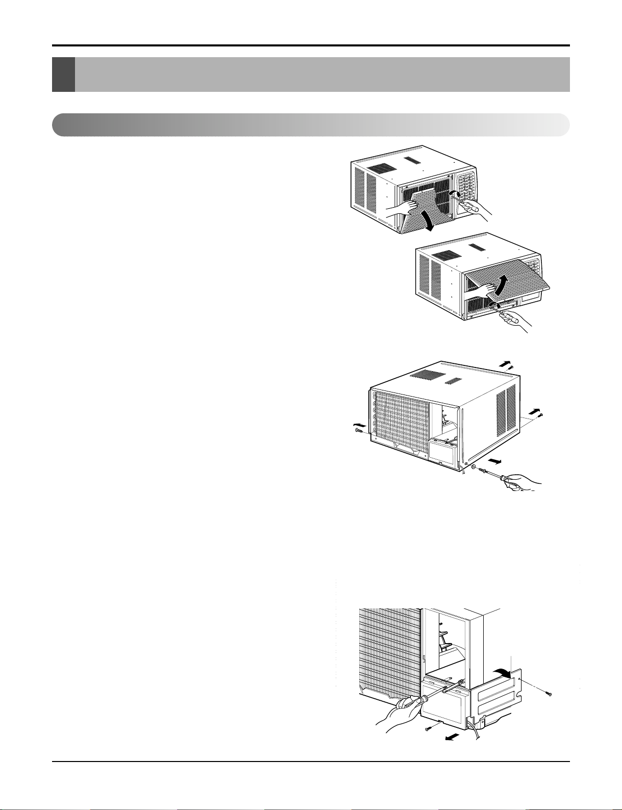
Disassembly
Disassembly
Mechanical Parts
Before the following disassembly, POWER SWITCH set to OFF and disconnect the power cord.
1. FRONT GRILLE
1. Open the lnlet grille upward or downward.
2. Remove the screw which fastens the front grille.
3. Pull the front grille from the right side.
4. Remove the front grille.
5. Re-install the component by referring to the
removal procedure, above.(See Figure 1)
2. CABINET
1. After disassembling the FRONT GRILLE, remove
the 2 screws which fasten the cabinet at both
sides.
2. Remove the 2 screws which fasten the cabinet at
back.
3. Pull the base pan forward. (See Figure 2)
4. Remove the cabinet.
5. Re-install the component by referring to the
removal procedure, above.
3. CONTROL BOX
1. Disconnect the unit from the power source.
2. Remove the front grille.
3. Remove the cabinet.
4. Remove the screw which fastens the control box
cover.
5. Remove the housing which connects motor wire
in the control box.
6. Remove the 3 leads from the compressor.
7.Discharge the capacitor by placing a 20,000
ohmresistor across the capacitor terminals.
8. Remove the 2 screws which fasten the control
box.(See Figure 19)
9. Pull the control box forward completely.
10. Re-install the components by referring to the
removal procedure, above. (See Figure 3)
Figure 1
Figure 3
Figure 2
Service Manual 9