

Friedrich ZQ10, CP08C10, CP08N10, Z-Star ZQ10C10, ZQ08C10 Installation And Operation Manual
...Page 1

ENGLISH FRANÇAIS ESPAÑOL
Room Air Conditioner
Installation and Operation
Manual
MODEL NUMBER SERIAL NUMBER PURCHASE DATE
CP Line
920-151-00 (7-05)
CP08 ZQ08 ZQ10115 Volts
Registering Your Room Air Conditioner
Model information can be found on the name plate located on the
side of the unit near the control panel. Please complete and mail
the owner registration card furnished with this product or register
on-line at www.friedrich.com (USA only). For your future
convenience, record the model information here.
1
Page 2

2
Page 3

ENGLISH
Table of Contents
Introduction ..................................................................................2
Safety Precautions.......................................................................3
How to operate your Friedrich ...................................................5
Adjusting the Air Flow Direction.................................................7
Care and Maintenanc
e.................................................................8
Ha
rdware Location.......................................................................9
Installation Instructions
........................................................
15
Troubleshooting Tips.................................................................17
Warrant
y......................................................................................18
How to operate your Friedrich ZStar ......................................6
Congratulations!
You have purchased a Friedrich
room air conditioner. The Friedrich
units are designed to give maximum
comfort and quietness.
3
Page 4

Before Operating Your Unit
Make sure the wiring is adequate for your unit.
If you have fuses, they should be of the time delay type. Before you install or relocate this unit, be sure that
the amperage rating of the circuit breaker or time delay fuse does not exceed the amp rating listed in figure 1.
DO NOT use an extension cord.
The cord provided will carry the proper amount of electrical power to the unit; an extension cord will not.
Make sure that the receptacle is compatible with the wall plug provided.
This insures proper grounding. If you have a two-prong receptacle you will need to have the circuit replaced
by a certified electrician with a grounded circuit that meets all national and local codes and ordinances. You
must use the three-prong plug furnished with the air conditioner.
Figure 1
For the Best Cooling Performance and Energy Efficiency
Keep the filter clean
Make sure that your air conditioner is always in top performing condition by cleaning the filter regularly.
Instructions for removing and cleaning the filter can be found on page 8.
Provide good airflow
Make sure that the airflow to and from the unit is clear. Your air conditioner puts the air out at the top of
the unit, and takes in air at the bottom. Airflow is critical for good operation. It is just as important on the
outside of the building that the airflow around the unit exterior is not blocked.
Unit Placement
If your air conditioner can be placed in a window or a wall that is shaded by a tree or another building, the
unit will operate even more efficiently. Using drapes or blinds on the sunny side of the dwelling will also
add to your unit's efficiency.
Insulation
Good insulation will be a big help in maintaining desirable comfort levels. Doors should have weather
stripping. Be sure to caulk around doors and windows.
2
Introduction
MODEL
AMP VOLT NEMA NO.
15 125 5-15P
CIRCUIT
RATING OR
TIME DELAY
FUSE
PLUG FACE
CP08 ZQ08 ZQ10
4
Page 5
ENGLISH
3
Safety Precautions
To prevent injury and property damage, follow these instructions.
■ Incorrect operation due to ignoring of instruction can cause harm or damage. The seriousness is classified
by the following indications.
WARNING This symbol indicates the possibility of death or serious injury.
CAUTION
This symbol indicates the possibility of injury or damage to
properties only.
■ Meanings of symbols used in this manual are as shown below.
Never Do This
Always Do This
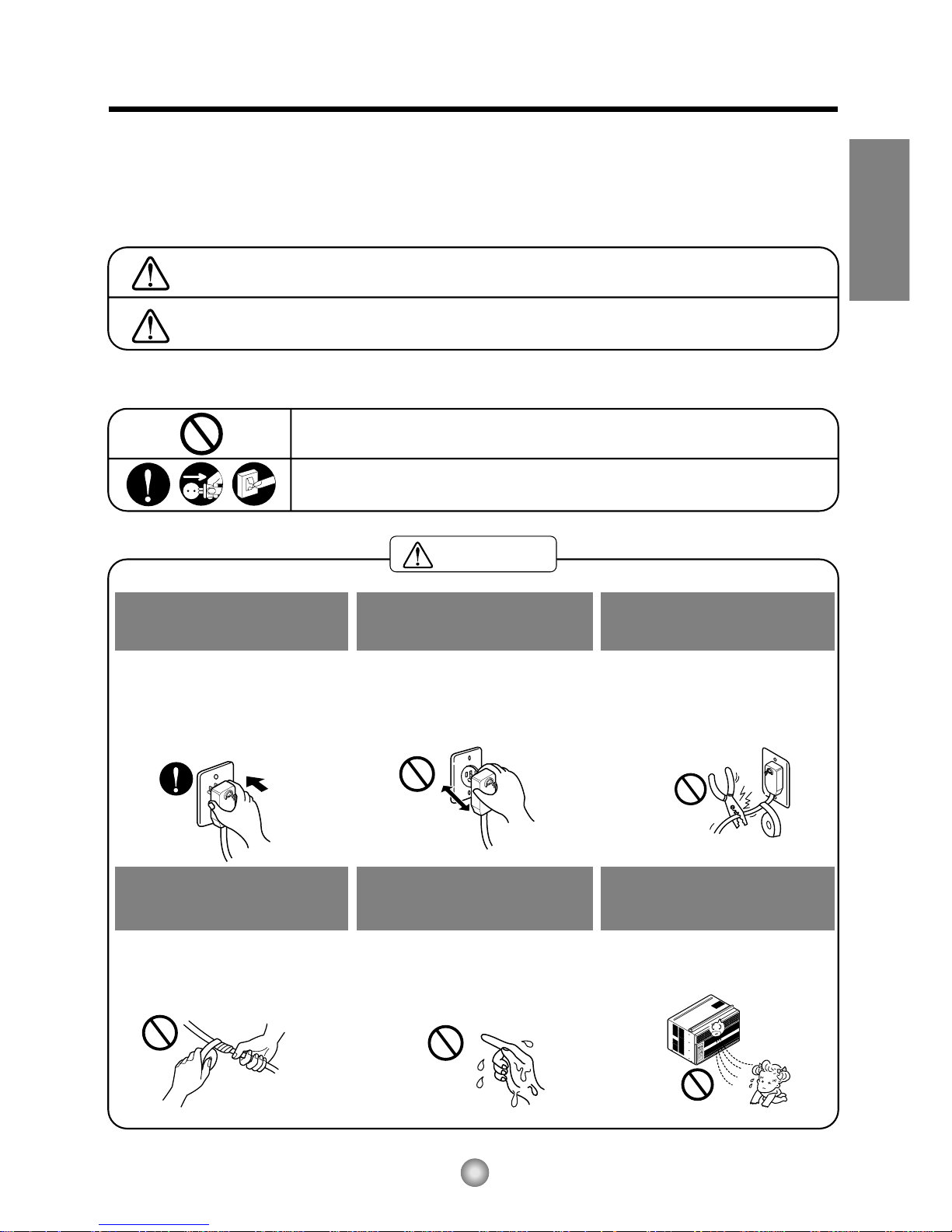
WARNING
Plug in the power plug
properly.
• Otherwise, it will cause electric
shock or fire due to heat
generation.
Do not operate or stop the
unit by inserting or pulling
out the power plug.
• It will cause electric shock or fire
due to heat generation.
Do not damage or use an
unspecified power cord.
• It will cause electric shock or fire.
•
If the power cord is damaged, it must
be replaced by the manufacturer or a
Friedrich-certified service agent.
Do not modify power cord
length.
• It will cause electric shock or fire
due to heat generation.
Do not operate with wet
hands or in damp
environment.
• It will cause electric shock.
Do not direct air flow directly
at room occupants.
•
This could lead to health problems
.
5
Page 6

4
T
I
M
E
M
O
D
E
T
E
M
P
P
O
W
E
R
F
A
N
S
P
E
E
D
T
I
M
E
M
O
D
E
T
E
M
P
P
O
W
E
R
F
A
N
S
P
E
E
D
Sharp
edges
When the air filter is to be
removed, do not touch the
metal parts of the unit.
• They are sharp and may cause
an injury.
Do not clean the air
conditioner with water.
• Water may enter the unit and
degrade the insulation. It may
cause an electric shock.
When the unit is to be
cleaned, switch the unit off,
and unplug it.
• Since the fan rotates at high
speed during operation, it may
cause an injury.
Do not operate the unit
without the air filter or when
the front intake grille has
been removed.
• It could cause dust to
accumulate on the heat
exchanger.
Do not put a pet or house
plant where it will be
exposed to direct air flow.
• This could injure the pets
or plants.
Do not use for special
purposes.
• Do not use this air conditioner to
preserve precision devices, food,
pets, plants, and art objects.
It may cause deterioration of
quality, etc.
Do not operate switches
with wet hands
.
• It may cause an electric shock.
Do not apply an insecticide
or flammable spray.
• It may cause a fire or
deformation of the cabinet.
SHARP EDGES!
The edges of the case can
be SHARP!
• Use caution when handling the
case. Grip it firmly and do not allow
it to slip while holding it.
•
Use heavy gloves to handle
the case if necessary.
•
DO NOT
allow the
case to slide
against
your skin!
6
Page 7

ENGLISH
5
How to operate your Friedrich
Power
Temp
Fan Speed
Timer Mode
1
2
3
4
5
1
2
453
6
Control and Remote Control Operations
1. POWER
Operation begins when this button is pressed
and stops when you press the button again.
2. TEMPERATURE CONTROL
The thermostat monitors room temperature
to maintain the desired temperature.
The thermostat can be set between
60°F~86°F (16°C~30°C).
The unit takes an average of 30 minutes to
adjust the room temperature by 1°F.
3. OPERATION MODE SELECTOR
Select cooling mode to cool the room.
Select Money Saver® mode for energy
saving operation.
Select fan mode for basic ventilating fan
operation.
Select dry mode for dry operation.
4. FAN SPEED SELECTOR
For increased power while cooling, select a
higher fan speed.
3 steps: High; Low; Med
5. ON/OFF TIMER
The timer can be set to start and stop the
unit in hourly increments (up to 12 hours).
6. REMOTE CONTROL SENSOR
Inserting the Remote Control Batteries
1. Push out the cover on the back
of the remote control with your
thumb
2. Pay attention to polarity and
insert two new AAA 1.5V
batteries.
3. Reattach the cover.
NOTE:
Do not use rechargeable batteries. Make sure that
both batteries are new.
• In order to prevent discharge, remove the batteries from
the remote control if the air conditioner is not going to be
used for an extended period of time
Keep the remote control away from extremely hot or
humid places.
To maintain optimal operation of the remote control, the
remote sensor should not be exposed to direct sunlight.
• The remote control can be mounted on a wall using the
mountable holder.(Friedrich does not provide this.)
7
Page 8

6
How to operate your Friedrich ZStar
®
Function Controls
When the air conditioner has finished cooling the room and is turned off or set to the fan
position, wait at least 3 minutes before resetting to the cooling operation again.
CAUTION
HIGH
COOL
HIGH
COOL
MED
FAN
MED
FAN
LOW
FAN
LOW
FAN
LOW COOLLOW COOL
MED
COOL
MED
COOL
11
99
88
22
77
33
66
44
55
Off - Turns air conditioner off.
Med Fan - Med speed fan operation without cooling.
Low Fan - Low speed fan operation without cooling.
High Cool - Cooling with high speed fan operation.
Med Cool - Cooling with med speed fan operation.
Low Cool - Cooling with low speed fan operation.
This automatically controls the temperature of the indoor air.
Turn the knob so that arrow points to the higher number for greater cooling.
Point the arrow to the lower number for more moderate cooling.
(i.e. the higher the number, the greater the cooling)
• FOR NORMAL COOLING
1. Turn the operation switch to the High Cool or the Low Cool setting.
2. Set the Thermostat control to the desired temperature mark 5 (the mid-point is a good starting position).
If the room temperature is not satisfactory after a reasonable time, adjust the control to a cooler or warmer
setting, as appropriate.
• FOR MAXIMUM COOLING
1. Turn the Operation Knob to the High Cool setting.
2. Set the Thermostat control to the largest (9) temperature mark.
• FOR QUIETER OPERATION
1. Turn the Operation Knob to the Low Cool setting.
2. Set the Thermostat control as needed.
8
Page 9

7
VENTCLOSE
OPEN
Part
A
Adjusting the Air Flow Direction
Vent Control
For maximum cooling efficiency, CLOSE the vent. This will allow internal air circulation.
OPEN the vent to discharge stale air.
NOTE : Before using the ventilation feature, position
the vent lever by pulling Part A out straight
and snapping it into place.
Adjusting the Air Flow Direction
Airflow can be adjusted by changing the direction of the air conditioner's louvers.
• Adjusting Horizontal Air Flow Direction
Adjusting the vertical louvers left and right will
change horizontal airflow.
• Adjusting Vertical Air Flow Direction
Adjusting the horizontal louver up and down will
change vertical airflow. The louver can be
adjusted by pressing in at the top or button of the
horizontal louver.
Adjusting horizontal air flow Adjusting vertical air flow
• Recommended orientation of louvers
Adjust louvers to face upwards when cooling to maximize cooling efficiency.
ENGLISH
9
Page 10

8
Drain pipe
Drain cap
Care and Maintenance
Turn the power off and unplug the power plug before cleaning the air conditioner.
Air Filter
The air filter behind the inlet grille should be checked and cleaned at least once every 2 weeks (or as
necessary) to maintain optimal performance of the air conditioner.
How to remove the air filter
1. The grille may be opened from the top for easy
maintenance after installation.
2. Open the inlet grille by pulling out on the exposed
door on the top of the unit (based on installation).
3. Pull the tab slightly to release the filter. Pull the
filter in the same direction as the opening.
4. Clean the filter with warm, soapy water.
5. Rinse off and gently shake off excess water from
the filter. Make sure filter is completely dry before
replacing it.
Drainage
The base pan may overflow due to high humidity. To drain
the excess water, remove the drain cap from the back of
the unit and secure the drainpipe.
When pressing the drainpipe into place, apply force in the
direction away from the fins to avoid injuring yourself.
10
Page 11

9
8
4
5
1
2
3
B
A
Power cord
Power cord
7
13
11
14
12
10
6
9
15
Hardware Location
Product Features
Positioning the Power cord
CAUTION
This appliance should be installed in accordance with local and national wiring regulations. This
manual acts as a guide to help to explain product features.
1. CABINET
2. FRONT GRILLE
3. AIR FILTER
4. AIR INTAKE (INLET GRILLE)
5. AIR DISCHARGE
6. VERTICAL AIR DEFLECTOR
(HORIZONTAL LOUVER)
7. EVAPORATOR
8. HORIZONTAL AIR DEFLECTOR
(VERTICAL LOUVER)
9. CONTROL PANEL
10. POWER CORD
11. COMPRESSOR
12. BASE PAN
13. BRACE
14. CONDENSER
15. REMOTE CONTROLLER
You can choose between two methods below according to your window stool shape and preference.
• Fasten the stopper using 2 screw holes, and lead
out the power cord through slit "A".
• Fasten the stopper using left screw hole, and rotate
properly to lead the power cord out through slit "B".
Using slit "A" Using slit "B"
ENGLISH
11
Page 12

10
22" to 36"
Offset
1
/2" to 11/4"
Sill
Exterior
Interior wall
20
1
/12" min.
(Without frame curtain)
Stool
15" min
(With frame curtain)
About
1
/2"
30"~60"
Awning
Cooled air
Fence
Over 20"
Heat
radiation
How to Install the Unit
1. To prevent vibration and excess noise,
make sure the unit is installed securely
and firmly
2. Install the unit where the sunlight does not
shine directly on the unit.
3. The outside of the cabinet must extend
outward for at least 12" and there should
be no obstacles, such as a fence or wall,
within 20" from the back of the cabinet, as
it will prevent heat radiation of the
condenser.
Restriction of outside air will greatly reduce
the cooling efficiency of the air conditioner.
CAUTION: All side louvers of the cabinet must remain exposed and unobstructed to the outside of the
structure.
4. Install the unit with a rear, downward slope, so the back is slightly lower than the front
(about 1/4" buble on a level). This will force condensation to flow to the outside.
5. Install the unit with the bottom about 30"~60" above the floor level.
Window Requirements
NOTE: All supporting parts should be secured to firm wood, masonry, or metal.
• This unit is designed for installation in standard
double hung windows with actual opening widths
from 22" to 36".
• The top and bottom window sash must open
sufficiently to allow a clear vertical opening of 15"
from the bottom of the upper sash to the window
stool.
12
Page 13

11
ENGLISH
1
2 3 4
8
10
9
13
765
12
11
13
Shipping
Screws
(Type A)
(Type A)
5
11
11
5
5
9
Installation Kit Contents
NO. NAME OF PARTS Q'TY
1 FRAME CURTAIN 2
2 SILL SUPPORT 2
3 BOLT 2
4 NUT 2
5 SCREW (TYPE A) 16
6 SCREW (TYPE B) 3
7 SCREW (TYPE C) 5
8 FOAM-STRIP 1
9 UPPER GUIDE 1
10 FOAM-PE 1
11 FRAME GUIDE 2
12 WINDOW LOCKING BRACKET 1
13 FOAM-PE 1
Suggested Tool Requirements
SCREWDRIVER(+, -), RULER, KNIFE, HAMMER, PENCIL, LEVEL
PREPARATION OF CHASSIS
1. Remove the screws which fasten the cabinet at both
sides and at the back.(4 total)
2. Slide the unit from the cabinet by gripping the base pan
handle and pulling forward while bracing the cabinet.
3. Cut the window sash seal to the proper length.
Peel off the backing and attach the Foam-PE to the
underside of the window sash.
4. Remove the backing from the top upper guide Foam-PE
and attach it to the bottom of the Upper Guide .
5. Attach the upper guide onto the top of the cabinet with 3
Type A screws .
6. Insert the Frame Guides into the bottom of the cabinet.
7. Insert the Frame Curtain into the Upper Guide and
Frame Guides .
8. Fasten the curtains to the unit with 4-Type
A screws .
Page 14

12
INDOOR OUTDOOR
Sill Support
2
Nut
4
Bolt
3
INDOOR OUTDOOR
Cabinet
About
1
/2"
Frame Guide
11
Screw(Type A)
5
Upper Guide
Window stool
Front Angle
Window Sash Upper guide
Frame Curtain
1
Foam-pe
Foam-pe
13
Cabinet
Fig. 1
Fig. 2
Fig. 3
Fig. 4
Cabinet Installation
1. Open the window. Mark a line on center of the
window stool.
Carefully place the cabinet on the window
stool and align the center mark on the bottom
front with the center line marked in the
window stool.
2. Pull the bottom window sash down behind the
Upper Guide until they meets.
NOTE: Do not pull the window sash down so
tightly that the movement of Frame
Curtain is restricted.
3. Loosely assemble the Sill Support using
the parts in Fig. 3.
4. Select the position that will place the Sill
Support near the outer most point on sill
(See Fig. 4)
NOTE: Be careful when you install the cabinet
(Frame Guides are broken easily).
5. Attach the Sill Support to the cabinet track
hole in relation to the selected position using
2 -type A screws in each support
(See Fig. 4).
14
Page 15
13
Sash track
Front Angle
About
1
/2"
Screw(Type B)
6
Screw(Type B)
6
Sill Support
2
Sill Support
2
Foam-Strip
8
Fig. 5
Type C
7
Fig. 6
Screw(Type A)
Screw
(Type A)
Power cord
Fig. 7
Fig. 8
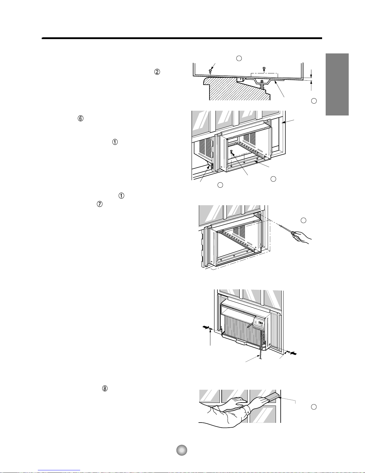
6. The cabinet should be installed with a very slight
tilt (about 1/2") downward toward the outside
(See Fig. 5).
Adjust the bolt and the nut of Sill Support for
balancing the cabinet.
7. Attach the cabinet to the window stool by driving
the screws [Type B: Length 16mm (5/8 inch)
and below.] through the front angle into window
stool.
8. Pull each Frame Curtain to each window
sash track, and repeat step 2.
9. Attach each Frame Curtain to the window
sash using screws (Type C). (See Fig. 6)
CAUTION: Do not drill a hole in the bottom pan.
The unit is designed to operate with
approximately 1/2" of water in bottom
of pan.
There is no need to add water if the
pan is dry.
10. Slide the unit into the cabinet. (See Fig. 7)
CAUTION: For security purpose, reinstall the 2
screws (Type A) at cabinet's side, that
were removed in step 1 on page 10.
11. Cut the Foam-Strip to the proper length
(window width) and insert between the upper
window sash and the lower window sash.
(See Fig. 8)
ENGLISH
15
Page 16

14
Window locking
bracket
12
Fig. 9
Fig. 10
Fig. 11
12. Attach the Window Locking Bracket with a Type C
screw . (See Fig. 9)
13. Attach the front grille to the cabinet by inserting the
tabs on the grille into the tabs on the front of the
cabinet. Push the grille in until it snaps into place. (See
Fig. 10)
14. Pull down the inlet grille and secure it with a Type A
screw through the front grille. (See Fig. 11)
15. Window installation of room air conditioner is now
completed. See ELECTRICAL DATA for
inserting power cord to electrical outlet.
16
Page 17

15
NOTE TO INSTALLER: Leave these
instructions with the air conditioner after
installation is completed.
NOTE TO CONSUMER: Keep this Installation
and Operation Manual for future use.
Important notes:
It is recommended that proper attire be worn
during installation.
For personal safety, this air conditioner must
be properly grounded.
It is important to have the wall outlet and circuit
checked by a qualified electrician if there is any
doubt as to whether a proper ground exists.
CAUTION:
Do not under any circumstances, cut or remove
the third (ground) prong from the power cord.
Do not change the plug on the power cord o f
this a ir conditioner.
Aluminum ho use w iring may present special
problemsÐconsult a qu alif ied electricia n.
Before You Begin
Read these instructions completely and carefully.
Installation Instructions
Phillips-head screwdriver
Flat-blade screwdriver
Ruler or tape measure
Scissors or knife
Pencil
Level
Hammer
Tools You Will Need
ENGLISH
17
Page 18

115V~
Power cord may include a current
interrupter device. A test and reset button is
provided on the plug case. The device
should be tested on a periodic basis by first
pressing the TEST button and then the
RESET button. If the TEST button does not
trip or if the RESET button will not stay
engaged, discontinue use of the air
conditioner and contact a qualified service
technician.
Use of extension cords
Because of potential safety hazards , we strongly discourage the use of an extension cord. However,
if you wish to use an extension cord, use a CSA certified/UL-listed3-wire (grounding) extension cord, rated 15A,
125V.
All wiring should be made in accordance with local electr ical codes and regulations.
Aluminum house wiring may pose special problems. Consult a qualified electrician.
NOTICE
ELECTRICAL SAFETY
IMPORTTANT GROUNDING INSTRUCTIONS
Air conditioner has a three-prong grounding plug on its power supply cord, which must be plugged into
properly grounded three-prong wall receptacle for your protection against possible shock hazard.
Electrical Safety
Electrical Safety
Electrical Safety
Electrical Safety
Electrical DataElectrical Data
115V~
Power cord may include a current
interrupter device. A test and reset button is
provided on the plug case. The device
should be tested on a periodic basis by first
pressing the TEST button and then the
RESET button. If the TEST button does not
trip or if the RESET button will not stay
engaged, discontinue use of the air
conditioner and contact a qualified service
technician.
Use Wall Receptacle Power Supply
Standard 125V, 3-wire grounding
receptacle rated 15A, 125V AC
Use 15 AMP. time
delay fuse or 15 AMP.
circuit breaker.
16
18
Page 19

17
Troubleshooting Tips
Troubleshooting Tips save time and money! Review the chart below first and you may not need to call for
service.
Normal Operation
You may hear a pinging noise caused by water being picked up and thrown against the condenser
on rainy days or when the humidity is high. This design feature helps remove moisture and improve
efficiency.
You may hear the thermostat click when the compressor cycles on and off.
Water will collect in the base pan during high humidity or on rainy days. The water may overflow and
drip from the outdoor side of the unit.
The fan may run even when the compressor does not.
Your air conditioner is designed to cool in warm weather when the outside temperature is above
60 F(16 C) and below 115 F(46 C).
Abnormal Operation
ENGLISH
19
Page 20

18
FRIEDRICH AIR CONDITIONING CO.
Post Office Box 1540 • San Antonio, Texas 78295-1540
(210) 357-4400 • FAX (210) 357-4490
ROOM AIR CONDITIONERS
LIMITED WARRANTY
FIRST YEAR
SECOND THROUGH FIFTH YEAR
Revised 08/01
1. Air filters or fuses.
2. Products on which the model and serial numbers have been removed.
3. Products which have defects or damage which results from improper installation, wiring, electrical current characteristics, or
maintenance; or caused by accident, misuse or abuse, fire, flood, alterations and/or misapplication of the product and/or units
installed in a corrosive atmosphere, default or delay in performance caused by war, government restrictions or restraints, strikes,
material shortages beyond the control of FRIEDRICH, or acts of God.
ANY PART: If any part supplied by FRIEDRICH fails because of a defect in workmanship or material within twelve months from date of
original purchase, FRIEDRICH will repair the product at no charge, provided room air conditioner is reasonably accessible for service.
Any additional labor cost for removing inaccessible units and/or charges for mileage related to travel by a Service Agency that exceeds
25 miles one way will be the responsibility of the owner. This remedy is expressly agreed to be the exclusive remedy within twelve
months from the date of the original purchase.
SEALED REFRIGERANT SYSTEM: If the sealed refrigeration system (defined for this purpose as the compressor, condenser coil,
evaporator coil, reversing valve, check valve, capillary, filter drier, and all interconnecting tubing) supplied by FRIEDRICH in your Room
Air Conditioner fails because of a defect in workmanship or material within sixty months from date of purchase, FRIEDRICH will pay a
labor allowance and parts necessary to repair the Sealed Refrigeration System; PROVIDED FRIEDRICH will not pay the cost of diagnosis
of the problem, removal, freight charges and transportation of the air conditioner to and from the Service Agency, and the reinstallation
charges associated with repair of the Sealed Refrigeration System. All such cost will be the sole responsibility of the owner. This remedy
is expressly agreed to be the exclusive remedy within sixty months from the date of the original purchase.
APPLICABILITY AND LIMITATIONS:
This warranty is applicable only to units retained within the Fifty States of the U.S.A., District of
Columbia, and Canada. This warranty is not applicable to:
OBTAINING WARRANTY PERFORMANCE: Service will be provided by the FRIEDRICH Authorized Dealer or Service Organization
in your area. They are listed in the Yellow Pages.If assistance is required in obtaining warranty performance, write to: Room Air Conditioner
Service Manager, Friedrich Air Conditioning Co., P.O. Box 1540, San Antonio, TX 78295-1540.
LIMITATIONS: THIS WARRANTY IS GIVEN IN LIEU OF ALL OTHER WARRANTIES. Anything in the warranty notwithstanding,
ANY IMPLIED WARRANTIES OF FITNESS FOR PARTICULAR PURPOSE AND/OR MERCHANTABILITY SHALL BE LIMITED TO
THE DURATION OF THIS EXPRESS WARRANTY. MANUFACTURER EXPRESSLY DISCLAIMS AND EXCLUDES ANY LIABILITY
FOR CONSEQUENTIAL OR INCIDENTAL DAMAGE FOR BREACH OF ANY EXPRESSED OR IMPLIED WARRANTY.
NOTE:
Some states do not allow limitations on how long an implied warranty lasts,or do not allow the limitation or exclusion of consequential
or incidental damages,so the foregoing exclusions and limitations may not apply to you.
OTHER: This warranty gives you specific legal rights, and you may also have other rights which vary from state to state.
PROOF OF PURCHASE: Owner must provide proof of purchase in order to receive any warranty related services.
All service calls for explaining the operation of this product will be the sole responsibility of the consumer.
All warranty service must be provided by an Authorized FRIEDRICH Service Agency, unless authorized by FRIEDRICH prior to
repairs being made.
In case of questions regarding the provisions of this warranty, the English version will govern.
20
Page 21

FRANÇAIS
CP Line
920-151-00 (01/03)
Manuel d'utilisation
et d'installation
de votre climatiseur de pièce
NUMÉRO DU MODÈLE NUMÉRO DE SÉRIE DATE D'ACHAT
Enregistrement de votre climatiseur de pièce
Vous trouverez l'information concernant l'appareil sur la plaque signalétique
située sur le côté de l'appareil, près du panneau de commande. Veuillez
remplir et poster la carte d'enregistrement fournie avec l'appareil ou
enregistrez-vous en ligne à www.friedrich.com (USA uniquement). Veuillez
consigner l'information à l'emplacement ci-dessous pour référence ultérieure.
CP08 ZQ08 ZQ10115 Volts
21
Page 22

22
Page 23

FRANÇAIS
Félicitations !
Vous avez fait l'achat d'un climatiseur de
pièce de Friedrich. Friedrich est conçu pour
offrir un maximum de confort et de douceur
de fonctionnement.
Table des matières
Introduction
Mesures de sécurité....................................................................
Fonctionnement de la télécommande........................................5
.3
..................................................................................2
Réglage de l'orientation du débit d'air .......................................7
Soins et entretien.........................................................................8
Installation du matériel................................................................9
Guide d'installation....................................................................15
Problèmes fréquents et solutions ............................................17
Garantie.......................................................................................18
Mode de fonctionnement de votre ZStar par Friedrich .......6
23
Page 24

2
Introduction
Avant d'utiliser votre appareil
Assurez-vous que votre câblage électrique est conforme aux normes de
fonctionnement de l'appareil.
Si votre système électrique comporte des fusibles, veillez qu'ils soient de type temporisé. Avant d'installer ou
de déplacer l'appareil, veillez que l'intensité de courant du disjoncteur ou du fusible temporisé n'excède pas
l'intensité de courant spécifiée à la figure 1.
N'UTILISEZ JAMAIS un fil de rallonge.
Contrairement au cordon d'alimentation fourni avec l'appareil, le fil de rallonge n'acheminera pas le courant
d'alimentation approprié au bon fonctionnement de l'appareil.
Veillez à ce que la prise murale soit compatible avec la fiche du cordon
d'alimentation de l'appareil.
Cela assure la mise à la terre appropriée. Si vous possédez un réceptacle à deux broches, vous devrez le
remplacer par un réceptacle conforme à tous les codes et règlements nationaux ou municipaux. Vous devez
utiliser la fiche à trois broches fournie avec votre climatiseur.
Figure 1
Pour obtenir le meilleur rendement énergétique et de refroidissement
Maintenez le filtre propre
Afin de maintenir le rendement de votre climatiseur à son meilleur niveau, nettoyez régulièrement le filtre.
Reportez-vous à la page 8 pour les instructions de dépose et de nettoyage du filtre.
Veillez à la présence d'une circulation d'air appropriée.
Assurez-vous que l'air circule librement vers et en provenance de l'appareil. Votre climatiseur aspire l'air à
sa surface inférieure et l'évacue à sa surface supérieure. La circulation d'air est un facteur important au
bon fonctionnement de l'appareil. La libre circulation de l'air est également importante
pour la portion de l'appareil située à l'extérieur de l'immeuble.
Emplacement de l'appareil
Votre climatiseur fonctionnera plus efficacement si vous l'installez dans une fenêtre ou dans un mur
situé à l'ombre d'un arbre ou d'un autre immeuble. L'utilisation de rideaux ou stores du côté ensoleillé de
l'immeuble améliorera également le rendement de l'appareil.
Isolation
Une bonne isolation permettra de maintenir le niveau de confort souhaité. Les portes devraient
comporter un calfeutrage adéquat. Veillez à bien calfeutrer le périmètre des portes et fenêtres.
MODÈLE
AMP VOLT
NO. NEMA
(National Electrical Manufacturers Association)
15 125 5-15P
VALEUR NOMINALE OU
TEMPORISATION DU
CIRCUIT
FUSIBLE
TYPE DE FICHE
CP08 ZQ08 ZQ10
24
Page 25

FRANÇAIS
3
Mesures de Sécurité
Pour éviter des accidents corporels ou des dommages matériels, suivez ces instructions.
■
Un mauvais fonctionnement dû à l’ignorance de ces instructions peut provoquer des préjudices corporels
ou des dommages.
AVERTISSEMENT
Ce symbole signale un risque de blessure grave, voire mortelle.
ATTENTION
Ce symbole signale un risque limité aux dommages matériels.
■ Les significations respectives des symboles utilisés dans ce manuel sont indiquées ci-dessous.
Ne faites jamais cela
Faites toujours cela
AVERTISSEMENT
Veillez à brancher
correctement votre appareil
• Tout mauvais branchement peut
entraîner une surchauffe de votre
appareil et causer électrocution
ou incendie.
Veuillez ne pas mettre en
marche ou éteindre votre
appareil en branchant ou
débranchant votre appareil
• Ceci provoquera une surchauffe
et un risque d'électrocution ou
d'incendie.
Evitez d'endommager le
cordon d'alimentation
électrique ou d'en utiliser un
non-agéé
• Ceci pourrait causer
électrocution ou incendie.
Ne modifiez pas la longueur du
cordon d'alimentation et ne
branchez pas votre climatiseur
en commun avec d'autres
appareils sur la même prise
• Ceci pourrait provoquer un
électrique ou un incendie, dû à
une surchauffe.
Ne faites pas fonctionner
l'appareil les mains
mouillées.
• II y a risque d'électrocution.
Ne dirigez pas directement le
flux d’air sur les occupants
de la pièce.
• Ceci pourrait mener au problème
de santé.
25
Page 26

4
T
I
M
E
M
O
D
E
T
E
M
P
P
O
W
E
R
F
A
N
S
P
E
E
D
T
I
M
E
M
O
D
E
T
E
M
P
P
O
W
E
R
F
A
N
S
P
E
E
D
Bords
pointus
ATTENTION
Lorsque le filtre à air doit
être retiré, ne pas toucher les
parties métalliques de
l'appareil.
• Vous risquez de vous blesser.
Ne pas nettoyer le
climatiseur avec de l'eau.
• L'eau peut s'infiltrer dans
l'appareil et affecter l'isolement.
Cela peut également provoquer
un choc électrique.
Quand l'unité devrait être
nettoyée, change l'unité de, et le
débrancher.
• Le ventilateur de refroidissement
tournant à grande vitesse dans
l'appareil, cela peut provoquer un
accident.
Ne pas opérer l'unité sans le
filtre à air ou quand le
grillage frontal a été enlevé.
• De la poussière pourrait
s'accumuler sur l'échangeur
thermique.
Ne pas placer une plante
d'intérieur ou un animal
domestique près de l'appareil
en risquant de l'exposer
directement à l'air froid.
• L'animal comme la plante
peuvent en souffrir.
Ne pas se servir de l'appareil
à des fins spéciales.
•
Le climatiseur ne doit pas être utilisé pour
protéger certains appareils de précision, des
aliments, des animaux, des plantes et des
objets d'art. La qualité risque d'en souffrir.
Ne pas actionner les
dispositifs de commande les
mains mouillées.
• Il y a risque de choc électrique.
Ne pas utiliser d'insecticide à
proximité de l'appareil ni de
produits inflammables.
• L'appareil risque de prendre feu
ou le coffret risque d'être
déformé.
BORDS POINTUS!
Les bords du cas peuvent être
pointus!
• Faites attention en manipulant le boîtier.
Saisissez le boîtier fermement et ne le
laissez pas glisser tout en le tenant.
•
Employez les gants lourds pour manipuler
le boîtier au besoin.
• Ne laissez pas
le boîtier
glisser contre
votre peau!
26
Page 27

FRANÇAIS
5
Fonctionnement de la télécommande
Power
Temp
Fan Speed
Timer Mode
1
2
3
4
5
1
2
453
6
Fonctionnement de la télécommande
1. POWER
Appuyez sur cette touche pour activer l'appareil
et appuyez de nouveau pour le désactiver.
2. CONTRÔLE DE TEMPÉRATURE
Le thermostat surveille la température de la
pièce afin d'y maintenir la température souhaitée.
Vous pouvez régler le thermosat entre
60°F~86°F (16°C~30°C).
Cet appareil ne requiert qu'environ 30 minutes
pour changer la température de la pièce de 1°F.
3.
SÉLECTEUR DE MODE DE
FONCTIONNEMENT
Rafraîchissez la pièce à l'aide du mode de refroidissement.
Pour le fonctionnement en mode d'économie énergétique,
sélectionnez le mode économiseur d'énergie.
Pour le fonctionnement normal du ventilateur,
sélectionnez le mode ventilateur.
Pour la déshumidification, sélectionnez le mode
sans humidité.
4. SÉLECTEUR DE RÉGIME DU VENTILATEUR
Pour un refroidissement accru, réglez le
ventilateur à un régime supérieur.
3 niveaux : High; Low; Med
5. MINUTERIE ACTIVATION/DÉSACTIVATION
La minuterie peut être réglée pour
l'activation/désactivation de l'appareil à
intervalles de une heure (jusqu'à 12 heures).
6. CAPTEUR DE SIGNAL DE TÉLÉCOMMANDE
Remplacement des piles de la télécommande
1. Retirez le couvercle situé à l'arrière
de la télécommande avec votre
pouce.
2. Notez la polarité des piles et
insérez deux piles AAA 1,5V
neuves.
3. Replacez le couvercle.
NOTE : N'utilisez pas de piles rechargeables.
Remplacez les deux piles à la fois.
• Si vous ne prévoyez pas utiliser le climatiseur pour une
longue période de temps, retirez les piles de la
télécommande. Assurez-vous de remiser la
télécommande à l'écart des endroits excessivement
chauds ou humides. Pour vous assurer du meilleur
rendement possible de votre télécommande, protégez le
capteur de télécommande des rayons directs du soleil.
• Votre télécommande peut être monté au mur à l'aide du
dispositif spécial de support.
27
Page 28

6
Mode de fonctionnement de votre ZStar par Friedrich
Les commandes ressembleront à celles illustrées ci-dessous.
Commandes de fonctionnement
ATTENTION
Lorsque la pièce est suffisamment rafraîchie et que vous arrêtez le climatiseur ou que vous réglez
le ventilateur à une certaine vitesse, patientez au moins 3 minutes avant de lancer un nouveau cycle
de refroidissement.
HIGH
COOL
HIGH
COOL
MED
FAN
MED
FAN
LOW
FAN
LOW
FAN
LOW COOLLOW COOL
MED
COOL
MED
COOL
11
99
88
22
77
33
66
44
55
Off (Fermé) : Met le climatiseur hors tension.
Med Fan (Ventilateur moyen) : Fait fonctionner le ventilateur à vitesse
moyenne, sans refroidissement.
Low Fan (Ventilateur bas) : Fait fonctionner le ventilateur à basse
vitesse, sans refroidissement.
High Cool (Refroidissement haut) : Refroidit tout en ventilant à haute vitesse.
Med Cool
(Refroidissement moyen)
:
Refroidit tout en ventilant à vitesse moyenne.
Low Cool (Refroidissement bas) : Refroidit tout en ventilant à basse vitesse.
Cette fonction contrôle automatiquement la température de l'air
ambiant. Tournez le bouton en direction des chiffres les plus
grands pour un refroidissement plus puissant. Faites-le pointer
vers les petits chiffres si vous désirez une ambiance moins fraîche.
Plus le chiffre est élevé, plus le refroidissement est puissant.
(i.e. le plus haut le numéro, le plus grand le refroidir)
POUR UN REFROIDISSEMENT NORMAL
1. Tournez le bouton des fonctions "Operation" à la position de refroidissement élevé "High Cool" ou de
refroidissement faible "Low Cool".
2. Réglez le thermostat à la température désirée 5 (la position du milieu est un bon point de départ). Si la
température ambiante n'est pas satisfaisante après un certain temps, ajustez la position à un degré plus
froid ou plus chaud, au besoin.
POUR UN REFROIDISSEMENT MAXIMAL
1. Tournez le bouton des fonctions "Operation" à la position de refroidissement élevé "High Cool".
2. Réglez le themostat à la position la plus froide, représentée par le plus grand (9) des chiffres.
POUR UN FONCTIONNEMENT PLUS SILENCIEUX
1. Tournez le bouton des fonctions "Operation" au réglage de refroidissement faible "Low Cool".
2. Réglez le thermostat à la température voulue.
28
Page 29

7
A
FERMÉ VENTILATION OUVERT
Pièce
Réglage de l'orientation du débit d'air
Commande de l’orifice de ventilation
Pour une efficacité maximum du refroidissement, fermez l'ORIFICE DE VENTILATION. Ceci activera
la circulation de l'air de la pièce. OUVREZ l'orifice de ventilation afin d'évacuer l'air vicié.
NOTE : Avant d'utiliser le dispositif de ventilation, positionnez le
levier de commande en tirant tout droit sur la pièce A et
en la cliquant en place.
Réglage de l’orientation du débit d’air
Vous pouvez régler le débit d'air en changeant l'orientation des volets du climatiseur.
•
Réglage de l'orientation horizontale du débit d'air
Le réglage des volets verticaux vers la gauche et
la droite changera l'orientation du débit d'air
horizontal.
•
Réglage de l'orientation verticale du débit d'air
Quand vous réglez le louvre horizontal vers le
haut et vers le bas, vous changez le flux d’air
vertical. Le louvre peut être réglé en appuyant
sur le sommet ou le bas du louvre horizontal.
Réglage du débit d'air horizontal Réglage du débit d'air vertical
• Orientation recommandée des volets
En mode refroidissement et afin d'en améliorer le rendement, orientez les volets vers le haut.
FRANÇAIS
29
Page 30

8
Tuyau de
drainage
Bouchon de drainage
Soins et entretien
Avant de nettoyer le climatiseur, éteignez-le et débranchez la fiche d'alimentation.
Filtre à air
Afin de maintenir l'efficacité du climatiseur à son meilleur niveau, vous devriez nettoyer le filtre à air,
situé en arrière de la grille de prise d'air, au moins à toutes les deux semaines (ou au besoin).
Comment retirer le filtre à air
1. Dans le but de faciliter l'entretien, la grille s'ouvre
par le haut.
2. Ouvrez la grille de prise d'air en retirant la porte
exposée sur la partie supérieure de l'appareil (en
fonction de l'installation).
3. Libérez le filtre à air en tirant légèrement sur la
languette. Tirez le filtre dans la direction de
l'ouverture.
4. Nettoyez le filtre à air dans de l'eau tiède
savonneuse. La température de l'eau doit être
inférieure.
5. Rincez et essorez délicatement le filtre à air.
Vérifiez que le filtre soit complètement séché
avant de le remettere en place.
Drainage
Le réceptacle d'eau peut déborder selon le taux
d'humidité. Pour évacuer l'excédent d'eau, retirez le
bouchon de drainage situé à l'arrière de l'appareil et
installez le tuyau de drainage.
En installant le tuyau de drainage, appliquez la pression
dans le sens opposé des ailettes de refroidissement de
manière à ne pas vous blesser.
30
Page 31

9
Cordon
d'alimentation
Cordon
d'alimentation
8
4
5
1
2
3
7
13
11
14
12
10
9
15
6
B
A
Installation du matériel
Caractéristiques particulières de l’appareil
Positionnement du cordon d’alimentation
ATTENTION
Cet appareil doit être installé en fonction des normes électriques locales, régionales et
nationales. L'illustration suivante sert à situer les différents éléments de l'appareil.
1. BOÎTIER
2. GRILLE AVANT
3. FILTRE À AIR
4. PRISE D'AIRAIR (GRILLE DE PRISE D'AIR)
5. RETOUR D'AIR
6. DÉFLECTEUR D'AIR VERTICAL
(VOLET HORIZONTAL).
7. ÉVAPORATEUR
8. DÉFLECTEUR D'AIR HORIZONTAL
(VOLET VERTICAL)
9. PANNEAU DE COMMANDE
10. CORDON D'ALIMENTATION
11. COMPRESSEUR
12. RÉCEPTACLE D'EAU
13. ÉQUERRE DE RENFORT
14. CONDENSEUR
15. TÉLÉCOMMANDE
Vous pouvez choisir entre deux méthodes ci-dessous selon votre forme et préférence de selles de
fenêtre.
• Attachez le taquet en utilisant 2 trous de vis, et
sortez le cordon d’alimentation de la fente "A".
• Attachez le taquet en utilisant le trou gauche de vis,
et tournez correctement pour sortir le cordon
d’alimentation de la fente "B".
Utilisant la fente "A" Utilisant la fente "B"
FRANÇAIS
31
Page 32

10
22" à 36"
Décalage
1
/2" to 11/4"
Seuil
Extérieur
Mur intérieur
20
1
/12" min.
(Sans volets d'étanchéité)
Rebord
15"min.
(volet d'étanchéité inclus)
Environ 1/2" (1,27 cm)
30"~60"
Auvent
Air refroidi
Clôture
20" (51 cm) ou plus
Radiation
de chaleur
Installation de l’appareil
1. Installez l'appareil solidement et
sécuritairement de manière à prévenir la
présence de vibrations et bruits.
2. Installez l'appareil de manière à ne pas
l'exposer directement aux rayons du soleil.
3. Le boîtier doit sortir d'au moins 12" à
l'extérieur et aucun obstacle du genre
clôture ou mur doit se situer à moins de
20" de l'arrière du boîtier car cela nuira à
la radiation de chaleur du condenseur. La
capacité de refroidissement du climatiseur
sera sérieusement affectée par une
restriction d'alimentation d'air extérieur.
MISE EN GARDE : Attention : tous les louvres latéraux du boîtier doivent restés ouverts et non
bouchés vers l’extérieur de la structure.
4. Installez l’unité avec une inclinaison arrière vers le bas pour que l’arrière soit légèrement plus bas
que l’avant d’environ.
Cela force la condensation à couler vers l’extérieur.
5. Installez l'appareil de manière à ce que sa surface inférieure se situe entre 30" et 60" (76 et 152 cm)
au-desssus du niveau du plancher.
Dimensions de fenêtre minimales
NOTE : Tous les éléments d'installation doivent être fixés à du bois, de la maçonnerie ou du métal
sain et solide.
• Cet appareil est conçu pour installation
dans des fenêtres à guillotine normales de
largeur variant entre 22" et 36".
• Les châssis supérieur et inférieur de la
fenêtre doivent offrir une ouverture verticale
d'au moins 15" entre le bas du châssis
supérieur et le rebord de la fenêtre.
32
Page 33

11
FRANÇAIS
5
11
11
5
5
(TYPE A)
(TYPE A)
Vis
d'expédition
1
2 3 4
8
10
9
13
765
12
11
13
9
Contenu du nécessaire d’installation
Outils recommandés
TOURNEVIS (+, -), RÈGLE, COUTEAU, MARTEAU, CRAYON, NIVEAU
PRÉPARATION DU CADRE
1. Déposez les vis situées de part et d'autre et à l'arrière du
boîtier.
2. Tout en retenant le boîtier, glissez l'appareil hors du
boîtier en tirant vers l'avant sur la poignée du réceptacle
d'eau.
3. Coupez le joint d'étanchéité en mousse à la longueur
requise. Pelez le ruban détachable du joint et collez-le
sur la face inférieur du châssis inférieur.
4. Pelez le ruban détachable du joint d'étanchéité en
mousse du rail de guidage supérieur et collez-le sur la
face inférieure du rail de guidage supérieur .
5. À l'aide de trois vis de type A , fixez le rail de guidage
supérieur sur le dessus du boîtier.
6. Insérez les dispositifs de guidage du cadre dans la
partie inférieure du boîtier.
7.
Insérez les volets d'étanchéité dans le rail de guidage
supérieur et dans les dispositifs de guidage du cadre .
8. Fixez les volets d'étanchéité à l'appareil à l'aide de quatre
vis de type A .
NO. NOM DES PIÈCES QTÉ
1 VOLET D'ÉTANCHÉITÉ 2
2 SUPPORT DE SEUIL 2
3 BOULON 2
4 ÉCROU 2
5 VIS (TYPE A) 16
6 VIS (TYPE B) 3
7 VIS (TYPE C) 5
8 BANDE EN MOUSSE 1
9 RAIL DE GUIDAGE SUPÉRIEUR 1
10
JOINT D'ÉTANCHÉITÉ EN MOUSSE
1
11
DISPOSITIF DE GUIDAGE DU CADRE
2
12
ÉTRIER DE VERROUILLAGE DE FENÊTRE
1
13
JOINT D'ÉTANCHÉITÉ EN MOUSSE
1
Page 34

12
INTÉRIEUR EXTÉRIEUR
Support de seuil
2
Écrou
4
Boulon
3
INTÉRIEUR EXTÉRIEUR
Boîtier
Environ 1/2" (1,27 cm)
Dispositif de
guidage de cadre
11
Vis (Type A)
5
Rail de guidage
supérieur
Rebord de fenêtre
Angle avant
Châssis de fenêtre
Rail de guidage supérieur
Volet d'étanchéité
1
Joint d'étanchéité
en mousse
Joint d'étanchéité
en mousse
13
Boîtier
Fig. 1
Fig. 2
Fig. 3
Fig. 4
Installation du boîtier
1. Ouvrez la fenêtre. Tracez une ligne au centre
du rebord de fenêtre.
Placez le boîtier soigneusement sur le rebord
de fenêtre et alignez le repère central de sa
portion inférieure avant avec la ligne tracée
sur le rebord de fenêtre.
2. Abaissez le châssis inférieur à l'arrière du rail
de guidage supérieur jusqu'à ce qu'ils fassent
NOTE: Ne serrez pas le châssis de fenêtre au
point où cela nuira au mouvement des
volets d'étanchéité .
3. Assemblez le support de seuil à l'aide des
pièces illustrées dans la fig. 3 mais ne les
serrez pas. 3.
4. Choisissez l'emplacement qui situera le
support de seuil à l'emplacement le plus à
l'extérieur du seuil (Voyez la fig. 4).
NOTE : Installez le boîtier avec précaution
(les dispositifs de guidage de cadre
peuvent briser).
5.
Fixez les supports de seuil aux orifices de
guidage du boîtier, en fonction de
l'emplacement sélectionné, à l'aide de 2 vis de
type A pour chaque support
(Voyez la fig.4).
34
Page 35

13
Coulisse
de chassis
Angle avant
Environ
1
/2"
Vis (Type B)
6
Vis (Type B)
6
Support de seuil
2
Support de seuil
2
Bande
en mousse
8
Fig. 5
Type C
7
Fig. 6
Vis (Type A)
Cordon
d'alimentation
Fig. 7
Fig. 8
Vis (Type A)
6. Installez le boîtier avec une inclinaison
d'environ 1/2" (1,27 cm) vers l'extérieur
(Voyez la fig. 5). Réglez l'écrou et le boulon
des supports de seuil de manière à
équilibrer le boîtier.
7. Fixez le boîtier au rebord de fenêtre à l'aide de
vis de type B (16 mm [5/5"] de long)
passant à travers de l'angle avant du boîtier et
se logeant dans le rebord de fenêtre.
8. Tirez chaque volet d'étanchéité entièrement
contre chaque coulisse de châssis et répétez
l'étape 2.
9. Fixez chaque volet d'étanchéité à la
coulisse de châssis à l'aide de vis de type
C . (Voyez la fig. 6.)
MISE EN GARDE : Ne percez pas de trous dans
le réceptacle d'eau. L'appareil est conçu pour
fonctionner avec environ 1/2" (1,27 cm) d'eau
présent dans le réceptacle d'eau. S'il n'y a pas
d'eau dans le réceptacle, il n'est pas nécessaire
d'en ajouter.
10. Glissez l'appareil dans le boîtier.
(Voyez la fig. 7)
ATTENTION : Pour votre sécurité, réinstallez le
2 (type A) qui avait été enlevé à
l’étape 1 de la page 12, sur le
côté du boîtier.
11. Coupez la bande en mousse à la longueur
appropriée et insérez-la entre les châssis
supérieur et inférieur de la fenêtre.
(Voyez la fig. 8)
FRANÇAIS
35
Page 36

14
12
Fig. 9
Fig. 10
Fig. 11
Étrier de verrouillage
de fenêtre
12. Fixez l'étrier de verrouillage de fenêtre à l'aide d'une
vis de type C . (Voyez la fig. 9)
13. Fixez la grille avant au boîtier en en insérant les
languettes de la grille dans les encoches situées à
l'avant du boîtier. Poussez la grille jusqu'à ce que vous
l'entendiez cliquer en place. (Voyez la fig.10)
14. Abaissez la grille de prise d'air et et fixez-la à l'aide
d'une vis de Type A passant à travers de la grille.
(Voyez la fig. 11)
15. L'installation du climatiseur de pièce est maintenant
complétée. Pour les détails de branchement du
cordon d'alimentation à une prise de courant murale,
veuillez vous reporter à SPÉCIFICATIONS
ÉLECTRIQUES.
36
Page 37

15
FRANÇAIS
37
Page 38

16
Donnees sur l'eletricite
L'UTILISATION DE CORDONS
PROLONGATEURS
A cause des dangers potentiels nous vous
deconseillons fortement l'utilisation de cordons
prolongateurs. Toutefois, si vous tenez a les utiliser, servez-vous d'un cordon prolongateur
REMARQUE :
Le filage domestique en aluminium peut occasionner certains problemes. Veuillez consulter un electricien.
MESURES DE SECURITE ELECTRIQUES
INSTRUCTIONS IMPORTANTES RELATIVES A LA MISE A LA TERRE
Le fil d'alimentation de ce climatiseur est muni d'une fiche de mise a la terre a trois broches. Branchez cette
fiche dans une prise a trois ouvertures correctement mise a la terre afin de reduire les risques de choc
electrique ou d'incendie.
REMARQUE: N'UTILISEZ PAS DE CORDON PROLONGATEUR.
```
115V~
Utilisez ce type de prise murale
Source d'alimentation
R ceptacle standard de 125V
capacite de 15A,125V CA
a 3 fils avec mise a la masse,
`
`
`
a 3 fils (mis a la terre) homologue par I'acnor,
` `
`
Tout le filage doit respecter les normes des
d'electricite locale.
codes et reglements de la compagnie
`
`
`
`
`
`
`
`
`
``
dont la capacite est de 15 A, 125 V.
`
```
` `
Electrical SafetyElectrical Safety
Electrical Data
In st ru ct io ns d ' i nst a l latio n
38
Page 39

e
17
FRANÇAIS
39
Page 40

18
FRIEDRICH AIR CONDITIONING CO.
Post Office Box 1540 • San Antonio, Texas 78295-1540
(210) 357-4400 • FAX (210) 357-4490
Garantie limitée – Climatiseurs Friedrich
GARANTIE LIMITÉE -PREMIÈRE ANNÉE
GARANTIE LIMITÉE -DEUXIÈME À CINQUIÈME ANNÉE
Revised 0801
TOUTES LES PIÈCES - Si, dans les 12 mois suivant la date d’achat initial, une pièce fournie par FRIEDRICH est défectueuse à cause
d’un défaut de main d’oeuvre ou de matériel, FRIEDRICH réparera le produit gratuitement, pourvu qu’il soit raisonnablement facile
d’obtenir accès au climatiseur pour le réparer.Toute main d ’oeuvre nécessaire pour déposer des appareils d ’accès difficile et/ou les frais
de déplacement (kilométrage) par le centre de réparation, au delà de 25 miles (40km) dans une seule direction, sont la responsabilité do
propriétaire. Ce remede est e xpressément accepté comme le seul reméde dans les 12 mois suivant la date d’achat initial.
SYSTEME DE RÉFRIGÉRATION ÉTANCHE - Si le système de réfrigération étanche (dans le cadre de cette garantie, défini comme le
compresseur, le serpentin de condenseur, le serpentin d’évaporateur, la vanne d’inversion, le clapet de non-retour, le tube capillaire, le
filtre-déshydrateur et tous leurs tubes de raccordement) faisant partie du climatiseur FRIEDRICH est défectueux à cause d’un défaut de
main d’oeuvre ou de matériau dans les 60 mois à compter de la date d’achat initial, FRIEDRICH paiera une allocation pour les frais de
main d’oeuvre et les pièces nécessaires pour réparer le système de réfrigération étanche. FRIEDRICH ne paiera pas pour les frais de
diagnostic du problème,de dépose, de transport du climatiseur jusqu’au centre de réparation et de retour ni les frais de repose associés
à la réparation du système de réfrigération étanche. Tous ces frais sont à la charge du propriétaire. Ce remede est expressément accepté
comme le seul reméde dans les 60 mois suivant la date d’achat initial.
CONDITIONS D ’APPLICATION ET LIMITATIONS - Cette garantie s’applique à tous les appareils vendus au détail aux États-Unis, dans
le District de Colombia et au Canada. Cette garantie ne s’applique pas :
OBTENTION DE RÉPARATION SOUS GARANTIE - Le service sera fourni par un distributeur agréé par FRIEDRICH ou un centre de
réparation dans la région. Ils sont indiqués dans les Pages Jaunes. S’il faut de l’assistance pour obtenir des réparations sous garantie,
écrire à Room Air Conditioner Service Manager, Friedrich Air Conditioning Co., P.O. Box 1540, San Antonio, Texas 78295-1540.
LIMITATIONS - CETTE GARANTIE A ÉTÉ DONNÉE EN REMPLACEMENT DE TOUTE AUTRE GARANTIE. Indépendamment de
cette garantie, TOUTE GARANTIE SOUS-ENTENDUE D’APPLICATION POUR UN BUT PARTICULIER ET/OU DE VENDABILITÉ
EST LIMITÉE À LA DURÉE DE LA GARANTIE EXPRESSE. LE FABRICANT SPÉCIFIQUEMENT DÉCLINE ET REFUSE TOUTE
RESPONSABILITÉ POUR LES DOMMAGES INDIRECTS OU SECONDAIRES POUR INEXÉCUTION DE TOUTE GARANTIE EXPRESSE OU SOUS-ENTENDUE.
REMARQUE - Certaines provinces ne permettent pas les limitations sur la longueur de la garantie sous-entendue ou ne permettent pas
la limitation ni l’exclusion des dommages indirects ou secondaires, il est donc possible que ces exclusions et limitations ne s’appliquent
pas à un cas spécifique.
AUTRE - Cette garantie donne des droits spécifiques et il est possible que le propriétaire ait d’autres droits qui varient d’une province à
l’autre.
PREUVE D’ACHAT - Le propriétaire doit fournir la preuve d’achat pour pouvoir recevoir des services sous garantie.
Tous les appels pour expliquer le fonctionnement de ce produit sont à la charge du consommateur.
Toute réparation sous garantie doit être faite par un agent de réparation agréé par FRIEDRICH, sauf en cas d’autorisation préalable par
FRIEDRICH.
En cas de question concernant les clauses de cette garantie,la version en anglais a priorité.
1. aux filtres à air ni aux fusibles ;
2. aux produits dont le numéro de modèle et le numéro de série ont été enlevés ;
3. aux produits dont les défauts ou dégâts ont été causés par une mauvaise installation, un mauvais câblage, l’alimentation avec une
mauvaise tension ou par un mauvais entretien ; ni causés par un accident, une mauvaise utilisation ou des abus, un incendie, des
inondations, des modifications et/ou une mauvaise application du produit et/ou des appareils installés dans une atmosphère
corrosive, problèmes ou délais de réparation causés par actes de guerre, des restrictions ou limitations par le gouvernement, des
grèves, des manquements de matériel en dehors du contrôle de FRIEDRICH ou par des cas de force majeure.
40
Page 41

ESPAÑOL
CP Line
920-151-00 (01/03)
Acondicionador de aire
para habitación
Manual de Instalación y
Operación
NÚMERO DE MODELO NÚMERO DE SERIE FECHA DE COMPRA
Registrar su acondicionador
de aire para habitación
Model information can be found on the name plate located on the
La información sobre el modelo puede hallarse en la placa ubicada en el
costado de la unidad más cercana al panel de control. Complete y en envíe por
correo la tarjeta de registro de propietario que se entrega con este producto, o
bien regístrese por Internet en www.friedrich.com (sólo para EE.UU.) Para su
conveniencia en el futuro, registre aquí la información sobre su modelo.
CP08 ZQ08 ZQ10115 Volts
41
Page 42

42
Page 43

¡Felicitaciones!
Ha comprado un acondicionador de aire
para habitación Friedrich.
El Friedrich está diseñado para proveer el
máximo de bienestar y de tranquilidad.
Contenidos
Introducción..................................................................................2
Precauciones de seguridad ........................................................3
Funcionamiento del control remoto...........................................5
Ajustar la dirección del flujo de aire .........................................7
Cuidado y mantenimiento ...........................................................8
Instalación de la unidad ..............................................................9
Instrucciones para la instalación ............................................
.15
P
roblemas y soluciones habituales ........................................17
Garantí
a.......................................................................................18
Cómo hacer funcionar a su Friedrich ZStar .........................6
ESPAÑOL
43
Page 44

2
Introducción
Antes de poner en funcionamiento su unidad
Asegúrese que el tipo de cable sea el adecuado a su unidad.
Si tiene fusibles, deben ser del tipo de tiempo retardado. Antes de instalar o reubicar esta unidad, asegúrese
que el nivel de amperaje del disyuntor o del fusible de tiempo retardado no exceda el amperaje que figura en
la figura 1.
NO use cables de extensión.
El cable provisto llevará la cantidad adecuada de electricidad a la unidad, un cable de extensión puede no
hacerlo.
Asegúrese que el receptáculo es compatible con el enchufe provisto.
Este asegura la connexion a masa correcta. Si tiene un receptáculo de dos clavijas, necesitará reemplazarlo
por un receptáculo de tres clavijas que cumpla con todos los códigos de las diferentes naciones y las
ordenanzas. Debe usar el enchufe de tres clavijas con el acondicionador de aire.
Figura 1
Para un mejor rendimiento del enfriador y eficiencia energética
Mantenga limpio el filtro
Asegúrese que su acondicionador de aire esté en su condición óptica de rendimiento limpiando
regularmente el filtro.
Las instrucciones para quitar y limpiar el filtro pueden encontrarse en la página 8.
Provee buen flujo de aire
Asegúrese que no esté obstruida la corriente de aire desde y hacia la unidad. Su acondicionador de aire
saca el aire de la parte superior de la unidad y lleva aire a la parte inferior. El flujo de aire es fundamental
para un buen funcionamiento. También es muy importante que en el exterior del edificio, la corriente de
aire alrededor del acondicionador no se vea bloqueada.
Ubicación de la unidad
Si su acondicionador de aire puede ser ubicado en una ventana o una pared que tenga sombra ya sea de
árboles o de otro edificio, la unidad operará más eficientemente. El uso de cortinas o persianas del lado
donde da el sol de la vivienda, también ayudará a la eficiencia de la unidad.
Aislación
Una buena aislación será de gran ayuda para mantener los niveles de comodidad deseables. Las
puertas deberán tener protecciones contra el clima. Asegúrese de enmasillar alrededor de las puertas y
las ventanas.
MODELO
AMP VOLT NEMA NO.
15 125 5-15P
CIRCUITO
REGIMEN O
TIEMPO DE RETARDO
FUSIBLE
CARA DEL
ENCHUFE
CP08 ZQ08 ZQ10
44
Page 45

ESPAÑOL
3
Safety Precautions
Siga estas instrucciones para que no se produzcan daños en la propiedad ni daños personales.
■ Se pueden producir daños si se utiliza el aparato de forma incorrecta al desconocer las instrucciones.
ADVERTENCIA Este símbolo indica la posibilidad de lesiones mortales o graves.
PRECAUCION
Este símbolo indica la posibilidad de lesiones o daños
materiales.
■
El significado de los símbolos utilizados en este manual se indica a continuación.
No realice nunca
Lleve a cabo siempre
ADVERTENCIA
Conecte correctamente el
enchufle
• De otra forma, ello ocasionaría
una descarga eléctrica o
incendio a causa de la
generación de calor.
No opere o pare la unidad
insertando o tirando del
enchufe
• Ello ocasionaría una descarga
eléctrica o incendio a causa de
la generación de calor.
No dañe o utilize un cable
eléctrico inadecuado
• Ello ocasionaría una descarga
eléctrica o incendio.
No modifique el largo del cable
eléctrico, y tampoco comparta
el tomacorriente con otros
aparatos
• Ello ocasionaría una descarga
eléctrica o incendio a causa de
la generación de calor.
No lo maneje con las manos
humedas
• Puede ocasionar una descarga
eléctrica.
No dirija el aire directamente
hacia los ocupantes de la
habitación.
• Esto podría dirigir al problema
de la salud.
45
Page 46

4
T
I
M
E
M
O
D
E
T
E
M
P
P
O
W
E
R
F
A
N
S
P
E
E
D
T
I
M
E
M
O
D
E
T
E
M
P
P
O
W
E
R
F
A
N
S
P
E
E
D
Bordes
afilados
PRECAUCION
Cuando se vaya a quitar el
filtro de aire no toque las
partes metálicas de la unidad
interior.
• Esto podría causar heridas.
No limpie el acondicionador
de aire con agua.
• El agua podría entrar en la
unidad y degradar el aislamiento.
También podría causar una
sacudida eléctrica.
Cuándo la unidad deberá ser
limpiada, cambia la unidad
lejos, y lo quita.
• Puesto que el ventilador gira a
alta velocidad durante la
operación, podría ocasionar
heridas.
No opere sin el filtro de aire o
cuando la rejilla frontal de toma
de aire haya sido removida.
• Podría causar acumulamiento de
polvo en el intercambiador de
calor.
No ponga un animal doméstico
ni una planta donde quede
directamente expuesto al flujo
de aire.
• Esto podría dañar al animal o a
la planta.
No lo utilice para propósitos
especiales.
•
No utilice este acondicionador de
aire para conservar dispositivos de
precisión, alimentos y objetos de
arte; no ponga tampoco animales y
plantas cerca de él. Esto podría
deteriorar la calidad, etc.
No manipule los
interruptores con las manos
mojadas.
• Esto podría causar una sacudida
eléctrica.
No aplique aerosoles con
insecticida o productos
inflamables.
• Esto podría causar un incendio o
deformar la caja.
BORDES AFILADOS!
Los bordes de la carcasa
pueden ser AFILADOS
• Tenga precaución al majenar la
carcasa. Agárrelo firmemente y no
permita que se deslice mientras lo
mantiene.
• Utilice guantes gruesas para manejar la
carcasa según la
necesidad.
• NO permia
que la
carcasa se
deslice
contra su
piel!
46
Page 47

ESPAÑOL
5
Funcionamiento del control remoto
Power
Temp
Fan Speed
Timer Mode
1
2
3
4
5
1
2
453
6
Funcionamiento del control remoto
1. POWER (encendido)
El funcionamiento se inicia cuando se pulsa esta tecla
y se detiene cuando se la presiona nuevamente.
2. CONTROL DE TEMPERATURA
El termostato monitorea la temperatura de la habitación para
mantener la temperatura deseada.
El termostato puede ser colocado entre 60°F~86°F (16°C~30°C).
La unidad toma un promedio de 30 minutos para ajustar la
temperatura de la habitación en 1°F.
3. FUNCIONAMIENTO DEL MODO SELECTOR
Seleccione el modo fresco (cool) para enfriar la habitación.
Seleccione el modo de ahorro de energía para el
funcionamiento del ahorro de energía.
Seleccione el modo ventilador (fan) para el
funcionamiento del ventilador.
Seleccione el modo seco (dry) para el funcionamiento
seco.
4. SELECTOR DE VELOCIDAD DEL
VENTILADOR (FAN SPEED)
Para aumentar la capacidad mientras se refresca,
seleccione una mayor velocidad del ventilador.
3 Pasos: High (alta); Low (baja); (media)
5.
CRONÓMETRO ON/OFF (ENCENDIDO/APAGADO)
El cronómetro puede ser colocado para iniciar y detener
la unidad en incrementos por hora (hasta 12 horas).
6. SENSOR DEL CONTROL REMOTO
1. Empuje hacia afuera con su
pulgar la cubierta en la parte
posterior del control remoto.
2. Preste atención a la polaridad e
inserte dos nuevas baterías AAA
1.5V .
3. Vuelva a colocar la cubierta
NOTA: No use baterías recargables. Asegúrese
que ambas baterías sean nuevas.
• Para evitar que se descarguen, quite las baterías
del control remoto si el acondicionador de aire no
va a ser usado por un período largo de tiempo.
Mantenga el control remoto lejos de los lugares
húmedos o extremadamente calientes. Para
mantener el funcionamiento óptimo del control
remoto, el sensor remoto no debe exponerse a la
luz solar directa.
• El soporte montable del control remoto puede ser
montado sobre una pared.
Insertar las baterías del control remoto
47
Page 48

Cómo hacer funcionar a su Friedrich ZStar®
La apariencia de los controles será como uno de los siguientes.
Controles
Cuando el acondicionador de aire haya terminado de enfriar la habitación y haya sido apagado
o puesto en la posición del ventilador, espere por lo menos 3 minutos antes de volver a reiniciar
la operación de enfriamiento.
PRECAUCION
7
6
HIGH
COOL
HIGH
COOL
MED
FAN
MED
FAN
LOW
FAN
LOW
FAN
LOW COOLLOW COOL
MED
COOL
MED
COOL
11
99
88
22
77
33
66
44
55
• PARA UN ENFRIAMIENTO NORMAL
1. Ponga el botón de Operation en la marca más grande, en High Cool.
2. Ajuste el control del Termostat en la marca deseada 5 (usualmente el punto medio es un buen punto para
comenzar). Si la temperatura del cuarto no es satifactoria después de un período de tiempo razonable,
ajuste el control de temperatura a una marca más grande (para una temperatura interna más fría) o a una
marca más pequeña (para que la temperatura interna sea menos fría).
• PARA UN ENFRIAMIENTO MAXIMO
1. Ponga el botón de Operation en la marca más grande.
2. Ponga el control del Termostat en la marca (9) más grande.
• PARA UNA OPERACIÓN SILENCIOSA
1. Ponga el botón de Operation en la marca más pequeña.
2. Ponga el Termostat en la temperatura interior deseada.
Off
(Apagado)
:
Apaga el aire acondicionado.
Med Fan(Ventilador Medio) :
Permite la operación de la velocidad media del ventilador sin enfriar.
Low Fan(Ventilador Bajo) :
Permite la operación de la velocidad baja del ventilador sin enfriar.
High Cool(Enfriamiento Alto) :P
ermite enfriar con la operación de la velocidad alta del ventilador.
Med Cool(Enfriamiento Medio) :
Permite enfriar con la operación de la velocidad media del ventilador.
Low Cool(Enfriamiento Bajo) :
Permite enfriar con la operación de la velocidad baja del ventilador.
La temperatura del aire interno será controlada
automáticamente. Mientras más alta sea la marca más frío
estará el aire internio. La temperatura se selecciona
posicionando el control en la marca deseada.
(i.e. el más alto el número, la más grande la refrigeración)
1
Page 49

7
A
CERRADA VENTILACIÓN ABIERTA
Parte
Ajustar la dirección del flujo de aire
Control de ventilación
Para máxima eficiencia de frescura, CIERRE la ventilación. Esto permitirá la circulación interna de
aire.
ABRA la ventilación para descargar el aire viciado.
NOTA : Antes de usar la función de ventilación, coloque la
palanca de ventilación tirando hacia fuera de la Parte
A y presionándola en su lugar.
Ajustar la dirección del flujo de aire
El flujo de aire puede ser ajustado cambiando la dirección de las rejillas de ventilación del
acondicionador de aire.
• Ajustar la dirección del flujo de aire
horizontal.
Ajustar las rejillas verticales hacia la izquierda y
derecha cambiará el flujo horizontal.
• Ajustar la dirección del flujo de aire vertical
Ajuste la persiana horizontal hacia arriba y hacia
abajo para cambiar el flujo de aire vertical. La
persiana se puede ajustar presionando la parte
superior o inferior de la persiana horizontal.
Ajustar el flujo de aire horizontal Ajustar el flujo de aire vertical
• Orientación recomendada de las rejillas
Ajuste las rejillas hacia arriba para llevar al máximo la eficacia del fresco.
ESPAÑOL
49
Page 50

8
Caño de drenaje
Tapa de drenaje
Cuidado y mantenimiento
Desconecte la energía y desenchufe la unidad antes de limpiar el acondicionador de aire.
Filtro de Aire a
El filtro de aire detrás de la parrilla de entrada debe ser controlado y limpiado por lo menos una vez
cada dos semanas (o cuando sea necesario) para mantener el rendimiento óptimo del acondicionador
de aire.
Como quitar el filtro de aire
1. La rejilla puede ser abierta desde la parte
superior para mantenimiento fácil después de
la instalación.
2. Abra la rejilla de entrada tirando de la puerta
externa en la parte superior de la unidad
(basada en instalación).
3. Tire de la cuba ligeramente para liberar el
filtro.
Tire del filtro en la misma dirección de la
abertura.
4. Limpie el filtro con agua tibia y jabonosa.
El agua debe estar por debajo.
5. Enjuague y sacuda suavemente el exceso de
agua del filtro. Déjelo secar antes de colocarlo
nuevamente. Asegúrese de que el filtro está
totalmente seco antes de sustituirlo.
Drenaje
La bandeja de base puede inundarse debido a un exceso
de humedad. Para drenar el exceso de agua, quite la tapa
de drenaje desde la parte posterior de la unidad y asegure
el caño de drenaje.
Cuando presione el caño de drenaje en su lugar, aplique
fuerza en la dirección opuesta a las aletas, para evitar
lesionarse.a
50
Page 51

9
Cable eléctrica
Cable eléctrica
8
4
5
1
2
3
7
13
11
14
12
10
9
15
6
B
A
Instalación de la unidad
Funciones del producto
Instalación del cable eléctrica
PRECAUCIÓN
Este dispositivo debe ser instalado de acuerdo con la normas nacionales de cableado. Esta
guía actúa como ayuda para explicar las funciones del producto.
1. GABINETE
2. PARRILLA FRONTAL
3. FILTRO DE AIRE
4. TOMA DE AIRE (PARRILLA DE ENTRADA)
5. DESCARGA DE AIRE
6. DEFLECTOR VERTICAL DE AIRE
(ÁLABE HORIZONTAL )
7. EVAPORADOR
8. DEFLECTOR HORIZONTAL DE AIRE
(ALABE VERTICAL )
9. PANEL DE CONTROL
10. CABLE ELÉCTRICA
11. COMPRESOR
12. BANDEJA DE BASE
13. ABRAZADERA
14. CONDENSADOR
15. CONTROL REMOTO
Puede escoger entre los dos métodos abajo descritos de acuerdo a la forma del taburete de su
ventana y su preferencia.
• Aprete el obturador usando 2 hoyos de tornillo, y
saque el cable eléctrico a través de la ranura "A".
• Aprete el obturador usando el hoyo izquierdo de
tornillo, y gire apropiadamente para sacar el cable
eléctrico a través de la ranura "B".
Utilizando la ranura "A" Utilizando la ranura "B"
ESPAÑOL
51
Page 52

22" a 36"
saliente
1
/2" a 11/4"
Dintel
Exterior
Pared Interior
20
1
/12" min.
(sin el marco de la cortina)
asiento
15" min
(Con el marco de la cortina)
Alrededor de 1/2"
30"~60"
Protección
Aire fresco
Cerco
Sobre 20"
Radiación
de calor
Cómo instalar la unidad
1. Para prevenir la vibración y el ruido,
asegúrese que la unidad esté instalada
con seguridad y firmeza.
2. Instale la unidad donde la luz del sol no
caiga directamente en la misma.
3. La parte exterior del gabinete debe
extenderse hacia afuera por lo menos a
12" sin obstáculos, como por ejemplo un
cerco o una pared, dentro de los 20"
desde la parte posterior del gabinete
porque evitará la radiación de calor del
condensador.
La restricción del aire exterior reduce en
gran parte la eficiencia de enfriar del
acondicionador de aire.
Atención: Todas las partes de la persiana de la cabina deben quedar expuestas y sin obstrucciones
por la parte exterior de la estructura.
4. Instale la unidad un poco inclinada hacia atrás para que la parte trasera esté un poco más baja que
la delantera.
Así el condensador fluirá hacia fuera.
5. Instale la unidad con el fondo aproximadamente 30"~60" por encima del nivel del piso.
Requisitos de la ventana
NOTA: Todas las piezas de soporte deben estar aseguradas con madera fuerte, mampostería, o
metal.
• Esta unidad está diseñada para ser
instalada en ventanas dobles basculantes
estándar con amplitud de apertura real
desde 22" a 36".
• Las hojas inferiores y superiores de la
ventana deben abrirse lo suficiente para
permitir una luz vertical de 15" desde la
parte inferior de la hoja superior hasta el
asiento de la ventana.
52
Page 53

10
ESPAÑOL
5
11
11
5
5
(TIPO A)
(TIPO A)
Tornillos
de fijación
1
2 3 4
8
10
9
13
765
12
11
13
9
Contenidos de los conjuntos de instalación
Requisitos sugeridos de las ventanas
DESTORNILLADOR(+, -), REGLA, CUCHILLO, MARTILLO, LÁPIZ, NIVEL
PREPARACIÓN DEL CHASIS
1. Quite los tornillos que unen el gabinete a ambos lados y
a la parte posterior.
2. Deslice la unidad desde el gabinete asiendo la manija de
la base de la bandeja base mientras con la otra mano
sostiene el gabinete.
3. Corte el sello de la hoja de la ventana en la medida
adecuada. Quite el recubrimiento del soporte y pegue el
burlete de Espuma-PE a la cara inferior de la hoja de
la ventana.
4. Quite el soporte de la guía superior del burlete de
Espuma PE y péguela a la parte inferior de la guía
superior .
5. Fije la guía superior a la parte superior del gabinete con
3 tornillos tipo A .
6. Inserte las guías del marco en la parte inferior del
gabinete.
7. Inserte el marco de la cortina en la guía superior y
las guías del marco .
8. Fije las cortinas a la unidad con 4 tornillos tipo A .
Nº NOMBRE DE LA PARTE Cantidad
1 MARCO DE LA CORTINA 2
2 DINTEL DE SOPORTE 2
3 PERNO 2
4 TUERCA 2
5 TORNILLO (TIPO A) 16
6 TORNILLO (TIPO B) 3
7 TORNILLO (TIPO C) 5
8 BURLETE DE ESPUMA 1
9GUÍA SUPERIOR 1
10 BURLETE de ESPUMA-PE 1
11 GUÍA DEL MARCO 2
12
ABRAZADERA DE FIJACIÓN A LA VENTANA
1
13 BURLETE de ESPUMA-PE 1
Page 54

12
ADENTRO AFUERA
Soporte del dintel
2
Tuerca
4
Perno
3
ADENTRO AFUERA
Gabinete
Alrededor de
1
/
2
"
Guía de marco
11
Tornillo(Tipo A)
5
Guía superior
Asiento de la ventana
Angulo frontal
hoja de la ventana
Guía superior
Marco de la cortina
1
Burlete de espuma -pe
Burlete
de espuma -pe
13
Gabinete
Fig. 1
Fig. 2
Fig. 3
Fig. 4
Instalación del gabinete
1. Abra la ventana. Marque una línea en el
centro del asiento de la ventana.
Coloque cuidadosamente el gabinete sobre
el asiento de la ventana alinee la marca
central de la parte inferior frontal con la línea
marcada en el centro del asiento de la
ventana.
2. Tire la hoja inferior de la ventana detrás de la
guía superior hasta que se encuentren.
NOTA: No tire hacia abajo la hoja de la ventana
de un modo que impida el movimiento
del marco de la cortina .
3. Arme de modo flojo el soporte del dintel
usando
las partes que se muestran en Fig. 3.
4. Seleccione la posición en la que colocará el
soporte del dintel cerca del punto más
externo del dintel. (Ver Fig. 4)
NOTA: Tenga cuidado cuando instala el
gabinete (las guías de marcos se
rompen fácilmente).
5. Agregue el soporte del dintel al hueco de
la guía del gabinete según la posición
seleccionada usando
2 tornillos tipo A en cada soporte
(Ver Fig. 4).
54
Page 55

Carril de la
hoja de ventana
Ángulo frontal
Aproximadamente
1
/
2
"
Tornillo(Tipo B)
6
Tornillo(Tipo B)
6
Soporte del dintel
2
Soporte del dintel
2
Burlete
de espuma
8
Fig. 5
Tipo C
7
Fig. 6
Fig. 7
Fig. 8
Tornillo (Tipo A)
Tornillo
(Tipo A)
Cable de alimentación
6. El gabinete debe ser instalado con una ligera
inclinación (aproximadamente 1/2") de modo
que el lado externo quede hacia abajo (ver
Fig. 5) Ajuste el perno y la tuerca del soporte
al dintel para equilibrar el gabinete.
7. Agregue el gabinete al asiento de la ventana
colocando los tornillos (Tipo B: Largo
16mm 5/8 - pulgadas - abajo.) a través del
ángulo frontal en el asiento de la ventana.
8. Tire cada marco de la cortina
completamente para cada carril de hoja de
ventana y repita el paso 2.
9. Agregue cada marco de la cortina de la
hoja de la ventana usando tornillos (Tipo
C). (ver Fig. 6)
PRECAUCIÓN: No perfore en la bandeja
inferior.
La unidad está diseñada para
operar con aproximadamente
1/2" de agua en la bandeja
inferior.
No hay necesidad de agregar
agua a la bandeja si la bandeja
está seca.
10. Deslice la unidad dentro del gabinete. (ver
Fig. 7)
PRECAUCIÓN: Para mantener su seguridad,
vuelva a instalar el 2 (tipo A) en
el lateral de la cabina que quitó
en el paso 1 de la página 10.
11. Corte el burlete de espuma en el largo
adecuado e insértelo entre la hoja superior
de la ventana y en la hoja inferior de la
misma. (ver Fig. 8)
13
ESPAÑOL
55
Page 56

Abrazadera de fijación
12
Fig. 9
Fig. 10
Fig. 11
12. Agregue la abrazadera de fijación con un tornillo
Tipo C (ver Fig. 9)
13. Agregue la parrilla frontal al gabinete insertando las
pestañas en la parrilla dentro de las pestañas del
frente del gabinete. Empuje la parrilla hasta que se fije
en el lugar. (ver Fig.10)
14. Tire hacia abajo la parrilla de entrada y asegúrela con
un tornillo Tipo A a través de la parrilla frontal. (ver
Fig. 11)
15. La instalación del acondicionador de aire de ventana
para habitación está ahora completada. Ver en
DATOS DE ELECTRICIDAD para unir el cable de
alimentación a la salida eléctrica.
14
56
Page 57

15
ESPAÑOL
57
Page 58

16
58
Page 59

17
ESPAÑOL
59
Page 60

18
FRIEDRICH AIR CONDITIONING CO.
Post Office Box 1540 • San Antonio, Texas 78295-1540
(210) 357-4400 • FAX (210) 357-4490
TÉRMINOS DE LA GARANTÍA LIMITADA -UNIDADES DE
AIRE ACONDICIONADO FRIEDRICH
GARANTIA LIMITADA -PRIMER AÑO
GARANTIA LIMITADA -DEL SEGUNDO AL QUINTO AÑO
Revised 0801
TODAS LAS PARTES: Si cualquiera de las partes suministradas por FRIEDRICH no funciona debido a un defecto de manufactura o del
material dentro de los 12 meses siguientes a la fecha original de compra, FRIEDRICH reparará el producto sin costo alguno, siempre y
cuando que la unidad esté razonablemente accesible para el servicio. Todo costo adicional ocasionado por remover unidades inaccesibles
y/o costos por millaje relacionados con el viaje de servico, los cuales excedan und distancia de 25 millas (una vía), correrán por cuenta del
propietario. Esta solución es la soluciión única convenida dentro de los 12 mesas seguientes de la vecha onginal de compra.
SISTEMA REFRIGERANTE SELLADO: Si el sistema refrigerante sellado (definido para este propósito como el compresor, condensador,
serpentín, serpentín de evaporación,válvula de reversa, válvula de control, capilar,secador de filtro y tubería de interconexión) suministrado
por FRIEDRICH con su unidad de aire acondicionado falla, debido a un defecto de manufactura o del material, dentro de los 60 meses
siguientes a la fecha original de compra, FRIEDRICH pagará una asignación para mano de obra y las partes necessarias para arreglar el
sistema refrigerante sellado. el sistema refrigerante sellado. Sin embargo, FRIEDRICH no pagará el costo del diagnóstico del problema, el
retiro y transporte de la unidad hacia/de la agencia de servicio, ni los gastos de reinstalación asociados con la reparación del sistema
refrigerante sellado. Todos esos costos correrán por cuenta del propietar io. Esta solución es la solución única convenida dentro de los 60
mesas siguientes a la fecha original de compra.
APLICABILIDAD Y LIMITACIONES: Esta garantía es aplicable únicamente a unidades que permanezcan dentro del territorio de los 50
Estados Unidos de América, el Distrito de Columbia y Canadá. Esta garantía no es aplicable a:
PARA OBTENER CUMPLIMIENTO DE LA GARANTIA: El servicio será prestado por el concesionario/representante autorizado de
FRIEDRICH o la organización de servicio afiliada en su área. Estos están listados en las Páginas Amarillas. Si requiere ayuda para
obtener el cumplimiento de la garantía, por favor escriba a: Room Air Conditioner Service Manager, Friedrich Air Conditioning Co.,Box
1540, San Antonio, TX 78295-1540.
LIMITACIONES: ESTA GARANTIA SE CONCEDE EN LUGAR DE OTRAS GARANTIAS. Además de lo que se detalla en la garantía,
CUALQUIER GARANTIA DE IDONEIDAD EXPRESA PARA CUALQUIER PROPOSITO PARTICULAR Y/0 PARA MERCADEO SE
LIMITARÁ A LA DURACION CONCEDIDA POR ESTA GARANTIA EXPRESA. EL FABRICANTE RENUNCIA EXPRESAMENTE Y
EXCLUYE CUALQUIER RESPONSABILIDAD POR DAÑOS INCIDENTALES O CONSECUENCIALES DETERMINADOS POR EL
ROMPIMIENTO DE CUALQUIER GARANTIA EXPRESA O IMPLICITA.
NOTA: Algunos estados no permiten limitaciones sobre el tiempo de duración de una garantía implícita, o no permiten la limitación o
exclusión de daños incidentales o consecuenciales, así que puede ser que esas exclusiones no apliquen en su caso.
OTRA: Esta garantía le da derechos legales específicos. Es posible que usted tenga otros derechos que son variables en cada estado.
PRUEBA DE COMPRA: El propietario debe tener la prueba/recibo de compra correctos para recibir servicios relacionados con la ga-
rantía.
Todas las llamadas telefónicas relacionadas con la operación/reparación de este producto correrán por cuenta del consumidor.
Todo servicio de garantía debe ser prestado por una agencia de servicio autorizada por FRIEDRICH, a menos que FRIEDRICH autorice
expresamente otro arreglo antes de que se haga la reparación.
En caso de preguntas relacionadas con los términos de esta garantía, la versión en inglés es la que tiene prioridad.
1. Filtros de aire o fusibles.
2. Productos en los cuales se hayan retirado las especificaciones de los modelos y los números de serie.
3. Productos que sufran defectos o daños resultantes de instalación o tendido eléctrico incorrectos,características de la corriente
eléctrica o mal mantenimiento. Daños causados por accidentes, mal uso o abuso, incendio, inundación, alteraciones y mala aplicación del producto y/o unidades que se hayan instalado en una atmósfera corrosiva, problemas causados por guerra, restricciones
gubernamentales, paros, carencia de materiales que vaya más allá del control de FRIEDRICH, o actos de la naturaleza.
60
Page 61

19
Memo
61
Page 62

18
920-151-00 (7-05)
Post Office Box 1540 • 4200 N. Pan Am Expressway • San Antonio, Texas 78295-1540
• (210) 357-4400 • FAX (210) 357-4490
FRIEDRICH AIR CONDITIONING CO.
Visit our web site at www.friedrich.com
P/NO.: 3828A21016C
62
 Loading...