

Page 1
Room Air Conditioner
Service and Parts
Manual
ZStar
TM
ZQ10 (03/01)
Page 2

—2—
1. PREFACE
1.1 SAFETY PRECAUTIONS................................2
1.2 INSULATION RESISTANCE TEST.................2
1.3 SPECIFICATIONS...........................................3
1.4 FEATURES......................................................4
1.5 CONTROL LOCATIONS .................................4
2.
DISASSEMBLY INSTRUCTIONS
2.1 MECHANICAL PARTS....................................5
2.1.1 FRONT GRILLE .....................................5
2.1.2 CABINET................................................5
2.1.3 CONTROL BOX .....................................5
2.2 AIR HANDLING PARTS..................................6
2.2.1 AIR GUIDE AND BLOWER....................6
2.2.2 FAN AND SHROUD ...............................6
2.3 ELECTRICAL PARTS......................................7
2.3.1 OVERLOAD PROTECTOR....................7
2.3.2 COMPRESSOR......................................7
2.3.3 CAPACITOR...........................................7
2.3.4 POWER CORD ......................................8
2.3.5 THERMOSTAT.......................................8
2.3.6 ROTARY SWITCH .................................8
2.3.7 MOTOR ..................................................8
2.4 REFRIGERATION CYCLE ...................................9
2.4.1 CONDENSER.........................................9
2.4.2 EVAPORATOR.......................................9
2.4.3 CAPILLARY TUBE.................................9
3.
INSTALLATION
3.1 INSTALLATION HARDWARE
................................
12
3.2 SELECT THE BEST LOCATION
...........................
12
3.3 WINDOW REQUIREMENTS
.................................
13
3.4 STORM WINDOW REQUIREMENTS
...................
13
3.5 PREPARING THE UNIT FOR INSTALLATION .....14
3.6 BEFORE INSTALLATION......................................14
3.7 INSTALL THE CASE IN THE WINDOW................15
3.8 INSTALL THE WINDOW LOCKING BRACKET
AND THE FOAM TOP WINDOW GASKET ...........15
3.9
INSTALL THE AIR CONDITIONER IN THE CASE ...
16
3.10 TO REVERSE THE GRILLE OPENING ..............16
4.
TROUBLESHOOTING GUIDE
4.1 OUTSIDE DIMENSIONS...............................17
4.2 PIPING SYSTEM...........................................18
4.3 TROUBLESHOOTING GUIDE......................19
5. SCHEMATIC DIAGRAM
• CIRCUIT DIAGRAM..........................................24
6. EXPLODED VIEW..................................25
7. REPLACEMENT PARTS LIST........26
1. PREFACE
This
SERVICE MANUAL provides various service information, the mechanical and electrical parts etc.
This room air conditioner was manufactured and assembled under a strict quality control system.
The refrigerant is charged at the factory. Be sure to read the safety precautions prior to servicing the unit.
1.1 SAFETY PRECAUTIONS
1. When servicing the unit, set the ROTARY SWITCH
or POWER SWITCH to OFF and unplug the power
cord.
2. Observe the original lead dress.
If a short circuit is found, replace all parts which
have been overheated or damaged by the short
circuit.
3. After servicing the unit, make an insulation resistance test to protect the customer from being
exposed to shock hazards.
1.2
INSULATION RESISTANCE TEST
1. Unplug the power cord and connect a jumper
between 2 pins (black and white).
2. The grounding conductor (green or green & yellow)
should be open.
3. Measure the resistance value with an ohm meter
between the jumpered lead and each exposed
metallic part on the equipment at all the positions
(except OFF or O) of the ROTARY SWITCH.
4. The value should be over 1MΩ.
CONTENTS
Page 3
—3—
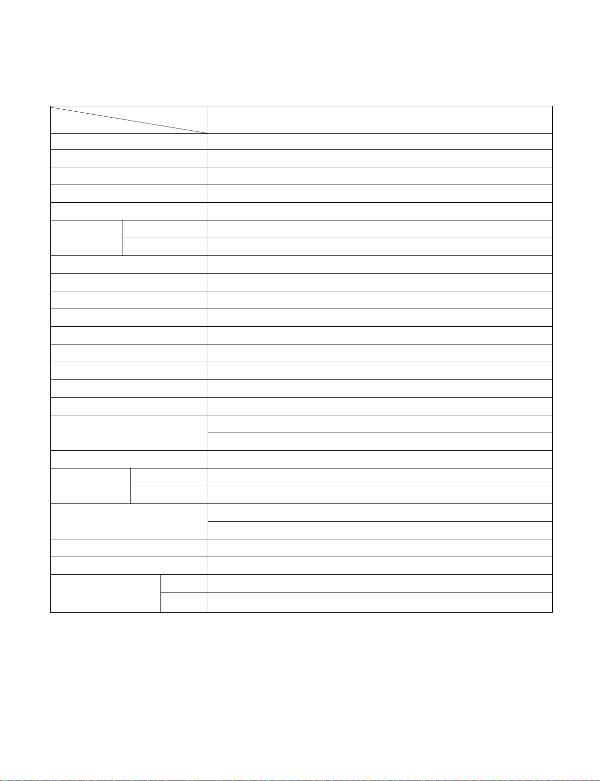
1.3 SPECIFICATIONS
POWER SUPPLY
COOLING CAPACITY (Btu/h)
INPUT (W)
RUNNING CURRENT (A)
E.E.R (Btu/W.h)
INDOOR (°C)
OUTDOOR (°C)
REFRIGERANT (R-22) CHARGE
EVAPORATOR
CONDENSER
FAN, INDOOR
FAN, OUTDOOR
FAN SPEEDS, FAN/COOLING
FAN MOTOR
OPERATION CONTROL
ROOM TEMP. CONTROL
AIR DIRECTION CONTROL
CONSTRUCTION
PROTECTOR
COMPRESSOR
FAN MOTOR
POWER CORD
DRAIN SYSTEM
NET WEIGHT
(lbs/kg)
OUTSIDE DIMENSION inch
(W x H x D) mm
10,000
1,020
9.2
9.8
26.7(DB)*
19.4(WB)**
35(DB)
23.9(WB)
439g (15.5 oz)
3 ROW 14 STACKS, S-FIN TYPE
2 ROW 16 STACKS, L-BENDED TYPE
TURBO FAN
PROPELLER TYPE FAN WITH SLINGER-RING
2/3
6 POLES
ROTARY SWITCH
THERMOSTAT
VERTICAL LOUVER (RIGHT & LEFT)
HORIZONTAL LOUVER (UP & DOWN)
SLIDE IN-OUT CHASSIS
OVERLOAD PROTECTOR
INTERNAL THERMAL PROTECTOR
1.8m(7') (3 WIRE WITH GROUDING)
ATTACHMENT PLUG (CORD-CONNECTED TYPE)
DRAIN PIPE OR SPLASHED BY FAN SLINGER
70/32
181/2x 137/8 x 2011/16
470 x 353 x 525
1ø, 115V, 60Hz
ZQ10A10B
MODELS
ITEMS
OPERATING
TEMPERATURE
* DB : dry bulb
** WB : wet bulb
Page 4
1.4 FEATURES
• Designed for cooling only.
• Powerful and whisper cooling.
• Slide-in and slide-out chassis for the simple
installation and service.
• Side air-intake, side cooled-air discharge.
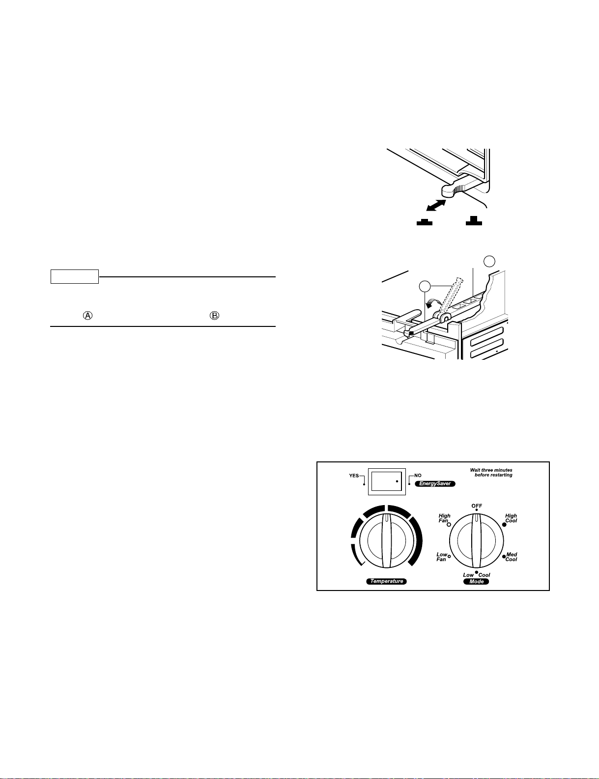
1.5 CONTROL LOCATIONS
1.5.1 CONTROL ONLY MODEL
• VENTILATION
The ventilation lever must be in the CLOSE position
in order to maintain the best cooling conditions.
When fresh air is necessary in the room, set the
ventilation lever to the OPEN position.
The damper is opened and room air is exhausted.
Before using the ventilation feature,
make a ventilation kit. First, pull down
part to horziontal line with part .
• FOR NORMAL COOLING
1. Turn the Mode switch to the High, Med or
Low Cool setting.
2. Set the Temperature control to the desired
temperature point (the mid-point is a good
starting position). If the room temperature is not
satisfactory after a reasonable time, adjust the
control to a cooler or warmer setting, as
appropriate.
• FOR MAXIMUM COOLING
1. Turn the Mode switch to the High Cool setting.
2. Set the temperature control to the highest
temperature point (all the way to the right).
• FOR QUIETER OPERATION
1. Turn the Mode switch to the Low Cool setting.
2. Set the Temperature control as needed.
• Energy Saver Switch
This rocker switch can be depressed to either YES
or NO. In the YES position, you will get the most
economical operation. Both the fan and the
compressor will cycle on and off together,
maintaining the selected temperature at a more
constant level and reducing the humidity more
efficiently. This control will only operate when the
unit is in a cooling mode. In the NO position, the
fan will run constantly as long as the unit is in the
cooling mode.
• Built in adjustable THERMOSTAT.
• Washable one-touch filter.
• Compact size.
• Reliable and efficient rotary compressor equipped.
—4—
CLOSE VENT OPEN
Part
A
Part
B
NOTE
Page 5
—5—
2.1 MECHANICAL PARTS
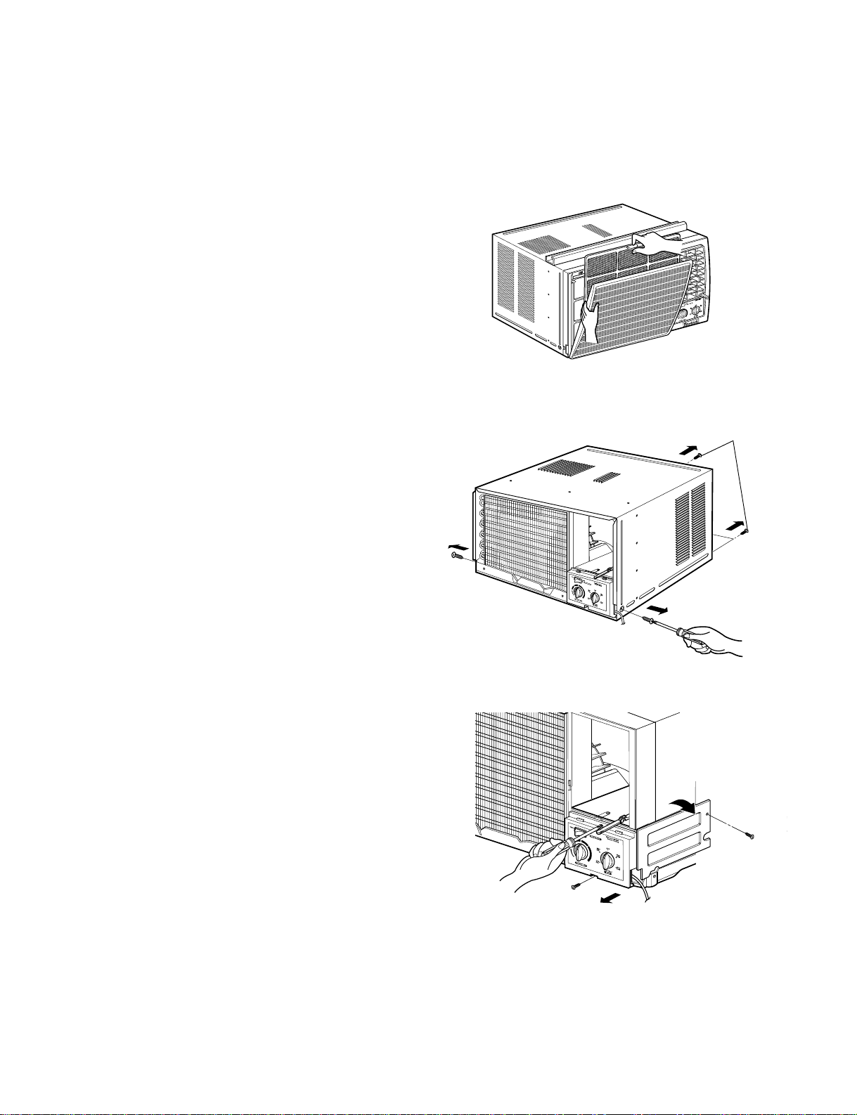
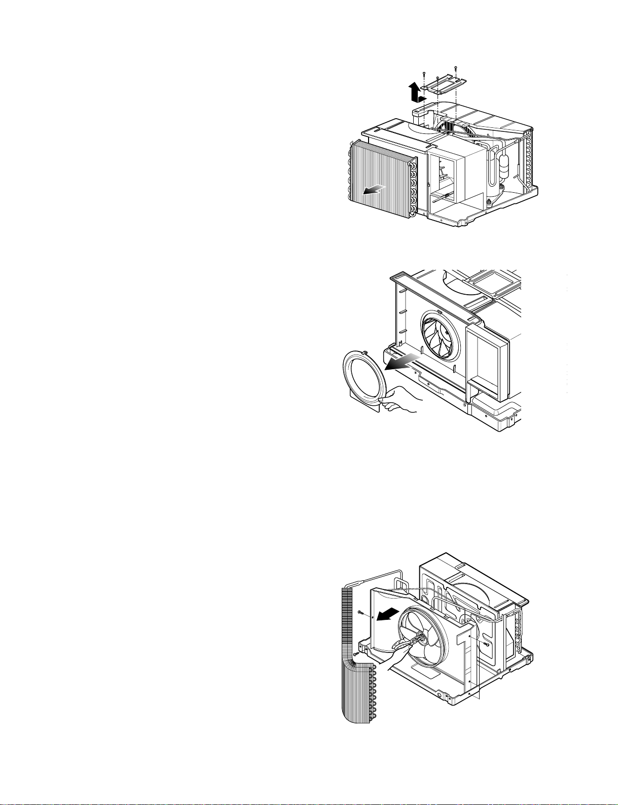
2.1.1 FRONT GRILLE
1. Open the INLET GRILLE downward and remove
the air filter.
2. Remove the screw which fastens the FRONT GRILLE.
3. Pull the FRONT GRILLE from the right side.
4. Remove the FRONT GRILLE.
5. Re-install the component by referring to the above
removal procedure. (See figure 1)
2.1.2 CABINET
1. After disassembling the FRONT GRILLE, remove
two screws which fasten the CABINET at both
sides.
2. Remove two screws which fasten the CABINET at
back.
3. Pull the BASE PAN forward. (See figure 2)
2.1.3 CONTROL BOX
1. Disconnect the unit from the power source.
2. Remove the front grille. (Refer to section 2.1.1)
3. Remove the cabinet. (Refer to section 2.1.2)
4. Remove the screw which fastens the control box
cover.
5. Remove the housing which connects motor wire in
the control box.
6. Remove the 3 leads from the compressor.
(Refer to section 2.3.1)
7.Discharge the capacitor by placing a 20,000
ohmresistor across the capacitor terminals.
8. Remove the 2 screws which fasten the control
box.(See Figure 3)
9. Pull the control box forward completely.
10. Re-install the components by referring to the
removal procedure, above. (See Figure 3)
(Refer to the circuit diagram found on page 24 in
this manual or on the control box.)
2. DISASSEMBLY INSTRUCTIONS
— Before disassembling, turn the POWER SWITCH to OFF and disconnect the power cord.
Shipping screws
Figure 1
Figure 2
Figure 3
Page 6
—6—
2.2 AIR HANDLING PARTS
2.2.1 AIR GUIDE AND BLOWER
1. Remove the front grille. (Refer to section 2.1.1)
2. Remove the cabinet. (Refer to section 2.1.2)
3. Remove the control box. (Refer to section 2.1.3)
4. Remove the 3 screws which fasten the brace.
5. Remove the brace.
6. Remove the 2 screws which fasten the evaporator.
7. Move the evaporator forward and pulling it upward
slightly. (See Figure 4)
8. Move the evaporator to the left carefully.
9. Pull out the hook of orifice by pushing the tabs and
remove it. (See Figure 5)
10. Remove the clamp with a hand plier which
secures the blower.
11. Remove the blower.
12. Remove the 4 screws which fasten the air guide
from the barrier.
13. Move the air guide backward, pulling out from the
base pan.
14. Re-install the components by referring to the
removal procedure, above.
2.2.2 FAN AND SHROUD
1. Remove the cabinet. (Refer to section 2.1.2)
2. Remove the brace (Refer to section 2.2.1)
3. Remove the screw which fastens the cover cond.
4. Remove the 5 screws which fasten the condenser.
5. Move the condenser to the left carefully.
6. Remove the clamp with a hand plier which secures
the fan.
7. Remove the fan and then pull out the shroud.
(See Figure 6)
8. Re-install the components by referring to the
removal procedure.
Figure 4
Figure 5
Figure 6
Page 7
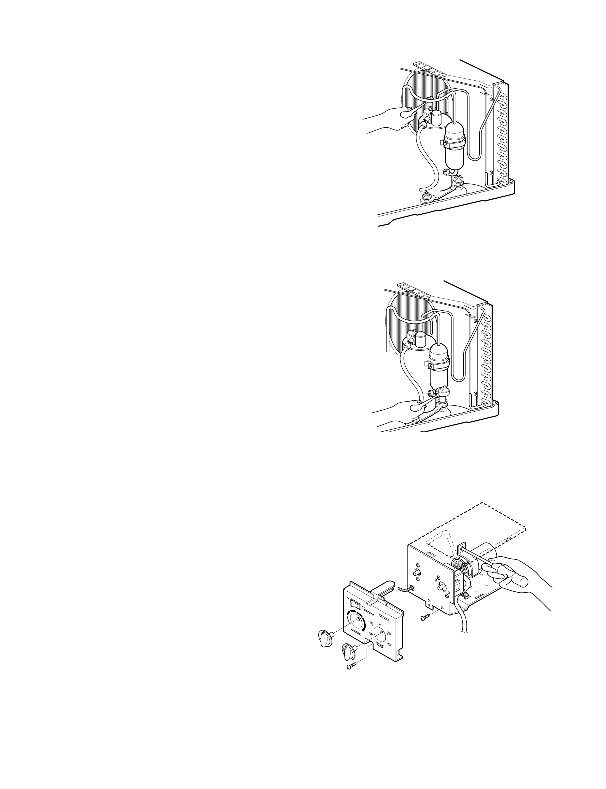
2.3 ELECTRICAL PARTS
2.3.1 OVERLOAD PROTECTOR
1. Remove the cabinet. (Refer to section 2.1.2)
2. Remove the nut which fastens the terminal cover.
3. Remove the terminal cover. (See Figure 7)
4. Remove all the leads from the overload protector.
5. Remove the overload protector.
6. Re-install the component by referring to the
removal procedure, above.
2.3.2 COMPRESSOR
1. Remove the cabinet. (Refer to section 2.1.2)
2. Discharge the refrigerant system using a Freon
TM
Recovery System.
If there is no valve to attach the recovery system,
install one (such as a WATCO A-1) before venting
the FreonTM. Leave the valve in place after
servicing the system.
3. Remove the overload protector. (Refer to section
2.3.1)
4. After purging the unit completely, unbraze the
suction and discharge tubes at the compressor
connections.
5. Remove the 3 nuts and the 3 washers which
fasten the compressor.
6. Remove the compressor. (See Figure 8)
7. Re-install the components by referring to the
removal procedure, above.
2.3.3 CAPACITOR
1. Remove the control box. (Refer to section 2.1.3)
2. Remove the knobs and the screw which fasten
control panel from control box.
3. Remove the screw which is located in the front.
4. Open the bottom side of control box.
5. Remove the screw and the clamp which fasten the
capacitor.
6. Disconnect all the leads of capacitor terminals.
7. Re-install the components by referring to the
removal procedure, above. (See Figure 9)
—7—
Figure 7
Figure 8
Figure 9
Page 8
—8—
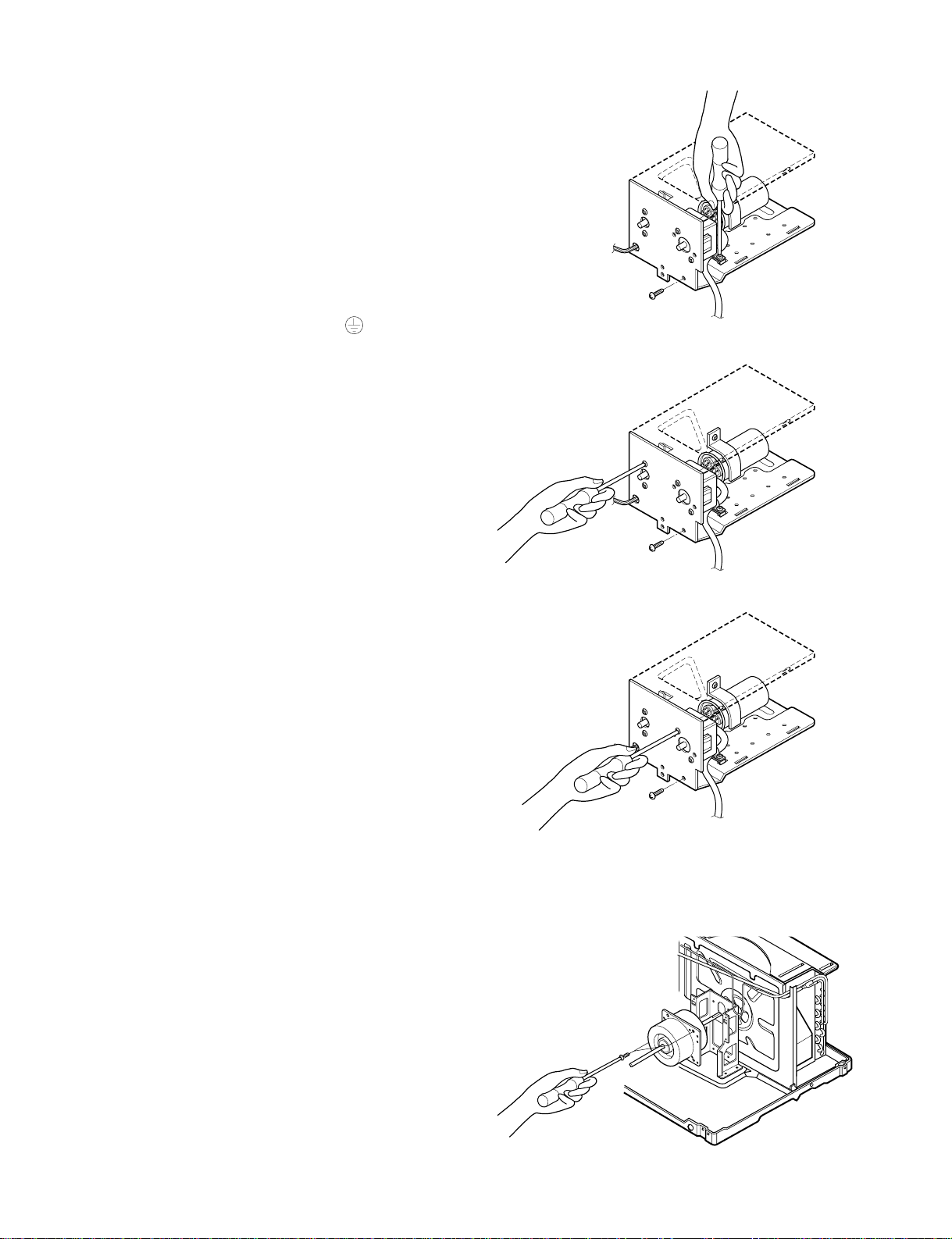
2.3.4 POWER CORD
1. Remove the control box. (Refer to section 2.1.3)
2. Open the control box. (Refer to section 2.3.3)
3. Disconnect the grounding screw from the control
box.
4. Disconnect the 2 receptacles.
5. Remove a screw which fastens the clip cord.
(See Figure 10)
6. Remove the power cord.
7. Re-install the component by referring to the above
removal procedure, above.
(Use only one ground-marked hole for ground
connection.)
8. If the supply cord of this appliance is damaged, it
must be replaced by the special cord. (The
special cord means the cord which has the same
specification marked on the supply cord attached
at the unit.)
2.3.5 THERMOSTAT
1. Remove the control box. (Refer to section 2.1.3)
2. Open the control box. (Refer to section 2.3.3)
3. Remove the 2 screws which fasten the thermostat.
4. Disconnect 2 leads of thermostat terminals.
5. Remove the thermostat.
6. Re-install the components by refereing to the
above removal procedure. (See Figure 11)
2.3.6 ROTARY SWITCH
1. Remove the control box. (Refer to section 2.1.3)
2. Open the control box. (Refer to section 2.3.3)
3. Remove the 2 screws which fasten the rotary
switch.
4. Disconnect all the leads of the rotary switch
terminals.
5. Remove the rotary switch.
6. Re-install the components by referring to the
above removal procedure. (See Figure 12)
2.3.7 MOTOR
1. Remove the cabinet. (Refer to section 2.1.2)
2. Remove the evaporator. (Refer to section 2.2.1)
3. Remove the orifice. (Refer to section 2.2.1)
4. Remove the blower. (Refer to section 2.2.1)
5. Remove the fan. (Refer to section 2.2.2)
6. Remove the control box cover and housing of the
motor in the control box. (Refer to section 2.1.3)
7. Remove the 2 screws which fasten the motor from
the mount motor. (See Figure 13)
8. Remove the motor.
9. Re-install the components by referring to the
removal procedure, above.(See Figure 13)
Figure 10
Figure 11
Figure 12
Figure 13
Page 9
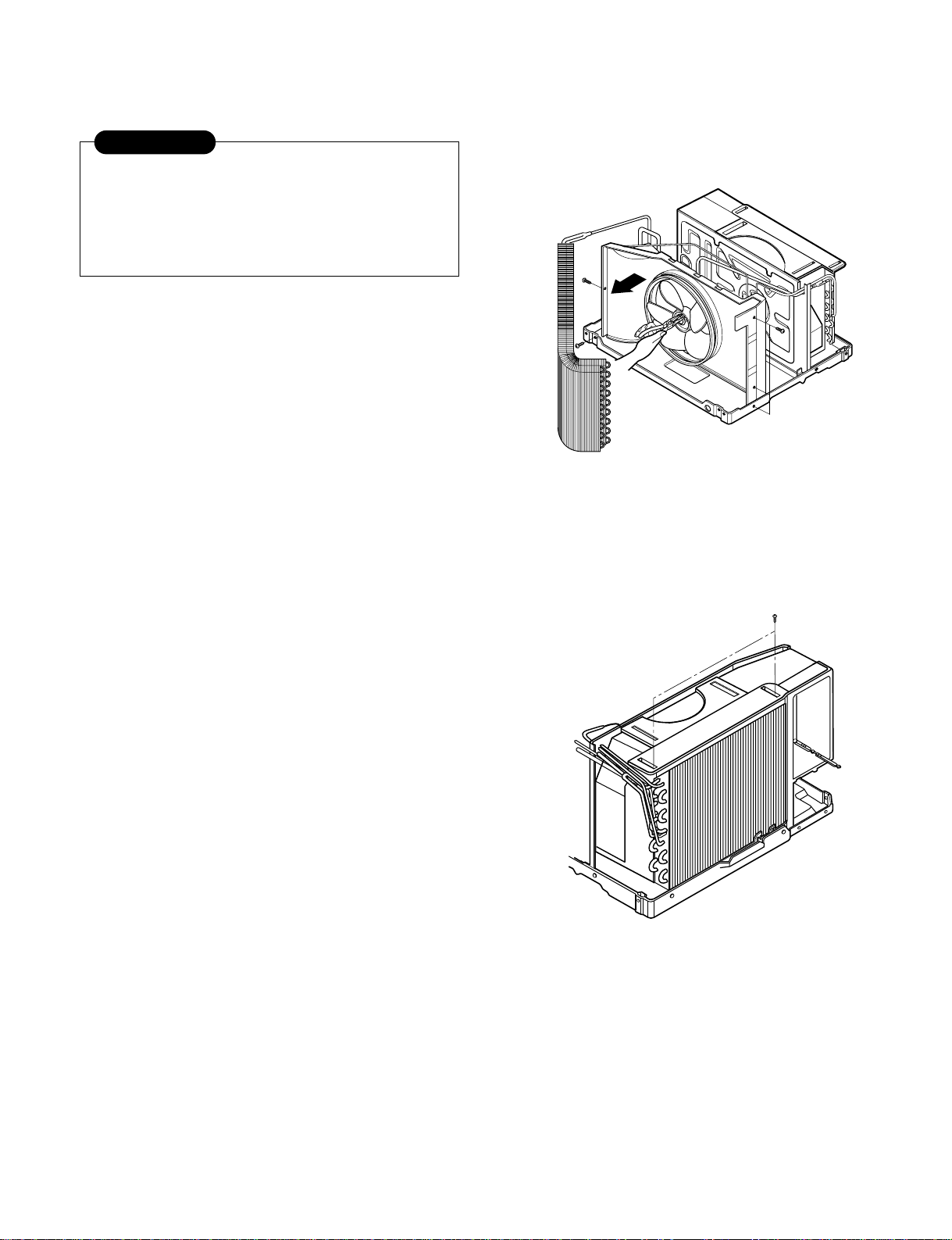
2.4 REFRIGERATING CYCLE
2.4.1 CONDENSER
1. Remove the cabinet. (Refer to section 2.1.2)
2. Remove the 3 screws which fasten the
brace.(Refer to section 2.2.1)
3. Remove the screw which fastens the cover cond.
4. Remove the 5 screws which fasten the condenser
and shroud.
5. After discharging the refrigerant completely,
unbraze the interconnecting tube at the condenser
connections.
6. Remove the condenser carefully.
7. Re-install the components by referring to the
removal procedure.
(See Figure 14)
2.4.2 EVAPORATOR
1. Remove the cabinet. (Refer to section 2.1.2)
2. Remove the 2 screws which fasten the evaporator.
3. Move the evaporator sideways carefully.
(Refer to section 2.2.1)
4. After discharging the refrigerant completely,
unbraze the interconnecting tube at the evaporator
connections.
5. Remove the evaporator carefully.
6. Re-install the component by referring to notes.
(See Figure 15)
2.4.3 CAPILLARY TUBE
1. Remove the cabinet. (Refer to section 2.1.2)
2. After discharging the refrigerant completely,
unbraze the interconnecting tube at the capillary
tube.(See caution above)
3. Remove the capillary tube.
4. Re-install the component by referring to notes.
—9—
Figure 14
Figure 15
Discharge the refrigerant system using a
FreonTMRecovery System.
If there is no valve to attach the recovery
system, install one (such as a WATCO A-1)
before venting the FreonTM. Leave the valve in
place after servicing the system.
CAUTION
Page 10

—10—
— Replacement of the refrigeration cycle.
1. When replacing the refrigeration cycle, be sure to
Discharge the refrigerant system using a Freon
TM
recovery System.
If there is no valve to attach the recovery system,
install one (such as a WATCO A-1) before venting
the FreonTM. Leave the valve in place after
servicing the system.
2. After discharging the unit completely, remove the
desired component, and unbraze the pinch-off
tubes.
3. Solder service valves into the pinch-off tube ports,
leaving the valves open.
4. Solder the pinch-off tubes with Service valves.
5. Evacuate as follows.
1) Connect the vacuum pump, as illustrated figure
16A.
2) Start the vacuum pump, slowly open manifold
valves A and B with two full turns
counterclockwise and leave the valves open.
The vacuum pump is now pulling through valves
A and B up to valve C by means of the manifold
and entire system.
3) Operate the vacuum pump for 20 to 30 minutes,
until 600 microns of vaccum is obtained. Close
valves A and B, and observe vacuum gauge for
a few minutes. A rise in pressure would
indicate a possible leak or moisture remaining in
the system. With valves A and B closed, stop
the vacuum pump.
4) Remove the hose from the vacuum pump and
place it on the charging cylinder. See figure
16B.
Open valve C.
Discharge the line at the manifold connection.
5) The system is now ready for final charging.
6. Recharge as follows :
1) Refrigeration cycle systems are charged from
the High-side. If the total charge cannot be put
in the High-side, the balance will be put in the
suction line through the access valve which you
installed as the system was opened.
2) Connect the charging cylinder as shown in figure
16B.
With valve C open, discharge the hose at the
manifold connection.
3) Open valve A and allow the proper charge to
enter the system. Valve B is still closed.
4) If more charge is required, the high-side will not
take it. Close valve A.
5) With the unit running, open valve B and add the
balance of the charge.
a. Do not add the liquid refrigerant to the Low-
side.
b. Watch the Low-side gauge; allow pressure to
rise to 30 lbs.
c. Turn off valve B and allow pressure to drop.
d. Repeat steps b. and c. until the balance of the
charge is in the system.
6) When satisfied the unit is operating correctly,
use the pinch-off tool with the unit still running
and clamp on to the pinch-off tube. Using a tube
cutter, cut the pinch-off tube about 2 inches from
the pinch-off tool. Use sil-fos solder and solder
pinch-off tube closed. Turn off the unit, allow it to
set for a while, and then test the leakage of the
pinch-off connection.
NOTES
If high vacuum equipment is used, just crack
valves A and B for a few minutes, then open
slowly with the two full turns counterclockwise.
This will keep oil from foaming and being
drawn into the vacuum pump.
CAUTION
Page 11

—11—
Equipment needed: Vacuum pump, Charging cylinder, Manifold gauge, Brazing equipment. Pin-off tool capable
of making a vapor-proof seal, Leak detector, Tubing cutter, Hand Tools to remove components, Service valve.
A
COMPOUND GAUGE
EVAPORATOR
(LOW PRESSURE SIDE)
COMPRESSOR
CAPILLARY TUBE
CONDENSER
(HIGH PRESSURE SIDE)
SEE INSETS
BELOW
MANIFOLD
GAUGE
B
Figure 16A-Pulling Vacuum
Figure 16B-Charging
A
B
EXTERNAL
VACUUM PUMP
A
CHARGING
CYLINDER
LOW
HI
B
C
Page 12

—12—
3. INSTALLATION
3.1 INSTALLATION HARDWARE
Type C (5)
Type A (13)
Bolt (2)
Nut (2)
Type B (3)
Foam top
window gasket
Window sash seal
Window locking
bracket
Left frame curtain
Frame guide(2)
Sill support(2)
Right frame
curtain
3.2 SELECT THE BEST LOCATION
Step 1. To prevent vibration and noise, make sure the unit is
installed securely and firmly
Step 2. If possible, install the unit where sunlight does not shine
directly on the unit.
Step 3. The outside of the cabinet must extend
outward for at least 11" and there should be no
obstacles, such as a fence or wall, within 20" from the
back of the cabinet because it will prevent heat
radiation of the condenser.
Restriction of outside air will greatly reduce the cooling
efficiency of the air conditioner.
Step 4. Install the unit with a little tilt outward not to leak the
condensed water into the room (about 10~15cm or 1/4
bubble with level).
CAUTION: All side louvers of the cabinet must remain exposed
to the outside of the structure.
Over 20"
About 1/2"
HEAT
RADIATION
FENCE
AWNING
COOLED
AIR
30"~60"
Level
1/4 Bubble
Page 13

—13—
3.3 WINDOW REQUIREMENTS
Step 1. These instructions are for a standard double hung
window. You will need to modify them for other
types of windows.
Step 2. The air conditioner can be installed without the
frame curtain if needed to fit in a narrow window.
See the window opening dimensions to the right.
Step 3. All supporting parts must be secured to firm wood,
masonry, or metal.
Step 4. The electric outlet must be within reach of the power
cord.
3.4 STORM WINDOW REQUIREMENTS
A storm window frame will not allow the air conditioner to tilt
toward the outside and will keep it from draining properly.
To adjust for this, attach a piece of wood to the stool.
WOOD PIECES–
Width: Minimum 1 1/2"(38mm)
Length: Long enough to fit inside the window frame.
Thickness: To determine the thickness, place a piece of
wood on the stool to make it 1/2" higher than the top of the
storm window frame.
Attach securely with nails or screws provided.
25" to 36"
Stool
Offset
1
/2" to 11/4"
Sill
Exterior
Interior wall
(Without frame curtain)
(With accordion panels)
Storm window
frame
Wood
Stool
1
/2" higher
than frame
18 1/2" min
15" min
(With frame curtain)
Page 14

✓ Remove the 2 shipping screws from the back of the
case.
✓ Remove the 2 screws on each side of the case.
Keep these for later use.
✓ Slide the air conditioner from the case by gripping
the base pan handle and pulling forward while
bracing the case.
3.6 BEFORE INSTALLATION...
✓ Cut the window sash seal to the proper length. Peel
off the backing and attach the seal to the underside
of the window sash.
✓ Carefully insert the plastic frame guides into the
bottom of the case on each side.
When the frame guides are set, the arrows should be
pointing toward the back end of the unit.
✓ Insert the frames for the frame curtains into the top
mounting rail and the frame guides. Attach the
frame curtains to the side of the case using 4 type A
screws
—14—
Shipping screws
Window sash seal
Frame
guide
Bottom of
case
(Type A)
(Type A)
3.5 PREPARING THE UNIT FOR INSTALLATION
Page 15

Step 1. Open the window and mark the centerline of
the window stool (or desired air conditioner
location).
Step 2. Carefully place the case on the window stool
and align the center mark on the bottom front
with the centerline of the stool
Step 3. Pull the window down behind the top
mounting rail
NOTE: Do not shut the window so tightly that
movement of the frame curtains is restricted.
Step 4. Loosely assemble the sill supports.
Step 5. Select the position that will place the sill
supports near the outermost point on the sill.
Attach the sill supports to the case track hole
in relation to the selected position using 2 type
A screws in each support.
Step 6. Adjust the bolt and the nut in each support so
that the case is installed with a slight
downward tilt (about 1/2").
Step 7. Secure the case to the window stool by using
3 type B screws.
Step 8. Pull the frame curtains to each window sash
track. Attach them on each side to the window
sash and the window stool using 4 type C
screws.
Step 1. Attach the window locking bracket with type C
screw.
Step 2. Cut the foam top window gasket to the
window width.
Step 3. Stuff the foam between the glass and the
window to prevent air and insects from getting
into the room.
—15—
3.7 INSTALL THE CASE IN THE WINDOW
3.8 INSTALL THE WINDOW LOCKING BRACKET
AND THE FOAM TOP WINDOW GASKET
Top
mounting
rail
Front angle
Window stool
Sash
seal
Cabinet
Frame curtains
INDOOR
OUTDOOR
Sill Support
Nut
Bolt
INDOOR
OUTDOOR
ABOUT 1/2"
Cabinet
Screw(Type A)
Frame guide
(Type C)
Screw
Sash
Track
Front Angle
Screw(Type B)
Sill Support
(Type C)
Screw
Foam top window gasket
Top
mountaing rail
Window Sash
Page 16

Step 1. Slide the air conditioner into the case. Reinstall the
2 screws removed earlier on each side of the case.
Step 2. Before installing the front grille, pull out
the vent control lever located above the unit control
knobs, as shown.
Step 3. Attach the front grille to the case by inserting the
tabs on the grille into the slots on the front of the
case. Push the grille in until it snaps into place.
When you detach the front grille from the case, push the
grille to your right side and pull it toward you.
Step 4. Lift the inlet grille and secure the front grille with a
type A screw. Lower the inlet grille into place.
The Friedrich ZQ08A10A has a reversible grille. The grille is
designed to open from both the top and the bottom.
To reverse the grille opening, you must follow the following
steps;
Step 1. Pull the entire grill of the front of the unit and locate
the hinges that hold the grille in place on the inside
of the grille.
Step 2. Insert the tip of a flat screwdriver in between one of
the Hinges and the ball shaped bearing of the grille.
Step 3. Very carefully pull the bearing out of the socket of
the Hinge and repeat steps 1-3 for the remaining
hinge and socket.
Step 4. Locate the top hinges on the grille.
Step 5. Turn the grille upside down and using flat
screwdriver, create an opening on the top hinge and
insert the ball shaped bearing to snap the grille in
place. Repeat the same steps on the remaining
hinge.
—16—
Inlet Grille
Power Cord
Screw
Screw
3.9 INSTALL THE AIR CONDITIONER IN THE CASE
3.10 TO REVERSE THE GRILLE OPENING
Page 17

—17—
4. TROUBLESHOOTING GUIDE
4.1 OUTSIDE DIMENSIONS
525mm(20 11/16")
470mm(18 1/2")
353mm(13
7
/8")
250mm(10")
Page 18

—18—
CAPILLARY TUBE
COMPRESSOR
BLOWER
EVAPORATOR COIL
: REFRIGERANT FLOW
CONDENSER COIL
FAN
MOTOR
4.2 PIPING SYSTEM
The following is a brief description of the important components and their function in what is called the refrigeration
system. Reference should made to figure 17 to follow the refrigerating cycle and the flow of the refrigerant in the
cooling cycle.
MOTOR
COMPRESSOR
OIL
(LIQUID REFRIGERANT)
CAPILLARY TUBE
OUTSIDE COOLING
AIR FOR REFRIGERANT
PASS THROUGH
SUCTION LINE
COOL LOW PRESSURE VAPOR
COOLED
AIR
COMPLETE LIQUID
BOIL OFF POINT
LIQUID
PRESSURE
DROP
ROOM AIR HEAT LOAD
VAPOR INLET
HOT
DISCHARGED
AIR
LIQUID OUTLET
HIGH PRESSURE VAPOR
LIQUID REFRIGERANT
LOW PRESSURE VAPOR
ROOM AIR CONITIONER
EVAPORATOR COILS CONDENSER COILS
CYCLE OF REFRIGERATION
Discharge the refrigerant system using a FreonTMRecovery
System. If there is no valve to attach the recovery system,
install one (such as a WATCO A-1) before venting the FreonTM.
Leave the valve in place after servicing the system. Do not
vent FreonTMinto the atmosphere.
Figure 17
Page 19

—19—
4.3 TROUBLESHOOTING GUIDE
In general, possible trouble is classified in two kinds.
The one is called Starting Failure which is caused from an electrical defect. The other is Ineffective Air
Conditioning caused by a defect in the refrigeration circuit and improper application.
Unit runs but poor cooling is ineffective.
Ineffective Cooling
Check of outdoor coil
(heat exchanger) & fan
operation.
Check gas leakage.
Repair gas leak.
Replacement of unit if the
unit is beyond repair.
Satisfactory operation with
temperature difference of
inlet & outlet air ;
44~50°F(7~10°C)
Check heat load
increase.
Clean condenser.
Not on separate circuit
Check inside gas
pressure.
Adjusting of refrigerant
charge
Malfunction of compressor
Replacement of
compressor
Check of cold air circulation
for smooth flow.
Dirty indoor coil
(Heat exchanger)
Remove obstruction.
Check clogging in
refrigeration circuit.
Repair clogging in
refrigeration circuit.
Obstruction at air outlet
Clogged of air filter
Malfunction of fan
Page 20

—20—
Fails to Start
Check of circuit breaker
and fuse.
Gas leakage of feeler bulb
of thermostat
Check of control switch.
Only fan fails to start.
Improper wiring
Defect of fan motor
capacitor
Resistance irregular motor
( ).
Insulation irregular motor
( ).
Replacement of fan motor
Regular but fails to start
Replacement of compressor
(Locking of rotor, metal)
Improper thermostat setting
Loose terminal connection
Improper wiring
Irregular motor resistance ( )
Irregular motor insulation ( )
Replacement of compressor
(Motor damaged)
Drop of power voltage
Check capacitor.
Replacement
Only compressor fails to
start.
Defect of compressor
capacitor
Check of power source.
Check of control switch
setting.
Page 21

—21——21—
COMPLAINT CAUSE REMEDY
Check voltage at outlet. Correct if none.
Check voltage to rotary switch. If none, check
power supply cord. Replace cord if circuit is open.
Check switch continuity. Refer to wiring diagram
for terminal identification. Replace switch if none
defective.
Connect wire. Refer to wiring diagram for terminal
identification. Repair or replace loose terminal.
Test capacitor.
Replace if not within ±10% of manufacturer's
rating. Replace if shorted, open, or damaged.
Fan blade hitting shroud or blower wheel hitting
scroll. Realign assembly.
Units using slinger ring condenser fans must
have 2/9to 1/4inch clearance to the base. If it is
the base, shim up the bottom of the fan
motor with mounting screw(s).
Check fan motor bearings; if motor shaft will not
rotate, replace the motor.
Check voltage. See limits on this page. If not within
limits, call an electrician.
Test capacitor.
Check bearings. Does the fan blade rotate freely?
If not, replace fan motor.
Pay attention to any change from high speed to
low speed. If the speed does not change, replace
the motor.
No power
Power supply cord
Rotary switch
Wire disconnected or
connection loose
Capacitor (Discharge
capacitor before testing.)
Will not rotate
Revolves on overload.
Fan motor will not run.
Fan motor runs
intermittently.
ROOM AIR CONDITIONER VOLTAGE LIMITS
NAME PLATE RATING MINIMUM MAXIMUM
115V 103.5V 126.5V
Page 22

—22—
COMPLAINT CAUSE REMEDY
If cracked, out of balance, or partially missing,
replace it.
If cracked, out of balance, or partially missing,
replace it.
Tighten it.
If knocking sounds continue when running or loose,
replace the motor. If the motor hums or noise
appears to be internal while running, replace motor.
Check voltage. See the limits on the preceding page.
If not within limits, call an electrician.
Check the wire connections ; if loose, repair or
replace the terminal. If the wires are disconnected,
refer to wiring diagram for identification, and replace
the wires. Check the wire connections ; if not
according to the wiring diagram, correct the
connections.
Check for continuity, refer to the wiring diagram for
terminal identification. Replace the switch if the
circuit is open.
Check the position of knob. If not at the coldest
setting, advance the knob to this setting and restart
the unit.
Check the continuity of the thermostat. Replace the
thermostat if the circuit is open.
Check the capacitor.
Replace if not within ±10% of manufacturer's rating,
replace if shorted, open, or damaged.
Check the compressor for open circuit or graond. If
open or grounded, replace the compressor.
Check the compressor overload if externally
mounted.
Replace if open. (If the compressor temperature is
high, remove the overload, cool and retest.)
Check the voltage. See the limits on the preceding
page. If voltage is not within these limits, call an
electrician.
Check overload, if externally mounted.
Replace if open. (If the compressor temperature is
high, remove the overload, cool, and retest.)
Fan
Blower
Loose set screw
Worn bearings
Voltage
Wiring
Rotary
Thermostat
Capacitor (Discharge
capacitor before
servicing.)
Compressor
Overload
Voltage
Overload
Fan motor noise.
Compressor will not run,
fan motor runs.
Compressor cycles on
overload.
Page 23

—23—
COMPLAINT CAUSE REMEDY
If not running, determine the cause. Replace if
required.
Remove the cabinet, inspect the interior surface of
the condenser. If restricted, clean carefully with a
vacuum cleaner (do not damage fins) or brush.
Clean the interior base before re-assembling.
If the condenser fins are closed over a large area on
the coil surface, head pressures will increase,
causing the compressor to cycle.
Straighten the fins or replace the coil.
Test the capacitor.
Check the terminals. If loose, repair or replace.
Check the system for a restriction.
If restricted, clean or replace.
Close if open.
Determine if the unit is properly sized for the area to
be cooled.
Check the set screw, or clamp. If loose or missing,
correct. If the blower or fan is hitting scroll or barrier,
rearrange the air handling parts.
Remove the cabinet and carefully rearrange the
tubing not to contact the cabinet, compressor,
shroud and barrier.
Fan motor
Condenser air flow
restriction
Condenser fins
(damaged)
Capacitor
Wiring
Refrigeration system
Air filter
Exhaust damper door
Unit undersized
Blower or fan
Copper tubing
Compressor cycles on
overload
Insufficient cooling
Excessive noise
Page 24

—24—
5. SCHEMATIC DIAGRAM
• CIRCUIT DIAGRAM
• MODEL : ZQ10A10B
WH(BL)
POWER INPUT
BK(BR)
(Ribbed) (Plain)
GN/YL
(GN)
GN/YL(GN)
THERMISTOR
BK BK
BLRDBL
RD
CN-TH1
YL YL
OR(BR) OR(BR)
OR(BR)
SYNC
MOTOR
RY-LO
RY-HI
CN-WORK
CN-SYNC CN-DISP
DISPLAY P.W.B ASM
RY-SYNC
250V/T2A
(115V/T2A)
TRANS
FORMER
ZNR
RY-COMP
MAIN P.W.B ASM
BK
BK
BR
BR
RD
BL BL
OLP
RD
MOTOR
CAPACITOR
F
R
S
COMP.
C
C
H
3854AR2330P
WIRING DIAGRAM
RY-MID
FUSE
RD
BK
PTC
43
LOCATION
NO.
1 POWER CORD ASS'Y 2H00677R 1
2 MOTOR ASS'Y 4681A20027J 1
3 COMPRESSOR 2520UKEC2CB 1
4 ROTARY SWITCH 2H00598E 1
5 THERMOSTAT 2H01109L 1
6 CAPACITOR, SH 0CZZA20001N 1
7 CONNECTOR ASS'Y 6631AR3843P 1
9 CONNECTOR ASS'Y 6631AR2687R 1
10 OVERLOAD PROTECTOR 6750U-L049A 1
DESCRIPTION
PART NO.
ZQ10A10A
REMARKS
Q'TY
PER SET
Page 25

—25—
6. EXPLODED VIEW
16
34
62
63
49 53
52
51
50
49
48
6
56
55
61
57
60
59
58
25
2928
31
26
22
23
17
18
19
27
20
29
30
3
2
10
9
7
1
21
24
37
3643
42
47 46
41
4044
151413
12
11
8
35
32
45
38
E
A
C
D
B
5
4
39
33
54
Page 26

—26—
7. REPLACEMENT PARTS LIST
• MODEL: ZQ10A10B
PART NO.
DESCRIPTION
REMARK
1
1
1
1
1
2
1
3
1
3
3
1
1
1
1
1
1
1
1
1
1
1
1
2
4
1
1
1
1
2
1
1
1
1
1
R
R
R
R
R
R
R
R
R
N
N
R
R
R
R
R
R
R
R
R
R
R
R
N
N
R
R
R
R
R
R
R
R
R
R
ZQ10A10B
LOCATION
NO
.
FRIEDRICH
PART
NO.
Q'TY
PER SET
673-060-02
673-044-02
673-061-01
673-043-02
673-062-01
673-062-50
673-037-03
673-018-00
673-017-00
673-011-00
673-010-00
673-068-00
673-035-02
673-069-01
673-069-00
673-025-00
673-039-01
673-071-00
FRONT GRILLE ASSY
FRONT GRILLE
INLET GRILLE
AIR FILTER ASSY
LOUVER, HORIZONTAL
VERTICAL LOUVER
CABINET ASSY
COMP & ACCESSORY ASSY
ANTI-VIBRATION BUSH
COMPRESSOR
BRACKET, WASHER
HEXAGON NUTS
GASKET
OVERLOAD PROTECTOR
TERMINAL COVER
GASKET-NUT
NUT, TERMINAL COVER
BASE PAN WELD ASSY
BARRIER, SINGLE
SCROLL
AIR GUIDE
VENTILATION DAMPER
MOTOR MOUNT
MOTOR ASSY
SCREW
SCREW, TAP
COVER, COND.
SHROUD
FAN, TURBO
FAN
CLAMP SPRING
ORIFICE
BRACE
EVAPORATOR ASSY
CONDENSER ASSY
RUBBER
3531A20034C
3530A10026A
3530A10028A
5231A20004A
4758A20002A
4758A30008A
3091A30005C
4830AR4335A
2520UKLC2CA
4810AR4155B
1NHA0801206
4986U-L001G
6750U-L031A
3550U-L006A
4H01058A
4H00947A
3041A30005P
4790A10008A
3072A20004A
5238A10006A
4901A30001A
4960A20014A
4681A20027J
4000W4A003A
4H00006D
3550A30064A
4998A10010A
5900A20016A
5900A20015A
3H02932B
4948A30007A
4800A30001A
5421A20061F
5403A20043B
4H02023A
A
1
2
3
4
5
6
B
7
8
9
10
11
12
13
14
15
16
17
18
19
20
21
22
23
24
25
26
27
28
29
30
31
32
33
34
Page 27

—27—
PART NO.
DESCRIPTION
REMARK
ZQ10A10B
LOCATION
NO
.
FRIEDRICH
PART
NO.
Q'TY
PER SET
C CONTROL BOX ASSY 4995A20118N 1 R
35 673-054-01 CONTROL BOX, SINGLE 4994A10006B 1 R
36 673-055-01 CONTROL PANEL ASSY 3721A20037B 1 R
37 673-041-03 KNOB ASSY 4941A30011A 2 R
38 CAPACITOR 0CZZ20001V 1 R
39 673-006-00 CAPACITOR CLAMP 4H00442N 1 R
40 POWER CORD ASSY 2H00677R 1 R
41 673-004-02 THERMOSTAT 2H01109L 1 R
42 673-005-01 ROTARY SWITCH 2H00598E 1 R
43 673-057-01 ROCKER SWITCH 2H01316C 1 R
44 CLIP CORD 4H01762A 1 R
45 673-003-62 LEAD WIRE ASSY 6631AR2687A 1 R
46 CONDUCT ASSY 6631AR3843P 1 R
47 COVER, CONTROL BOX 3550A30036B 1 R
D PIPE
48 SUCTION TUBE ASSY 5211A20130R 1 R
49 DISCHARGE TUBE 5211AR2930Z 1 R
50 TUBE EVAPORATOR 5210A21847A 1 R
51 TUBE EVAPORATOR 5210A20847B 1 R
52 TUBE ASSY, CONNECTOR 5211AR7059Y 1 R
53 CAPILLARY 5211A20598B 1 R
54 DRIER ASSY 5851A30001F 1 R
E 673-063-03 INSTALL PART ASSY 3127AR3403M 1 R
55 673-040-02 UPPER GUIDE 5210AR3196F 1 R
56 673-038-02 CURTAIN ASSY 4959AR3402A 1 R
57 673-038-03 CURTAIN ASSY 4959AR3402B 1 R
58 673-065-00 BRACKET, ANGLE 4810AR3240A 2 R
59 673-067-00 NUT, HEXAGON 1NHC1000006 2 R
60 673-066-00 BOLT 1BHD1004006 2 R
61 673-064-00 FRAME GUIDE 3210AR3337A 2 R
62 673-069-02 WASHER, PLAIN 4H01029D 1 R
63 673-070-00 DRAIN, PIPE 3H02773A 1 R
Page 28

ZQ10 (03/01)Printed in the U.S.A
Post Office Box 1540 • 4200 N. Pan Am Expressway • San Antonio, Texas 78295-1540
• (210) 357-4400 • FAX (210) 357-4480
FRIEDRICH AIR CONDITIONING CO.
Visit our web site at www.friedrich.com
P/NO.: 3828A20038V
Use Factory Certified Parts...
 Loading...