

Page 1
Installation and Operation Manual
Room Air Conditioners
AUTO
F
C
AUTO FAN
AM
CONTINUOUS
PM
ONOFF
SET POINT
SCHEDULE
ROOM TEMP
CHECK $MART
AUTO SPEED
FILTER
SYSTEM
FAN MODE
POWER
FAN SPEED
SCHEDULE
Q Chassis Models
93001003_01
115 - V o lt :
SQ05, SQ06, SQ08, SQ10
115-Volt: EQ08
Page 2
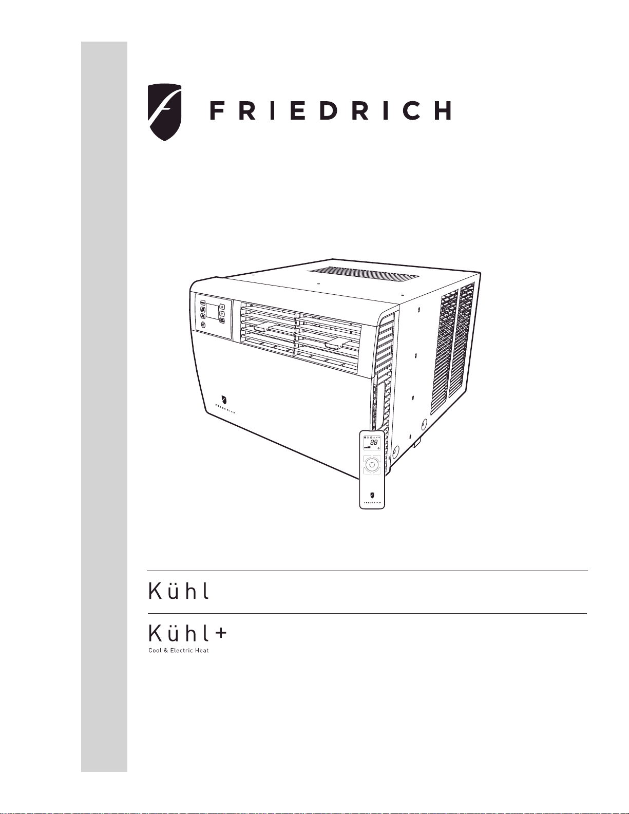
Thank you for your decision to purchase the Friedrich High Effi ciency Air Conditioner. Your new Friedrich has been carefully engineered and manufactured to
give you many years of dependabl e, effi cient operation, maintaining a co mfo rtable temperature and humidity level. Many extra features have been built into
your unit to assure quiet operation, the greatest circulation of cool, dry air, and the most economic operation.
THANK Y OU, on behalf of our entire company ,
for making such a wise purchase .
FRIEDRICH
AIR CONDITIONING CO.
SAN ANTONIO, TX
MODEL NUMBER
EQ08N11-A
SERIAL NUMBER
AALY00219
VOLTS
115
103 VOLT MIN.
COOLING:
BTU/HR
7500
EER
9.8
AMPS
6.9
HEATING:
BTU/HR
4000
EER
AMPS
11.2
MAX AMPS:
23.5 OZS.
DESIGN PRESSURES
600 PSIG HS
300 PSIG LS
U.S. PATENTS
D458, 229 S
5,634,346
IF CONNECTED TO
A FUSE PROTECTED
CIRCUIT, USE A 12 A
TIME DELAY FUSE
LISTED 183H
ROOM AIR
CONDITIONER
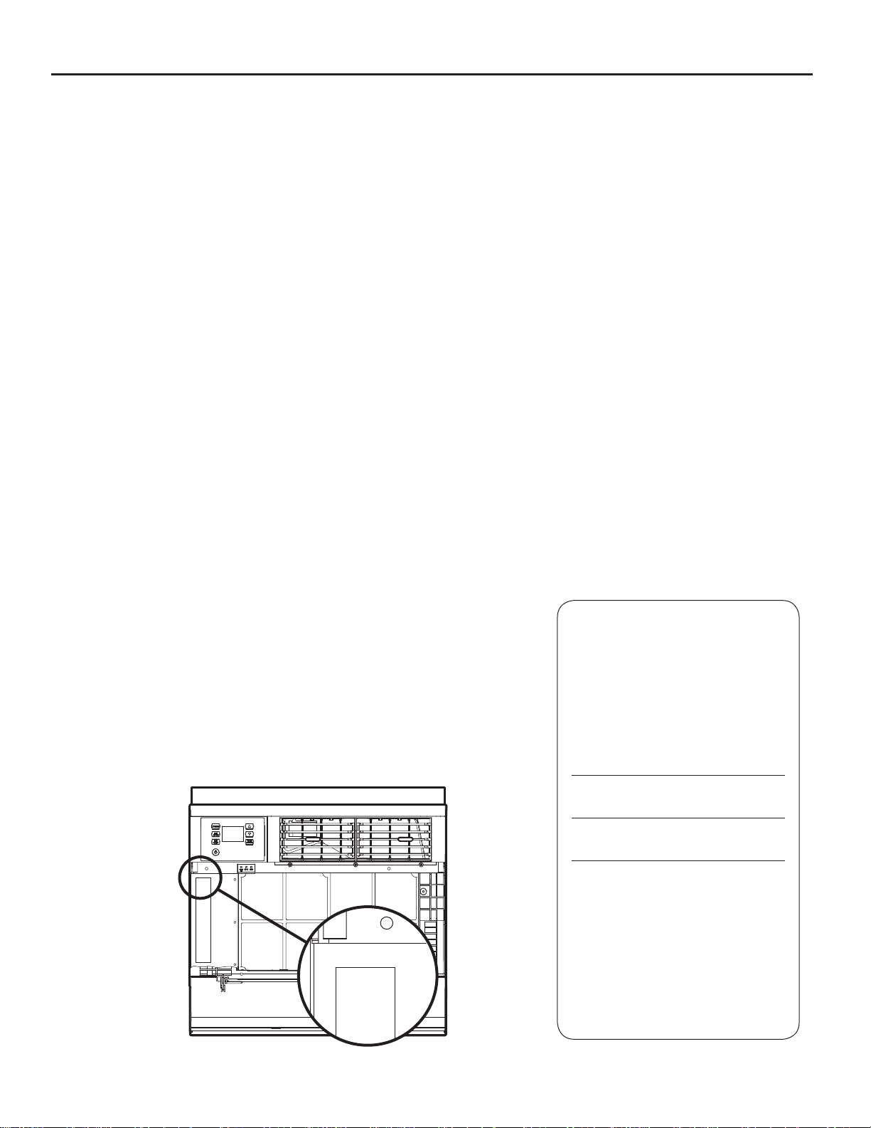
Register your air conditioner
Model information can be found on the name
plate behind the front cover.
Please complete and mail the owner
registration card furnished with this product,
or register online at www.friedrich.com. For
your future con ve nience, record the model
information here.
MODEL NUMBER
SERIAL NUMBER
PURCHASE DATE
60 HZ/ 1PH
FRIEDRICH
AIR CONDITIONING CO.
SAN ANTONIO, TX
Assembled in Mexico
MODEL NUMBER
EQ08N11-A
SERIAL NUMBER
AALY00219
VOLTS
60 HZ/ 1PH
2
Page 3

T able of Contents
Table of Contents ......................................................................................................................................................................................................................................................................................3
Safety Precautions ...................................................................................................................................................................................................................................................................................4
Unpacking Instructions ............................................................................................................................................................................................................................................................................5
WARNING: Before Operating Your Unit ..............................................................................................................................................................................................................................................6
Standard Filter Cleaning / Installation Instructions .......................................................................... ....................................................................................................................................................7
Premium Carbon Filter Installation Instructions ...................................................................................................................................................................................................................................7
Control Panel Operation ..........................................................................................................................................................................................................................................................................8
Kühl Control Options .................................................................................................................................................................................................................................................................................9
Control Panel Operation Instructions ..................................................................................................................................................................................................................................................10
Remote Control Operation ...................................................................................................... ..............................................................................................................................................................19
Remote Effectiveness ............................................................................................................................................................................................................................................................................19
AirÀ ow Selection and Adjustment ........................................................................................................................................................................................................................................................
Installation Instructions ...........................................................................................................................................................................................................................................................................21
Items required for installation (provided in straight cooling units only) ...........................................................................................................................................................................................22
Standard Window Installation ...............................................................................................................................................................................................................................................................23
Cord Routing Change ............................................................................................................................................................................................................................................................................26
Thru-the-wall Installation .......................................................................................................................................................................................................................................................................28
Final Inspection & Start-up Checklist ......................................................................................... .........................................................................................................................................................30
Routine Maintenance .............................................................................................................................................................................................................................................................................31
Service and Assistance .........................................................................................................................................................................................................................................................................31
Available Accessories ............................................................................................................................................................................................................................................................................31
Troubleshooting Tips ..............................................................................................................................................................................................................................................................................32
Addendum 1 ............................................................................................................................................................................................................................................................................................34
21
3
Page 4
Safety Precautions
We have provided many important safety messages in this manual and on your appliance. Always read and obey all
safety messages.
All safety messages will tell you what the potential hazard is, tell you how to reduce the chance of injury, and tell you
what will happen if the instructions are not followed.
Your safety and the safety of others are very important.
This is a safety Alert symbol.
This symbol alerts you to potential hazards that can kill or hurt you and others.
All safety messages will follow the safety alert symbol with the word “WARNING”
or “CAUTION”. These words mean:
WARNING
CAUTION
Indicates a hazard which, if not avoided, can result in severe personal injury or
death and damage to product or other property.
Indicates a hazard which, if not avoided, can result in personal injury and
damage to product or other property.
NOTICE
Indicates property damage can occur if instructions are not followed.
WARNING
Refrigeration system
under high pressure
Do not puncture, heat, expose to flame or
incinerate.
Only certified refrigeration technicians should
service this equipment.
R410A systems operate at higher pressures
than R22 equipment. Appropriate safe
service and handling practices must be used.
Only use gauge sets designed for use with
R410A. Do not use standard R22 gauge sets.
4
Page 5
Unpacking Instructions
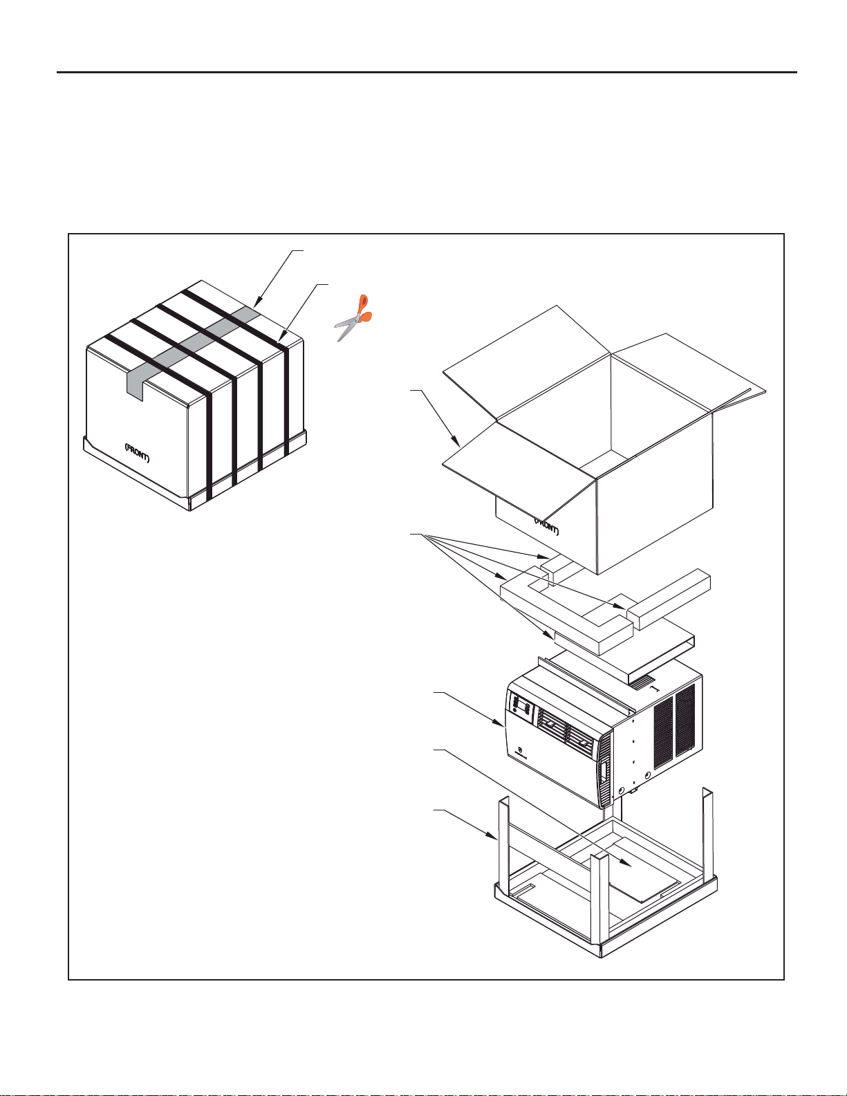
STEP 1. CUT ALL PACKING STRAPS.
STEP 2. CUT TAPE AND OPEN.
STEP 3. REMOVE TOP PACKAGING M ATERIAL AND CA RTON
CONTAINING SIDE CURTAINS.
STEP 2
STEP 1
STRAPS X4
STEP 4
STEP 4. SLOWLY REMOVE OUTER BOX.
STEP 5. REMOVE CORNER POSTS.
STEP 6. REMOVE UNIT FROM SHIPPING TRAY.
STEP 7. REMOVE CARBON FILTER AND HARDWARE FROM
BOTTOM TRAY.
STEP 3
STEP 6
STEP 7
STEP 5
5
Page 6
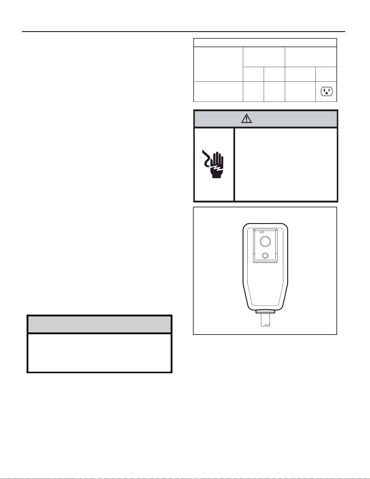
WARNING : Before Operating Y our Unit
Make sure the wiring is adequate for your unit.
If you have fuses, they should be of the time delay type. Before you install
or relocate this unit, be sure that the amperage rating of the circui t breaker
or time delay fuse does not exceed the amp rating listed in Table 1.
DO NOT use an extension cord.
The cord provided will carry the proper amount of electrical power to the
unit; an extension cord may not.
Table 1.
MODEL
SQ05 SQ06
SQ08 SQ10
EQ08
CIRCUIT RATING
OR TIME DELA Y
FUSE
AMP VOLT NEMA NO .
15 125 5-15P
REQUIRED WALL
RECEPTACLE
Make sure that the receptacle is compatible with the air
conditioner cord plug provided.
This insures proper groun ding. If you have a two pro ng receptac le you
will need to have it replaced with a grounded receptacle by a certi¿ ed
electrici an. The grou nded rec eptac le should m eet all national an d local
codes and ordinances. U nder no c irc umstanc es sh ould you r emove the
ground prong from the plug. Y ou must use the three prong plug furnished
with the air conditioner.
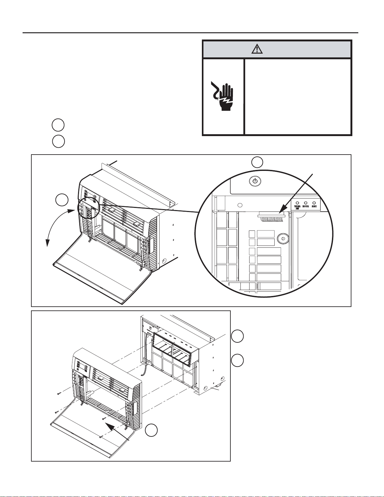
T est the power cord
All Friedrich roo m air conditioners are shippe d from the factor y with a
Leakage Current Detection Interrupter (LCDI) equipped power cord. The
LCDI device meets the UL and NEC requirements for cord connected air
conditioners effective August 2004.
To test your power supply cord:
1. Plug power supply cord into a grounded 3 prong outlet.
2. Press RESET (See Figure 1).
3. Press TEST, listen for click; the RESET button trips and pops out.
4. Press and release RESET (Listen for click; RESET button latches
and remains in
Once plugged in, the unit will operate normally without the need to reset
the LCDI device.
If the LCDI device fails to trip when tested or if the power supply cord is
damaged, it must be replaced with a new power supply cord from the
To expedite service, please have your model number available.
). The power cord is ready for use.
WARNING
Electrical Shock Hazard
Make sure your electrical receptacle has the
same configuration as your air conditioner’s
plug. If different, consult a Licensed Electrician.
Do not use plug adapters.
Do not use an extension cord.
Do not remove ground prong.
Always plug into a grounded 3 prong oulet.
Failure to follow these instructions can result in
death, fire, or electrical shock.
Figure 1
RESET
TEST
WARNING:
TEST BEFORE EACH USE!
1.PRESS REST BUTTON.
2.PLUG LCDI INTO POWER
RECEPTACLE.
3.PRESS TEST BUTTON,
RESET BUTTON SHOULD
POP UP.
4.PRESS RESET BUTTON
FOR USE.
DO NOT USE IF ABOVE TEST
FAILS .
WHEN GREEN LIGHT IS ON.
.5466-145 )008( ta eniL ecnatsissA lacinhceT ruo tcatnoC .rerutcafunam
IT IS WORKING
PROPERLY!
NOTICE
Do not use the LCDI device as an ON/OFF switch.
Failure to adhere to this precaution may cause
premature equipment malfunction.
6
FRR072
Page 7
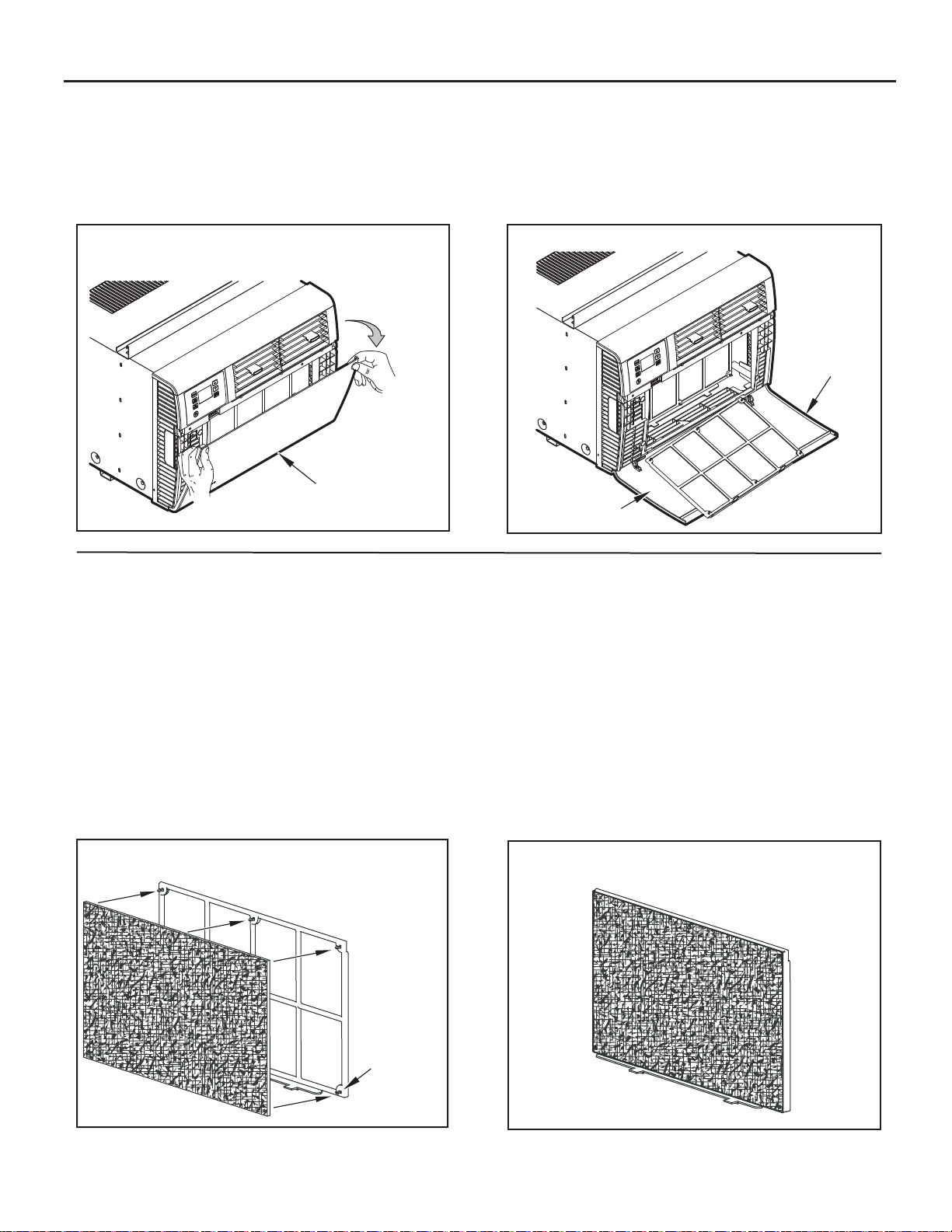
Standard Filter Cleaning / Installation Instructions
STEP 1. Swing the door op en and remove the fi lter by grasping the
fi lter grip and pushing the fi lter holder upward and outward.
Figure 2
FILTER
DOOR
FRR075
Premium Carbon Filter Installation Instructions
STEP 2. Clean the front frame by washing the dirt from the fi lter. Use a
mild soap solution if necessary. Allow fi lter to dry.
STEP 3. Install the fi lter back into the unit. Follow the Instr uctio ns on
the inside of the front door.
Figure 3
FILTER
DOOR
FILTER FRAME
INSTRUCTIONS
FRR076
Please follow the instructions below to install the Friedrich carbon fi lter. The carbon
fi lter should be replaced after 300 hours of operation, 3 months, or more often if
needed for maximum effectiveness.
When you replace the carbon fi lter, clean the washable mesh fi lter if dirty. Allow
mesh fi lter to dry before reinserting.
STEP 1. Remove the black plastic fi lter frame from the unit following the
instructions on the inside of t he fi lter door. (Washable mesh
fi lter is included and is permanently attached to fi lter frame).
STEP 2. Lay the black plasti c fi lter frame on a fl at surface, with the 6
fi lter frame hooks facing upward.
Figure 4
FILTER FRAME
HOOKS (6)
Place the carbon fi lter over the fi lter frame so that the carbon
fi lter’s 6 installation holes align with the 6 fi lter frame hooks.
(Figure 4)
Secure the carbon fi lter to th e fi lter frame. Make sure that
all 6 fi lter frame hooks are inserted through all 6 inst allation
holes of the ca rb on fi lter. The installation hooks will ho ld the
fi lter securely.
STEP 3. Place the black plasti c filter frame with the carb on filter
installed (Figure 5) back into the fr ont of the unit, following
the instructions on the inside of the fi lter door.
Carbon fi lter is now ready for use!
Figure 5
FRR077
FRR078
7
Page 8
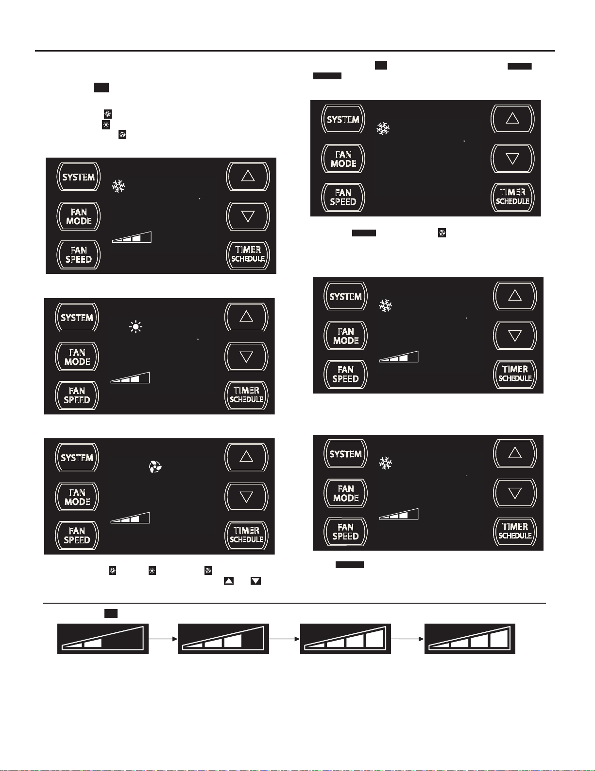
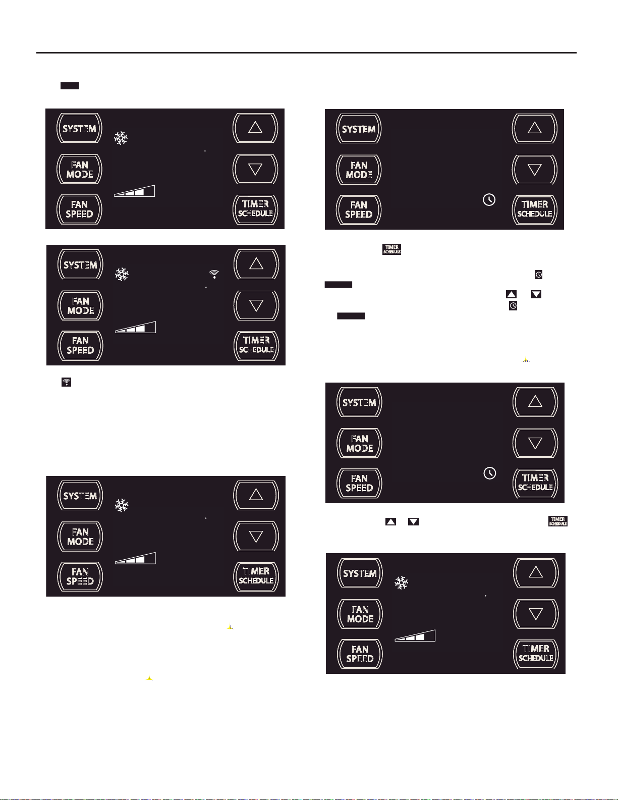
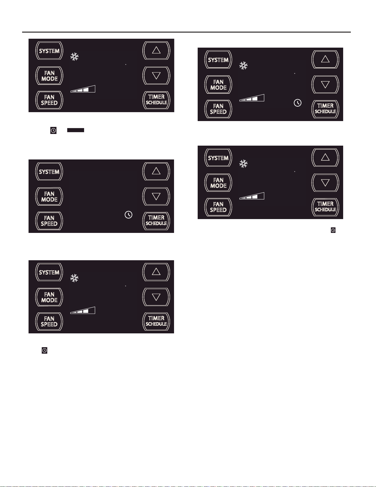
Control Panel Operation
Let’s check out how to control your air conditioner. On the control panel, just above the POWER , is a liquid crystal display (LCD). All of the control panel function
buttons and mode icons can be viewed in Figure 6.
Power On – Pres s the but to n to tur n on the air c on ditio ner. The power button illuminates to indic ate th at the p ower is on. The bac klig ht on the power switch
will automatically dim to 20% intensity after 15 seconds of inactivity. The remote contr
Display – The display is a high ef¿ ciency LCD with a built-in white bac klight . The back light has an automatic t wo (2) step dim functi on. Af ter 15 seconds of
inactivity, the display dims to 20% intensity. After an additional 120 seconds, th e display switc h es off. Touching any button a uto mat ically changes the display
to full brightness.
There are three control push buttons on each side of the display.
ol can also be used to turn power ON / OFF (See Remote Control).
Figure 6
SYSTEM:
Cycles between
HEAT, COOL or
FAN ONLY
FAN MODE:
Sets fan to either:
- Cycle automatically
- Run continuously
FAN SPEED:
Sets fan speed:
LOW, MED, HIGH
or AUTO
(as equipped)
ON / OFF:
Turns unit on/off
COOL
FAN SPEED
Selected fan speed
HEAT
AUTO FAN
CONTINUOUS
FAN
ONLY
AUTO SPEED
AUTO SPEED
Automatically selects
best fan cooling speed
CONTROL
LOCKED
88
SET POINT
ROOM TEMP
CHECK $MART
FILTER
FILTER
Check / Clean
WI-FI
OPERATING (if equipped)
F
C
AM
PM
ON OFF
SCHEDULE
2 DIGIT DISPLAY
Shows Setting for:
- Set Point (Temperature)
- Room Temperature
- Clock (AM/PM)
$MART OPERATING
(if equipped)
TEMPERATURE:
Increment UP
WAIT
TEMPERATURE:
Increment DOWN
SCHEDULE ON
TIMER / SCHEDULE
Turns ON or OFF
TIMER ON
IR WINDOW:
Do not block
FRR079
8
Page 9
Kühl Control Options
The
Kühl gives you a variety of options for control, programming, and
scheduling including wireless capabilities
Wireless Programming and Control:
The new FriedrichLink™ Adapter (sold seperately) allows you to conviently
control, program and monitor your air conditioning unit remotely from a
smartphone or computer.
FriedrichLink™ Adapter accessory available through Friedrich authorized
retailers or www.friedrich.com. See FriedrichLink™ Adapter section on
www.friedrich.com for complete details.
Pre-Programmed Scheduling Options:
Your unit’s digital control comes equipped with a 24-hour timer and two preprogrammed 7-day energy management options.
24-Hour Timer
The 24-hour t imer allows you to turn the unit of f and on at pre- set times by
setting an on and off time on the u nit control pan el. ( See pa ge 11 for details on
timer set-up. )
Pre-programmed Energy Management
Your unit comes from the factory with two (2) Pre-programmed
Management settings are shown in Addendum 1 (Residential & Commercial
Schedule T able ) .
Energy Management Schedule Options are:
1. Residential Schedule – 40 Hr. Work Week
2. Commercial Schedule – 5-Day Business Week
Energy
The “Residential” (40 Hr. Work Week ) Schedule has four (4 ) time periods: 06:00,
08:00, 18:00, and 22:00. This option will cause your Kühl Q unit to raise the room
temperature temporarily to 85°F during the hours wh
at work, lower them again to 78°F prior to the time when most people will return
home, and then raise slight ly to 82°F to maintain a comf ortabl e temperature
overnight.
The “Commercial” (5-Day Business Week) Schedule has two (2) time periods:
07:00 and 18:00. This option will cause your air conditioner to raise temperatures
to 84°F after typical working hours and on weekends when commercial spaces
ar
e typically unoccupied.
(See Control Panel Operation Instructions Section)
en most people are away
Customizable Pr ogramming Options :
Customizable schedules, with up to four temperature adjustments per day, can
either be uploaded to the unit via the air conditioner’s built-in micro USB interface
or conveniently transmitted wirelessly using the n ew Friedric hLink™ Adapter
accessory, greatly simplifying the programming of one or multiple units.
See Figure 7.
See ww w.friedrich.com for complete Customizable
Programming instructions.
Figure 7
FRR203
9
Page 10
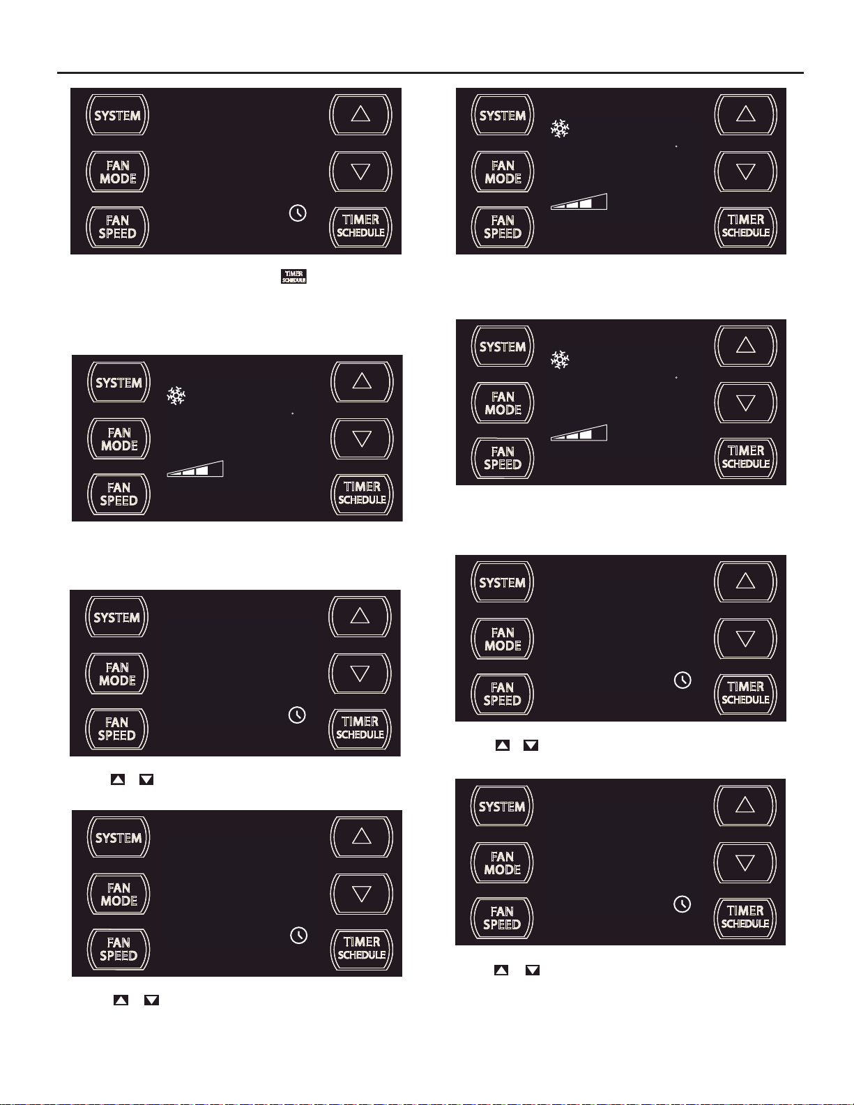
Control Panel Operation Instructions
SYSTEM - The
of operation:
SYSTEM
button allows you to sequentially select three modes
COOL
HEAT Not available on some models
FAN ONLY
COOL MODE
FAN MOD E – Th e
CONTINUOUS
modes.
FAN
MODE
button allows you to select between
AUTO FAN (No Cooling Demand)
AUTO FAN
79
SET POINT
F
AUTO FAN
and
AUTO FAN
HEAT MODE
AUTO FAN
FAN ONLY MODE
74
SET POINT
68
SET POINT
F
FRR112
When in the
a demand to cool or heat the room. Note: the fan is off (no fan speed icon),
indicating no command for cooling or heating.
FRR103
F
System has a demand for cooling. The fan is operating at a medium speed.
FRR104
AUTO FAN
mode, the fan only operates when the system has
AUTO FAN (Cooling Demand)
AUTO FAN
CONTINUOUS
CONTINUOUS
74
SET POINT
79
SET POINT
F
F
FRR106
FRR105
When in the COOL or HEAT or FAN ONLY mode, you c an a lso
select FAN MODE, FAN SPEED, TIMER SC HEDULE,
SYSTEM MODE does not change.
FAN SPEED - The
3 Speed
When fan speed AUTO mode (SYSTEM mode COO L or HE AT) is selected, fan spe ed automatic ally varies d epending on t he dif ferenc e bet ween the unit 's
set point on the control panel and the actual room temperature. Let me explain. Say for example, you’re working in your garage and you open the big door for
several minutes. The system will se nse a wide dif fere nce bet ween the s et point and the ac tual room te mperature. W hen this oc cur s, the system f an speed
increases to HIGH for a period of time. The fan speed decreases, in step, as the temperature difference decreases. When the room temperature matches the
system's set point, fan speed returns to the original setting.
10
FAN
button allows you to toggle between four modes of operation: LOW, MEDIUM, HIGH and AUTO.
SPEED
and . The
CONTINUOUS
In the
periodically cools or heats the fan's airfl ow but the fl ow of air does not stop.
fan mode, the fan op erates all the time. The system
AUTO
FRR113
FRR095
Page 11
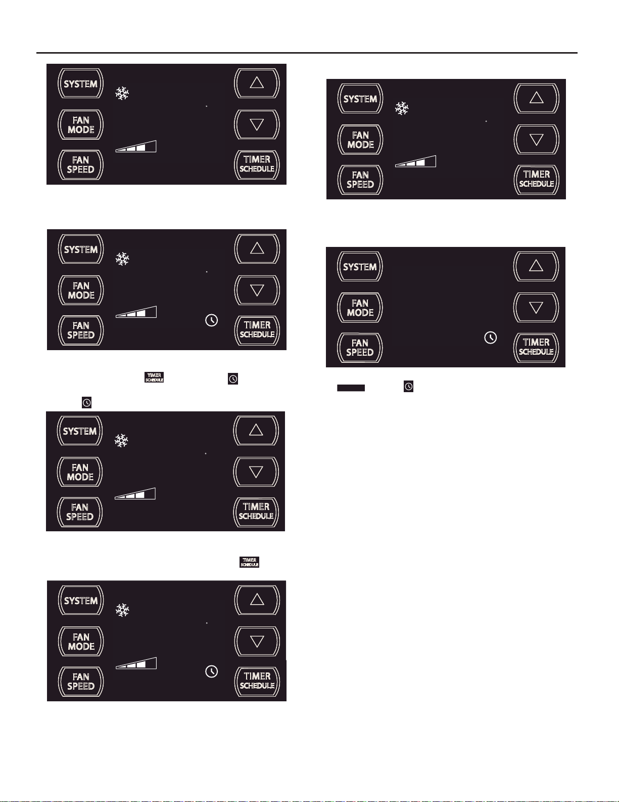
UP and DOWN - arrows - Pressing either or button changes
the system's set point (desired room temperature). These buttons are also
used to make system parameter changes later in this manual.
AUTO FAN
74
SET POINT
F
FRR100
The icon illuminates.
The TIMER function (option 1, system default) allows you to de¿ ne a daily
system ON and OFF time win dow. For example, you can command t he
system to turn ON at 8:15 am and turn OFF at 1:30 pm everyday.
The SCHEDULE function allows you to choose either Residential (option
2) or Commercial (option 3). The Residential and Commercial options are
described later in this manual.
OTHER FUNCTIONS
Figure 8
AUTO FAN
75
SET POINT
One press equals 1 degree of change. Ho l ding the button down for more
than 0.6 seconds star ts t he fast increment /decrement c hange of the set
point.
TIMER SCHEDULE - The
SCHEDULE
or
The
function.
button selected during a preset OFF time.
button allows you to select the TIMER
F
FRR101
FRIEDRICH
AIR CONDITIONING CO.
SAN ANTONIO, TX
FRR097
SET TIME- To adjust the unit's time press and hold the HOUR and the MIN
buttons for three seconds (Refer to Figure 8).
AM
11
FRR128
The unit's curre nt hour displays. Use the or buttons to adjust the
hour. To change from AM to PM continue to increment (roll) the display.
Press TIMER SET (Refer to Figur e 8) button to display th e unit 's cur rent
minutes.
The icon illuminates.
The
button selected during a preset ON time.
AUTO FAN
79
SET POINT
FRR122
25
F
FRR129
Use the or b uttons to adjust the minutes. T he clock is now set
for 11:25 AM. Press TIMER S E T (Refe r to Figur e 8) but t on to disp lay th e
unit's day setting.
FRR123
11
Page 12
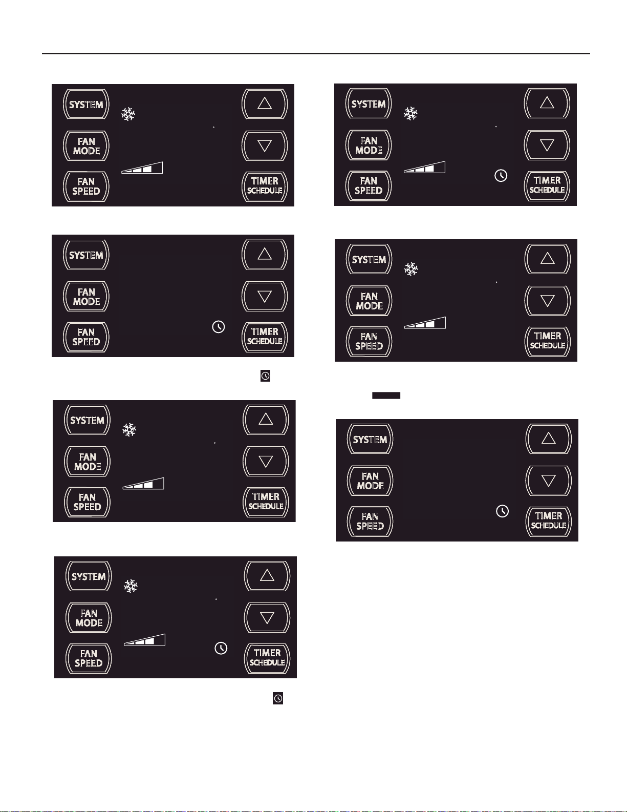
4
s
C
FRR130
Use the or buttons to adjust the day (1 to 7). The day setting is up
to you the user. If you set the curre nt day = 1, and today is Tuesday,
then Day 1 = Tuesday.
AUTO FAN
79
SET POINT
Press TIMER SET (Ref er to Figure 8) button to exit and save the SET
TIME function. The TIMER SET button must be pressed within 15 second.
Button inactivity for more than 15 seconds causes the display to time out
and return to the normal operating display.
ºF - ºC Select
AUTO FAN
79
SET POINT
F
FRR131
F
FRR134
A “C” will À ash for 5 seconds and then revert to a normal display.
AUTO FAN
26
SET POINT
The ºF icon goes away and the ºC icon illuminates on the normal display.
DIM Function
There are three separ ate display brightnes s levels, AUTO, 20% and full
(100%). To change the DIM setting, pr ess the Power button for thr ee
seconds.
C
FRR135
1
FRR192
FRR132
To switch from degrees Fahrenheit (F) to Celsius (C), press
buttons simultaneously for three seconds.
and
f
FRR133
An “F” will
À ash for 5 seconds and then revert to a normal display. T o change
from F to C, press the
12
or button within 5 seconds.
The 1 indicates a DIM setting of Auto (factory default). Use the or
buttons to change the setting.
2
FRR193
The 2 indicates a DIM setting of 20%. Press the TIMER SET button within
15 seconds to save the setting. Button inactivity for more than 15 seconds
causes the display to time out and return to the normal operating display.
Page 13
3
FRR194
The 3 indicates a DIM setting of 100% (full brightness). Press the TIMER
SET (Refer to Figure 8) button within 15 seconds to save the setting.
Button inactivity for more than 15 seconds causes the display to time out
and return to the normal operating display.
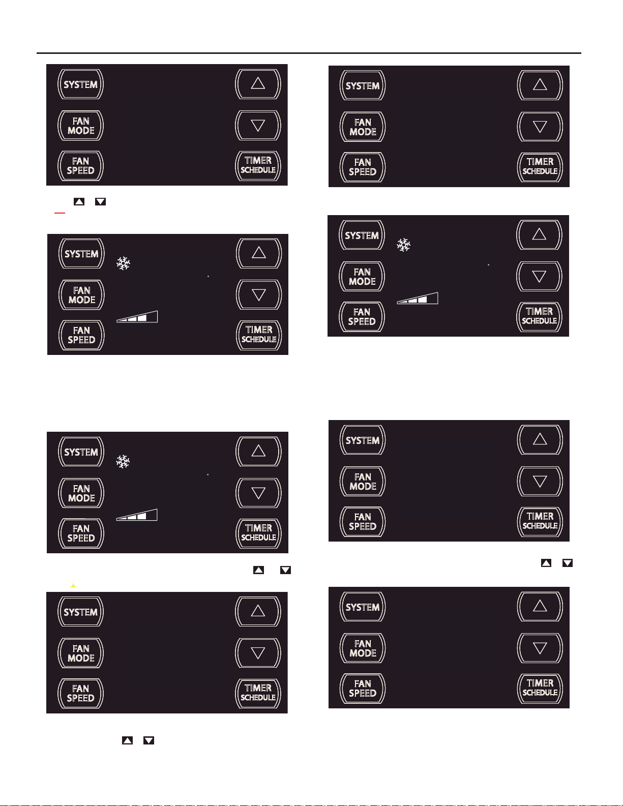
This means there is a compressor demand but the system is not ready
for the compr essor to operate. For example a sho rt power outag e, the
compressor will not restart until the internal pressures of the compressor
are at the proper level.
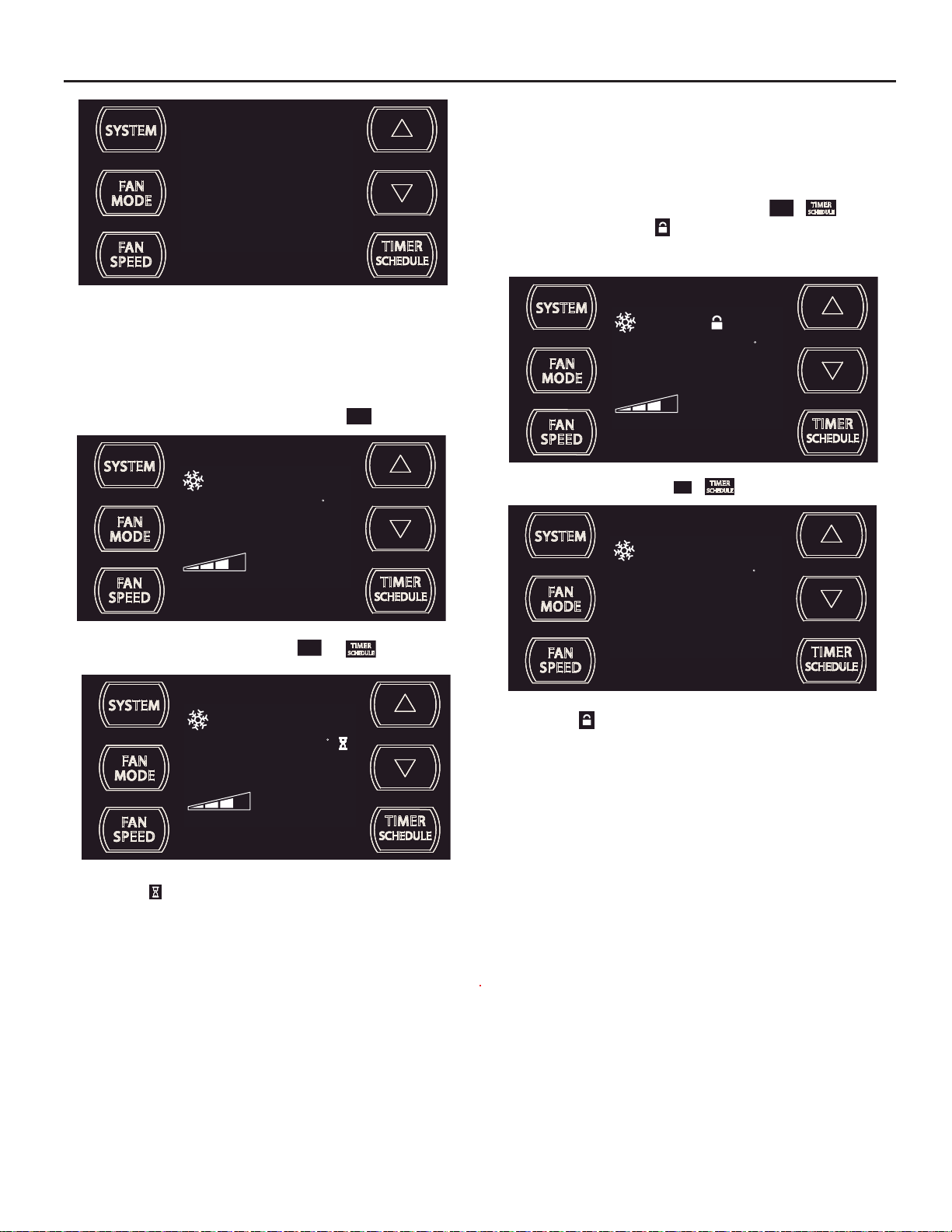
Lock Control Panel
To lock the front panel controls, press and hold the
for 3 seconds. The lock icon
Control panel buttons will not operate during lockout.
AUTO FAN
illuminates to indicate the locked status.
FAN
+ buttons
SPEED
F
Alerts
When the ¿ lter needs to be cleaned or replaced, the
AUTO FAN
79
SET POINT
CHECK
FILTER
The alert can be dismissed by pressing the
AUTO FAN
79
SET POINT
F
FAN
MODE
and for 3 seconds.
F
CHECK
icon displays.
FILTER
FRR118
79
SET POINT
FAN
To unlock, presses and hold the
AUTO FAN
The lock icon disappears to indicate unlocked status.
SPEED
+ buttons for 3 seconds.
F
79
SET POINT
FRR116
FRR117
FRR120
The wait icon illuminates when the compressor 3 minute time delay is
active.
13
Page 14
External Control Status
op
$MART
The
remotely.
icon illuminates to indicate that the system is being controlled
Commercial (Schedule #2)
programmed set of op er ati onal par ameter s t hat c over s 7 days of
the week with 2 time windows during each day. Each time window
has it's own set of 6 operating para meters. Refer to Addendum.
- When selected the unit f ollows a pre-
AUTO FAN
79
SET POINT
AUTO FAN
79
SET POINT
The ic on illuminates to indicate t hat the system is recei ving a Wi- Fi
connection.
ADVANCED FUNCTIONS
Your unit's advanced functions (Timer, Schedule, Test Mode, and Maintenance Menu). The functions mentioned in the following section may or may
not be available depending on the air conditioner model.
Timer/Schedule Select
F
$MART
FRR125
F
FRR126
1
T1. o change the select ion, press and hold t he TIMER /SCHEDULE
button for 3 sec.
If the Schedule function is available, the system displays the
SCHEDULE
icon. The display indicates the sc hedule f unct io n that is ac tive.
To change to an alternate schedule (2 or 3), press the
If the Schedule function is not available, the Timer icon
SCHEDULE
the
To save and exit this selection, press the TIMER SET button for 3 sec.
(Figure 8).
If there is no button activity for 15 seconds, the function will time out and
leave the original selection. Once the selection is saved or timed out, the
display reverts to the normal display.
icon.
2
SCHEDULE
FRR137
or button.
shows without
SCHEDULE
+ noci
AUTO FAN
79
SET POINT
The control system has:
Timer (factory default) - Allows you to command the unit to turn
ON and OFF at time you pro g r am w it h in a 7 day wind ow. Sett ing
the start, stop and day window can be found later in this manual.
Residential (Schedule #1) - When selected the unit follows a
preprogrammed set of operational parameters that covers 7 days
of the week with 4 time windows during each day. Each time
window has it's own set of 6 operating parameters. Refer to
Addendum.
14
F
FRR136
FRR138
After pressing the or button, within 15 second of pressing the
button for 3 second s, the display indic ates a chang e to Timer/S chedule r
2. To save and exit this selection, press the TIMER SET button (Figure 8).
AUTO FAN
79
SET POINT
The display reverts to the normal display.
F
FRR136
Page 15
AUTO FAN
79
SET POINT
F
FRR139
To turn on the timer or schedule selected, press button and let go, the
system will operate in the mode (1, 2 or 3) you selected.
Modify the TIMER Function
Timer Start Time
AUTO FAN
79
SET POINT
The display shows a norma l system. Press and hold the H OUR button
(Figure 8) for 3 seconds. Note the Timer start-stop times may be set even
when the system is in the Timer or Schedule mode.
4
F
FRR140
AM
ON
FRR143
The display returns to normal once the settings are saved.
Timer Stop Time
AUTO FAN
79
SET POINT
The display shows a normal system. Press and hold the MIN button (Figure
8) for 3 seconds. Note the Timer start - stop times may be set even when
the system is in the Schedule mode.
11
F
FRR144
AM
OFF
FRR141
Use the or button to adjust the hour. Press the TIMER SET button
(Figure 8) to adjust the minutes.
21
Use the or b utton to adjust the minute s. Press the TIM ER SET
button (Figure 8) within 15 seconds to exit and save the setting. The timer
is now set to start at 4:21 AM.
ON
FRR142
FRR145
Use the or button to adjust the hour. Press the TIMER SET button
(Figure 8) to advace to the minutes section.
55
Use the or but ton to adjust the minutes. Press t he TIMER SET
button (Figure 8) within 15 seconds to exit and save the setting. The timer
is now set to stop at 11:55 AM.
OFF
FRR146
15
Page 16
SET POINT
F
AUTO FAN
79
SCHEDULE
FRR149
Schedule ON Scenarios
AUTO FAN
79
SET POINT
The display returns to normal once the settings are saved.
Timer - Scheduler Control Block
AUTO FAN
79
SET POINT
If the unit is operating in th e TIM ER or SCH EDU LE mod e, and then yo u
press any button except t he
blink. All button action is blocked.
The Timer icon stops blinking after 3 seconds.
button, the Timer icon begins to
F
FRR147
F
SCHEDULE
FRR148
AUTO FAN
79
SET POINT
The display shows a normal system.
If the Schedule function is turned ON during normal operation
SCHEDULE
the
runs the
and Timer i
current period schedule parameters.
cons illuminates. The control system immediately
F
SCHEDULE
FRR154
FRR153
AUTO FAN
79
SET POINT
You must turn the active Timer or Schedule mode OFF before making
changes. Once the changes are made, press the button to reactivate Timer or Schedule mode.
Timer or schedule mode reactivated.
16
F
FRR150
Page 17
Timer ON Scenarios
Scheduler OFF Scenarios
AUTO FAN
79
SET POINT
The display shows a normal system.
If the Timer function is turned ON during the Off time, the icon
illuminates. The control system immediately turns the unit OFF.
F
FRR156
FRR157
AUTO FAN
79
SET POINT
The display shows the unit in Schedule mode.
AUTO FAN
79
SET POINT
Timer and
The display shows a normal system.
SCHEDULE
icons turn of f. The c ontrol st ays in the cur rent st ate.
F
SCHEDULE
FRR160
F
FRR161
eht ,)ffo ton( etats evitca na gnirud FFO denrut si noitcnuf eludehcS eht fI
AUTO FAN
79
SET POINT
The display shows a normal system.
AUTO FAN
79
SET POINT
If the Timer function is turned ON during the ON time, the Timer
illuminates. The control system continues to run.
F
F
SCHEDULE
FRR158
FRR162
The display shows the unit in Schedule mo de during an in- active (OFF)
period.
FRR159
noci
17
Page 18
Scenario 2:
AUTO FAN
79
SET POINT
If the Schedule funct ion is tur ned OFF dur ing an in- active (OFF) p erio d,
the Timer
known non-schedule state.
Timer OFF Scenarios
Scenario 1:
The display shows the unit in Timer mode during an in-active (OFF) period.
and
SCHEDULE
icons turn of f. The unit wakes up in the last
F
FRR163
FRR166
AUTO FAN
79
SET POINT
The display shows the unit in Timer mode during an active (ON) period.
AUTO FAN
79
SET POINT
If the Timer function is turned OFF durin g the ON time . Th e Timer
turns off. The control stays in the current state.
The display shows a normal system.
F
FRR168
F
FRR169
icon
AUTO FAN
79
SET POINT
If the Timer functi on is tur ned OFF dur ing an in -ac tive (OFF) per io d, the
Timer
18
icon turns off. The display shows a normal system.
F
FRR167
Page 19
Remote Control Operation
Remote Control - Refer to Figures 10 and 11 during operation description.
Getting Started - Install two (2) AAA batteries in the battery compartment
located on the back of the unit.
Operation - The re mote control should be within 25 feet of t he air
conditione r f o r o p e r ation. (Refer to Figure 9 for effec tiveness). Press the
power button to tur n the rem ote on. The re mote will autom atic ally power
off after 15 seconds if the buttons are not being pressed. The remote must
be on to control the unit.
POWER Button - Turns remote and unit on and off.
SYSTEM B utton - Allows the user to sequentially select, Cool
HEAT
display indicates which mode has been se lected via a disp lay message.
Note that when the heating function is not available, the system will
automatically skip the HEAT mode.
FAN MODE Button - Selects between automatic (
operation. In the
compressor operates or the heat function is enabled.
NOTE:
, and FAN ONLY operation. When the button is pressed, the
AUTO FAN
mode, the fan only tur ns o n and off when the
AUTO FAN
is not available in the FAN ONLY Mode, the display
indicates
CONTINUOUS
. In the
CONTINUOUS
determined by your selection on the
AUTO FAN
mode, fan speed is
FAN
button.
SPEED
CONTINUOUS
) or
FAN SPEED Butto n - Used to sequentially selec t new fan speed, plus
AUTO operation. When the
FAN
button is pres sed, the fan spe ed icon
SPEED
(triangle) changes to indicate the new speed level. Fan speed automatically
varies depending on the set temperature on the control panel and the actual
room temperature. For example if there is a bi g difference between your
set temperature and the ac tual r oom tem per ature, the syste m fan spe ed
increases to HIGH. It r emains at this speed unt il the room temper ature
matches the set temperature.
SCHEDULE Button – The
SCHEDULE
button turns the schedul e funct ion
on and off. Press the Schedule button once to turn on the Schedule
(Residential, Commerc ial, Timer, or Customized) that has already been
selected on your unit. Pressing the
,
the schedule function off.
UP and DOWN Arrows - Pressing either the
SCHEDULE
button a second time turns
(UP) or (DOWN)
button change s th e de sir ed r o om tem pe rat ure. Th e fac to ry preset lower
and upper limits are 60°F (16°C) and 99°F (37°C). These buttons are also
used to navigate between function options when using t h e Us er Menu or
Maintenance Mode.
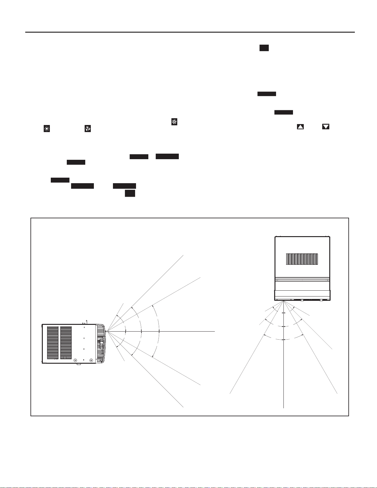
Remote Effectiveness
Hand Held Re mote - Has an operating range of up to 25 ft. The infrared
remote control signal must have a clear path to transmit the command to
the air conditioning unit. The re mote signal has some abilit y to "b ounce"
off of walls and furniture similar to a television remote control. The diagram
below shows the typical operating range of the control in a standard room
with 8 ft high ceilings.
Figure 9
SIDE VIEW
TOP VIEW
25ft
25ft
7.5ft
30°
45°
60°
60°
45°
30°
8ft
25ft
25ft
25ft
4ft
8ft
60°
60°
45°
45°
30°
30°
6ft
16ft
25ft
25ft
25ft
FRR080
19
Page 20
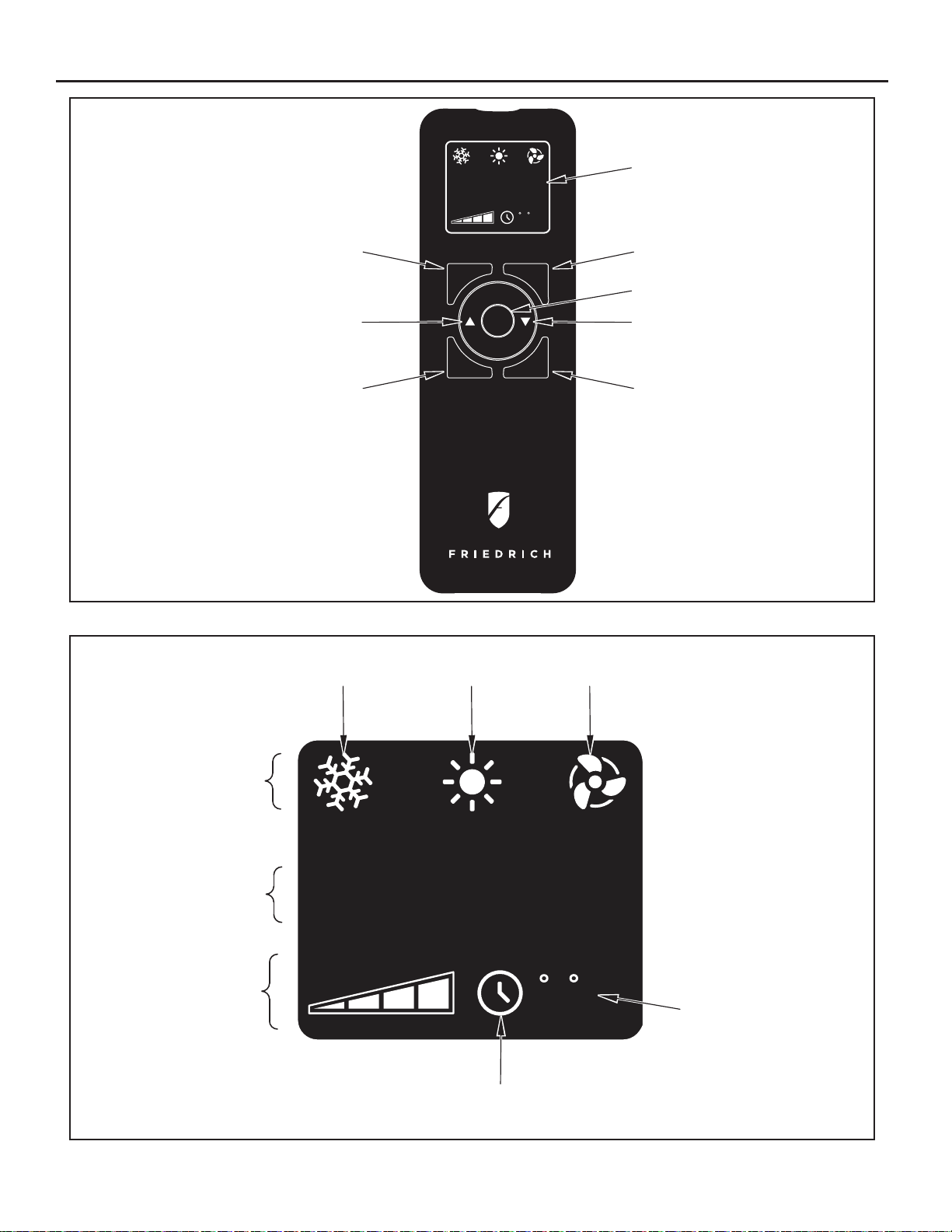
Figure 10
SYSTEM
TEMPERATURE
UP
FAN SPEED
AUTO FAN
CONTINUOUS
AUTO
SYSTEM
FAN SPEED
88
FAN MODE
POWER
SCHEDULE
DISPLAY
F
C
FAN MODE
POWER
TEMPERATURE
DOWN
SCHEDULE
FRR081
Figure 1 1
SYSTEM
MODE
FAN
MODE
FAN
SPEED
COOL
ICON
AUTO FAN
CONTINUOUS
AUTO
HEAT
ICON
FAN ONLY
ICON
88
F
C
SCHEDULE
ICON
°F / °C
ICONs
FRR082
20
Page 21
AirÁ ow Selection and Adjustment
AirÁ ow direction adjustment
The airÀ ow path may be adjusted to distribute air independently from the
left or right side of the disc harge opening. Eac h of the banks of louver s
can be directed left, right, up or down in order to achieve the most optimum
airÀ ow positioning.
To adjust airÀ ow direction grab the lever in the center of the louver bank and
move it in the direction that you wo uld like the air to be direc ted. Please
note that it is normal
louvers than the other.
that airÀ ow may be stronger out of one side of the
Installation Instructions
Figure 12
LEFT AIRFLOW
LEVER
RIGHT AIRFLOW
LEVER
FRR083
WARNING
Electrical Shock Hazard
Make sure your electrical receptacle has the
same configuration as your air conditioner’s
plug. If different, consult a Licensed Electrician.
Do not use plug adapters.
Do not use an extension cord.
Do not remove ground prong.
Always plug into a grounded 3 prong oulet.
Failure to follow these instructions can result in
death, fire, or electrical shock.
READ THIS FIRST! Electrical Requirements
IMPORTANT: Before you begin the actual installation of the air conditioner,
be sure your electrical requirements are as described below. Consult an
electrical professional as necessary to insure home wiring is per local
electrical codes.
CIRCUIT PROTECT ION – An overloaded circuit will invariably cause
malfunction or failure of an air conditioner , therefore, it is necessary that the
electrical protection is
when your air conditioner is started, use a "TIME DELAY" fuse or a HACR
type circuit breaker. Consult your dealer or power company if in doubt.
Your air conditioner must be connected to a power supply w it h the s am e
A.C. voltage and hertz as marked on the unit nameplate. Only alternating
current (A.C.), no direct current (D.C.), can be used.
The power cord has a plug with a grounding prong of approved type and a
ma
tching plug receptacle with ground is required. Refer to page 6 for the
correct type of plug receptacle for your model.
adequate. Due to momentary high current demand
21
Page 22
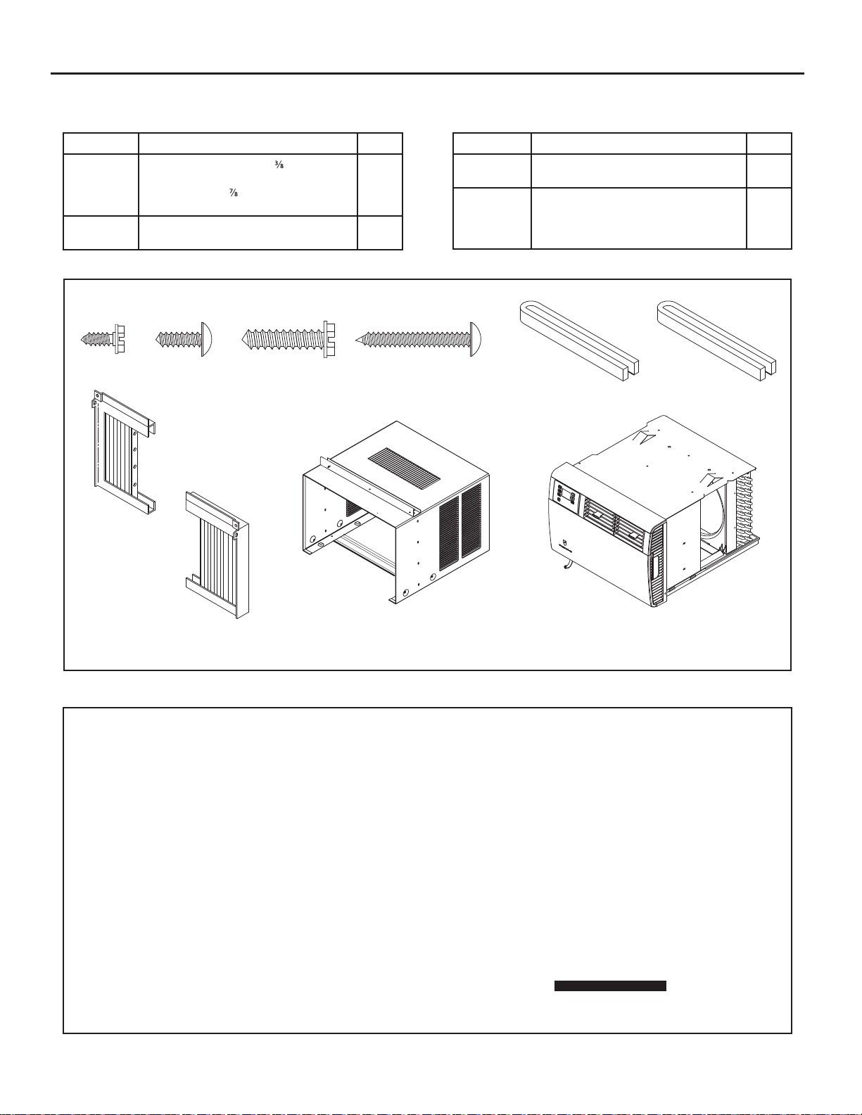
Items required for installation (provided in straight cooling units only)
ITEM NO DESCRIPTION QTY.
1
2
3
4
5
6
ITEM #1
ITEM #7
SCREW, SHEET METAL, #8 x "
SCREW, PHILLIPS, TRUSS HEAD, #8 x ½"
SCREW, HEX, #8 x
SCREW, PHILLIPS, #8 x 1 ¼"
GRAY GASKET, FOAM, 1" x 1 ½" x 42"
WHITE GASKET, FOAM, 1" x 1 ½" x 48"
ITEM #2
"
ITEM #3
8
4
10
2
1
1
ITEM #4
ITEM NO DESCRIPTION QTY.
7
8
9
10
LEFT SIDE CURTAIN ASSEMBLY
RIGHT SIDE CURTAIN ASSEMBLY
CABINET OR SLEEVE w/ TOP ANGLE BAR
(TOP ANGLE BAR NOT INCLUDED ON EQ)
AIR CONDITIONING UNIT w/ DECORATIVE
FRONT PANEL
ITEM #5
ITEM #6
1
1
1
1
1
ITEM #8
ITEMS NOT TO SCALE
ITEM #9
Recommended tools required for installation: (not included)
HEXHEAD SCREWDRIVER
COMMON SCREWDRIVER
ITEM #10
FRR084
PHILLIPS SCREWDRIVER
22
Page 23
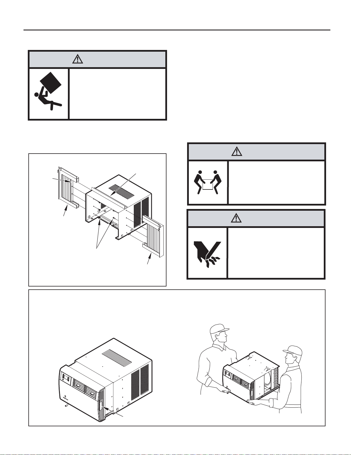
Standard Window Installation
A
STEP 3. Center cabinet in window with sill channel positioned against
window stool as shown in Figure 15, Section A-A.
WARNING
Falling Object Hazard
Not following Installation Instructions
for mounting your air conditioner can
result in property damage, injury, or
death.
STEP 1. After removing the unit from shipping carton, (See Figure 14).
STEP 2. Attach cur tain as sembli es to cabinet as sh own in Figure 13.
Figure 1 3
CURTAIN
SSEMBLY
RETAINING
BRACKET
Use eight (8) No. 8 x 3/8" slot ted hex head scr ews (item #1,
page 22).
SHELL SUPPORT
CHANNEL
CURTAIN
ASSEMBLY
(LEFT)
SCREW #8 x 3/8” SLOTTED HEX HEAD
(ILLUSTRATION ON PAGE 22, ITEM #1)
8 REQUIRED (4 EACH SIDE). INSTALL
FROM INSIDE SLEEVE TO CURTAIN
ASSEMBLY RETAINING BRACKET.
ASSEMBLY
CURTAIN
(RIGHT)
FRR085
STEP 4. Pull window sash down behind Shell Support Channel on top
of cabinet; this helps h old cabinet in plac e. Install No. 8 x "
hex head screw (item #3, page 22) in sill channel at bottom of
window opening as shown in Figure 15.
STEP 5. Extend the sliding curtains on each side so the frames fi t into
the window channels. While hol ding the curtain frames in
place, mark four (4) hole locati ons (hole l ocati ons are in the
upper corners on left and right curtain assembly), two (2) in the
window jamb and two (2) in the window sash. Slip the curtains
back from marked loc ations and dr ill four (4) 7/64" diameter
pilot holes. Again, extend the sliding cur tains on each side
and then install two (2) No. 8 x ½" Phillips head screws (item
#2, page 22) and two (2) No. 8 x 1 ¼" Phillips head screws
(item #4) through the curtain frames as shown in Figure 15.
CAUTION
Excessive Weight Hazard
Use two or more people when
installing your air conditioner.
Failure to do so can result in
back or other injury.
CAUTION
Cut/Sever
Although great care has been
taken to minimize sharp edges
in the construction of your unit,
use gloves or other hand
protection when handling unit
Failure to do so can result in minor
to moderate personal injury.
Figure 1 4
TO PULL UNIT FROM SLEEVE, USE THE SIDE HANDLES
LOCATED ON EITHER SIDE OF THE UNIT DECORATIVE
FRONT. OBTAIN ASSISTANCE OR HELP AS NECESSARY
TO HOLD SLEEVE WHILE PULLING UNIT FROM SLEEVE.
MAKE SURE AIR CONDITIONER IS ON FIRM SUPPORT
BEFORE REMOVING UNIT FROM SLEEVE.
SIDE HANDLE
WHEN CARRYING OR HANDLING UNIT, OBTAIN ASSISTANCE
OR HELP AS NECESSARY TO SUPPORT UNIT FROM BOTTOM
(BASEPAN), MAINTAINING CLEARANCE FROM ALL OBSTACLES.
FRR086
23
Page 24
Figure 1 5
SHELL SUPPORT CHANNEL
SCREW, 1/2” PHILLIPS HEAD
(SEE ILLUSTRATION,
ITEM #2, PAGE 22)
SCREW, 1 1/4” PHILLIPS HEAD
(SEE ILLUSTRATION,
ITEM #4, PAGE 22)
SCREW, #8 x 7/8” HEX HEAD
(SEE ILLUSTRATION,
ITEM #3, PAGE 22)
WINDOW STOOL
SECTION A-A
STEP 6. Inspect the unit before inser ting it into the sleeve. The fan
should be manually rotated to insure that they turn freely. Be
sure the electric al c or d will be out of t he way when inserting
the unit into the sleeve.
NOTE: For your safety, DO NOT plug the electrical cord into an electrical
outlet until installation is complete.
STEP 7. If the unit checks out OK, it is ready to be placed into position
on bottom rails of the cabinet and pushed into place.
NOTE: Do all lifting of the unit by the bottom pan only and with assistance
or help as necessary (See Figure 14).
STEP 8. The chassis must be pulled out slightly, so that there is a gap
of 1 1/2" between the unit and shell (See Figure 16).
SILL
CHANNEL
WINDOW SASH
A
A
WARNING
Electrical Shock Hazard
Make sure your electrical receptacle has the
same configuration as your air conditioner’s
plug. If different, consult a Licensed Electrician.
Do not use plug adapters.
Do not use an extension cord.
Do not remove ground prong.
Always plug into a grounded 3 prong oulet.
Failure to follow these instructions can result in
death, fire, or electrical shock.
CABINET
FRR087
STEP 9. Install the white c hassis seal gasket (item #6, pag e 22) and
the gray window seal gasket (item #5). Carefully inser t the
white gasket (item #6) between the c hassis and the c abinet
starting at either bottom corner and go up the side, across
the top and down the opposite si de. Insert the gray gasket
(item #5) between t he window sashes as shown in Figure
16. If chassis seal gasket is not installed, the operation of the
unit will be negatively affected. Also, the operation noise and
outside noise will be amplifi ed.
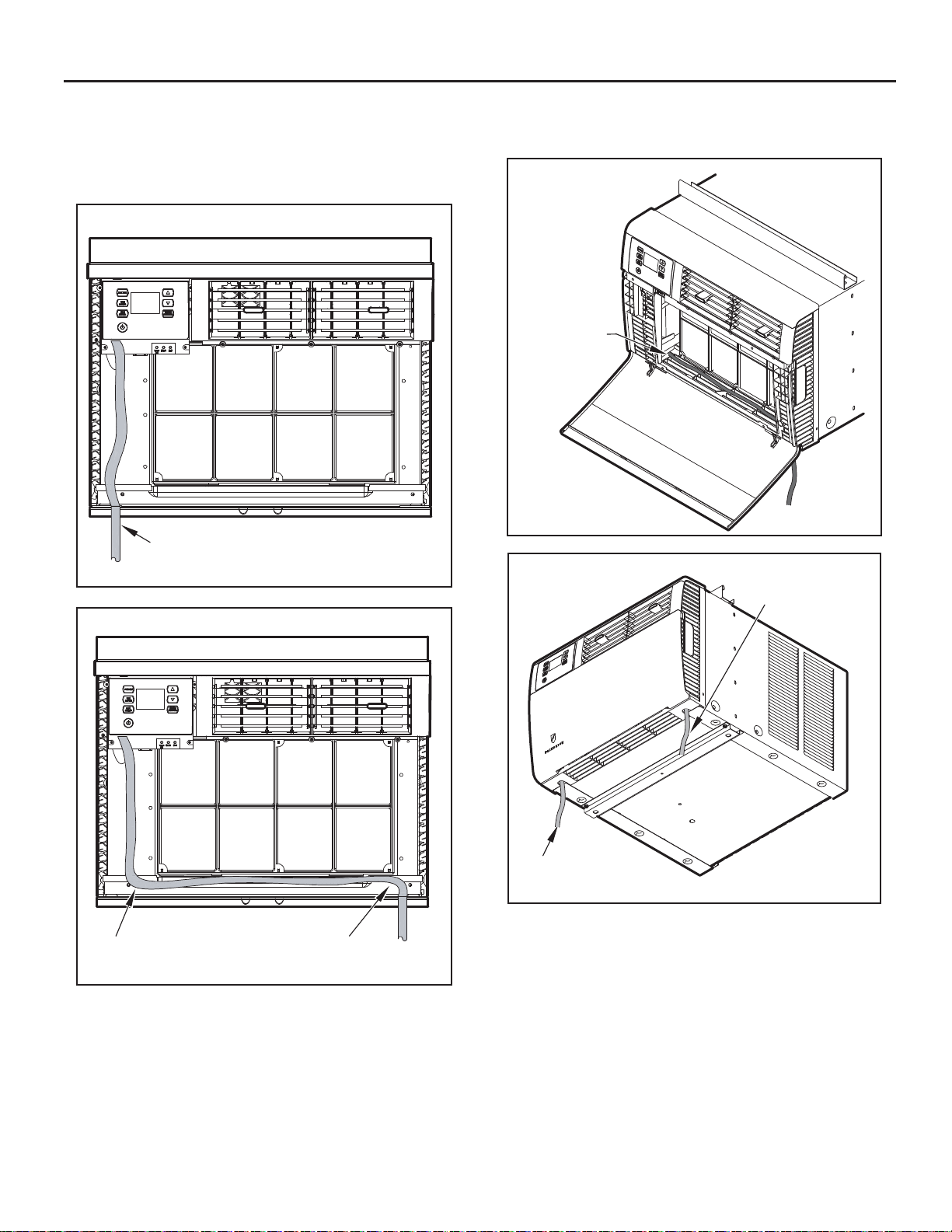
STEP 10. Hold the decorative front as shown in Figure 17 . Insert the two
tabs of the Dec or ati ve Front Panel into t he s lot s in t he to p of
the cabinet and lower the bottom of the decorative front to the
bottom of the cabinet. Route the electrical cord to the right or
left side of the bottom of the cabinet as required by the location
of the electr ical wall outl et. Use the notc hes provid ed at the
bottom of the Decorative Front Panel for routing the electrical
cord out of the unit. Attach the decorative front to the cabinet
with two (2) No. 8 x ½" Phillips head screws (item #2, page 22).
24
ST E P 11. CIRCUIT PROTECTION - If the air conditioner is circuit
protected by a fuse, use a "TIME DELAY" fuse or HACR type
Circuit Breaker due to momentary high current demand when
your air conditioner is started. Before operating your unit, verify
the ampere rating of the time-delay fuse or circuit breaker
which protects your unit. The ampere rating of the time-delay
fuse or circuit breaker shall be 15 amps. Refer to Op eration
section for more detailed operating instructions.
NOTE: Remove tap e and ver if y fi lter is intact, as per fi lter instructions
found inside door.
Page 25
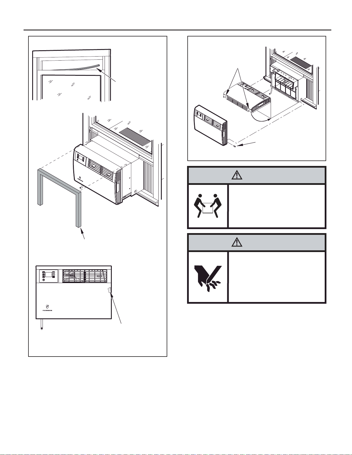
Figure 16
Figure 1 7
NOTCHES PROVIDED FOR
ELECTRICAL CORD EXIT
Front cover removal required
for electrical cord exit.
See Figures 18A and
18B for instruction.
GRAY FOAM
GASKET
(SEE ILLUSTRATION
ITEM #5 ON PAGE 22)
SCREW, #8 x 1/2” PHILLIPS
HEAD (SEE ILLUSTRATION
ITEM #2, PAGE 22)
2 REQUIRED (1 EACH SIDE)
FRR089
CAUTION
Excessive Weight Hazard
Use two or more people when
installing your air conditioner.
CHASSIS SEAL
GASKET
TO PREVENT AIR LEAKS AROUND THE AIR
CONDITIONER, INSERT THE WHITE FOAM
GASKET (ITEM #6, PAGE 22) BETWEEN THE
AIR CONDITIONER AND THE CABINET
FRR088
Failure to do so can result in
back or other injury.
CAUTION
Cut/Sever
Although great care has been
taken to minimize sharp edges
in the construction of your unit,
use gloves or other hand
protection when handling unit
Failure to do so can result in minor
to moderate personal injury.
25
Page 26
Cord Routing Change
Unplug unit.
Your Kühl Q unit will come with the power cord already installed and routed
to the left side of the unit.
For convenience and optimum appearance the direction that the power cord
exits the unit may be changed from le ft to right by following the procedure
below. Select the exit location on the left or right based on proximity to
the power outlet.
STEP 1.
Remove Decorative Front Cover. (See Figures 18A and 18B)
OPEN THE DECORATIVE FRONT COVER
1
WARNING
Electrical Shock Hazard
Make sure your electrical receptacle has the
same configuration as your air conditioner’s
plug. If different, consult a Licensed Electrician.
Do not use plug adapters.
Do not use an extension cord.
Do not remove ground prong.
Always plug into a grounded 3 prong oulet.
Failure to follow these instructions can result in
death, fire, or electrical shock.
LOCATE AND DISCONNECT ELECTRONIC CONTROL POWER CABLE HARNESS.
Figure 18A
2
1
Figure 18B
REMOVE ELECTRONIC CONTROL
2
POWER CABLE HARNESS
26
3
SCREWS ATTACHING DECORACTIVE
FRONT COVER TO UNIT
(4 REQUIRED)
REMOVE 4 SCREWS ATTACHING DECORATIVE
3
FRONT COVER. SAVE TO REINSTALL LATER.
REMOVE DECORATIVE FRONT COVER.
4
STORE IN A SAFE PLACE TO REINSTALL LATER.
(no image)
Page 27
STEP 2. In order to run the p ower cord to the r ight of the unit, route
the cord along bottom inside of the unit (See Figures 20 and
21), under the lower left mounting screw em bo ssm ent s (See
Figure 22) and exit the cord throu gh right side c ord op ening
(See Figure 22) of the decorative front cover. Decorative front
cover will keep cord in place.
Figure 19
FACTORY SETTING WITH LEFT-SIDE
CORD PLACEMENT
FRR201
Figure 20
STEP 3. Reinstall the 4 scr ews remove d earl ier to sec ure De co rative
front cover with cor d exit in g to the front bottom of the unit. (4
screws RETAINED FROM STEP 1)
Figure 21
CLOSE-UP OF
CORD UNDER
LEFT MOUNTING
SCREW
EMBOSSMENT
FRR099
Figure 22
RIGHT-SIDE
CORD ROUTING
NEW CORD ALIGNMENT FOR ROUTING CORD
EXIT TO THE RIGHT OF UNIT
LEFT-SIDE
CORD ROUTING
FRR200
FRR202
27
Page 28
Thru-the-wall Installation
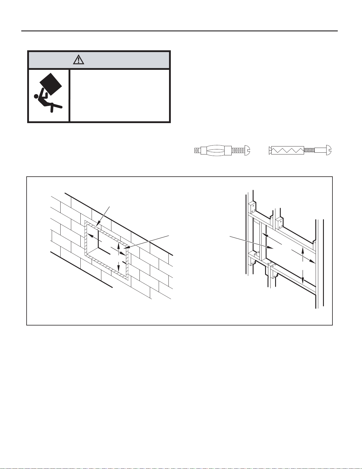
STEP 3. LAYOUT - Cut and frame in an opening in the desired wall area
using the illustration as a guide (See Figure 23).
WARNING
Falling Object Hazard
Not following Installation Instructions
for mounting your air conditioner can
result in property damage, injury, or
death.
STEP 1. After removing the unit from shipping carbon slide chassis out
of cabinet (See Figure 16, page 25).
STEP 2. Remove the shell channel f rom the top of the ca binet (See
Figure 15, page 24).
NOTE: Not applicable to heat pump models sold without quick mounting
cabinet.
Figure 23
2” x 8” FRAME
STEP 4. Place the cabinet in the framed opening.
NOTE: Measure and shim void spaces between the side of cabinet and
STEP 5. Position the front edge to extend into the room 3/4" minimum
STEP 6. Secure each si de of the cabin et with No. 8 x 7/8" hex head
NOTE: Altern ate fasteners which may be used for securing t he unit
MOLLY OR TOGGLE BOLT
wood framing before securing to wall.
at top of cabinet and 1" minimum at bottom (See Figure 24).
screws (item #3, page 22) or nails th rough the holes in t he
sides.
cabinet to a wall, including masonr y walls, are not furnished
(available at local hardware stores).
EXPANSION ANCHOR BOLT
FINISHED OPENING SIZE
20”
14-1/4”
20”
14-1/4”
CONCRETE BLOCK CONSTRUCTION FRAME CONSTRUCTION
FRR091
28
Page 29
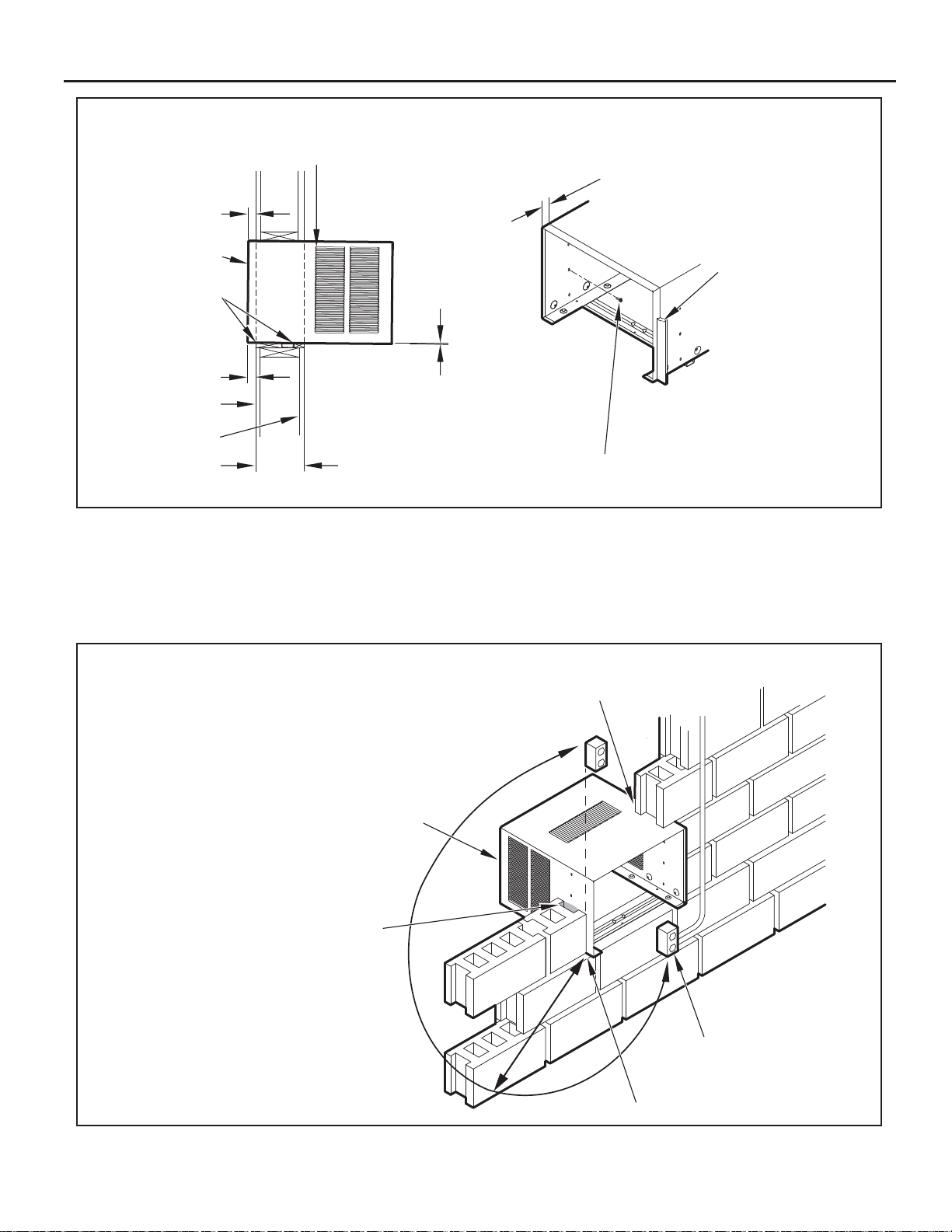
Figure 24
3/4” MINIMUM
CABINET FRONT
1” THICK LUMBER
FRONT EDGE OF LOUVERS
MUST ALWAYS BE OUTSIDE OF
EXTERIOR WALL SURFACE.
3/4” MINIMUM FRONT
EDGE OF CABINET TO
INSIDE WALL SURFACE.
TRIM AROUND THE
CABINET WITH A
SUITABLE WOOD
MOULDING AND
FINISH TO SUIT.
CAULK ALL AROUND
CABINET ON OUTSIDE
TO INSURE A WEATHER
TIGHT SEAL.
1” MINIMUM
INSIDE WALL
EXTERIOR WALL
MAX. WALL
THICKNESS
ALLOWED 8-1/2”
1/4” SLOPE DOWN.
POSITION AND SECURE
CABINET DOWNWARD.
SLOPE OUTSIDE FOR
DRAINAGE.
STEP 7. Cut two pi eces of standard 1" lumber (supplied by installer)
to the length and width requir ed. Place in front and back of
bottom sill channel as shown in Figure 24. Secure wit h nails
(supplied by installer).
STEP 8. Seal all holes in the cabinet with caulking compound (supplied
by installer).
Figure 25
SOLID MASONRY CONSTRUCTION
CABINET
7/8” SLOTTED HEAD SCREWS (3 EA. SIDE)
NAILS MAY BE USED IF DESIRED.
FRR092
STEP 9. Complete the installation by following STEPS 6 through 11 of
Standard Window Installation (Page 24). Window Seal Gasket
mentioned in STEP 9 will not be required.
IMPORTANT: Before operating your unit, read STEP 11 of Standard
Window Instructions.
CAULK ALL SIDES
MORTAR
NOTE: ELECTRICAL RECEPTACLE LOCATION
FROM POINT “X” MUST BE WITHIN A MAXIMUM
RADIUS OF 69” FOR 115V UNITS.
POINT “X”
ELECTRICAL
RECEPTACLE
FRR093
29
Page 30

Final Inspection & Start-up Checklist
Inspect and ensure that all components and accessories have been
installed properly an d that they have not been damage d during the
installation progress.
Check the condensate water drain(s ) to ensure that they are adequate
for the removal of condensate water, and that they meet the approval
of the end user.
Ensure that all installation instructions concerning clearances around
the unit have been adhered to. Check to ensure that the unit air fi lter,
indoor coil, and outdoor coil are free from any obstructions.
Ensure that the circuit breaker(s) or fuse(s) and supply circuit wire
size have been sized correctly . If the unit was supplied with a power
supply cord, insure that it is stored properly.
Ensure that the entire installation is in compliance with all applicable
national and local codes and ordinances having jurisdiction.
Secure components and accessories, such as a decorative front
cover.
Start the unit and c heck for proper op eration of all compo nents in
each mode of operation.
Instruct the owner or operator of the units operat ion, and the
manufacturer's Routine Maintenance.
This is a warm weather appliance
Your air conditioner is designed to cool in warm weather when the outside
temperature is above 60°F (15.6°C) and below 1 1 5 °F ( 46.1° C ) , so it won't
cool a room if it is already cool outside.
Condensation is normal
Air conditioners actually pump the heat and humidity from your room to the
outside. Humidity be com es water, and your air conditioner wi ll use most
of the water to keep the outside c oil c ool. If ther e is excessive humidit y,
there may be excess water that will drip outside. This is normal operation.
Frosting
This usually occurs because of insuffi cient airfl ow across the coils, a dirty
fi lter, cool damp weather, or all of these. Set the SYSTEM mode to FAN
ONLY
will probably prevent the frosting from recurring.
and the frost will disappear . Setting the thermostat a little warmer
Noises
All air conditioners make some noise. Friedr ich units are designed to
operate as quietly as possible. An air conditioner mounted in a wall is quieter
than one mounted in a window. It is impor t ant to ensure t hat the c has sis
seal gasket (Item 14) is properly installed (refer to installation instructions) .
NOTE: A log for rec ording t he dates of maintenanc e and/or ser v ice is
Pr esent the owner or operator of the equipment with the Installation
recommended.
& Operation Manual, all ac c ess ory installation instructio ns, and the
name, address and telephone numbe r of the Authorized Friedric h
Warranty Ser vice Company in the area for future referenc e if
necessary.
30
Page 31

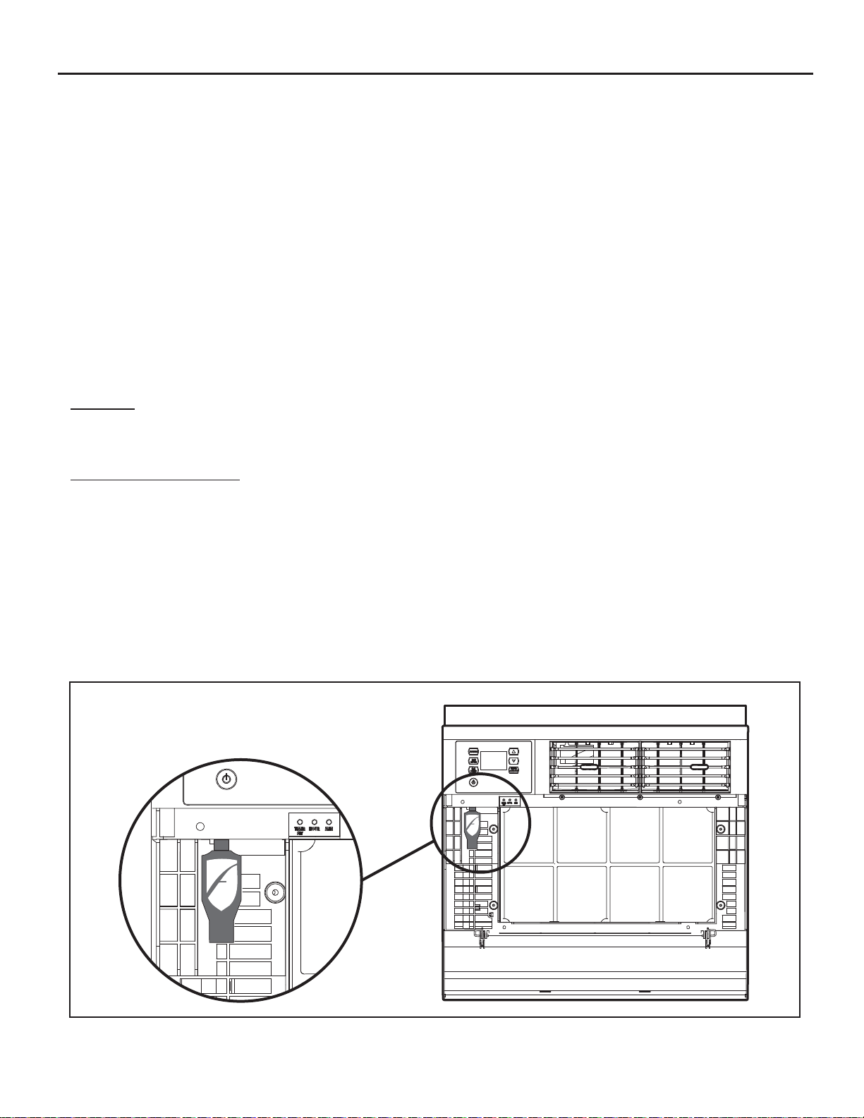
Routine Maintenance
To ensure proper unit operation, the air ¿ lters should be cleaned at least
monthly, and more frequently if conditions warrant. The unit must be turned
off before the ¿ lters are cleaned.
T o Remov e, Wash and Replace F ilter
Lower front panel (See Figure 2). Use handle on ¿ lter to À ex ¿ lter up and
out of retainer. Remove ¿ lter from unit (See Figure 3). Clean ¿ lter monthly
or more frequently if needed. Refer t o accessories section for ¿ lter options.
Coils & Chassis
NOTE: Do not use a caust ic coil c leaning agent on co ils or base pan.
The indoor coil and outdoo r coils and base pan should be inspected
periodically (annually or semi-annually) and cleaned of all debris (lint, dirt,
leaves, paper, etc.) as necessary. Under extreme conditions, more frequent
cleaning m
and compressed air or vac uum. A pressure washer may also be used,
however, you must be careful not to bend the aluminum ¿ n pack. Use a
sweeping up and down motion in the direction of the vertical aluminum ¿ n
pack when pressure cleaning coils.
Use a biodegradable cleaning agent and degreaser. The use
of harsh cleaning materials may lead to deteri oration of the
aluminum ¿ ns or the coil end plates.
ay be required. Clean the coils and base pan with a soft brush
Service and Assistance
Before calling for service, please check the “Troubleshooting Tips” sec-
tion above. This may help you to ¿ nd the answer to your problem, avoid
unnecessary service calls, and save you the cost of a service call if the
problem is not due to the product itself.
You can ¿ nd the name of your local Authorized Service Provider by visiting
our web site at www.friedrich.com.
If you require further assistance
You can call the Customer Support Call Center at 1-800-541-6645.
Before calling, please make sure that you have the complete model and
serial number, and date of purchase of your equipment available. By
providing us with this information, we will be better able to assist you.
Our specialists are able to assist you with:
Speci¿ cations and Features of our equipment.
Referrals to dealers, and distributors.
Use and Care Information.
Recommended maintenance procedures.
Installation information.
Referrals to Authorized Service Providers and Parts depots.
NOTE: It is extremely important to insure that none of the electrical
and/or electroni c par ts of the unit get wet . Be sure to c over all
electrical co
mponents to protect them from water or spray.
Decorative Fr ont
The decorative f ront and disc harge air gr ille may be c leaned w ith a mil d
soap or detergent. Do NOT use solvents or hydrocarbon based cl eaner s
such as acetone, naphtha, gasoline, benzene, etc., to clean the decorative
front or air discharge grilles.
Use a damp (not wet) cloth when cleaning the cont rol area to prevent
water from entering the unit, and possibly damaging the electronic control.
Fan Motor & Compressor
The fan motor & compres sor ar e per manent ly lubr ic ated, and re quire no
additional lubrication.
Wall Sleeve
Inspect the inside of the wall sleeve and drain system periodically (annually
or semi-annually) and clean as required. Under extreme conditions, more
frequent cleaning may be necessar y. Clean both of these areas with an
antibacterial and antifungal cleaner. Rinse both items thoroughly with water
and ensure that the drain outlets are operating correctly. Check the sealant
around the sleeve and reseal areas as needed.
Av ailable Accessories
Carbon Filter Kits
Each kit contains three (3) ¿ lters.
KWCFQ - Carbon ¿ lter kit for "Q" chassis models.
Window Installation Kits
(Standard in Kühl Models without Heat)
KWIKQ
FriedrichLink™ Adapter Accessory:
KWIFI - FriedrichLink™ Adapter Accessory f or wireless control and
additional programming options
Decorative Color Front P anel Kits:
KWBGEQA - Q Model Decorative Front Cover in Classic Beige
KWBLKQA - Q Model Decorative Front Cover in Black Onyx
KWBLUQA - Q Model Decorative Front Cover in Cobalt Blue
KWPNKQA - Q Model Decorative Front Cover in Pink Diamond
KWREDQA - Q Model De
KWWHTQA - Q Model Decorative Front Cover in Designer White
corative Front Cover in Deep Red
See www.friedrich.com for additional accessories for your unit.
31
Page 32

Troubleshooting Tips
COMPLAINT CAUSE SOLUTION
Unit does not operate.
Unit Trips Circuit Breaker or Blows Fuses.
LCDI Power Cord Trips (Reset Button Pops Out).
Unit Does Not Cool/Heat Room Suffi ciently, Or
Cycles On And Off Too Frequently.
Ɣ The unit is turned to the off position,
or the thermostat is satisfi ed.
Ɣ The LCDI power cord is unplugged. Ɣ Plug into a properly grounded 3 prong receptacle.
Ɣ The LCDI power cord has tripped
(Reset button has popped out).
Ɣ The circuit breaker has tripped or
the supply circuit fuse has blown.
Ɣ There has been a local power
failure.
Ɣ Other appliances are being used on
the same circuit.
Ɣ An extension cord is being used. Ɣ Do NOT use an extension cord with this or any
Ɣ The circuit breaker or time-delay
fuse is not of the proper rating.
Ɣ The LCDI power cord can trip (Reset
button pops out) due to disturbances
on your power supply line.
Ɣ Electrical overload, overheating, or
cord pinching can trip (Reset button
pops out) the LCDI power cord.
NOTE: A damaged power supply cord must be replaced with a new power supply cord obtained
from the product manufacturer and must not be repaired.
Ɣ The return/discharge air grille is
blocked.
Ɣ Windows or doors to the outside are
open.
Ɣ The temperature is not set at a cool
enough/warm enough setting.
Ɣ The fi lter is dirty or obstructed. Ɣ Clean the fi lter, (See Routine Maintenance), or
Ɣ The indoor coil or outdoor coil is
dirty or obstructed.
Ɣ There is excessive heat or moisture
(cooking, showers, etc.) in the room.
Ɣ The temperature of the room you
are trying to cool is extremely hot.
Ɣ Turn the unit to the on position and raise or lower
temperature setting (as appropriate) to call for
operation.
See “Electrical Rating Tables” on pg. 6 for the
proper receptacle type for your unit.
Ɣ Press and release RESET (listen for click; Reset
button latches and remains in) to resume operation.
Ɣ Reset the circuit breaker, or replace the fuse as
applicable. If the problem continues, contact a
licensed electrician.
Ɣ The unit will resume normal operation once power
has been restored.
Ɣ The unit requires a dedicated outlet circuit, not
shared with other appliances.
other air conditioner.
Ɣ Replace with a circuit breaker or time-delay fuse
of the proper rating. See “Electrical Rating Tables”
on pg. 6 for the proper circuit breaker/fuse rating
for your unit. If the problem continues, contact a
licensed electrician.
Ɣ Press and release RESET (listen for click; Reset
button latches and remains in) to resume normal
operation.
Ɣ Once the problem has been determined and
corrected, press and release RESET (listen for
click; Reset button latches and remains in) to
resume normal operation.
Ɣ Ensure that the return and/or discharge air paths
are not blocked by curtains, blinds, furniture, etc.
Ɣ Ensure that all windows and doors are closed.
Ɣ Adjust the Temperature control to a cooler or
warmer setting as necessary.
remove obstruction.
Ɣ Clean the coils, (See Routine Maintenance), or
remove obstruction.
Ɣ Be sure to use exhaust vent fans while cooking
or bathing and, if possible, try not to use heat
producing appliances during the hottest part of the
.
day
Ɣ Allow additional time for the air conditioner to cool
off a very hot room.
32
Page 33

COMPLAINT CAUSE SOLUTION
Unit Does Not Cool/Heat Room Suffi ciently, Or
Cycles On And Off Too Frequently (continued).
Unit Runs Too Much.
Ɣ The outside temperature is below
60°F (16° C).
Ɣ The digital control is set to fan
cycling mode.
Ɣ The air conditioner has insuffi cient
cooling capacity to match the heat
gain of the room.
Ɣ The air conditioner has insuffi cient
heating capacity to match the heat
loss of the room.
Ɣ This may be due to an excessive
heat load in the room.
Ɣ It may also be due to an improperly
sized unit.
Ɣ This may be normal for higher
effi ciency (EER) air conditioners.
Ɣ You may notice that the discharge
air temperature of your new air
conditioner may not seem as cold
as you may be accustomed to from
older units. This does not, however,
indicate a reduction in the cooling
capacity of the unit.
Ɣ Do not try to operate your air conditioner in the
cooling mode when the outside temperature is
below 60°F (16° C). The unit will not cool properly,
and the unit may be damaged.
Ɣ Since the fan does not circulate the room air
continuously at this setting, the room air does not
mix as well and hot (or cold) spots may result.
Using the continuous fan setting is recommended
to obtain optimum comfort levels.
Ɣ Check the cooling capacity of your unit to ensure it
is properly sized for the room in which it is installed.
Room air conditioners are not designed to cool
multiple rooms.
Ɣ Check the heating capacity of your unit. Air
conditioners are sized to meet the cooling load,
and heater size is then selected to meet the
heating load. In extreme northern climates, room
air conditioners may not be able to be used as a
primary source of heat.
Ɣ If there are heat producing appliances in use in the
room, or if the room is heavily occupied, the unit will
need to run longer to remove the additional heat.
Ɣ Be sure to use exhaust vent fans while cooking
or bathing and, if possible, try not to use heat
producing appliances during the hottest part of the
day.
Ɣ The use of higher effi ciency components in your
new air conditioner may result in the unit running
longer than you feel it should. This may be more
apparent, if it replaced an older, less effi cient,
model. The actual energy usage, however, will be
signifi cantly less when compared to older models.
Ɣ The energy effi ciency ratio (EER) and cooling
capacity rating (Btu/h) listed on the unit’s rating
plate are both agency certifi ed.
33
Page 34

Addendum 1
Schedule T able with Energy Saving Values
Period Sun Mon Tues Wed Thur Fri Sat
Start Time 600 Start Time 600 Start Time 600 Start Time 600 Start Time 600 Start Time 600 Start Time 600
System Mode Cool System Mode Cool System Mode Cool System Mode Cool System Mode Cool System Mode Cool System Mode Cool
Fan Mode Auto Fan Mode Auto Fan Mode Auto Fan Mode Auto Fan Mode Auto Fan Mode Auto Fan Mode Auto
1
Fan Speed Low Fan Speed Low Fan Speed Low Fan Speed Low Fan Speed Low Fan Speed Low Fan Speed Low
Set Point Cool 78 Set Point Cool 78 Set Point Cool 78 Set Point Cool 78 Set Point Cool 78 Set Point Cool 78 Set Point Cool 78
Set Point Heat 70 Set Point Heat 70 Set Point Heat 70 Set Point Heat 70 Set Point Heat 70 Set Point Heat 70 Set Point Heat 70
Start Time 800 Start Time 800 Start Time 800 Start Time 800 Start Time 800 Start Time 800 Start Time 800
System Mode Cool System Mode Cool System Mode Cool System Mode Cool System Mode Cool System Mode Cool System Mode Cool
Fan Mode Auto Fan Mode Auto Fan Mode Auto Fan Mode Auto Fan Mode Auto Fan Mode Auto Fan Mode Auto
2
Fan Speed Low Fan Speed Low Fan Speed Low Fan Speed Low Fan Speed Low Fan Speed Low Fan Speed Low
Set Point Cool 85 Set Point Cool 85 Set Point Cool 85 Set Point Cool 85 Set Point Cool 85 Set Point Cool 85 Set Point Cool 85
Set Point Heat 62 Set Point Heat 62 Set Point Heat 62 Set Point Heat 62 Set Point Heat 62 Set Point Heat 62 Set Point Heat 62
Start Time 1800 Start Time 1800 Start Time 1800 Start Time 1800 Start Time 1800 Start Time 1800 Start Time 1800
System Mode Cool System Mode Cool System Mode Cool System Mode Cool System Mode Cool System Mode Cool System Mode Cool
Fan Mode Auto Fan Mode Auto Fan Mode Auto Fan Mode Auto Fan Mode Auto Fan Mode Auto Fan Mode Auto
3
Fan Speed Low Fan Speed Low Fan Speed Low Fan Speed Low Fan Speed Low Fan Speed Low Fan Speed Low
Set Point Cool 78 Set Point Cool 78 Set Point Cool 78 Set Point Cool 78 Set Point Cool 78 Set Point Cool 78 Set Point Cool 78
Set Point Heat 70 Set Point Heat 70 Set Point Heat 70 Set Point Heat 70 Set Point Heat 70 Set Point Heat 70 Set Point Heat 70
Start Time 2200 Start Time 2200 Start Time 2200 Start Time 2200 Start Time 2200 Start Time 2200 Start Time 2200
System Mode Cool System Mode Cool System Mode Cool System Mode Cool System Mode Cool System Mode Cool System Mode Cool
Fan Mode Auto Fan Mode Auto Fan Mode Auto Fan Mode Auto Fan Mode Auto Fan Mode Auto Fan Mode Auto
4
Fan Speed Low Fan Speed Low Fan Speed Low Fan Speed Low Fan Speed Low Fan Speed Low Fan Speed Low
Set Point Cool 82 Set Point Cool 82 Set Point Cool 82 Set Point Cool 82 Set Point Cool 82 Set Point Cool 82 Set Point Cool 82
Set Point Heat 62 Set Point Heat 62 Set Point Heat 62 Set Point Heat 62 Set Point Heat 62 Set Point Heat 62 Set Point Heat 62
Commercial Schedule
Period Sun Mon Tues Wed Thur Fri Sat
Start Time 700 Start Time 700 Start Time 700 Start Time 700 Start Time 700 Start Time 700 Start Time 700
System Mode Cool System Mode Cool System Mode Cool System Mode Cool System Mode Cool System Mode Cool System Mode Cool
Fan Mode Auto Fan Mode Auto Fan Mode Auto Fan Mode Auto Fan Mode Auto Fan Mode Auto Fan Mode Auto
1
Fan Speed Med Fan Speed Med Fan Speed Med Fan Speed Med Fan Speed Med Fan Speed Med Fan Speed Med
Set Point Cool 84 Set Point Cool 75 Set Point Cool 75 Set Point Cool 75 Set Point Cool 75 Set Point Cool 75 Set Point Cool 84
Set Point Heat 62 Set Point Heat 70 Set Point Heat 70 Set Point Heat 70 Set Point Heat 70 Set Point Heat 70 Set Point Heat 62
Start Time 1800 Start Time 1800 Start Time 1800 Start Time 1800 Start Time 1800 Start Time 1800 Start Time 1800
System Mode Cool System Mode Cool System Mode Cool System Mode Cool System Mode Cool System Mode Cool System Mode Cool
Fan Mode Auto Fan Mode Auto Fan Mode Auto Fan Mode Auto Fan Mode Auto Fan Mode Auto Fan Mode Auto
2
Fan Speed Med Fan Speed Med Fan Speed Med Fan Speed Med Fan Speed Med Fan Speed Med Fan Speed Med
Set Point Cool 84 Set Point Cool 84 Set Point Cool 84 Set Point Cool 84 Set Point Cool 84 Set Point Cool 84 Set Point Cool 84
Set Point Heat 62 Set Point Heat 62 Set Point Heat 62 Set Point Heat 62 Set Point Heat 62 Set Point Heat 62 Set Point Heat 62
Residenal Schedule
34
Page 35

Friedrich Air Conditioning Company
10001 Reunion Place, Suite 500
San Antonio, TX 78216
800.541.6645
www.friedrich.com
ROOM AIR CONDITIONERS
LIMITED WARRANTY
FIRST YEAR
ANY PART: If any part supplied by FRIEDRICH fails because of a defect in workmanship or material within twelve months from
date of original purchase, FRIEDRICH will repair the product at no charge, provided room air conditioner is reasonably accessib le
for service. Any additional labor cost for removing inaccessible units and/or charges for mileage related to travel by a Service
Agency that exceeds 25 miles one way will be the responsibility of the owner. This remedy is expressly agreed to be the exclusive
remedy within twelve months from the date of the original purchase.
SECOND THROUGH FIFTH YEAR
SEALED REFRIGERANT SYSTEM: If the Sealed Refrigeration System (defined for this purpose as the compressor, condenser
coil, evaporator coil, reversing valve, check valve, capillary, filter drier, and all interconnecting tubing) supplied by FRIEDRICH in
your Room Air Conditioner fails because of a defect in workmanship or material within sixty months from date of
FRIEDRICH will pay a labor allowance and parts necessary to repair the Sealed Refrigeration System; PROVIDED FRIEDRICH will
not pay the cost of diagnosis of the problem, removal, freight charges, and transportation of the air conditioner to and from the
Service Agency, and the reinstallation charges associated with repair of the Sealed Refrigeration System. All such cost will be the
sole responsibility of the owner. This remedy is expressly agreed to be the exclusive remedy within sixty months from the date of the
original purchase.
APPLICABILITY AND LIMITATIONS: This warranty is applicable only to units retained within the Fifty States of the U.S.A., District
of Columbia, and Canada. This warranty is not applicable to:
purchase,
1. Air filters, fuses, batteries and the front grille removal tool.
2. Products on which the model and serial numbers have been removed.
3. Products which have defects or damage which results from improper installation, wiring, electrical current
OBTAINING WARRANTY PERFORMANCE: Service will be provided by the FRIEDRICH Authorized Dealer or Service
Organization in your area. They are listed in the Yellow Pages. If assistance is required in obtaining warranty performance, write
to: Room Air Conditioner Service Manager, Friedrich Air Conditioning Co., 10001 Reunion Place, Ste.500, San Antonio, TX., 78216.
LIMITATIONS: THIS WARRANTY IS GIVEN IN LIEU OF ALL OTHER WARRANTIES. Anything in the warranty
notwithstanding, ANY IMPLIED WARRANTIES OF FITNESS FOR PARTICULAR PURPOSE AND/OR MERCHANTABILITY
SHALL BE LIMITED TO THE DURATION OF THIS EXPRESS WARRANTY. MANUFACTURER EXPRESSLY DISCLAIMS AND
EXCLUDES ANY LIABILITY FOR CONSEQUENTIAL OR INCIDENTAL DAMAGE FOR BREACH OF ANY
IMPLIED WARRANTY.
Performance of Friedrich’s Warranty obligation is limited to one of the following methods:
1. Repair of the unit
2. A refund to the customer for the prorated value of the unit based upon the remaining warranty period of the unit.
The method of fulfillment of the warranty obligation is at the sole discretion of Friedrich Air Conditioning.
NOTE: Some states do not allow limitations on how long an implied warranty lasts, or do not allow the limitation or exclusion of
consequential or incidental damages, so the foregoing exclusions and limitations may not apply to you.
OTHER: This warranty gives you specific legal rights, and you may also have other rights which vary from state to state.
PROOF OF PURCHASE: Owner must provide proof of purchase in order to receive any warranty related services.
All service calls for explaining the operation of this product will be the sole responsibility of the consumer.
All warranty service must be provided by an Authorized FRIEDRICH Service Agency, unless authorized by FRIEDRICH prior to
repairs being made.
characteristics, or maintenanc
of the product and/or units installed in a corrosive atmosphere, default or delay in performance caused by war,
government restrictions or restraints, strikes, material shortages beyond the control of FRIEDRICH, or acts of God.
3. Providing a replacement unit of equal value
e; or caused by accident, misuse or abuse, fire, flood, alterations and/or misapplication
EXPRESSED OR
35
Page 36

Friedrich Air Conditioning Co.
10001 Reunion Place, Suite 50San Antonio, Texas 78216
1-800-541-66450
www.friedrich.com
Printed in Mexico
93001003_01
Page 37

Unidades de Aire Acondicionado
AUTO
F
C
AUTO FAN
AM
CONTINUOUS
PM
88
ONOFF
SET POINT
SCHEDULE
ROOM TEMP
CHECK $MART
AUTO SPEED
FILTER
SYSTEM
FAN MODE
POWER
FAN SPEED
SCHEDULE
Modelos Q Chassis
Manual de Instalación y Funcionamiento
Kühl
Kühl +
Frío & Calor Eléctrico
93001003_01
115-Voltios: SQ05, SQ06, SQ08, SQ10
115-Voltios: EQ08
Page 38

Gracias por su decisión de comprar el Aire Acondicionado de Alta Eficiencia Friedrich. Su nuevo Friedrich ha sido cuidadosamente diseñado y
fabricado para darle muchos años de funcionamiento confiable y eficiente, manteniendo una temperatura y nivel de humedad confortables. Se
han incorporado muchas características adicionales a la unidad para garantizar un funcionamiento silencioso, la mayor circulación de aire frío y
seco, y el funcionamiento más económico.
GRACIAS, a nombre de toda nuestra empresa,
por hacer una compra tan inteligente.
Registre su aíre acondicionado
La información del modelo se puede encontrar en la
placa de identificación detrás de la tapa frontal.
Favor de llenar y enviar la tarjeta de registro
proporcionada con este producto, o registrarse en
línea en www.friedrich.com. Para su futura
comodidad, registre la información del modelo aquí.
NÚMERO DE MODELO
NÚM
ERO
DE SERIE
FRIEDRICH
AIR CONDITIONING CO.
SAN ANTONIO, TX
MODEL NUMBER
EQ08N11-A
SERIAL NUMBER
AALY00219
VOLTS
115
103 VOLT MIN.
COOLING:
BTU/HR
7500
EER
9.8
AMPS
6.9
HEATING:
BTU/HR
4000
EER
AMPS
11.2
MAX AMPS:
23.5 OZS.
DESIGN PRESSURES
U.S. PATENTS
IF CONNECTED TO
A FUSE PROTECTED
CIRCUIT, USE A 12 A
TIME DELAY FUSE
ROOM AIR
CONDITIONER
60 HZ/ 1PH
600 PSIG HS
300 PSIG LS
D458, 229 S
5,634,346
LISTED 183H
FRIEDRICH
AIR CONDITIONING CO.
SAN ANTONIO, TX
Assembled in Mexico
MODEL NUMBER
EQ08N11-A
SERIAL NUMBER
AALY00219
VOLTS
60 HZ/ 1PH
FECHA DE COMPRA
2
Page 39

Índice
Índic e .. ...... ...... ..... ...... ...... ........ ....... ...... ...... ...... ..... ........ ...... ...... ..... ........ ........ ...... .... ..... ........ ...... ..... ........ ...... ...... ....... ...... ...... ...... ..... .......... ...... ...... ..... ...... 3
Medidas de Seguridad ................................................................................................................... ..... ...... ........ ..... ........ .... ...... ...... ..... ...... ........ ........ ..... .... 4
Instrucciones de Desempacado ........................................................................................................................................................................................ 5
ADVERTENCIA: Antes de Operar su Unidad .................................................................................................................................................................. 6
Limpieza del Filtro Estándar / Instrucciones de Instalación ....................................................................... ...... ..... ...... ........ ........ ..... ...... ...... ...... ...... ....... 7
Instrucciones de Instalación del Filtro de Carbono Premium .................................................................................................................
Funcionamiento del Panel de Control ........................................................................................................... ...... ....... ...... ........ ..... ...... ...... ...... ...... ......... .. 8
Nuevas Opciones del Control Kühl .................................................................... ....... ...... ...... ...... ....... ...... ...... ...... ....... ...... ........ ...... ... ...... ...... ...... ....... ...... 9
Instrucciones de Funcionamiento del Panel de Control ....................................................................................... . .. .. .. .. .. .... .. .... .. .. .. . .. .. .. .. .. .. .. .... .. .. .. . .. .. 1 0
Funcionamiento del Control Remoto ............................................................................................................................................................
Efectividad del Control Remoto .......................................................................................................... .. .... .. .. .. .. .... .. . .. .. .... .. .. .. .. .. .. .. . .. .. .. .... .. .. .. .. .. .... . .. .. .. 1 9
Selección y Ajuste del Flujo de Aire ...................................................................................................... .. .. .. .. .. .. .... ... .. .. .. .. .. .. .. .. .. ................... .. .. .. .. ... .... .. 21
Instrucciones de Instalación ............................................................................................................................................................................................ 21
Artículos Requeridos Para la Instalación (proporcionados en las unidades de enfriamiento directo únicamente) ................................................. 22
Instalación de Ventana Estándar ................................................................................................................... .. .. .... . .... .. .. .. .. .. .. .. .. .. .. . .... .. .. .. .. .. .. .. .. .. ..... .. .. 23
Cambio de Enrutamiento del Cable ................................................................................................................................................................................
Instalación a Través de la Pared .................................................................................................................................................................................... 28
Inspección Fin
Mantenimiento de Rutina ............................................................................................................................................................................................... .. 3 1
Servicio y Asistencia ......................................................................................................................................................................
Accesorios Disponibles............................................................................................................................................................ .. .. .. .. . .... .. .. .. .. .. .. .... .. .. ... .. .. 31
Consejos Para Solucionar Problemas ............................................................................................................................
Anexo 1 ............................................................................................................................................................................................................................. 34
al & Lista de Verificación de Arranque ................................................................................................................................................
............ ..... ...... 7
.................. 19
26
... 30
.................................. 31
................................................ 32
3
Page 40

Ó
Medidas de Seguridad
Su seguridad y la seguridad de los demás son muy importantes.
Hemos proporcionado muchos mensajes de seguridad importantes en este manual y en su electrodoméstico. Siempre lea y obedezca
todos los mensajes de seguridad.
Este es un símbolo de alerta de seguridad.
Este símbolo le advierte de los peligros potenciales que pueden matar o lastimar a usted y a los demás.
Todos los mensajes de seguridad le seguirán al símbolo de alerta de seguridad con la palabra "ADVERTENCIA" o
"PRECAUCIÓN". Estas palabras significan:
ADVERTENCIA
PRECAUCI
Todos los mensajes de seguridad le dirán cuál es el peligro potencial, le dirán cómo reducir el riesgo de lesiones, y le dirán lo que
sucederá si no se siguen las instrucciones.
AVISO
Indica un peligro que, de no evitarse, puede resultar en lesiones personales graves o en la
muerte y en daños al producto u otros bienes.
Indica un peligro que, de no evitarse, puede resultar en lesiones personales y en daños al
N
producto u otros bienes.
Indica que le pueden ocurrir daños a los bienes si no se siguen las instrucciones.
ADVERTENCIA
Sistema de enfriamiento
bajo alta presión
No perforar, calentar, exponer a las llamas o incinerar.
Únicamente los técnicos certificados en refrigeración
deben reparar este equipo.
Los sistemas R410A funcionan a presiones más altas que
el equipo R22. Se deben utilizar prácticas adecuadas de
servicio y manejo seguro.
Únicamente utilice los medidores de presión diseñados
para su uso con R410A. No utilice los medidores de
presión estándar R22.
4
Page 41

Instrucciones de Desempaquetado
PASO 1 CORTAR TODAS CINTAS DEL EMPAQUETADO.
PASO 2 CORTAR LA CINTA ADHESIVA Y ABRIR.
PASO 3 SACAR EL MATERIAL DEL EMPAQUETADO Y LAS CORTINAS
LATERALES DE CARTÓN.
PASO 4 SACAR LENTAMENTE LA CAJA EXTERIOR.
PASO 5 SACAR LOS POSTES ESQUINEROS.
PASO 6 SACAR LA UNIDAD DE LA BANDEJA DE TRANSPORTE.
PASO 7 SACAR EL FILTRO DE CARBONO Y EL EQUIPO DE
FERRETERÍA DE LA BANDEJA INFERIOR.
PASO 2
PASO 1
CORREAS X3
PASO 4
PASO 3
PASO 6
PASO 7
PASO 5
5
Page 42

ADVERTENCIA: Antes de Operar Su Unidad
:
Asegúrese de que el cableado sea adecuado para su unidad.
Si tiene fusibles, deben ser del tipo de retardo. Antes de instalar o trasladar
esta unidad, asegúrese de que el amperaje del interruptor o el fusible de
retardo no superen el amperaje en el Cuadro 1.
NO utilice un cable de extensión.
El cable proporcionado le suministrará la cantidad de energía eléctrica
adecuada a la unidad; puede que un cable de extensión no.
Asegúrese de que la toma de corriente sea compatible
con el enchufe del aire acondicionado proporcionado.
Esto garantiza una conexión a tierra adecuada. Si usted tiene una toma de
corriente de dos clavijas, tendrá que solicitar que un electricista certificado
se lo sustituya por una toma de corriente conectada a tierra. La toma de
corriente conectada a tierra debe cumplir con todos los códigos y
reglamentos locales y nacionales. Bajo ninguna circunstancia se deberá
ar la clavija de tierra del enchufe. Debe utilizar el enchufe de tres
quit
clavijas suministrado con el aire acondicionado.
Pruebe el cable de alimentación
Todas las unidades de aire acondicionado Friedrich salen de fábrica con un
cable de alimentación equipado con un Interruptor de Detección de Fugas
de Corriente (LCDI, en inglés). El dispositivo LCDI cumple con los
requisitos de UL y NEC para aires acondicionados conectados mediante
cable a partir de agosto de 2004.
Para probar el
cable de alimentación:
1. Enchufar el cable de alimentación a una toma de corriente
de 3 clavijas con conexión a tierra.
2. Oprimir el botón RESET (Ver Diagrama 1).
3. Oprimir el botón TEST, escuchar el chasquido; el botón
RESET se detona y se bota.
4. Oprimir y soltar el botón RESET (Escuchar el chasquido; el
botón RESET se traba y permanece adentro). El cable de
alimentación está listo para su uso.
Una vez conectada, la unidad funcionará con normalidad sin necesidad
reiniciar el dispositivo LCDI.
Si el dispositivo LCDI no se detona al ponerse a prueba o si el cable de
alimentación está dañado, debe ser sustituido por un nuevo cable de
alimentación del fabricante. Póngase en contacto con nuestra Línea de
Asistencia Técnica al (800) 541-6645.
Para agilizar el servicio, por favor tenga su número de modelo a la mano.
AVISO
No utilizar el dispositivo LCDI como un interruptor de
ENCENDIDO/APAGADO.
El incumplimiento de est
que el equipo falle de forma prematura.
de
a precaución puede ocasionar
Cuadro 1.
MODELO
XQ05 -
XQ06
XQ08 -
XQ10
XQ08
Diagrama 1
CAPACIDAD DEL
CIRCUITO O FUSIBLE DE
RETARDO
TOMA DE CORRIENTE
REQUERIDA
AMP VOLT NO. NEMA
15 125 5 – 15 P
ADVERTENCIA
Peligro de Descarga Eléctrica
Asegurarse de que su toma de corriente eléctrica tenga
la misma configuración que el enchufe de su aire
acondicionado. Si es diferente, consultar a un
Electricista Certificado.
No utilizar adaptadores de enchufe.
No utilizar un cable de extensión.
No quitar la clavija de tierra.
Conectar siempre a una toma de corriente de 3 clavijas
con conexión a tierra.
El incumplimiento de estas instrucciones puede
ocasionar la mue
eléctrica.
¡PROBAR ANTES DE CADA USO!
1. OPRIMIR EL BOTÓN
2. ENCHUFAR EL LCDI A LA
3. OPRIMIR EL BOTÓN TEST,
4. PRESIONAR EL BOTÓN
NO UTILIZAR SI LA PRUEBA
ANTERIOR FALL A.
CUANDO LA LUZ VERDE ESTÁ
ENCENDIDA, ¡FUNCIONA
CORRECTAMENTE!
rte, un incendio o una descarga
RESET
TEST
ADVERTENCIA
RESET.
TOMA DE CORR IENTE.
EL BOTÓN RESET SE DEBE
BOTAR.
RESET PARA UTILIZAR.
FRR072
6
Page 43

Limpieza del Filtro Estándar / Instrucciones de Instalación
PASO 1. Jalar para abrir la puerta y quitar el filtro sujetando el mango del
filtro y empujando el soporte del filtro hacia arriba y hacia afuera.
Diagrama 2
PUERTA
DEL FILTRO
FRR075
PASO 2. Limpiar el marco frontal, lavando la suciedad del filtro. Usar una
solución de jabón suave si es necesario. Permitir que el filtro se
seque.
PASO 3. Instalar el filtro de vuelta en la unidad. Seguir las instrucciones en
el interior de
la puerta delantera.
Diagrama 3
INSTRUCCIONES
DEL MARCO DEL
FILTRO
PUERTA
DEL FILTRO
FRR076
Instrucciones de Instalación del Filtro de Carbono Premium
Por favor, siga las siguientes instrucciones para instalar el filtro de carbono
Friedrich. El filtro de carbono debe ser reemplazado después de 300 horas
de funcionamiento, 3 meses, o con mayor frecuencia si es necesario para
la eficacia máxima.
Cuando reemplace el filtro de carbono, limpiar el filtro de malla lavable si
está sucio. Permita que el filtro de malla se seque antes de reinsertar.
1. Quitar el marco del filtro de plástico negro de la unidad siguiendo
PASO
las instrucciones en el interior de la puerta del filtro. (El filtro de
malla lavable viene incluido y se sujeta de manera permanente
al marco del filtro).
PASO 2. Colocar el marco del filtro de plástico negro sobre una superficie
plana, con los 6 ganchos del marco del filtro hacia arriba.
Diagrama 4
GANCHOS DEL
MARCO DEL
FILTRO (6)
FRR077
PASO 3. Colocar de vuelta el marco del filtro de plástico negro con el filtro
¡El filtro de carbono ya está listo para su uso!
Colocar el filtro de carbono sobre el marco del filtro de manera
6 de agujeros de instalación del filtro de carbono estén
que los
alineados con los 6 ganchos del marco del filtro. (Diagrama 4)
Afianzar el filtro de carbono al marco del filtro. Asegurarse de
que todos los 6 ganchos del marco del filtro se inserten a través
de los 6 agujeros de instalación del filtro de carbono. Los
ganchos de instalación sostendrán el filtro de forma segura.
de carbono instalado (Diag
rama 5) en la parte frontal de la
unidad, siguiendo las instrucciones en el interior de la puerta del
filtro.
Diagrama 5
FRR078
7
Page 44

Funcionamiento del Panel de Control
j
/
Veamos cómo controlar su aire acondicionado. En el panel de control, justo por encima del botón POWER, hay una pantalla de cristal líquido (LCD, en inglés).
Todos los botones de función del panel de control y los íconos modo se pueden ver en el Diagrama 6.
Encendido – Oprimir el botón para encender el aire acondicionado. El botón de encendido se ilumina para indicar que la unidad está encendida. La luz de fondo
en el interruptor de encendido se atenuará automáticamente al 20% de intensidad después de 15 segundos de inactividad. El control remoto también se puede
utilizar para poner en ENCENDIDO / APAGADO (Ver control remoto).
Pantalla – La pantalla es un LCD de alta eficiencia con una luz de fondo blanca integrada. La luz de fondo tiene una función automática de difuminación de dos
(2) etapas. Después de 15 segundos de inactividad, la pantalla se difumina al 20% de intensidad. Después de un perí
se apaga. Al tocar cualquier botón la pantalla cambia automáticamente a su brillo máximo.
Hay tres botones pulsadores de control en cada lado de la pantalla.
Diagrama 6
FRÍO
SÓLO
VENTILADOR CALOR
BLOQUEO DE
CONTROL
MANTENIMIENTO
REQUERIDO
SISTEMA:
Ciclos entre
CALOR, FRÍO o
SOLO VENTILADOR
MODO DE VENTILADOR :
Deja el ventilador
ya sea en:
- Ciclo de forma automática
ecutar de forma continua
E
VELOCIDAD DEL VENTILADOR:
Pone la velocidad
del ventilador:
BAJA, MED, ALTA o AUTO
(según venga equipado)
F
AUTO FAN
CONTINUOUS
SET POINT
ROOM TEMP
AUTO SPEED
CHECK $MART
FILTER
C
AM
PM
ON OFF
SCHEDULE
ENCENDIDO / APAGADO:
Pone la unidad en
encendido / apagado
VELOCIDAD DEL VENTILADOR
Velocidad del ventilador
seleccionada
VELOCIDAD EN AUTOMÁTICO
Selecciona automáticamente la mejor
velocidad de enfriamiento del ventilador
FILTRO
Revisar / Limpiar
FUNCIONAMIENTO INTELIGENTE $
(si viene equipado)
odo adicional de 120 segundos, la pantalla
WI-FI ENCENDIDO
(si viene equipado)
TEMPERATURA:
Incremento ARRIBA
ESPERA
TEMPERATURA:
Incremento ABAJO
PROGRAMACIÓN
ENCENDIDA
TEMPORIZADOR
PROGRAMACIÓN
Se pone en ENCENDIDO
o APAGADO
RELOJ ENCENDIDO
VENTANA IR:
No bloquearla
PANTALLA DE 2 DÍGITOS
Muestra Configuración para:
- Punto Establecido (Temperatura)
- Temperatura Ambiente
- Reloj (AM / PM)
FRR079
8
Page 45

Nuevas Opciones de Control Kühl
El nuevo Kühl le ofrece una gran variedad de opciones para el control, la
programación y temporización, incluyendo capacidades inalámbricas. El
nuevo Adaptador FriedrichLink™ (se vende por separado) le permite
convenientemente controlar, programar y supervisar su unidad de aire
acondicionado de forma remota desde un teléfono inteligente o
computadora. (El accesorio del Adaptador FriedrichLink™ está disponible a
través de minoristas Friedrich
sección del Adaptador FriedrichLink™ en www.friedrich.com para obtener
más detalles)
Opciones de Programación Pre Programadas:
El control digital de su unidad viene equipado con un temporizador de 24
horas y dos opciones pre programadas de manejo de energía por 7 días.
Temporizador de 24 Horas
El temporizador de 24 horas le permite apagar y encender la unidad en
horarios predeterminados mediante el establecimiento de un horario de
encendido y apagado en el panel de control de la unidad. (Vea la página 11
para obtener detalles sobre la configuración del temporizador.)
Manejo de la Energía Pre Programada
Su unidad viene de fábrica con dos (2) ajustes de Manejo de Energía Pre
Programados como se muestra en el Anexo 1 (Cuadro de Programación
Residencial y Comercial).
Las Opciones de Programación del Manejo de Energía son:
1. Programación Residencial – Semana Laboral de 40 Horas
2. Programación Comercial – Semana Laboral de 5 Días
La Programación "Residencial" (Semana Laboral de 40 Horas) tiene cuatro
(4) períodos de tiempo: 06:00, 08:00, 18:00 y 22:00. Esta op
su unidad Kühl Q eleve temporalmente la temperatura ambiente a 85°F
durante las horas en las que la mayoría de la gente está en el trabajo,
bajándola de nuevo a 78°F antes de que la mayoría de la gente volverá a
casa, y luego elevándola ligeramente a 82°F para mantener una
temperatura cómoda durante la noche.
La Programación "Comercial" (Semana Laboral de 5 Días) tiene dos (2)
períodos de tiempo: 07:00 y 18:00. Esta opción hará que su unidad Kühl Q
temperatura a 84°F después de las horas de trabajo habituales y
eleve la
en fines de semana cuando los espacios comerciales suelen estar
desocupados.
(Vea la Sección de Instrucciones de Funcionamiento del Panel de Control)
Diagrama 7
autorizados o www.friedrich.com. Vea la
ción hará que
Opciones de Programación Personalizada:
La programación personalizada, con un máximo de cuatro ajustes de
temperatura por día, se pueden subir a la unidad a través de la interface de
la micro USB del aire acondicionado o transmitirse convenientemente de
forma inalámbrica mediante el accesorio del NUEVO Adaptador
FriedrichLink™, lo que simplifica enormemente la programación de una o
varias unidades.
Opciones de Programación Personalizada:
1. RECOMENDADO: Programar y controlar de forma inalámbrica
su unidad Kühl a través de una computadora o dispositivo
telefónico inteligente mediante el sistema FriedrichLink™. Se
requiere un adaptador FriedrichLink™ por unidad Kühl, así
como el acceso inalámbrico a Internet.
iene que insertar el Adaptador FriedrichLink™ al puerto de
Sólo t
la micro USB de la unidad como se muestra en el Diagrama 7.
2. Utilizar el Adaptador FriedrichLink™ como una unidad flash para
cargar una programación personalizada a su unidad Kühl.
Conectar el Adaptador FriedrichLink™ a su PC para crear una
programación personalizada (La aplicación de Termostato
Personalizado viene pre cargada en el accesorio del Adaptador
FriedrichLink™). Una vez que se cree la programación
personaliz
conectarlo en la unidad Kühl para cargar. Se pueden cargar
múltiples unidades con el mismo Adaptador FriedrichLink™.
3. Descargar la Aplicación de Programación Personalizada de
www.friedrich.com y cargar a su unidad Kühl con una
computadora portátil y USB al cable de la micro USB. (Cable no
incluido).
Para obtener instrucciones detalladas de instalación de la
Aplicación de Programación, consultar la página FriedrichLink™
bajo la sección de "Soporte & Descargas" en www.friedrich.com.
ada, retirar el Adaptador FriedrichLink™ de la PC y
FRR203
9
Page 46

Instrucciones de Funcionamiento del Panel de Control
SISTEMA - El botón de le permite seleccionar secuencialmente tres
modos de funcionamiento:
FRÍO
CALOR No disponible en algunos modelos
SOLO VENTILADOR
MODO FRÍO
MODO VENTILADOR – El botón le permite seleccionar entre los
modos y .
AUTO VENTILADOR (Sin Requerimiento de Enfriamiento)
Cuando está en el modo FRÍO o CALOR o SÓLO VENTILADOR ,
también puede seleccionar MODO VENTILADOR, VELOCIDAD DEL
VENTILADOR, PROGRAMACIÓN DE TEMPORIZADOR, y El
MODO DE SISTEMA no cambia.
En el modo del ventilador, el ventilador funciona todo el tiempo. El
sistema periódicamente enfría o calienta el flujo de aire del ventilador, pero
el flujo de aire no se detiene.
VELOCIDAD DEL VENTILADOR – El botón le permite alternar entre cuatro modos de funcionamiento: BAJA, MEDIA, ALTA y AUTO.
3 Velocidades
Cuando se selecciona el modo AUTO de velocidad del ventilador (modo del SISTEMA FRÍO o CALIENTE), la velocidad del ventilador varía automáticamente en
función de la diferencia entre el punto de ajuste de la unidad en el panel de control y la temperatura ambiente efectiva. Permítame explicar. Digamos por
ejemplo, que usted está trabajando en su cochera y abre el portón por varios minutos. El sistema detectará una gran diferencia entre el p
temperatura ambiente efectiva. Cuando esto ocurre, la velocidad del ventilador del sistema se aumenta a ALTA durante un período de tiempo. La velocidad del
ventilador disminuye, conforme disminuye la diferencia en temperatura. Cuando la temperatura ambiente coincide con el punto establecido en el sistema, la
velocidad del ventilador regresa a la configuración original.
10
AUTO
unto establecido y la
FRR095
Page 47

ARRIBA y ABAJO – flechas – Al oprimir el botón o se
cambia el punto establecido del sistema (temperatura ambiente deseada).
Estos botones se utilizan también para hacer cambios en los parámetros
del sistema posteriormente en este manual.
SYSTEM
FAN
MODE
FAN
SPEED
SYSTEM
FAN
MODE
FAN
SPEED
Oprimir una vez equivale a 1 grado de cambio. Mantener oprimido el botón
durante más de 0.6 segundos inicia el cambio rápido de incremento /
decremento del punto establec
PROGRAMACIÓN DE TEMPORIZADOR – El botón le permite
seleccionar la función de TEMPORIZADOR o .
El botón seleccionado durante una ventana definida en APAGADO.
AUTO FAN
AUTO FAN
74
SET POINT
75
SET POINT
ido.
F
F
SCHEDULE
TIMER
SCHEDULE
FRR100
TIMER
SCHEDULE
FRR101
Se Ilumina el ícono
La función TEMPORIZADOR (opción 1, predeterminada del sistema) le
permite definir la ventana de tiempo del sistema diario de ENCENDIDO y
APAGADO. Por ejemplo, le puede dar la instrucción al sistema de que se
ENCIENDA a las 8:15 am y se APAGUE a las 1:30 pm todos los días.
La función PROGRAMACIÓN le permite elegir entre Residencial (opción 2)
o Comercial (opción 3). Las opciones de Residencial y Comercial se
describen posteriormente en este manual.
OTRAS FUNCIONES
Diagrama 8
FRIEDRICH
AIR CONDITIONING CO.
SAN ANTONIO, TX
ESTABLECER HORA – Para ajustar la hora de la unidad, mantener
oprimidos los botones de HORA y MIN durante tres segundos (Ver
Diagrama 8).
SYSTEM
FRR097
SYSTEM
FAN
MODE
FAN
SPEED
Se Ilumina el ícono
El botón seleccionado durante una ventana definida en
ENCENDIDO.
SYSTEM
FAN
MODE
FAN
SPEED
AUTO FAN
79
SET POINT
F
TIMER
SCHEDULE
FRR122
FRR123
FAN
MODE
FAN
SPEED
Las pantallas de las horas actuales de la unidad. Utilice los botones
o para ajustar la hora. Para cambiar de AM a PM, continúe
incrementando (girando) la pantalla. Oprimir el botón TEMPORIZADOR
ESTABLECIDO o "TIMER SET" (Vea el Diagrama 8) para visualizar los
minutos actuales de la unidad.
SYSTEM
FAN
MODE
FAN
SPEED
Utilice los botones o para ajustar los minutos. El reloj ya está
fijado a las 11:25 AM. Oprimir el botón TEMPORIZADOR ESTABLECIDO
(Vea el Diagrama 8) para visualizar la configuración del día de la unidad.
11
25
AM
TIMER
SCHEDULE
FRR128
TIMER
SCHEDULE
FRR129
11
Page 48

SYSTEM
SYSTEM
FAN
MODE
FAN
SPEED
Utilice los botones o para ajustar el día (1 a 7). La configuración
del día le corresponde a usted el usuario. Si establece el día de hoy = 1, y
hoy es martes, entonces el Día 1 = martes.
SYSTEM
FAN
MODE
FAN
SPEED
Oprimir el botón de TEMPORIZADOR ESTABLECIDO (Vea el Diagrama 8)
para salir y guardar la función de ESTABLECER HORA. El botón
TEMPORIZADOR ESTABLECIDO se debe presionar dentro de 15
segundos. La inactividad del botón durante más
la pantalla se cancele y volverá a la pantalla de funcionamiento normal.
Selección de °F – °C
SYSTEM
AUTO FAN
4
79
SET POINT
FILTER
TIMER
SCHEDULE
FRR130
F
TIMER
SCHEDULE
FRR131
de 15 segundos hará que
FAN
MODE
FAN
SPEED
Se destellará una "C" durante 5 segundos y luego volverá a una pantalla
normal.
SYSTEM
FAN
MODE
FAN
SPEED
El ícono ºF desaparece y se ilumina el ícono de ºC en la pantalla normal.
Función de DIFUMINACIÓN
Hay tres niveles diferentes de brillo de la pantalla, AUTO, 20% y máximo
(100%). Para cambiar la configuración de DIFUMINACIÓN, oprima el botón
de Encendido durante tres segundos.
SYSTEM
AUTO FAN
C
26
SET POINT
FILTER
TIMER
SCHEDULE
FRR134
F
TIMER
SCHEDULE
FRR135
FAN
MODE
FAN
SPEED
Para pasar de grados Fahrenheit (F) a Celsius (C), oprimir los botones de
o durante tres segundos.
SYSTEM
FAN
MODE
FAN
SPEED
Se destellará una "F" durante 5 segundos y luego volverá a una pantalla
normal. Para cambiar de F a C, oprimir el botón o dentro de 5
segundos.
AUTO FAN
79
SET POINT
FILTER
F
F
TIMER
SCHEDULE
FRR132
TIMER
SCHEDULE
FRR133
FAN
MODE
FAN
SPEED
El 1 indica una configuración de DIFUMINACIÓN en Aut
(predeterminado de fábrica). Utilice los botones o para cambiar
la configuración.
SYSTEM
FAN
MODE
FAN
SPEED
El 2 indica una configuración de DIFUMINACIÓN de 20%. Oprimir el botón
TEMPORIZADOR ESTABLECIDO dentro de 15 segundos para guardar la
configuración. La inactividad del botón durante más de 15 segundos hará
que la pantalla se cancele y volverá a la pantalla de fun
2
TIMER
SCHEDULE
FRR192
omático
TIMER
SCHEDULE
FRR193
cionamiento normal.
12
Page 49

SYSTEM
FAN
MODE
3
Esto significa que se requiere de un compresor, pero el sistema no está
listo para que el compresor funcione. Por ejemplo, un corte de energía
corto, el compresor no se reiniciará hasta que las presiones internas del
compresor estén en el nivel adecuado.
SYSTEM
FAN
SPEED
El 3 indica una configuración de DIFUMINACIÓN de 100% (brillo máximo).
Oprimir el botón TEMPORIZADOR ESTABLECIDO (Vea el Diagrama 8)
dentro de 15 segundos para guardar la configuración. La inactividad del
botón durante más de 15 segundos hará que la pantalla se cancele y
volverá a la pantalla de funcionamiento normal.
Alertas
Cuando el filtro necesita ser limpiado o reemplazado, aparece el ícono.
CHECK
FILTER
TIMER
SCHEDULE
FRR194
SYSTEM
FAN
MODE
FAN
AUTO FAN
79
SET POINT
FILTER
SPEED
La alerta puede ser eliminada oprimiendo el botón y durante
3 segundos.
Cuando se requiere mantenimiento, un ícono de servicio aparece en
la pantalla.
F
TIMER
SCHEDULE
FAN
MODE
FRR118
TIMER
SCHEDULUE
SYSTEM
FAN
MODE
AUTO FAN
79
SET POINT
FAN
SPEED
Este permanecerá en la pantalla hasta que la falla haya sido
corregida. Nota: el ícono se destellará si la falla es de una naturaleza
más severa.
El ícono de espera se ilumina cuando el bloqueo del compresor está
activo.
F
TIMER
SCHEDULE
FRR119
SYSTEM
FAN
MODE
FAN
AUTO FAN
79
SET POINT
SPEED
F
TIMER
SCHEDULE
FAN
MODE
FAN
SPEED
Si la protección de la habitación contra la congelación está activa, la
pantalla lo indica mostrando la "F". Una vez que la condición sea
satisfactoria, la "F" se elimina de la pantalla. Presionar el botón de
TEMPORIZADOR ESTABLECIDO (Diagrama 8) anula la alerta de
protección contra la congelación durante 5 minuto
Esta alerta aparece cuando la habitación está demasiado fría para que
funcione correctamente el aire acondicionado. Se produce otra causa de
alerta cuando se acumula demasiado hielo en el condensador de la unidad.
Bloqueo del Panel de Control
Para bloquear los controles del panel frontal, oprima y mantenga oprimidos
los botones + durante 3 segundos. El ícono de bloqueo
se ilumina para indicar el estado de bloqueo.
Para desbloquear, oprima y mantenga oprimidos los botones de +
TIMER
durante 3 segundos.
SCHEDULUE
El ícono de bloqueo desaparece para indicar el estado de desbloqueo.
FAN
SPEED
SYSTEM
FAN
MODE
FAN
SPEED
SYSTEM
FAN
MODE
FAN
SPEED
TIMER
SCHEDULUE
AUTO FAN
AUTO FAN
F
79
SET POINT
79
SET POINT
TIMER
SCHEDULE
FRR179
s.
F
TIMER
SCHEDULE
FRR116
FAN
SPEED
F
TIMER
SCHEDULE
FRR117
FRR120
13
Page 50

Estado de Control Externo
El ícono se ilumina para indicar que el sistema está siendo
controlado remotamente.
$MART
SYSTEM
FAN
MODE
FAN
SPEED
AUTO FAN
79
SET POINT
SMART
F
TIMER
SCHEDULE
FRR125
SYSTEM
FAN
MODE
AUTO FAN
79
SET POINT
F
FAN
SPEED
El ícono se ilumina para indicar que el sistema está recibiendo una
conexión Wi-Fi.
FUNCIONES AVANZADAS
Permítame poner en palabras simples muchas de las funciones avanzadas
de su unidad (el Menú de Temporizador, Programación, Modo de Error,
Modo de Prueba, y Mantenimiento). Las funciones mencionadas en la
siguiente sección pueden o no estar disponibles dependiendo del modelo
de aire acondicionado.
Seleccionar Temporizador / Programación
TIMER
SCHEDULE
FRR126
SYSTEM
FAN
MODE
FAN
SPEED
El sistema de control tiene tres funciones de Temporizador / Programación:
1. Temporizador (predefinido de fábrica) – Le permite dar
instrucciones a la unidad de ENCENDIDO y APAGADO a la
hora programada dentro de una ventana de 7 días. Las
configuraciones de arranque, detenimiento y la ventana del día
14
se pueden encontrar posteriormente en e
2. Programación Residencial – Cuando se selecciona, la unidad
sigue un conjunto de parámetros de funcionamiento pre
programados que abarcan los 7 días de la semana con 4
ventanas de tiempo durante cada día. Cada ventana de tiempo
tiene su propio conjunto de 8 parámetros de funcionamiento.
Consulte el Anexo 1. Para hacer un cambio a las 28 ventanas
de tiempo, consulte la sección de Programación Avanzada de
este manual.
AUTO FAN
79
SET POINT
F
ste manual.
TIMER
SCHEDULE
FRR136
3. Programación Comercial – Cuando se sele
sigue un conjunto de parámetros de funcionamiento pre
programados que abarcan los 7 días de la semana con 2
ventanas de tiempo durante cada día. Cada ventana de tiempo
tiene su propio conjunto de 8 parámetros de funcionamiento.
Consulte el Anexo 1. Para hacer un cambio a las 14 ventanas
de tiempo, consultar la sección de Programación Avanzada de
este manual.
cciona, la unidad
SYSTEM
FAN
MODE
FAN
SPEED
Para cambiar la selección , oprimir y mantenga oprimido el botón
TEMPORIZADOR / PROGRAMACIÓN durante 3 segundos.
Si la función de Programación está disponible, el sistema muestra el ícono
SCHEDULE
+ . La pantalla indica que la función de programación que
está activa. Para cambiar a una programación alterna (2 o 3), oprima el
botón o . Si la función de Programación no está disponible, el
ícono Temporizador aparece sin el ícono .
Para guardar y salir de esta selección, oprima el botón TEMPOR
ESTABLECIDO (Diagrama 8).
Si no hay actividad del botón durante 15 segundos, la función se cancelará
y se saldrá de la selección original. Una vez que la selección se guarda o
se cancela, la pantalla regresa a la pantalla normal.
TIMER
SCHEDULE
SCHEDULE
SCHEDULE
TIMER
SCHEDULE
FRR137
IZADOR
SYSTEM
FAN
MODE
FAN
SPEED
Después de pulsar el botón o , dentro de 15 segundos de
oprimir el botón durante 3 segundos, la pantalla indica un cambio
al Temporizador/Programador 2. Para guardar y salir de esta selección,
oprima el bot
TIMER
SCHEDULE
ón TEMPORIZADOR ESTABLECIDO (Diagrama 8).
2
SCHEDULE
TIMER
SCHEDULE
FRR138
SYSTEM
FAN
MODE
AUTO FAN
79
SET POINT
F
FAN
SPEED
La pantalla regresa a la pantalla normal.
TIMER
SCHEDULE
FRR136
Page 51

SYSTEM
FAN
MODE
FAN
SPEED
Ahora, la próxima vez que se oprima el botón el sistema funciona
en el modo (1, 2 ó 3) que haya programado.
Modificar la función de TEMPORIZADOR
Hora de Inicio del Temporizador
SYSTEM
FAN
MODE
FAN
SPEED
La pantalla muestra un sistema normal. Oprima y mantenga oprimido el
botón HORA (Diagrama 8) por 3 segundos. Nótese que las horas de
arranque y detenimiento del temporizador se pueden establecer aún
cuando el sistema está en el modo de Programación.
SYSTEM
FAN
MODE
FAN
SPEED
Utilice el botón o para ajustar la hora. Oprima el botón
TEMPORIZADOR ESTABLECIDO (Diagrama 8) para ajustar los minutos.
SYSTEM
FAN
MODE
FAN
SPEED
Utilice el botón o para ajustar los minutos. Oprima el botón
TEMPORIZADOR ESTABLECIDO (Diagrama 8) dentro de 15 segundos
para salir y guardar la configuración. El temporizador ahora está
configurado para iniciarse a las 4:21 AM.
AUTO FAN
79
SET POINT
4
TIMER
SCHEDULE
F
ON
AM
ON
TIMER
SCHEDULE
FRR139
TIMER
SCHEDULE
FRR140
TIMER
SCHEDULE
FRR141
TIMER
SCHEDULE
FRR142
SYSTEM
FAN
MODE
FAN
SPEED
La pantalla regresa a la normalidad una vez que se guarda la
configuración.
Hora de Detenimiento del Temporizador
SYSTEM
FAN
MODE
FAN
SPEED
La pantalla muestra un sistema normal. Oprima y mantenga oprimido el
botón MIN (Diagrama 8) por 3 segundos. Nótese que las horas de arranque
y detenimiento del temporizador se pueden establecer aún cuando el
sistema está en el modo de Programación.
SYSTEM
FAN
MODE
FAN
SPEED
Utilice el botón o para ajustar la hora. Oprima el botón
TEMPORIZADOR ESTABLECIDO (Diagrama 8) para ajustar los minutos.
SYSTEM
FAN
MODE
FAN
SPEED
Utilice el botón o para ajustar los minutos. Oprima el botón
TEMPORIZADOR ESTABLECIDO (Diagrama 8) dentro de 15 segundos
para salir y guardar la configuración. El temporizador ahora está
configurado para detenerse a las 11:55 AM.
AUTO FAN
AUTO FAN
79
SET POINT
79
SET POINT
SET POINT
55
OFF
F
F
AM
OFF
TIMER
SCHEDULE
FRR143
TIMER
SCHEDULE
FRR144
TIMER
SCHEDULE
FRR145
TIMER
SCHEDULE
FRR146
15
Page 52

SYSTEM
FAN
MODE
FAN
SPEED
La pantalla regresa a la normalidad una vez que se guarda la
configuración.
Temporizador – Bloqueo del Control de Programación
AUTO FAN
79
SET POINT
F
TIMER
SCHEDULE
FRR147
SYSTEM
FAN
MODE
AUTO FAN
79
SET POINT
FAN
SPEED
Si la unidad está funcionando en el modo de TEMPORIZADOR o el
PROGRAMACIÓN, y luego oprime cualquier botón excepto el botón
el ícono del Temporizador comienza a parpadear. Todas las acciones
del botón quedan bloqueadas.
SYSTEM
FAN
MODE
FAN
SPEED
El ícono del Temporizador deja de parpadear después de 3 segundos.
Debe APAGAR el modo de Temporizador o Programación activo antes de
hacer cambios. Una vez realizados los cambios, oprima el botón
para reactivar el modo de Temporizador o Programación.
Si la unidad está funcionando en el modo de Temporizador o
Programación, y luego oprime cualquier botón excepto el botón ,
el ícono del Temporizador comienza a parpadear.
SYSTEM
FAN
MODE
FAN
SPEED
Todas las acciones del botón quedan bloqueadas.
AUTO FAN
AUTO FAN
79
SET POINT
79
SET POINT
F
SCHEDULE
F
SCHEDULE
F
TIMER
SCHEDULE
FRR148
TIMER
SCHEDULE
FRR149
TIMER
,
SCHEDULE
TIMER
SCHEDULE
TIMER
SCHEDULE
FRR150
SCHEDULE
,
TIMER
,
SYSTEM
FAN
MODE
FAN
SPEED
El ícono del Temporizador deja de parpadear después de 3 segundos.
Debe APAGAR el modo de Temporizador o Programación activo antes de
hacer cambios. Una vez realizados los cambios, oprima el botón
para reactivar el modo de Temporizador o Programación.
SYSTEM
FAN
MODE
FAN
SPEED
Escenarios de Programación en ENCENDIDO
SYSTEM
FAN
MODE
FAN
SPEED
La pantalla muestra un sistema normal.
Si la función de Programación se ENCIENDE durante el funcionamiento
normal, los íconos de y temporizador se iluminan. El sistema
de control ejecuta de inmediato los parámetros de programación del
período actual.
SYSTEM
FAN
MODE
FAN
SPEED
La pantalla muestra un sistema normal.
AUTO FAN
AUTO FAN
SCHEDULE
AUTO FAN
79
SET POINT
79
SET POINT
79
SET POINT
F
SCHEDULE
F
SCHEDULE
F
TIMER
SCHEDULE
FRR151
TIMER
SCHEDULE
FRR152
TIMER
SCHEDULE
FRR153
TIMER
SCHEDULE
FRR154
TIMER
,
SCHEDULE
16
Page 53

SYSTEM
FAN
MODE
AUTO FAN
79
SET POINT
FAN
SPEED
Si la función de Programación se ENCIENDE durante un período de
Saltarse, los íconos de y temporizador se iluminan. El
sistema de control ejecuta inmediatamente los parámetros de
programación del periodo anterior (sin saltarse).
Escenarios de Temporizador en ENCENDIDO
SCHEDULE
F
SCHEDULE
TIMER
SCHEDULE
FRR155
SYSTEM
FAN
MODE
AUTO FAN
79
SET POINT
FAN
SPEED
La pantalla muestra un sistema normal.
F
TIMER
SCHEDULE
FRR156
SYSTEM
FAN
MODE
FAN
SPEED
Si la función de temporizador se ENCIENDE durante la hora de
APAGADO, el ícono de se ilumina. El sistema de control
inmediatamente APAGA la unidad.
SYSTEM
FAN
MODE
FAN
SPEED
La pantalla muestra un sistema normal.
AUTO FAN
79
SET POINT
F
TIMER
SCHEDULE
FRR157
TIMER
SCHEDULE
FRR158
SYSTEM
FAN
MODE
FAN
SPEED
Si la función de temporizador se ENCIENDE durante la hora de
ENCENDIDO, el ícono de temporizador se ilumina. El sistema de
control sigue funcionando.
Escenarios de Programación en APAGADO
SYSTEM
FAN
MODE
FAN
SPEED
La pantalla muestra la unidad en el modo de Programación.
SYSTEM
FAN
MODE
FAN
SPEED
Si la función de programación se APAGA durante un estado activo (no
apagado), los íconos de Temporizador y se apagan. El control
permanece en el estado actual. La pantalla muestra un sistema normal.
SYSTEM
FAN
MODE
FAN
SPEED
La pantalla muestra la unidad en modo de Programación durante un
período inactivo (APAGADO).
AUTO FAN
AUTO FAN
AUTO FAN
79
SET POINT
79
SET POINT
79
SET POINT
SCHEDULE
F
SCHEDULE
F
SCHEDULE
SCHEDULE
F
TIMER
SCHEDULE
FRR159
TIMER
SCHEDULE
FRR160
TIMER
SCHEDULE
FRR161
TIMER
SCHEDULE
FRR162
17
Page 54

SYSTEM
FAN
MODE
FAN
SPEED
Si la función de Programación se APAGA durante un periodo inactivo
(APAGADO), los íconos de Temporizador y se apagan. La
unidad se despierta en el último estado conocido sin programar.
SYSTEM
FAN
MODE
FAN
SPEED
Si la función de Programación se APAGA durante un período de Saltarse,
los íconos de y se apagan. La unidad se despierta en el
último estado conocido sin programar.
SYSTEM
FAN
MODE
FAN
SPEED
La pantalla muestra un sistema normal.
Escenarios del Temporizador en APAGADO
SYSTEM
FAN
MODE
FAN
SPEED
La pantalla muestra la unidad en el modo de Temporizador durante un
período inactivo (APAGADO).
AUTO FAN
AUTO FAN
SCHEDULE
AUTO FAN
79
SET POINT
79
SET POINT
79
SET POINT
F
F
SCHEDULE
F
SCHEDULE
TIMER
SCHEDULE
FRR163
TIMER
SCHEDULE
FRR164
TIMER
SCHEDULE
FRR165
TIMER
SCHEDULE
FRR166
SYSTEM
FAN
MODE
FAN
SPEED
Si la función de Temporizador se APAGA durante un periodo (APAGADO),
el ícono de temporizador se apaga. La pantalla muestra un sistema
normal.
SYSTEM
FAN
MODE
FAN
SPEED
Si la función de Temporizador se APAGA durante la hora de ENCENDIDO.
El ícono de Temporizador se apaga. El control permanece en el
estado actual.
SYSTEM
FAN
MODE
FAN
SPEED
La pantalla muestra un sistema normal.
AUTO FAN
AUTO FAN
AUTO FAN
79
SET POINT
79
SET POINT
79
SET POINT
F
TIMER
SCHEDULE
FRR167
F
TIMER
SCHEDULE
FRR168
F
TIMER
SCHEDULE
FRR169
18
Page 55

Funcionamiento del Control Remoto
Control Remoto – Vea los Diagramas 10 y 11 durante la descripción del
funcionamiento.
Primeros Pasos – Instalar dos (2) baterías AAA en el compartimiento de la
batería en la parte posterior de la unidad.
Operación – El control remoto debe estar dentro de 25 pies del
funcionamiento del aire acondicionado. (Vea el Diagrama 9 para la
eficacia). Oprimir el botón de encendido para encender el control remoto. El
control remoto se apagará
los botones no están siendo presionados. El control remoto debe estar
encendido para controlar la unidad.
Botón de ENCENDIDO – Enciende y apaga el control remoto y la unidad.
Botón de SISTEMA – Le permite al usuario seleccionar de forma
secuencial el funcionamiento de FRÍO , CALOR y SÓLO
VENTILADOR . Cuando se oprime el botón, la pantalla indica qué
modo ha sido seleccionado a través de un mensaje en la pantalla.
que cuando la función de calefacción no está disponible, el sistema
automáticamente se saltará el modo de CALOR.
Botón de MODO DE VENTILADOR – Selecciona entre el funcionamiento
automático( )o . .En el modo de ,el ventilador
AUTO FAN
únicamente se enciende y se apaga cuando funciona el compresor o la
función de calor está habilitada.
AUTO FAN
NOTA: no está disponible en el Modo de SÓLO VENTILADOR, la
pantalla indica . En el
CONTINUOUS CONTINUOUS
ventilador se determina por su selección con el botón de .
automáticamente después de 15 segundos si
Nótese
CONTINUOUS
modo de , la velocidad del
AUTO FAN
FAN
SPEED
Botón de VELOCIDAD DEL VENTILADOR – Se utiliza para seleccionar
de forma secuencial la nueva velocidad del ventilador, además del
funcionamiento en AUTO. Cuando se oprime el botón , cambia el
FAN
SPEED
ícono de velocidad del ventilador (triángulo) para indicar el nivel de
velocidad. La velocidad del ventilador varía automáticamente en función de
la temperatura establecida
en el panel de control y la temperatura ambiente
efectiva. Por ejemplo, si hay una gran diferencia entre su temperatura
establecida y la temperatura ambiente efectiva, la velocidad del ventilador
del sistema se incrementa a ALTA. Permanece a esta velocidad hasta que
la temperatura ambiente coincide con la temperatura establecida.
Botón de PROGRAMACIÓN – El botón prende y apaga la
función de programación. Oprima el botón de Programación una vez
SCHEDULE
para
encender la Programación (Residencial, Comercial, Temporizador, o
Personalizada) que ya haya sido seleccionada en la unidad. Al oprimir el
SCHEDULE
botón una segunda vez apaga la función de programación.
Flechas de ARRIBA y ABAJO – Al oprimir los botones de (ARRIBA)
o (ABAJO) se cambia la temperatura ambiente deseada. Los límites
mínimos y máximos de configuración predeterminados de fábrica son de
60°F (16°C) y 99ºF (37°C). Estos botones se utilizan también para navegar
entre las opciones de las funciones cuando se utiliza el Menú de Usuario o
el Modo de Mantenimiento.
Efectividad del Control Remoto
Control Remoto de Mano – Tiene rango de funcionamiento de hasta 25
pies. La señal infrarroja del control remoto debe tener una ruta libre para
transmitir la instrucción a la unidad de aire acondicionado. La señal del
control remoto tiene cierta capacidad de "rebotar" en las paredes y
muebles similar a la de u
n control remoto de televisión. El siguiente
diagrama muestra el rango de funcionamiento normal del control en una
habitación estándar con techos de 8 pies de altura.
Diagrama 9
VISTA LATERAL
7.5ft
60°
60°
VISTA FRONTAL
25ft
25ft
30°
45°
25ft
45°
30°
8ft
25ft
25ft
4ft
8ft
60°
60°
45°
45°
30°
30°
6ft
16ft
25ft
25ft
25ft
FRR080
19
Page 56

Diagrama 10
Diagrama 11
TEMPERATURA
MODO
DEL
SISTEMA
MODO DE
VENTILADOR
VELOCIDAD DEL
VENTILADOR
SISTEMA
SUBIR
VELOCIDAD DEL
VENTILADOR
ÍCONO DE
FRÍO
AUTO FAN
CONTINUOUS
AUTO
AUTO FAN
CONTINUOUS
AUTO
SYSTEM
FAN SPEED
POWER
F
C
FAN MODE
SCHEDULE
ÍCONO DE
CALOR
ÍCONO DE
PROGRAMACIÓN
ÍCONO DE SÓLO
VENTILADOR
F
C
PANTALLA
MODO DE VENTILADOR
ENCENDER
BAJAR
TEMPERATURA
PROGRAMACIÓN
FRR081
ÍCONOS DE
°F / °C
FRR082
20
Page 57

Selección y Ajuste del Flujo de Aire
Q
Ajuste de dirección del flujo de aire
La trayectoria del flujo de aire se puede ajustar para distribuir el aire de
forma independiente desde el lado izquierdo o derecho de la abertura de
descarga. Cada una de las hileras de persianas se pueden dirigir a la
izquierda, derecha, arriba o abajo con el fin de lograr el posicionamiento del
flujo de aíre más óptimo.
Para ajustar la dirección del flujo de aire, tomar la palanca
la hilera de persianas y moverla en la dirección en la que a usted le
gustaría que el aire se dirija. Tenga en cuenta que es normal que el flujo de
aire pueda ser más fuerte de un lado de las persianas que del otro.
en el centro de
Instrucciones de Instalación
NOTA: Esta sección incluye instrucciones de instalación para el montaje en
ventanas y métodos de montaje a través de la pared. Las
unidades Kaül de calor / frío están diseñadas para una instalación
permanente a través de la pared. Montar la unidad en una ventana
requerirá un conjunto de accesorios de ventana, disponible a
través de su distribuidor Friedrich.
ADVERTENCIA
Peligro de Descarga Eléctrica
Asegurarse de que su enchufe eléctrico tenga la
configuración que el enchufe de su aire
misma
acondicionado. Si es diferente, consultar a un
electricista certificado.
No utilizar adaptadores de enchufe.
No utilizar un cable de extensión.
No quitar la clavija de tierra.
Conectar siempre a una toma de corriente de 3 clavijas
con conexión a tierra.
El incumplimiento de estas instrucciones puede
ocasionar la muerte, un incendio o una descarga
eléctrica.
Diagrama 12
¡
LEA ESTO PRIMERO! Requerimientos Eléctricos
IMPORTANTE: Antes de comenzar la instalación misma del aire
acondicionado, asegúrese de que sus requerimientos eléctricos sean como
se describen a continuación. Consulte a un electricista profesional si es
necesario para asegurarse que el cableado de la vivienda está de acuerdo
a los códigos eléctricos locales.
PROTECCIÓN DE CIRCUITO – Un circuito sobrecargado invariablemente
provocará un mal funcionamiento o la descompostura de un aire
acondicionado, por lo tanto, es
adecuada. Debido al alto requerimiento momentáneo de corriente cuando
se inicia el aire acondicionado, utilice un fusible de "RETARDO" o un
interruptor automático del circuito de tipo HACR. Consulte a su distribuidor
o la compañía de energía en caso de duda.
Su aire acondicionado debe estar conectado a una fuente de alimentación
con el mismo voltaje de corriente alterna y Hertz como está indicado en la
identificación de la unidad. Sólo se puede utilizar corriente alterna
placa de
(A.C., en inglés), no corriente directa (D.C., en inglés).
El cable de alimentación tiene un enchufe con una clavija de tierra del tipo
aprobado y se requiere de una toma de corriente que coincida con el
enchufe con conexión a tierra. Vea la página 6 para el tipo correcto de
conexión de la toma de corriente para su modelo.
PALANCA DEL
FLUJO DE AIRE
UIERDA
IZ
necesario que la protección eléctrica sea la
PALANCA DEL
FLUJO DE AIRE
DERECHA
FRR083
21
Page 58

Artículos necesarios para la instalación (incluidos únicamente en las
unidades de enfriamiento directo)
No ARTÍCULO
DESCRIPCIÓN CANT.
1
2 TORNILLO, PHILLIPS, CABEZA
3
4 TORNILLO, PHILLIPS, #8 x 1 ¼" 2
5
6
TORNILLO, CHAPA DE METAL, #8 x
CURVEADA, #8 x ½"
TORNILLO, HEXAGONAL, #8 x
EMPAQUE GRIS, DE ESPUMA, 1" x 1 ½" x
42"
EMPAQUE BLANCO, DE ESPUMA, 1" x 1 ½"
x 48"
7ś8
"
3ś8
" 8
4
10
1
1
N
o ARTÍCULO
DESCRIPCIÓN CANT.
7
8 ENSAMBLE DE CORTINA, LADO DERECHO
9
ENSAMBLE DE CORTINA, LADO
IZQUIERDO
GABINETE O FUNDA
UNIDAD DE AIRE ACONDICIONADO CON
DECORACIÓN
UNIDAD DE AIRE ACONDICIONADO
11
1
1
1
1
1 LATNORF LENAP 01
1
ARTÍCULO #1 ARTÍCULO #2
ARTÍCULO #7
ARTÍCULO #8
LOS ARTÍCULOS NO ESTÁN A ESCALA
ARTÍCULO #3
ARTÍCULO #9
ARTÍCULO #4 ARTÍCULO #5
Herramientas recomendadas para la instalación: (no incluidas)
DESARMADOR CON CABEZA HEXAGONAL
ARTÍCULO #6
ARTÍCULO #10
FRR084
22
DESARMADOR COMÚN
DESARMADOR MARCA PHILLIPS
Page 59

Instalación de Ventana Estándar
ADVERTENCIA
Peligro por la Caída de Objetos
El no seguir las instrucciones de instalación
para el montaje de su aire acondicionado
puede resultar en daños a los bienes, en
lesiones o en la muerte.
PASO 1. Después de sacar la unidad de la caja de transporte, (Vea el
PASO 2. Colocar los ensambles de las cortinas en el gabinete como se
Diagrama 14).
muestra en el Diagrama 13. Utilizar ocho (8) tornillos del No. 8 x
3/8" de cabeza hexagon
Diagrama 13
SOPORTE DE
SUJECIÓN DEL
ENSAMBLE DE
LA CORTINA
ENSAMBLE DE
LA CORTINA
(IZQUIERDA)
TORNILLO # 8 x 3/8" DE CABEZA HEXAGONAL CON
RANURA (ILUSTRACIÓN EN LA PÁGINA 22,
ARTÍCULO # 1) SE REQUIERE DE 8 PIEZAS (4 DE
CADA LADO). INSTALAR POR DENTRO DE LA
FUNDA HACIA EL SOPORTE DE SUJECIÓN DEL
ENSAMBLE DE LAS CORTINAS
al con ranura (artículo #1, página 22).
CANAL DE
SOPORTE DE
LA CARCASA
ENSAMBLE DE
LA CORTINA
(DERECHA)
Diagrama 14
PARA SACAR LA UNIDAD DE LA FUNDA, UTILICE LAS AGARRADERAS
UBICADAS EN CADA UNO DE LOS LADOS DE LA UNIDAD EN LA PARTE
FRONTAL CON DECORACIÓN. SOLICITE ASISTENCIA O AYUDA SI ES
NECESARIO PARA SOSTENER LA FUNDA MIENTRAS SACA LA UNIDAD DE
LA FUNDA. ASEGÚRESE QUE EL AIRE ACONDICIONADO ESTÉ SOBRE UN
SOPORTE FIRME ANTES DE SACAR LA UNIDAD DE LA FUNDA.
FRR085
FRR085
PASO 3. Centrar el gabinete en la ventana con el canal del alféizar
colocado contra la repisa de la ventana, como se muestra en el
Diagrama15, Sección A-A.
PASO 4. Jalar la banda de la ventana detrás del Canal de Soporte de la
Carcasa en la parte superior del gabinete, esto ayuda a
mantener el gabinete en su lugar. Instalar el tornillo de cabeza
7ś8
hexagonal con ranura No. 8 x
" (artículo #3, página 22) en el
canal del alféizar en la parte inferior de la abertura de la ventana
como se muestra en el Diagrama15.
PASO 5. Extender las cortinas corredizas de cada lado para que los
marcos entren en los canales de la ventana. Mientras se
sostienen los marcos de la cortina en su lugar, marcar cuatro (4)
orificios (los orificios están en las esquinas superiores izquierda
y derecha del ensamble de la cortina), dos (2) en el poste de la
ventana y dos (2) en el bastidor de
la ventana. Deslizar las
cortinas desde los puntos marcados y taladrar cuatro (4) orificios
de 7/64" de diámetro. Una vez más, extender las cortinas
corredizas de cada lado y luego colocar dos (2) tornillos con
cabeza Phillips del No. 8 x ½" (artículo #2, página 22) y dos (2)
tornillos con cabeza Phillips del No. 8 x 1 ¼" (artículo #4) a
través de los marcos de la cortina, como se muestra en el
Diagrama 15.
PRECAUCIÓN
Peligro de Peso Excesivo
Recurrir a dos o más personas durante la instalación
del aire acondicionado. De no hacerlo puede resultar
con lesiones en la espalda o de otro tipo.
PRECAUCIÓN
Cortar / Rebanar
Aunque se ha tenido mucho cuidado para reducir al
mínimo los bordes afilados en la fabricación de la
unidad, utilizar guantes u otro tipo de protección para
el manejo de la unidad.
De no hacerlo puede resultar con lesiones
personales de menores a
moderadas.
CUANDO CARGE O MANIPULE LA UNIDAD, SOLICITE ASISTENCIA O
AYUDA SI ES NECESARIO PARA SOSTENER LA UNIDAD DE LA PARTE
INFERIOR (BANDEJA BASE), MANTENIÉNDOSE ALEJADO DE TODOS LOS
OBSTÁCULOS.
AGARRADERA LATERAL
FRR086
23
Page 60

)
Diagrama 15
TORNILLO, DE 1/2" CON
CABEZA PHILLIPS (VEA LA
ILUSTRACIÓN, ARTÍCULO #2,
PÁGINA 22
TORNILLO, DE 1 1/4" CON
CABEZA PHILLIPS (VEA LA
ILUSTRA CIÓN, ARTÍCULO #4,
PÁGINA 22)
TORNILLO, # 8 x 3/8" DE CABEZA
HEXAGONAL CON RANURA (VEA LA
ILUSTRACIÓN, ARTÍCULO #3, PÁGINA 22)
REPISA DE LA VENTANA
PASO 6. Inspeccionar la unidad antes de insertarla en la funda. El
ventilador debe girarse manualmente para asegurarse que
gire libremente. Asegurarse de que el cable eléctrico esté
NOTA: Para su seguridad, NO conecte el cable eléctrico en una toma de
PASO 7. Si se comprueba que la unidad está bien col
NOTA: Realizar todos los levantamientos de la unidad por la bandeja
PASO 8. El chasis debe ser sacado ligeramente, de modo que exista un
PASO 9. Instalar el empaque blanco de sellado del chasis (artículo #6,
PASO 10. Sostener la cubierta decorativa tal como se muestra en el
fuera del paso al insertar la unidad en la funda.
corriente eléctrica hasta que la instalación se haya finalizado.
lista para ser colocada en su posición sobre los rieles
inferiores del gabinete y ser empujada a su lugar.
inferior y con asistencia o ayuda si es necesario (Vea el
Diagrama 14).
vacío de 1 1/2" entre la unidad y la carcasa (Vea el Diagrama 16).
página 22) y el empaque gris de sellado de la ventana
(artículo #5). Introducir con cuidado el empaque blanco
(artículo #6) entre el chasis y el gabinete comenzando ya sea
en la esquina inferior e irse de lado, o por la parte superior y
bajar por el lado opuesto. Insertar el empaque gris (artículo
#5) entre las bastidores de la ventana, como se muestra en el
Diagrama 16. Si el empaque de sellado del chasis no está
instalado, el funcionamiento de la unidad se v
negativamente afectado. Además, el ruido del funcionamiento
de la unidad y el ruido exterior serán amplificados.
Diagrama 17. Introducir las dos pestañas del Panel Frontal
Decorativo en las ranuras de la parte superior del gabinete y
bajar la parte inferior de la cubierta decorativa a la parte
inferior del gabinete. Enrutar el cable eléctrico a la derecha o a
la izquierda de la parte inferior del gabinete
requerido por la ubicación de la toma de corriente eléctrica.
Utilizar las hendeduras proporcionadas en la parte inferior del
Panel Frontal Decorativo para enrutar el cable eléctrico fuera
de la unidad. Colocar la cubierta decorativa en el gabinete con
dos (2) tornillos del No. 8 x ½" con cabeza Phillips (artículo #2,
página 22).
SECCIÓN A-A
ocada, ésta estará
erá
conforme sea
CANAL DE SOPORTE DE LA CARCASA
BASTIDOR
DE LA VENTANA
A
A
CANAL DEL
ALFÉIZAR
Paso 11. PROTECCIÓN DEL CIRCUITO - Si el circuito del aire
acondicionado está protegido por un fusible, utilizar un fusible
de "RETARDO" o un Interruptor Automático del Circuito de
tipo HACR debido a la alta demanda momentánea de
corriente cuando inicia su aire acondicionado. Antes de operar
su unidad, verificar el amperaje del fusible de retardo o del
interruptor automático que protege su unidad. El amperaje del
fusible de retardo o interruptor automático deberá ser de 15
amperes. Consultar la sección de Funcionamiento para ver
instrucciones
NOTA: Retirar la cinta y verificar si el filtro está intacto, según las
instrucciones del filtro que se encuentran dentro de la puerta.
ADVERTENCIA
Peligro de descarga eléctrica
Asegurarse de que su toma de corriente eléctrica
tenga la misma configuración que el enchufe de su
aire acondicionado. Si es diferente, consultar a un
Electricista Certificado.
No utilizar adaptadores de enchufe.
No utilizar un cable de extensión.
No quitar la clavija de tierra.
Conectar siempre a una toma de corriente de 3 clavijas
con conexión a tierra.
El incumplimiento de estas instrucciones puede
ocasionar la muerte, un incendio o una descarga
eléctrica.
más detalladas.
GABINETE
FRR087
24
Page 61

)
Diagrama 16
EMPAQUE DE
SELLADO DEL
CHASIS
EMPAQUE GRIS DE
ESPUMA (VEA LA
ILUSTRACIÓN DEL
ARÍCULO #5 EN LA
PÁGINA 22
Diagrama 17
HENDEDURAS PROVISTAS
PARA LA SALIDA DEL CABLE
ELÉCTRICO
SE REQUIEREN 2 TORNILLOS DEL #8
X ½” CON CABEZA PHILLIPS (UNO DE
CADA LADO) (VEA ILUSTRACIÓN,
ARTÍCULO #2, PÁGINA 22)
PRECAUCIÓN
Peligro de Peso Excesivo
Recurrir a dos o más personas durante la instalación
del aire acondicionado. De no hacerlo puede resultar
con lesiones en la espalda o de otro tipo.
PRECAUCIÓN
Cortar / Rebanar
Aunque se ha tenido mucho cuidado para reducir al
mínimo los bordes afilados en la fabricación de la
unidad, utilizar guantes u otro tipo de protección para
el manejo de la
De no hacerlo puede resultar con lesiones
personales de menores a moderadas.
unidad.
FRR089
PARA PREVENIR FUGAS DE AIRE ALREDEDOR DEL
AIRE ACONDICIONADO, INSERTAR EL EMPAQUE DE
ESPUMA BLANCO (ARTÍCULO #6, PÁGINA 22) ENTRE
EL AIRE ACONDICIONADO Y EL GABINETE
FRR088
25
Page 62

Cambio de Enrutamiento del Cable
Desconecte la unidad.
Su unidad Kühl Q vendrá con el cable de alimentación ya instalado y
enrutado del lado izquierdo de la unidad.
Para su conveniencia y óptimo aspecto, la dirección en la que sale el cable
de alimentación de la unidad puede ser cambiada de izquierda a derecha,
siguiendo el procedimiento a continuación. Seleccione el lugar de salida ya
sea izquierda o derecha con base en la proximidad de la toma de corriente.
1. Abrir la Cubierta Frontal Decorativa, y quitar los 4 tornillos.
PASO
Guardarlos para volverlos a instalar más tarde.
Diagrama 18
LA UNIDAD VIENE CON EL
CABLE DE ALIMENTACIÓN YA
INSTALADO Y ENRUTADO DEL
LADO IZQUIERDO
TORNILLOS QUE UNEN LA
CUBIERTA FRONTAL
DECORATIVA A LA UNIDAD (SE
REQUIEREN 4)
ADVERTENCIA
Asegurarse de que su enchufe eléctrico tenga la
misma configuración que el enchufe de su aire
acondicionado. Si es diferente, consultar a un
electricista certificado.
No utilizar adaptadores de enchufe.
No utilizar un cable de extensión.
No quitar la clavija de tierra.
Conectar siempre a una toma de corriente de 3 clavijas
con conexión a tierra.
El incumplimiento de estas instrucciones puede
ocasionar la muerte, un incendio o una descarga
eléctrica.
FRR098
26
Page 63

PASO 2. A fin de poner a recorrer el cable de alimentación a la derecha de
Ó
la unidad, colocar el cable a lo largo dentro de la parte inferior de
la unidad (Vea los Diagramas 20 y 21), debajo de la parte inferior
izquierda del relieve de los tornillos de montaje (Vea el Diagrama
22) y sacar el cable a través de la abertura para el cable del lado
derecho (Vea el Diagrama 22) de la cubierta frontal decorativa. La
Cubierta Frontal Decorativa sostendrá el cordón en su lugar.
Diagrama 19
CONFIGURACI
COLOCACIÓN DEL CABLE DEL LADO
IZQUIERDO
N DE FÁBRICA CON LA
FRR201
Diagrama 20
NUEVA ALINEACIÓN DEL CABLE PARA ENRUTAR LA SALIDA
DEL CABLE DEL LADO DERECH O DE LA UNIDAD
FRR202
PASO 3. Reinstalar los 4 tornillos que se retiraron con anterioridad para
asegurar la Cubierta Frontal Decorativa con la salida del cable de
la parte inferior frontal de la unidad. (4 tornillos CONSERVADOS
DEL PASO 1)
Diagrama 21
ACERCAMIENTO
DEL CABLE
DEBAJO DEL
LADO
IZQUIERDO DEL
RELIEVE DE
LOS TORNILLOS
DE MONTAJE
FRR099
Diagrama 22
ENRUTAMIENTO
DEL CABLE DE
ALIMENTACIÓN DEL
LADO DERECHO
ENRUTAMIENTO DEL
CABLE DE
ALIMENTACIÓN DEL
LADO DERECH O
FRR200
27
Page 64

Instalación a Través de la Pared
Ó
PRECAUCION
Peligro por la Caída de Objetos
El no seguir las instrucciones de instalación para
montaje de su aire acondicionado puede resultar en
daños a los bienes, en lesiones o en la muerte.
el
PASO 1. Después de retirar la unidad del gabinete mediante el chasis
deslizante del carbono de transporte (Vea el Diagrama 16, página 25).
PASO 2. Retirar el canal de la carcasa de la parte superior del gabinete
Diagrama 15, página 24).
(Vea el
NOTA: No se aplica a los modelos con bomba de calor, que se venden sin
montaje de gabinete rápido.
Diagrama 23
MARCO DE 2” X 8”
20”
14-1/4”
CONSTRUCCI
N DE BLOQUES DE CONCRETO
PASO 3. ESQUEMA - Cortar y enmarcar una abertura en el área de la
pared deseada utilizando la ilustración como guía (Vea el Diagrama 23).
PASO 4. Colocar el gabinete en la abertura enmarcada.
NOTA: Medir y calzar los espacios vacíos entre los lados del gabinete y la
estructura de madera antes de fijar a la pared.
PASO 5. Colocar el borde frontal para extenderlo en el cuarto a un mínimo
de 3/4" en la parte superior del gabinete y a un mínimo de 1" en la parte
inferior (Vea el Diagrama 24).
PASO 6. Fijar cada lado del gabinete con los tornillos de cabeza
hexagonales con ranura No. 8 x 7/8" (artículo #3, página 22) o con clavos a
través de los orificios en los lados.
NOTA: Las abrazaderas alternas que se pueden utilizar para fijar el
gabinete de la unidad a una pared, incluyendo muros de mamposter
está suministradas (disponibles en las ferreterías locales).
PERNO DE FIADOR O MOLLY PERNO DE ANCLAJE DE EXPANSIÓN
TAMAÑO DE ABERTURA FINAL
20”
14-1/4”
CONSTRUCCIÓN DEL MARCO
ía, no
FRR091
28
Page 65

Diagrama 24
EL BORDE FRONTAL DE
LAS PERSIANAS SIEMPRE
DEBE ESTAR AFUERA DE
LA SUPERFICIE EXTERIOR
DE LA PARED.
3/4” MÍNIMO
FRENTE DEL GABINETE
MADERA DE 1” DE GROSOR
PASO 7. Cortar dos pedazos de 1" de madera estándar (proporcionada por
el instalador) de la longitud y el ancho requerido. Colocar al frente
y atrás del canal inferior del alféizar como se muestra en el
Diagrama 24. Fijar con clavos (proporcionados por el instalador).
PASO 8. Sellar todos los orificios en el gabinete con un compuesto de
recubrimiento (proporcionado por el instalador).
1” MÍNIMO
PARED INTERIOR
PARED EXTERIOR
INCLINACIÓN HACIA ABAJO
DE 1/4". POSICIONAR Y
FIJAR EL GABINETE HACIA
ABAJO. INCLINAR HACIA
AFUERA PARA EL DRENAJE.
MAX . GROSOR DE LA
PARED PERMITIDO
DE 8-1/2"
Diagrama 24
CONSTRUCCIÓN DE MAMPOSTERÍA SÓLIDA
GABINETE
MORTERO
NOTA: LA UBICACIÓN DE LA TOMA DE CORRIENTE
DESDE EL PUNTO “X” DEBE ESTAR DENTRO DE UN
RADIO MÁXIMO DE 69” PARA UNIDADES DE 115 VOLTIOS.
3/4" MÍNIMO DEL BORDE FRONTAL
DEL GABINETE HACIA EL INTERIOR
DE LA SUPERFICIE DE LA PARED.
CORTAR ALREDEDOR DEL
GABINETE CON UNA
MOLDURA DE MADERA
ADECUADA Y TERMINAR
HASTA QUE AJUSTE.
RECUBRIR TODO
ALREDEDOR DEL GABINETE
EN EL EXTERIOR PARA
ASEGURAR UN SELLO
AJUSTADO PARA EL CLIMA.
TORNILLOS CON CABEZA RANURADA DE 7/8" (3 DE
CADA LADO). SE PUEDEN USAR CLAVOS SI SE DESEA.
FRR092
PASO 9. Finalizar la instalación siguiendo los PASOS del 6 al 11 de la
Instalación de la Ventana Estándar (Página 24). No será
necesario el Empaque de Sellado de la Ventana mencionado en
el PASO 9.
IMPORTANTE: Antes de operar su unidad, lea el PASO 11 de las
Instrucciones de la Ventana Estándar.
RECUBRIR TODOS LOS LADOS
TOMA DE
CORRIENTE
PUNTO “X”
FRR093
29
Page 66

Inspección Final & Lista de Verificación de Arranque
Revise y asegúrese de que todos los componentes y accesorios
hayan sido instalados correctamente y que no hayan sufrido daños
durante el progreso de la instalación.
Revise el drenaje(s) de agua condensada para garantizar que sea
adecuado para la eliminación de agua condensada, y que cumple con
la aprobación del usuario final.
Asegúrese de que se haya respetado todas las instrucciones de
instalación relativas al espacio libre en torno a la unidad. Compruebe
que el filtro de aire, bobina interior, y la bobina exterior de la unidad
estén libres de cualquier obstrucción.
Asegúrese de que el interruptor(s) del circuito o el fusible(s) y el
tamaño del cable del circuito de alimentación hayan sido medidos
correctamente. Si la unidad fue suministrada con un cable de
alimentación, asegúrese de que esté guardado correctamente.
Asegúrese de que toda la instalación cumpla con todos los códigos
nacionales y locales y los estatu
Fije los componentes y accesorios, tales como la Cubierta Frontal
Decorativa.
Arranque la unidad y verifique el funcionamiento correcto de todos los
componentes en cada modo de funcionamiento.
Instruya al propietario u operador sobre el funcionamiento de las
unidades, y el Mantenimiento de Rutina del fabricante.
NOTA: Se recomienda llevar un registro de las fechas de mantenimiento
y/o servicio.
Presentarle al propietario o al operador del equipo con el
Instalación y Funcionamiento, todas las instrucciones de instalación
de accesorios, y el nombre, dirección y número de teléfono de la
Compañía de Servicios de Garantía Autorizada por Friedrich en la
zona para futura referencia de ser necesario.
tos que tengan jurisdicción.
Manual de
Es un aparato de clima cálido
Su aire acondicionado está diseñado para enfriar en un clima cálido,
cuando la temperatura exterior es superior a 60°F (15.6° C) e inferior a
115°F (46.1°C), por lo que no enfriará una habitación si ya está frío afuera.
La condensación es normal
Los aires acondicionados de hecho bombean el calor y la humedad de su
habitación hacia el exterior. La humedad se convierte en agua y el aire
acondicionado utiliza la mayor parte del agua para mantener la bobina
exterior fresca. Si hay exceso de humedad, puede haber un exceso de
agua que goteará afuera. Este es un funcionamiento normal.
Escarcha
Esto suele ocurrir debido a un flujo de aire insuficiente a través de las
bobinas, un filtro sucio, clima húmedo y fresco, o a todos estos. Ajuste el
modo de SISTEMA y a SÓLO VENTILADOR y la escharcha desaparecerá.
El ajustar el termostato un poco más tibio probablemente evitará que se
repita la escarcha.
Ruidos
Todas las unidades de aire acondicionado hacen algo de ruido. Las
unidades Friedrich están diseñadas para operar lo más silenciosamente
posible. Un aire acondicionado montado en una pared es más silencioso
que uno montado en una ventana. Es importante asegurarse de que el
empaque de sellado del chasis (Artículo 14) se haya instalado
correctamente (Vea las instrucciones de instalación).
30
Page 67

Mantenimiento de Rutina
Para garantizar el funcionamiento adecuado de la unidad, los filtros de aire
se deben limpiar al menos una vez al mes, y con mayor frecuencia si las
condiciones lo ameritan. La unidad debe estar apagada antes de que se
limpien los filtros.
Para Quitar, Lavar y Remplazar el Filtro
Panel frontal inferior (Vea el Diagrama 2). Utilice la manija del filtro para
flexionar el filtro hacia arriba y hacia afuera del retenedor. Retire el filtro de
la unidad (Ver el Diagrama 3). Limpie el filtro mensualmente o con mayor
frecuencia si es necesario. Consulte la sección de accesorios para ver las
opciones de filtro.
Bobinas y Chasis
NOTA: No utilice un producto de limpieza cáustico en las bobinas o en la
bandeja de la base. Utilice un producto de limpieza biodegradable
y desengrasante. El uso de materiales de limpieza ásperos puede
resultar en el deterioro de las aletas de aluminio o de las placas al
o de la bobina.
extrem
La bobina interior y las bobinas exteriores y la bandeja de la base deben
ser inspeccionadas periódicamente (anual o semestralmente) y limpiadas
de todos los residuos (pelusa, polvo, hojas, papel, etc.) según sea
necesario. Bajo condiciones extremas, se puede requerir una limpieza con
mayor frecuencia. Limpie las bobinas y la bandeja de la base con un cepillo
suave y aire comprimido o aspiradora. También se puede utilizar una
lavadora a presión, sin embargo, hay que
paquete de aletas de aluminio. Cuando limpie las bobinas a presión, utilice
un movimiento de barrido hacia arriba y abajo en la dirección vertical del
paquete de aletas de aluminio.
NOTA: Es extremadamente important
partes eléctricas y/o electrónicos de la unidad se mojen.
Asegúrese de cubrir todos los componentes eléctricos para
protegerlos del agua o el rocío.
Frente Decorativo
La cubierta decorativa y la rejilla de descarga de aire se pueden limpiar con
un jabón o detergente suave. No utilice solventes o limpiadores a base de
hidrocarburos, tales como acetona, nafta, gasolina, benceno, etc., para
limpiar el frente decorativo o las rejillas de descarga de aire.
Utilice un paño húmedo (no mojado) para limpiar el área del control para
evitar que le entre agua a la unidad, y haya la posibilidad de dañar el
control electrónico.
Motor del Ventilador y Compresor
El motor del ventilador y el compresor están lubricados permanentemente,
y no requieren lubricación adicional.
Funda de la Pared
Inspeccione el interior de la funda de la pared y drenar el sistema de forma
periódica (anual o semestralmente) y limpiar cuando sea necesario. Bajo
condiciones extremas, se puede necesitar una limpieza más frecuente.
Limpie ambas áreas con un limpiador antibacteriano y contra hongos.
Enjuague ambos artículos con agua a fondo y asegúrese de que las salidas
de drenaje
de la funda y vuelva a sellar las áreas según sea necesario.
estén funcionando correctamente. Revise el sellante alrededo
tener cuidado de no doblar el
e asegurarse que ninguna de las
Servicio y Asistencia
Antes de llamar al servicio técnico, por favor verifique la sección anterior de
"Consejos para la Solución de Problemas". Esto le puede ayudar a
encontrar la respuesta a su problema, evite las llamadas de servicio
innecesarias y ahórrese el costo de una llamada de servicio, si el problema
no se debe al producto en sí m
Usted puede encontrar el nombre de su Proveedor de Servicio Local
Autorizado, visitado nuestro sitio web en www.friedrich.com.
ismo.
Si necesita más ayuda
Usted puede llamar al Centro de Llamadas de Servicio al Cliente al 1-800541-6645.
Antes de llamar, asegúrese de tener disponible el modelo y número de
serie completo y la fecha de compra de su equipo. Al proporcionarnos esta
información, estaremos en mejores condiciones de ayudarle.
Nuestros especialistas pueden ayudarle con:
Especificaciones y Características de nuestro equipo.
Remisiones a concesionarios y distribuidores.
Información de Uso y Cuidado.
Procedimientos de mantenimiento recomendados.
Información de instalación.
Remisiones a Proveedores de Servicio Autorizados y Tiendas de
Refacciones.
Accesorios Disponibles
Paquetes de Filtros de Carbono
Cada paquete contiene tres (3) filtros.
KWCFQ – Paquete de filtro de carbono para los modelos de chasis "Q".
Termostatos de Control Remoto de Pared
RT6 – Termostato digital de pared con cableado, con frío y calor de una
sola etapa con selección de ventilador de dos velocidades, respaldo de
batería y pantalla con luz de fondo
Paquetes de Instalación de Ventana
(Estándar en los Modelos Kühl sin Calor)
KWIKQ
Adaptador de Accesorio FriedrichLink™:
KWIFI – El Adaptador de Accesorio FriedrichLink™ para el control
inalámbrico y opciones adicionales de programación
Paquetes de Colores del Panel Frontal Decorativo
KWBGEQA - Cubierta Frontal Decorativa del Modelo Q en Beige Clásico
KWBLKQA - Cubierta Frontal Decorativa del Modelo Q en Negro Ónix
KWBLUQA - Cubierta Frontal Decorativa del Modelo Q en Azul Cobalto
KWPNKQA - Cubierta Frontal Decorativa del Modelo Q en Rosa Diamante
KWREDQA - Cubierta Frontal Decorativa del Modelo Q en Rojo Oscuro
KWWHTQA - Cubierta Frontal Decorativa del Modelo Q en Blanco de Diseñador
r
Ver www.friedrich.com para accesorios adicionales para su unidad
.
31
Page 68

Consejos Para Solucionar Problemas
) p
,
QUEJA CAUSA SOLUCIÓN
La Unidad no funciona
La unidad detona el interruptor
automático o funde los fusibles.
El Cable de Alimentación del LCDI se
Detona (el Botón de Reinicio se Bota).
La Unidad No Enfría/Calienta la
Habitación lo Suficiente, o el Ciclo se
Enciende y se Apaga con Demasiada
Frecuencia
t La unidad se apaga, o el termostato se
satisface.
t El cable de alimentación LCDI está
desconectado.
t El cable de alimentación del LCDI se ha
detonado (el botón de reinicio se ha botado).
t El interruptor se ha detonado o se ha
fundido el fusible de alimentación del
circuito.
t Ha habido un corte de energía local. t La unidad reanudará el funcionamiento normal una
t Otros aparatos están siendo utilizados en el
mismo circuito.
t Se está utilizando un cable de extensión. t NO utilice un cable de extensión con éste o cualquier
t El interruptor o fusible de retardo no es del
amperaje adecuado.
t El cable de alimentación del LCDI se puede
detonar (El botón de reinicio se bota), debido
a perturbaciones en la línea de alimentación.
t La sobrecarga eléctrica, el sobre
calentamiento, o un cable torcido puede
detonar (el botón de reinicio se bota) el
cable de alimentación del LCDI.
t NOTA: Un cable de alimentación dañado debe ser sustituido por un nuevo cable de alimentación obtenido
del fabricante del producto y no debe ser reparado.
t La rejilla de retorno/descarga de aire se
bloquea.
t Las ventanas o puertas al exterior están
abiertas.
t La temperatura no se ha fijado en una
configuración lo suficientemente frío/tibia.
t El filtro está sucio u obstruido. t Limpie el filtro, (Vea el Mantenimiento de Rutina), o
t La bobina interior o bobina exterior está
sucia u obstruida.
t Hay demasiado calor o la humedad (cocina,
duchas, etc.) en la habitación.
t La temperatura de la habitación que está
tratando de enfriar es extremadamente
caliente.
t Encienda la unidad y suba o baje la temperatura
(según corresponda) para activar el funcionamiento.
t Conecte a una toma de corriente de 3 clavijas. Ver
"Cuadros de Clasificación Eléctrica" en la pág. 6 para
el tipo adecuado de toma de corriente para su unidad.
t Oprima y suelte el botón RESET (escuche el
chasquido, el botón RESET se traba y permanece
adentro
t Restablezca el interruptor o remplace el fusible,
según corresponda. Si persiste el problema, póngase
en contacto con un electricista certificado.
vez que la energía haya sido restaurada.
t La unidad requiere un circuito de alimentación
exclusivo, no uno compartido con otros aparatos.
otro aparato de aire acondicionado.
t Remplace con un interruptor o un fusible de retardo
con el amperaje adecuado. Vea los "Cuadros de
Clasificación Eléctrica" en la pág. 6 para el
interruptor/fusible adecuado para su unidad. Si el
problema persiste, póngase en contacto con un
electricista autorizado.
t Oprima y suelte el botón RESET (escuche el
chasquido; el botón de reinicio se traba y permanece
adentro) para reanudar el funcionamiento normal.
t Una vez que se haya determinado y corregido el
problema, oprima y suelte el botón RESET (escuche
el chasquido; el botón de Reinicio se traba y
permanece adentro) para reanudar el funcionamiento
t Asegúrese de que las vías de retorno/descarga de
aire no estén bloqueadas por cortinas, persianas,
muebles
t Asegúrese de que todas las ventanas y las puertas
estén cerradas.
t Ajuste el control de temperatura a una configuración
más fría o más tibia según sea necesario.
eliminar la obstrucción.
t Limpie el filtro, (Vea el Mantenimiento de Rutina), o
eliminar la obstrucción.
t Asegúrese de utilizar extractores de ventilación
mientras cocina o se baña y, de ser posible, trate de
no utilizar aparatos que produzcan calor durante las
horas más calurosas del día.
t Permita tiempo adicional para que el aire
acondicionado enfríe una habitación muy caliente.
ara reanudar la operación.
etc.
32
Page 69

QUEJA
CAUSA SOLUCIÓN
t La temperatura exterior es inferior a 60°F
(16°C).
t No trate de hacer funcionar el aire acondicionado en
el modo de enfriamiento cuando la temperatura
exterior sea inferior a 60°F (16°C). La unidad no
enfriará adecuadamente, y la unidad se puede dañar.
La Unidad No Enfría/Calienta la
Habitación lo Suficiente, o el Ciclo se
Enciende y se Apaga con Demasiada
Frecuencia (continuación).
La Unidad Corre Demasiado.
t El control digital está puesto en el modo de
ventilador en ciclo.
t El aire acondicionado no tiene suficiente
capacidad de enfriamiento para compensar
el aumento de calor en la habitación.
t El aire acondicionado no tiene suficiente
capacidad de calentamiento para
compensar la pérdida de calor en la
habitación.
t Esto se puede deber a una carga de calor
excesiva en la habitación.
t También se puede deber a una unidad de
tamaño inadecuado.
t Esto puede ser normal para unidades de
aire acondicionado de mayor eficiencia
energética (EER).
t Puesto que en esta configuración el ventilador no
hace circular el aire de la habitación de forma
continua, el aire de la habitación no se mezcla tan
bien y puede dar lugar a puntos de calor (o frío). Se
recomienda usar la configuración de ventilador
continuo para obtener los niveles óptimos de confort.
t Compruebe la capacidad de enfriamiento de la
unidad para asegurarse que es del tamaño adecuado
para la habitación en la que está instalado. Las
unidades de aire acondicionado no están diseñadas
para enfriar varias habitaciones.
t Compruebe la capacidad de calefacción de la unidad.
Las unidades de aire acondicionado están
dimensionadas para satisfacer la carga de
enfriamiento, y después se selecciona el tamaño del
calentador para satisfacer la carga de calefacción. En
climas extremos del norte, las unidades de aire
acondicionado pueden no ser capaces de ser
utilizadas como una fuente primaria
t Si en la habitación hay aparatos encendidos que
producen calor, o si la habitación está muy ocupada,
la unidad tendrá que correr más para eliminar el calor
adicional.
t Asegúrese de utilizar extractores de ventilación
mientras cocina o se baña y si es posible, trate de no
usar aparatos que produzcan calor durante las horas
más calurosas del día.
t El uso de componentes de mayor eficiencia en su
nueva unidad de aire acondicionado puede resultar
en que la unidad corra por más tiempo de lo que
usted siente que debería hacerlo. Esto puede ser más
evidente, si se sustituyó un modelo antiguo y menos
eficiente. El uso real de energía, sin embargo, será
significativamente menor en comparación con los
modelos más antiguos.
de calor.
t Usted puede notar que la temperatura de
descarga de aire de su nueva unidad de aire
acondicionado puede no parecer tan frío a
como usted puede estar acostumbrado en
unidades más antiguas. Esto no indica, sin
embargo, una reducción en la capacidad de
enfriamiento de la unidad.
t La proporción de eficiencia energética (EER, en
inglés) y la clasificación de capacidad de enfriamiento
(Btu/h) que figuran en la placa de la unidad están
ambas certificadas por una agencia.
33
Page 70

Anexo 1
Periodo Domingo Lunes Martes Miércoles Jueves Sábado Domingo
Hora de inicio
Modo de Sistema
Modo de Ventilador
Velocidad del
1
Ventilador
Punto de Ajuste
Frío
Punto de Ajuste
Caliente
Hora de inicio 800 Hora de inicio 800 Hora de inicio 800 Hora de inicio 800 Hora de inicio 800 Hora de inicio 800 Hora de inicio 800
Modo de Sistema Frío Modo de Sistema Frío Modo de Sistema Frío Modo d e Sistema Frío Modo de Sistema Frío Modo de Sistema Frío Modo de Sistema Frío
Modo de Ventilador Auto Modo de Ventilador Auto Modo de Ventilador Auto Modo de Ventilador Auto Modo de Ventilador Auto Modo de Ventilador Auto Modo de Ventilador Auto
Velocidad del
2
Ventilador
Punto de Ajuste
Frío
Punto de Ajuste
Caliente
Hora de inicio 1800 Hora de inicio 1800 Hora de inicio 1800 Hora de inicio 1800 Hora de inicio 1800 Hora de inicio 1800 Hora de inicio 1800
Modo de Sistema Frío Modo de Sistema Frío Modo de Sistema Frío Modo d e Sistema Frío Modo de Sistema Frío Modo de Sistema Frío Modo de Sistema Frío
Modo de Ventilador Auto Modo de Ventilador Auto Modo de Ventilador Auto Modo de Ventilador Auto Modo de Ventilador Auto Modo de Ventilador Auto Modo de Ventilador Auto
Velocidad del
3
Ventilador
Punto de Ajuste
Frío
Punto de Ajuste
Caliente
Hora de inicio 2200 Hora de inicio 2200 Hora de inicio 2200 Hora de inicio 2200 Hora de inicio 2200 Hora de inicio 2200 Hora de inicio 2200
Modo de Sistema Frío Modo de Sistema Frío Modo de Sistema Frío Modo d e Sistema Frío Modo de Sistema Frío Modo de Sistema Frío Modo de Sistema Frío
Modo de Ventilador Auto Modo de Ventilador Auto Modo de Ventilador Auto Modo de Ventilador Auto Modo de Ventilador Auto Modo de Ventilador Auto Modo de Ventilador Auto
Velocidad del
4
Ventilador
Punto de Ajuste
Frío
Punto de Ajuste
Caliente
600
Frío
Auto
Bajo
78
70
Bajo Velocidad del
85 Punto de Ajuste
62 Punto de Ajuste
Bajo Velocidad del
78 Punto de Ajuste
70 Punto de Ajuste
Bajo Velocidad del
85 Punto de Ajuste
62 Punto de Ajuste
Periodo Domingo Lunes Martes Miércoles Jueves Sábado Domingo
Hora de inicio 700 Hora de inicio 700 Hora de inicio 700 Hora de inicio 700 Hora de inicio 700 Hora de inicio 700 Hora de inicio 700
Modo de Sistema Frío Modo de Sistema Frío Modo de Sistema Frío Modo de Sistema Frío Modo de Sistema Frío Modo de Sistema Frío Modo de Sistema Frío
Modo de Ventilador Auto Modo de Ventilador Auto Modo de Ventilador Auto Modo de Ventilador Auto Modo de Ventilador Auto Modo de Ventilador Auto Modo de Ventilador Auto
Velocidad del
1
Ventilador
Punto de Ajuste
Frío
Punto de Ajuste
Caliente
Hora de inicio 1800 Hora de inicio 1800 Hora de inicio 1800 Hora de inicio 1800 Hora de inicio 1800 Hora de inicio 1800 Hora de inicio 1800
Modo de Sistema Frío Modo de Sistema Frío Modo de Sistema Frío Modo de Sistema Frío Modo de Sistema Frío Modo de Sistema Frío Modo de Sistema Frío
Modo de Ventilador Auto Modo de Ventilador Auto Modo de Ventilador Auto Modo de Ventilador Auto Modo de Ventilador Auto Modo de Ventilador Auto Modo de Ventilador Auto
Velocidad del
2
Ventilador
Punto de Ajuste
Frío
Punto de Ajuste
Caliente
Med Velocidad del
84 Punto de Ajuste
62 Punto de Ajuste
Med Velocidad del
84 Punto de Ajuste
62 Punto de Ajuste
Cuadro de Programación con Valores de Ahorro de Energía
Programación Residencial
Hora de inicio 600 Hora de inicio 600 Hora de inicio 600 Hora de inicio 600 Hora de inicio 600 Hora de inicio 600
Modo de Sistema Frío Modo de Sistema Frío Modo de Sistema Frío Modo de Sistema Frío Modo de Sistema Frío Modo de Sistema Frío
Modo de Ventilador Auto Modo de Ventilador Auto Modo de Ventilador Auto Modo de Ventilador Auto Modo de Ventilador Auto Modo de Ventilador Auto
Velocidad del
Ventilador
Punto de Ajuste
Frío
Punto de Ajuste
Caliente
Ventilador
Frío
Caliente
Ventilador
Frío
Caliente
Ventilador
Frío
Caliente
Ventilador
Frío
Caliente
Ventilador
Frío
Caliente
Bajo Velocidad del
Ventilador
78 Punto de Ajuste
Frío
70 Punto de Ajuste
Caliente
Bajo Velocidad del
Ventilador
85 Punto de Ajuste
Frío
62 Punto de Ajuste
Caliente
Bajo Velocidad del
Ventilador
78 Punto de Ajuste
Frío
70 Punto de Ajuste
Caliente
Bajo Velocidad del
Ventilador
85 Punto de Ajuste
Frío
62 Punto de Ajuste
Caliente
Med Velocidad del
Ventilador
84 Punto de Ajuste
Frío
62 Punto de Ajuste
Caliente
Med Velocidad del
Ventilador
84 Punto de Ajuste
Frío
62 Punto de Ajuste
Caliente
Bajo Velocidad del
Ventilador
78 Punto de Ajuste
Frío
70 Punto de Ajuste
Caliente
Bajo Velocidad del
Ventilador
85 Punto de Ajuste
Frío
62 Punto de Ajuste
Caliente
Bajo Velocidad del
Ventilador
78 Punto de Ajuste
Frío
70 Punto de Ajuste
Caliente
Bajo Velocidad del
Ventilador
85 Punto de Ajuste
Frío
62 Punto de Ajuste
Caliente
Bajo Velocidad del
78 Punto de Ajuste
70 Punto de Ajuste
Bajo Velocidad del
85 Punto de Ajuste
62 Punto de Ajuste
Bajo Velocidad del
78 Punto de Ajuste
70 Punto de Ajuste
Bajo Velocidad del
85 Punto de Ajuste
62 Punto de Ajuste
Programación Comercial
Med Velocidad del
Ventilador
84 Punto de Ajuste
Frío
62 Punto de Ajuste
Caliente
Med Velocidad del
Ventilador
84 Punto de Ajuste
Frío
62 Punto de Ajuste
Caliente
Med Velocidad del
84 Punto de Ajuste
62 Punto de Ajuste
Med Velocidad del
84 Punto de Ajuste
62 Punto de Ajuste
Ventilador
Frío
Caliente
Ventilador
Frío
Caliente
Ventilador
Frío
Caliente
Ventilador
Frío
Caliente
Ventilador
Frío
Caliente
Ventilador
Frío
Caliente
Bajo Velocidad del
Ventilador
78 Punto de Ajuste
Frío
70 Punto de Ajuste
Caliente
Bajo Velocidad del
Ventilador
85 Punto de Ajuste
Frío
62 Punto de Ajuste
Caliente
Bajo Velocidad del
Ventilador
78 Punto de Ajuste
Frío
70 Punto de Ajuste
Caliente
Bajo Velocidad del
Ventilador
85 Punto de Ajuste
Frío
62 Punto de Ajuste
Caliente
Med Velocidad del
Ventilador
84 Punto de Ajuste
Frío
62 Punto de Ajuste
Caliente
Med Velocidad del
Ventilador
84 Punto de Ajuste
Frío
62 Punto de Ajuste
Caliente
Bajo Velocidad del
Ventilador
78 Punto de Ajuste
Frío
70 Punto de Ajuste
Caliente
Bajo Velocidad del
Ventilador
85 Punto de Ajuste
Frío
62 Punto de Ajuste
Caliente
Bajo Velocidad del
Ventilador
78 Punto de Ajuste
Frío
70 Punto de Ajuste
Caliente
Bajo Velocidad del
Ventilador
85 Punto de Ajuste
Frío
62 Punto de Ajuste
Caliente
Med Velocidad del
Ventilador
84 Punto de Ajuste
Frío
62 Punto de Ajuste
Caliente
Med Velocidad del
Ventilador
84 Punto de Ajuste
Frío
62 Punto de Ajuste
Caliente
Bajo
78
70
Bajo
85
62
Bajo
78
70
Bajo
85
62
Med
84
62
Med
84
62
34
Page 71

Friedrich Air Conditioning Company
10001 Reunion Place, Suite 500
San Antonio, TX 78216
1-800-541-6645
www.friedrich.com
UNIDADES DE AIRE ACONDICIONADO
GARANTÍA LIMITADA
PRIMER AÑO
CUALQUIERA DE LAS PARTES: Si cualquiera de las partes suministradas por FRIEDRICH falla debido a un defecto de fabricación o de materiales dentro de
los doce meses a partir de la fecha de compra original, FRIEDRICH reparará el producto sin ningún costo, siempre y cuando el aire acondicionado esté
razonablemente accesible para el servicio. Cualquier costo de mano de obra adicional, extracción de partes inaccesibles y/o los costos por el millaje relacionado
con el viaje por una Agencia de Servicios que exceda de 25 millas en una sola dirección correrá a cargo del propietario. Este recurso está expresamente
acordado a ser el r
SISTEMA SELLADO DE REFRIGERACIÓN: Si el Sistema de Sellado de Refrigeración (definido para este propósito como el compresor, bobina del
condensador, bobina del evaporador, válvula de inversión, válvula de retención, capilar, secador de filtro, y toda la tubería de interconexión) suministrado por
FRIEDRICH con su unidad de Aire Acondicionado falla debido a un defecto de fabricación o de materiales dentro de los sesenta meses a partir de
compra, FRIEDRICH pagará el costo de mano de obra y las piezas necesarias para reparar el Sistema Sellado de Refrigeración; EN EL ENTENDIDO QUE
FRIEDRICH no pagará el costo del diagnóstico del problema, el retiro, los gastos de envío, y transporte de la unidad de aire acondicionado hacia y desde la
Agencia de Servicios, y los gastos de reinstalación asociados con la reparación del Sistema Sellado de Refrigeración. Todos estos costos serán responsabi
exclusiva del propietario. Este recurso está expresamente acordado a ser el recurso exclusivo dentro de los sesenta meses a partir de la fecha de compra
original.
APLICABILIDAD Y LIMITACIONES: Esta garantía sólo es aplicable a unidades que permanezcan dentro de los Cincuenta Estados de los EE.UU., Distrito de
Columbia y Canadá. Esta garantía no es aplicable a:
1. Filtros de aire o fusibles.
2. Productos en los que el modelo y número de serie haya sido elim
3. Productos que tengan defectos o daños como consecuencia de una mala instalación, cableado, características de corriente eléctrica, o mantenimiento; u
ocasionados por accidentes, mal uso o abuso, incendio, inundación, alteraciones y/o uso indebido del producto y/o unidades instaladas en un atmósfera
corrosiva, incumplimiento o demora en el desempeño ocasionado por guerra, restricciones o limitaciones del gobierno, huelgas, escasez de materiales
fuera del control de FRI
HACECIENDO VALER LA GARANTIA: El servicio será proporcionado por el Distribuidor Autorizado o la Organización de Servicio FRIEDRICH en su zona.
Están listados en las Páginas Amarillas. Si requiere ayuda en hacer valer la garantía, escríbale a: Gerente de Servicio de Unidades de Aire Acondicionado,
Friedrich Air Conditioning Co.
LIMITACIONES: ESTA GARANTÍA SE OTORGA EN LUGAR DE TODAS LAS DEMÁS GARANTÍAS. Empero cualquier cosa en la garant
GARANTÍA IMPLICITA DE IDONEIDAD PARA UN PROPÓSITO EN P
GARANTÍA EXPRESA. EL FABRICANTE RENUNCIA EXPRESAMENTE Y SE EXCLUYE DE CUALQUIER RESPONSABILIDAD POR LOS DAÑOS
INDIRECTOS O INCIDENTALES POR INCUMPLIMIENTO DE LAS GARANTÍAS EXPRESAS O IMPLÍCITAS.
NOTA: Algunos estados no permiten limitaciones en la duración de una garantía implícita, o no permiten la limit
incidentales, por lo que las exclusiones y limitaciones anteriores pueden no aplicarle a usted.
OTROS: Esta garantía le otorga derechos legales específicos, y usted también puede tener otros derechos que varían de estado a estado.
COMPROBANTE DE COMPRA: El propietario debe presentar el comprobante de compra para poder recibir todos los servicios relacionados con la garantía.
Todas las llamadas al servicio técnico para expl
Todo servicio de garantía debe ser proporcionado por una Agencia Autorizada de Servicio FRIEDRICH, salvo autorización expresa de FRIEDRICH previo a las
reparaciones que se estén por realizar.
ecurso exclusivo dentro de los doce meses a partir de la fecha de la compra original.
SEGUNDO AL QUINTO AÑO
inado.
EDRICH, o casos de causa mayor.
ARTICULAR Y/O COMERCIALIZACIÓN SERÁ LIMITA A LA DURACIÓN DE ESTA
icar el funcionamiento de este producto será responsabilidad exclusiva del consumidor.
la fecha de
lidad
ía, CUALQUIER
ación o exclusión de daños indirectos o
35
Page 72

Friedrich Air Conditioning Co.
10001 Reunion Place, Suite 500
1-800-541-66450
www.friedrich.com
Impreso en México
San Antonio, Texas 78216
93001003_01
Page 73

Climatiseurs
d’Opération
AUTO
F
C
AUTO FAN
AM
CONTINUOUS
PM
ONOFF
SET POINT
SCHEDULE
ROOM TEMP
CHECK $MART
AUTO SPEED
FILTER
SYSTEM
FAN MODE
POWER
FAN SPEED
SCHEDULE
Manuel d’Installation et
Modè le s de
Climat isation et Chaleur Électrique
93001003_01
Châssis Q
115-Volt :
SQ05, SQ06 , SQ08,
115-Volt:
E
Q08
SQ10
Page 74

Merci d’avoir pris la décision d’acheter le climatiseur haute efficacité Friedrich. Votre nouveau Friedrich a été conçu et construit avec soin pour vous donner
plusieurs années d’opération sûr et efficace et qui maintiendra une température et un niveau d’humidité confortable. Plusieurs caractéristiques ont été intégré
afin d’assurer une opération silencieuse, la meilleure circulation d’air frais et sec ainsi que l’opération la plus économique possible.
MERCI, au nom de toute la compagnie
d’avoir fait un achat aussi judicieux.
Enregistrer votre climatiseur
L’information sur le modèle se trouve sur la
plaque derrière le couvercle frontal.
Veuillez compléter et envoyer le formulaire
d’enregistrement du propriétaire fourni avec
ce produit, ou faite le en ligne à l’adresse
suivante: www.friedrich.com. Pour votre
commodité, enregistrez ici l’information sur le
modèle.
Numéro de Modèle
Numéro de Série
FRIEDRICH
AIR CONDITIONING CO.
SAN ANTONIO, TX
MODEL NUMBER
EQ08N11-A
SERIAL NUMBER
AALY00219
VOLTS
COOLING:
BTU/HR
EER
AMPS
HEATING:
BTU/HR
EER
AMPS
MAX AMPS:
23.5 OZS.
DESIGN PRESSURES
U.S. PATENTS
IF CONNECTED TO
A FUSE PROTECTED
CIRCUIT, USE A 12 A
TIME DELAY FUSE
CONDITIONER
60 HZ/ 1PH
115
103 VOLT MIN.
7500
9.8
6.9
4000
11.2
600 PSIG HS
300 PSIG LS
D458, 229 S
5,634,346
LISTED 183H
ROOM AIR
FRIEDRICH
AIR CONDITIONING CO.
SAN ANTONIO, TX
Assembled in Mexico
MODEL NUMBER
EQ08N11-A
SERIAL NUMBER
AALY00219
VOLTS
60 HZ/ 1PH
Date d’achat
2
Page 75

Table des matières
Table des Matières..................................................................................................................................................................................................................... 3
Précautions de sécurité............................................................................................................................................................................................................. 4
Instructions de déballage…...................................................................................................................................................................................................... 5
ATTENTION: Avant la mise en marche de votre appareil......................................................................................................................................................... 6
Nettoyage et installation du filtre standard…...........…….......................................................................................................................................................... 7
Installation du filtre au charbon Premium................................................................................................................................................................................. 7
Opération du panneau de contrôle............................................................................................................................................................................................. 8
Option du nouveau contrôle Kühl............................................................................................................................................................................ .................. 9
Instructions d’opération du panneau de contrôle......................................................................................................................................................................10
Fonctionnement de la télécommande.......................................................................................................................................................................................19
Efficacité de la télécommande..................................................................................................................................................................................................19
Sélection et ajustement du flux d’air..........................................................................................................................................................................................21
Instructions d’installation...........................................................................................................................................................................................................21
Articles nécessaires pour l’installation (fourni avec climatiseur seulement).............................................................................................................................22
Installation dans fenêtre standard.............................................................................................................................................................................................23
Changement du routage du cordon .........................................................................................................................................................................................26
Installation dans un mur............................................................................................................................................................................................................28
Inspection finale et mise en marche..........................................................................................................................................................................................30
Entretien .................................................................................................................................................................................................................................. 31
Service et Assistance ........................................................................................................................................................................................................... 31
Accessoires disponibles .......................................................................................................................................................................................................... 31
Guide de dépannage.................................................................................................................................................................................................................32
Addendum 1..............................................................................................................................................................................................................................34
3
Page 76

Précautions de sécurité
Votre sécurité et la sécurité de tous est très importante.
Nous avons fourni plusieurs messages important concernant la sécurité dans ce manuel et sur votre unité de
climatisation. Toujours lire et respecter tous les messages de sécurité.
Ce symbole d’avertissement
Ce symbole vous avertit des dangers potentie l s qui
Tous les messages de sécurité suivront le symbole d’aver
ou
“PRÉCAUTION”. Ces mots signifient
AVERTISSEMENT
.
Indique un danger qui, si non évité, peut résulter à des blessures sévères, la
mort ou des dommages à l’équipement ou autres dommage matériels.
:
peuvent tuer ou bless er vo us ou d’autres personnes
tissement avec le mot
“AVERTISSEMENT”
.
PRÉCAUTION
Tous les messages vous indiquent les dangers potentiels, comment réduire les
expliquent ce qui peut se passer si les instructions ne sont pas respectées.
ATTENTION
Indique un dange r qui, si non évité, peut résulter à des blessures ou des
dommages à l’équipement ou autres domm ages m atériels.
Indique les dommages matériels qui peuvent se produire si les instructions ne
sont pas respectés.
AVERTISSEMENT
Système réfrigéré
sous haute pression
Ne pas percer, chauffer ou exposer aux flammes ou
incinérer.
Seulement des techniciens en réfrigération certifiés
devraient faire l’entretien de cet équipement.
Les systèmes R410A opèrent à des pressions plus
élevé que les équipements R22. Un entretien et une
manutention appropriés doivent être utilisés.
N’utiliser que des jauges conçues pour utilisation
avec leR410A. Ne pas utiliser les jauges standards
R22.
chances de blessures, et vous
4
Page 77

Instructions de Déballage
ÉTAPE 1. COUPER TOUTES LES COURROIES D’EMBALLAGE.
ÉTAPE 2. COUPER LES BANDES ET OUVRIR.
ÉTAPE 3. ENLEVER L’EMBALLAGE DU DESSUS ET
L’EMBALLAGE QUI CONTIENT LES RIDEAUX DE
COTE.
ÉTAPE
ÉTAPE 4. ENLEVER LENTEMENT LA BOITE EXTÉRIEURE.
ÉTAPE 5. ENLEVER LES POTEAUX DE COIN.
ÉTAPE 6. RETIRER L’UNITÉ DU PLATEAU D’EXPÉDITION.
ÉTAPE 7. ENLEVER LE FILTRE AU CARBONE ET LE MATÉRIEL DU
PLATEAU DU BAS.
2
ÉTAPE
BANDES
ÉTAPE
ÉTAPE
1
X3
4
3
ÉTAPE
ÉTAPE
ÉTAPE
6
7
5
5
Page 78

ATTENTION: Avant la mise en
marche de l’appareil
S’assurer que le câblage est adéquat pour
l’appareil.
Si vous utilisez des fusibles, elles devraient être de type à retardement.
Avant d’installer ou relocaliser l’appareil, s’assurer que le l’ampérage du
disjoncteur ou que les fusibles à retardement ne dépassent pas
l’ampérage énumérés dans le tableau No 1.
NE PAS utiliser de rallonge électrique.
Le cordon fourni transportera la quantité de puissance électrique
approprié à l’appareil, une rallonge électrique ne peut peut-être pas.
S’assurer que la prise électrique murale est
compatible avec le cordon du climatiseur.
Afin d’assurer une mise à la terre correcte. Si la prise électrique murale
est pourvue de seulement deux trous, elle devra être remplacée par une
prise qui est pourvu d’un trou de mise à la terre par un électricien
qualifié. La prise avec mise à la terre doit rencontrer toutes les exigences
et ordonnances identifiées dans les codes locaux
de mise à la terre ne doit être enlevée sous aucun prétexte. La fiche à
trois pattes fournie avec le climatiseur DOIT être utilisée.
Tester le cordon électrique
Tous les climatiseurs Friedrich sont livrés de l’usine avec un cordon
électrique pourvu d’un Interrupteur de détection de Fuite de Courant
(LCDI). Le dispositif LCDI suit les exigences de l’UL et du NEC pour les
cordons d’alimentation connecté à des climatiseurs en date d’août 2004.
Pour tester le cordon d’alimentation:
1. Connecter le cordon d’alimentation dans une prise à trois trous
avec mise à la terre.
2. Appuyer sur RESET (Figure 1).
3. Appuyer sur TEST, écouter pour un click; le bouton RESET se
déclenche.
4. Appuyer et relâcher RESET (Écouter un click; le bouton RESET
se barre et reste en place). Le cordon d’alimentation est prêt à
l’emploi.
Une fois connecté, l’appareil fonctionne normalement sans avoir à
réinitialiser le dispositif LCDI.
Si le dispositif LCDI fait défaut lors du test ou si le cordon d’alimentation
est endommagé, il doit être remplacé par un cordon d’alimentation du
manufacturier. Contacter notre service d’assistance téléphonique au
(800) 541-6645. Afin d’assurer un service rapide, veuillez avoir le numéro
de modèle en main.
et nationaux. La patte
Tab le 1.
MODELE
XQ05
XQ08
EQ08
Figure 1
XQ06
XQ10
AMP VOL T
15
125 5-15P
NEMA
NO.
AVERTISSEMENT
Risque de Chocs Électriques
S’assurer que la prise électrique a la même
configuration que la fiche du climatiseur.
Consulter un électricien professionnel si elles
sont différentes.
Ne pas utiliser un adaptateur de fiche.
Ne pas utiliser de rallonge électrique.
Ne pas couper la tige de mise à la terre.
Toujours connecter dans une prise avec mise à
la terre à trois tiges. Ne pas suivre ces
instructions peut causer la mort, un feu ou un
choc électrique.
RESET
TEST
WARNING:
TEST BEFORE EACH
1. PRE SS REST BUTT ON.
2. PLUG LCDI INTO POWER
RECEPTACLE.
3. PRESS TEST BUTTON,
RESET BUTTON SH O ULD
POP UP.
4. P
FOR USE.
DO NOT U S E IF ABOV E T EST
FAILS.
WHEN GREEN LIGHT IS ON.
IT IS WORKING
PROPERLY!
USE!
RESS RESET BUTTO N
FRR072
NOTICE
Ne pas util iser le dispositif LCDI comm e i nterrupteur
MARCHE-ARRÊT. Ne p as suivre ce conseil peut
endommag er prém at urém ent l’ap p are il
6
Page 79

Nettoyage et installation du filtre standard
ÉTAPE 1. Ouvrir la porte et retirer le filtre en tirant sur la poignée du
filtre et en levant le bras de retenu vers le haut et vers
l’extérieur.
Figure 2 Figure 3
ÉTAPE 2. Nettoyer le châssis avant en lavant la saleté du filtre. Utiliser
ÉTAPE 3. Réinstaller le filtre dans l’appareil. Suivre les instructions qui
un savon doux dans de l’eau si nécessaire. Laisser le filtre
sécher.
se trouvent à l’intérieur de la porte frontale.
PORTE DU
FILTRE
PORTE DU
FILTRE
FRR075
Installation du Filtre au Carbone
Suivre les instructions en dessous pour l’installation du filtre au carbone
Friedrich. Le filtre au carbone devrait être remplacé après 300 heures
d’opération, 3 mois ou plus souvent si nécessaire pour une efficacité
maximale.
Lors du remplacement du filtre au carbone, nettoyer le filtre mailé s’il est
sale. Laisser le filtre mailé sécher avant de le réinstaller.
ÉTAPE 1. Enlever le cadre noir en plastique du filtre en suivant les
ÉTAPE 2. Déposer le cadre noir du filtre sur une surface plane, avec les
Figure 4
instructions qui se trouvent à l’intérieur de la porte du filtre.
(Le filtre maillé est inclut et est attaché de façon permanente
au cadre du filtre).
crochets du cadre à 6 filtres dirigés vers le haut.
INSTRUCTIONS
CADRE DU FILTRE
FRR076
Placer le filtre au carbone par-dessus le cadre du filtre de
sorte que les 6 trous d’installation du filtre s’enlignent avec
les 6 crochets du cadre. (Figure 4)
Fixer le filtre à son cadre. S’assurer que chacun des 6
crochets est bie
crochets tiennent le filtre bien en place.
ÉTAPE 3. Placer le cadre noir en plastique et son filtre (Figure 5)
dans le devant de l’appareil
se trouvent à l’intérieur de la porte.
Le filtre au carbone est maintenant prêt à être utilisé.
Figure 5
n rentré dans chacun des 6 trous. Les
, en suivant les instructions qui
CROCHETS (6)
CADRE DU
FILTRE
FRR077
FRR078
7
Page 80

Opération du
Panneau de Contrôle
Nous allons voir comment contrôler le climatiseur. Le panneau de contrôle à affichage à cristaux liquides (LCD) est situé au-dessus du ‘’’POWER’’. Toutes les
touches de fonctions et les icônes de mode sur le panneau de contrôle sont montrés à la Figure 6.
Mise en marche – Appuyer sur la touche MARCHE-ARRÊT pour mettre en marche le climatiseur. La touché s’allume pour indiquer sa mise en marche. Le
rétro-éclairage de l’interrupteur d’alimentation réduit automatiquement son intensité à 20% après 15 secondes d’inactivité. La télécommande peut également
être utilisée pour mettre en marche ou éteindre l’appareil. (Voir télécommande).
Affichage – L’affichage LCD est de haute efficacité avec rétro-éclairage intégré. Le rétro-éclairage a 2 niveaux d’intensité. Après 15 secondes d’inactivité, sa
luminosité diminue à 20% de sa puissance. Après 120 secondes, l’affichage s’éteint. Appuyer sur n’importe quelle touché pour illumine de nouveau.
Il y a trois touches de contrôle de chaque côté de l’écran.
Figure 6
SYSTÈME : Cycles
CHAUFFAGE,
REFROIDISSEMENT
ou VENTILATION
MODE VENTILATION:
Ventilateur en
-cycle auto matique ou
-mode continu.
VITESSE DU
VENTILATEUR
Change la vitesse du
ventilateur:
MOYEN, RAPIDE,
AUTO
(Tel qu’équipé )
MARCHE / ARRÊT:
Met en marche ou
éteint le c limatiseur
LENT,
REFROIDISSEMENT CHAUFFAGE VENT
SYSTEM
FAN
AUTO FAN
CONTINUOUS
MODE
FAN
AUTO SPEED
SPEED
VITESSE AUTO
Sélectionne
automatiquement la
tesse
vitesse de
refroidissement
appropriée
VITESSE DU
VENTILATEUR
Indique la vi
du ventilateur
CONTRÔLE
BLOQUÉ
SET POINT
ROOM TEMP
CHECK $MART
FILTER
FILTRE
Vérifier /
Nettoyer
ENTRETIEN
NÉCESSAIRE
F
C
AM
PM
ON OFF
SCHEDULE
OPÉRATION
INTELLIGENTE
(Si Équipé)
WI-FI
EN OPÉRATION (si install
é)
TEMPÉRATURE:
Augmenter
ATTENDRE
TEMPÉRATURE:
Diminuer
HORAIRE EN
OPÉRATION
TIMER
SCHEDULE
MINUTEUR
(MARCHE/ARRÊT)
MINUTEUR EN
OPÉRATION
FENÊTRE IR
Ne pas
obstruer
AFFICHAGE A 2
CHIFFRES
Indique :
- La température désirée
- La température actuelle
- Horloge (AM/PM)
/HORAIRE
FRR079
8
Page 81

Nouvelles Options de Contrôle Kühl
Le nouveau Kühl offre une variété d’option de contrôle, de programmation
et d’ordonnancement incluant des possibilités sans fil. Le nouvel
Adaptateur FriedrichLink™ (vendu séparément) permet de facilement
contrôler, programmer et surveiller le climatiseur à distance à partir d’un
téléphone intelligent ou d’un ordinateur. L’accessoire Adaptateur
FriedrichLink™ est disponible dans les concessionnaires autorisés
Friedrich ou www. frie
FriedrichLink™ sur www.friedrich.com pour l’information complète)
Options de pré-programmation d’ordonnancement:
Le contrôle digital de l’appareil est équipé d’un minuteur de 24 heures et
de deux options de gestion d’énergie préprogrammé de 7 jours.
Minuteur 24 heures
Le minuteur 24 heures permet de mettre en marche et d’éteindre
l’appareil à des heures prédéterminé en programmant l’heure de départ et
d’arrêt sur le panneau de contrôle. (Voir page 11 pour les détails de
programmation du minuteur)
Gestion d´énergie préprogrammée
L’appareil est équipé de deux (2) options de réglage de gestion d´énergie
préprogrammée. Ils sont décrits dans l’Addenda 1 (Table horaire
résidentiel et commercial).
Les options de gestions d’énergie sont:
1. Horaire Résidentiel – Semaine de 40 heures
2. Horaire Commercial – Semaine de 5-jours
L’horaire résidentiel (Semaine de 40 heures) a quatre (4) périodes:
06:00,08:00, 18:00, et 22:00. Cette option ordonnera votre appareil Kühl
Q d’augmenter temporairement la température de la pièce à 85°F
pendant les heures ou la plupart des gens sont au travail, baisser à 78°F
avant le retour à la maison et ensuite se stabiliser à 82°F pendant le reste
de la nuit.
L’horaire “Commercial” (Semaine de 5 jours) à deux (2) périodes:
07:00 et 18:00. Cette option ordonnera votre appareil Kühl Q d’augmenter
la température à 84°F après les heures de travail et pendant les fins de
semaines quand les espaces de travail sont généralement inoccupés.
(Voir la section sur les Instructions des Opérations du Panneau de
Contrôle)
Figure 7
drich.com. Voir la section Adaptateur
Options de programmation sur mesure
:
Le minuteur sur mesure a jusqu’à quatre ajustements de température par
jour, peuvent être téléchargé dans l’appareil via l’interface USB intégré
ou simplement transmisse en utilisant le NOUVEL Adaptateur sans fil
FriedrichLink™, simplifiant ainsi la programmation de ou des appareils.
Options de programmations sur mesure:
1. RECOMMANDE: Programmer votre appareil Kühl via un
ordinateur ou un téléphone intelligent en utilisant le système
FriedrichLink™. Un Adaptateur FriedrichLink™ est nécessaire
pour chaque appareil Kühl, ainsi qu’un accès internet sans fil.
Simplement insérer l’Adaptateur FriedrichLink™ dans l’entrée
USB de votre appareil comme montré dans la Figure 7.
2. Utiliser l’Adaptateur FriedrichLink™ comme lecteur flash pour
télécharger une minuterie sur mesure dans votre appareil
Kühl. Connecter l’Adaptateur FriedrichLink™ dans votre
ordinateur pour créer une minuterie sur mesure. (L’application
de Thermostat sur mesure est déjà téléchargée sur
l’Adaptateur FriedrichLink™). Une fois que la minuterie sur
mesure est créé, enlever l’Adaptateur de l’ordinateur et le
connecter dans l’appareil Kühl pour télécharger. Plusieurs
appareils peuvent être téléchargés avec le même adaptateur
FriedrichLink™.
3. Téléchargé l’application de minuterie sur mesure à
www.friedrich.com et téléchargé dans votre appareil d’un
ordinateur et d’une clé USB au câble USB. (Câble non
inclus).
Pour les instructions d’installation de l’’Application de
minuterie, voir la page FriedrichLink™ sous la rubrique
“Support and Downloads” www.friedrich.com.
FRR203
9
Page 82

Instructions d’Opération du
–
Panneau de Contrôle
SYSTÈME– La touche
modes d’opération.
CLIMATISATION
CHAUFFAGE Non disponible sur certains modèles
VENTILATEUR
permet de sélectionner en séquences trois
MODE CLIMATISATION
MODE VENTILATION
sélectionner entre les modes et
La touche FAN MODE permet de
CONTINUOUS
AUTO FAN
.
VENTILATION AUTO (Pas de demande de Ventilation)
MODE CHAUFFAGE
MODE VENTILATION SEULEMENT
Lorsqu’en mode , le Ventilateur Seulement fonctionne seulement
AUTO FAN
RR112
lorsque le système a une demande pour climatiser ou chauffer la pièce.
Note: le ventilateur est arrêté (icone du ventilateur éteint) indique qu’il n’y a
pas de demande de climatisation ou de chauffage
AUTO FAN (Demande de climatisation)
Le système a une demande de climatisation. Le ventilateur opère à vitesse
moyenne.
CONTINUE
Lorsque le mode CLIMAISATION ou CHAUFFAGE ou VENTILATION,
vous pouvez également choisir MODE VENTILATION, VITESSE VENTILATION, MINUTEUR-HORAIRE, . Le MODE SYSTÈME ne change pas.
FAN
FAN SPEED - bouton vous permet de basculer entre quatre modes: faible, moyen, haut et AUTO.
SPEED
Dans le mode ventilation, le ventilateur fonctionne en permanence. Le
système refroidt ou chauffe périodiquement le flux d’air du ventilateur
mais le flux d’air n’arrête pas.
4 SPEED
FRR095
Lorsque le mode AUTO du ventilateur est sélectionné (mode SYSTÈME, CLIMATISATION OU CHAUFFAGE) la vitesse du ventilateur varie dépendamment de la
différence entre le point de consigne de l’appareil et la température de la pièce. Par exemple, Vous travaillez dans votre garage et vous ouvrez la grande porte pour
quelques minutes. Le système détecte une grande différence entre le point de consigne et la température de la pièce. Le ventilateur augmente donc de vitesse pour
un certain temps. Par la suite, sa vitesse diminue alors que la différence de température diminue. Lorsque la température de la pièce est la même que le point de
consigne, la vitesse du ventilateur retourne à sa vitesse normale.
10
Page 83

lèches HAUT et BAS Appuyer sur les touches de flèches
HAUT et BAS change le point de consigne du
Ces touches sont également utilisées pour changer les paramètres du
système plus loin dans ce manuel.
système.
SYSTEM
F
TIMER
SCHEDULE
FRR100
FAN
MODE
FAN
SPEED
AUTO FAN
74
SET POINT
SYSTEM
L’icône s’illumine.
La fonction minuteur (option 1, système par défaut) permet de définir
système journalier de MARCHE et ARRET. Par exemple, Il est possible
d’ordonner au système de mettre en marche l’appareil à 8:15 am et de
l’éteindre 1:30 pm tous les jours.
La fonction HORAIRE permet de choisir l’option Résidentiel (option 2) ou
l’option Commercial (option 3). Les options Résidentiel et Commercial sont
décrites plus loin dans ce manuel.
AUTRES FONCTIONS
Figure 8
SCHEDULE
F
TIMER
SCHEDULE
FRR101
FAN
MODE
AUTO FAN
75
SET POINT
FAN
SPEED
Presser une fois sur la touche augmente de 1 degré. Presser plus de 0.6
secondes permet d’augmenter ou diminuer rapidement le point de consigne.
HORAIRE DU MINUTEUR – La touche permet de choisir
la fonction MINUTEUR ou HORAIRE .
La touche sélectionné pendant une période d’ARRÊT défini.
SYSTEM
FAN
MODE
FAN
SPEED
TIMER
SCHEDULE
FRR122
TIMER
HOUR
MIN
SET
FRIEDRICH
AIR CONDITIONING CO.
SAN ANTONIO, TX
SÉLECTION DU TEMPS – Pour ajuster le temps de l’appareil, appuyer sur
les touches HOUR et MIN pour trois secondes (voir Figure 8).
TIMER
SET
HOUR
MIN
FRR097
SYSTEM
FAN
MODE
11
FAN
SPEED
Affichage de l’heure. Utiliser les touches ou pour ajuster l’heure.
Pour changer de AM à PM continuer à augmenter (rouler) l’affichage.
Appuyer sur la touche TIMER SET (voir Figure 8) pour afficher les minutes
de l’appareil
AM
TIMER
SCHEDULE
FRR128
L’icône s’
La touche sélectionnée pendant une période
illumine.
TIMER
SCHEDULE
SYSTEM
FAN
MODE
FAN
AUTO FAN
79
SET POINT
F
SPEED
MARCHE définie
TIMER
SCHEDULE
FRR123
SYSTEM
FAN
MODE
FAN
SPEED
Utiliser les touches ou pour ajuster les minutes.
L’horloge est maintenant réglée pour 11:25 AM. Appuyer sur la touche
TIMER SET (voir Figure 8) pour afficher le réglage du jour de l’appareil.
25
TIMER
SCHEDULE
FRR129
11
Page 84

SYSTEM
SYSTEM
FAN
MODE
FAN
SPEED
Utiliser les touches ou pour ajuster le jour (1 to 7).
Le réglage du jour est au choix de l’utilisateur. Si vous réglez le jour présent
à 1, et que aujourd’hui est un jeudi, alors le jour 1 sera un jeudi.
SYSTEM
FAN
MODE
FAN
SPEED
Appuyer sur la touche TIMER SET (voir Figure 8) pour sortir et enregistrer
la fonction SET TIME. La touche TIMER SET doit êtretouchée dans les 15
secondes. Si les 15 secondes sont dépassées, l’affichage retourne à une
opération normale.
Sélection de ºF ou ºC
AUTO FAN
4
79
SET POINT
FILTER
TIMER
SCHEDULE
FRR130
F
TIMER
SCHEDULE
FRR131
FAN
MODE
FAN
SPEED
Un “C”clignotera pendant 5 secondes et retournera à un affichage normal
SYSTEM
FAN
MODE
FAN
SPEED
L’icôneºF disparait et l’icône ºC s’illumine sur l’affichage normal.
Fonction Illumination
Il y a trois niveaux d’illumination, AUTO, 20% et 100%.
Pour changer le niveau d’illumination, appuyer la touche
Power pour 3 secondes.
SYSTEM
AUTO FAN
C
26
SET POINT
FILTER
TIMER
SCHEDULE
FRR134
F
TIMER
SCHEDULE
FRR135
SYSTEM
FAN
MODE
FAN
SPEED
Pour changer de degré Fahrenheit (F) à Celsius (C), appuyer sur les
touches ou pendant trois secondes.
SYSTEM
FAN
MODE
FAN
SPEED
Un “F” clignotera pour 5 secondes et retournera à un affichage normal.
Pour changer de F à C, appuyer surles touches ou à l’intérieur des
5 secondes.
12
AUTO FAN
79
SET POINT
FILTER
F
F
TIMER
SCHEDULE
FRR132
TIMER
SCHEDULE
FRR133
FAN
MODE
FAN
SPEED
SYSTEM
FAN
MODE
FAN
SPEED
Le 2 indique une illumination à 20%. Appuyer sur la touche TIMER SET à
l’intérieur de 15 seconds pour enregistrer votre choix .Si la touche n’est pas
toucher pendant ce délai, l’affichage retourne à l’affichage normal.
2
TIMER
SCHEDULE
FRR192
TIMER
SCHEDULE
FRR193
Page 85

SYSTEM
Ceci signifie qu’il y a une demande pour le compresseur mais que système
n’est pas prêt à faire fonctionner le compresseur. Par exemple, un court
manque d’électricité, le compresseur ne se remettra pas en marche avant
SYSTEM
que la pression internedu compresseur soit rétablie.
FAN
MODE
FAN
SPEED
Le 3 indique une illumination à 100%. Appuyer sur la touche TIMER SET à
l’intérieur de 15 seconds pour enregistrer votre choix. Si vous n’appuyez pas
sur la touche dans les 15 secondes le système retournera à son état normal.
Alertes
Lorsque le filtre doit être nettoyé, l’icône apparait.
3
CHECK
FILTER
TIMER
SCHEDULE
FRR194
SYSTEM
FAN
MODE
FAN
AUTO FAN
79
SET POINT
FILTER
SPEED
L’alerte peut être annulé en appuyant sur les touches et
pendant trois secondes.
Lorsque que l’entretien est nécessaire, l’icône s’ affiche à l’écran.
SYSTEM
F
FAN
MODE
TIMER
SCHEDULE
FRR118
TIMER
SCHEDULUE
FAN
MODE
FAN
SPEED
Si la protection anti-congèle est activé, l’affichage montre "F”. Une fois la
condition est satisfaite, le “F” disparait.
Appuyer sur la touche TIMER SET (Figure 8) annule l’alerte de protection
pendant 5 minutes.
Cette alerte apparait lorsque la pièce est trop froide pour que le
climatiseur opère correctement. Une autre cause possible pour l’alerte est
que trop de glace s’est formée.
Verrouillage du Panneau de Contrôle
Pour verrouiller le panneau de contrôle, appuyer sur les icônes et
TIMER
pendant 3 secondes. L’icône de verrouillage s’illumine.
SCHEDULUE
F
TIMER
SCHEDULE
FRR179
FAN
SPEED
SYSTEM
FAN
SPEED
F
TIMER
SCHEDULUE
TIMER
SCHEDULE
FRR116
FAN
MODE
AUTO FAN
79
SET POINT
FAN
SPEED
Pour déverrouiller, Appuyer sur les touches et pendant trois
secondes
FAN
MODE
FAN
SPEED
L’icône s’affiche jusqu’à ce que le problème soit réglé. Note: l’icône
clignote si le problème est plus sévère. L’icône s’illumine lorsque le
lockout du compresseur est activé.
AUTO FAN
79
SET POINT
F
TIMER
SCHEDULE
FRR119
SYSTEM
F
TIMER
SCHEDULE
FRR120
FAN
MODE
FAN
SPEED
AUTO FAN
79
SET POINT
SYSTEM
FAN
MODE
AUTO FAN
79
SET POINT
FAN
SPEED
L’icône disparait pour indiquer que le panneau n’est plus errouillé.
F
TIMER
SCHEDULE
FRR117
13
Page 86

État du Contrôle à distance
SMART
L’icône s’illumine pour indiquer que le système est contrôlé à
distance.
SYSTEM
3. Horaire commercial – Lorsque choisi, l’appareil suivra une série de
paramètres opérationnels préprogrammés couvrant les 7 jours de la
semaine et deux fenêtres à chaque jour. Chaque fenêtre a sa propre
série de 8 paramètres d’opération. Se référer à l’Addenda 1. Pour
faire un changement aux 14 fenêtres de temps, se référer à la
section de programmation avancée de ce manuel.
F
TIMER
SCHEDULE
FRR125
FAN
MODE
FAN
SPEED
AUTO FAN
79
SET POINT
SMART
SYSTEM
FAN
MODE
AUTO FAN
79
SET POINT
FAN
SPEED
L’icône s’illumine pour indiquer que le système reçoit d’une connexion
Wi-Fi.
FONCTIONS AVANCEES
L’appareil est muni de plusieurs fonctions avancées. (Minuteur, Horaire,
Mode Erreur, Mode Test et le Menu d’Entretien). Les fonctions identifiées
dans cette section sont disponibles dépendamment du modèle de climatiseur.
F
TIMER
SCHEDULE
FRR126
SYSTEM
SYSTEM
FAN
MODE
SCHEDULE
FAN
SPEED
Pour changer la sélection
pendant 3 secondes.
Si la fonction Horaire est disponible, le système affiche l’ + l’icône + l’icône
SCHEDULE
. . L’affichage indique la fonction Horaire qui est active. Pour changer
à un Horaire alternatif, (2 ou 3) appuyer sur les icônes. ou
fonction Horaire n’est
SCHEDULE
l’icône
Horaire.
Appuyer sur la touche TIMER SET à l’intérieur de 15 seconds pour
enregistrer votre choix. Si vous n’appuyez pas sur la touche dans les 15
secondes le système retournera à son état normal
, appuyer sur la touche
pas disponible, l’icône Minuteur
TIMER
SCHEDULE
FRR137
TIMER/SCHEDULE
. Si la
apparait sans
SYSTEM
FAN
MODE
FAN
SPEED
2
SCHEDULE
TIMER
SCHEDULE
FAN
MODE
AUTO FAN
79
SET POINT
FAN
SPEED
1. Minuteur (par défaut) – Permet la mise en marche et l’arrêt de
l’appareil à des temps préprogrammés période de 7 jours. La
programmation de mise en marche, arrêt et période du jour se
trouve plus loin dans ce manuel.
2. Horaire Résidentiel – Lorsque choisi, l’appareil suivra une série
de paramètres opérationnels couvrant les 7 jours de la semaine et
quatre fenêtres à chaque jours. Chaque fenêtre a sa propre série
de 8 paramètres d’opération. Se référer à faire un changement aux
28 fenêtres de temps, se référer à la section de programmation
avancé de ce manuel.
14
F
TIMER
SCHEDULE
FRR136
Après avoir appuyer sur la touche ou , dans les 15 secondes d’avoir
appuyé sur la touche pour 3 secondes, l’affichage indique un
changement a Minuteur-Horaire 2. Pour enregistrer et sortir cette sélection,
appuyer sur la touche TIMER SET (Figure 8).
FRR138
SYSTEM
FAN
MODE
AUTO FAN
79
SET POINT
FAN
SPEED
L’affichage revient à l’affichage normal.
F
TIMER
SCHEDULE
FRR136
Page 87

SYSTEM
SYSTEM
FAN
MODE
FAN
SPEED
TIMER
La prochaine fois qu’on appuie sur la touche le
mode (1, 2 or 3) programmé.
Modification de la fonction Minuteur
Heure de départ du Minuteur
SYSTEM
FAN
MODE
FAN
SPEED
L’affichage montre un système normal. Appuyer sur la touche HOUR
(Figure 8) pour 3 secondes. Note L’heure de départ-arrêt peut êtreprogramméemême lorsque le système est dans le mode Horaire.
AUTO FAN
79
SCHEDULE
SET POINT
TIMER
SCHEDULE
FRR139
systèmeopère dans
F
TIMER
SCHEDULE
FRR140
SYSTEM
FAN
MODE
4
FAN
SPEED
Utiliser les touches ou pour ajuster l’heure. Appuyer sur la touche
TIMER SET (Figure 8) pour ajuster les minutes
ON
AM
TIMER
SCHEDULE
FRR141
SYSTEM
FAN
MODE
ON
FAN
SPEED
Utiliser les touches ou pour ajuster les minutes. Appuyer sur la
touche TIMER SET (Figure 8) dans les 15 secondes pour enregistrer et
sortir. Le minuteur est maintenant programmé pour s’éteindre = 11:55
AM.
TIMER
SCHEDULE
FRR142
FAN
AUTO FAN
F
MODE
79
SET POINT
FAN
SPEED
L’affichage retourne à la normale une fois l’information est gardée.
Heure d’arrêt du Minuteur
TIMER
SCHEDULE
FRR143
SYSTEM
FAN
AUTO FAN
F
MODE
79
SET POINT
FAN
SPEED
L’affichage montre un système normal. Appuyer sur la touche MIN (Figure
8) pour 3 secondes. Note L’heure de départ-arrêt peut
êtreprogramméemême lorsque le système est dans le mode Horaire.
SYSTEM
FAN
MODE
FAN
SPEED
Appuyer sur les touches ou pour ajuster l’heure. Appuyer sur la
touche TIMER SET pour ajuster les minutes
SYSTEM
FAN
MODE
FAN
SPEED
Utiliser les touches ou pour ajuster les minutes. Appuyer sur la
touche TIMER SET (Figure 8) dans les 15 secondes pour enregistrer et
sortir. Le minuteur est maintenant prêt àdémarrer = 11:55 AM.
SET POINT
55
OFF
AM
OFF
TIMER
SCHEDULE
FRR144
TIMER
SCHEDULE
FRR145
TIMER
SCHEDULE
FRR146
15
Page 88

m
m
SYSTEM
SYSTEM
FAN
MODE
AUTO FAN
79
SET POINT
FAN
SPEED
L’affichage retourne = la normale une fois l’information enregistré.
Verrouillage du Minuteur-Horaire
F
TIMER
SCHEDULE
FRR147
SYSTEM
FAN
MODE
AUTO FAN
79
SET POINT
FAN
SPEED
Si l’appareil opère dans le mode MINUTEUR ou HORAIRE et que vous
appuyez sur n’importe quelle touche à l’exception de l’icône ,
l’icône Minuteur se met à clignoter. Toutes les touches sont bloquées.
F
SCHEDULE
TIMER
SCHEDULE
FRR148
TIMER
SCHEDULE
FAN
MODE
AUTO FAN
79
SET POINT
FAN
SPEED
L’icône arrête de clignoter après 3 secondes. Le mode Minuteur ou
Horaire doit être désactivé avant de faire des changements. Une fois les
changements effectués, appuyé sur la touche pour réactiver le mode
Minuteur ou Horaire.
F
SCHEDULE
TIMER
SCHEDULE
FRR151
SYSTEM
F
TIMER
SCHEDULE
FRR152
FAN
MODE
FAN
SPEED
Horaire MARCHE
AUTO FAN
79
SET POINT
SYSTEM
SYSTEM
FAN
MODE
AUTO FAN
79
SET POINT
FAN
SPEED
L’icône du Minuteur arrête de clignoter après 3 secondes. Le mode
Minuteur ou Horaire doit être désactivé avant de faire des changements.
Une fois les changements effectués, appuyé sur la touche pour
réactiver le mode Minuteur ou Horaire.
Si l’appareil fonctionne en mode Minuteur ou Horaire et que vous
appuyez sur la touche , la touche du Minuteur se met à clignoter.
TIMER
SCHEDULE
F
SCHEDULE
TIMER
SCHEDULE
FRR149
TIMER
SCHEDULE
SYSTEM
F
TIMER
SCHEDULE
FAN
MODE
FAN
SPEED
AUTO FAN
79
SET POINT
FAN
MODE
SCHEDULE
FAN
SPEED
L’affichage montre un systè
Si la fonction Horaire est en marche pendant l’opération normale, les
SCHEDULE
icônes et s’illuminent. Le système de contrôle active immédiatement les paramètres de l’horaire actuel.
e normal.
TIMER
SCHEDULE
FRR153
SYSTEM
FAN
AUTO FAN
MODE
FAN
SPEED
L’affichage montre un systè
79
SET POINT
e normal.
F
TIMER
SCHEDULE
FRR154
FRR150
Toutes les touches sont verrouillées
16
Page 89

SYSTEM
SYSTEM
FAN
MODE
AUTO FAN
79
SET POINT
FAN
SPEED
Si la fonction Horaire est en MARCHE pendant une période Skip, les icônes
SCHEDULE
Horaire et Minuteur s’illuminent. Le système de contrôle alors
exécute les paramètres de la précédente période.
Minuteur en MARCHE
F
SCHEDULE
TIMER
SCHEDULE
FRR155
SYSTEM
FAN
MODE
AUTO FAN
79
SET POINT
FAN
SPEED
L’affichage montre un système normal.
F
TIMER
SCHEDULE
FRR156
FAN
MODE
AUTO FAN
79
SET POINT
FAN
SPEED
Si la fonction Minuteur est mise en marche pendant une période MARCHE,
l’icône Minuteur s’illumine. Le système de contrôle continu de fonctionner.
Horaire en ARRÊT
F
SCHEDULE
TIMER
SCHEDULE
FRR159
SYSTEM
FAN
MODE
AUTO FAN
79
SET POINT
FAN
SPEED
L’affichage montre l’appareil en mode Horaire
F
SCHEDULE
TIMER
SCHEDULE
FRR160
SYSTEM
FAN
MODE
FAN
SPEED
Si la fonction Minuteur est mise en marche pendant une période ÉTEINT,
l’icône s’illumine. Le système éteint l’appareil immédiatement.
TIMER
SCHEDULE
FRR157
SYSTEM
FAN
MODE
AUTO FAN
79
FAN
SPEED
L’affichage montre un système normal.
SET POINT
F
TIMER
SCHEDULE
FRR158
SYSTEM
FAN
MODE
AUTO FAN
79
SET POINT
FAN
SPEED
Si on éteint la fonction Horaire pendant une période active,les icones
Minuteuret s’éteignent. Le contrôle reste dans l’état actuel.
L’affichage montre un système normal
SCHEDULE
F
TIMER
SCHEDULE
FRR161
SYSTEM
FAN
MODE
SCHEDULE
FAN
SPEED
L’affichage montre l’appareil dans le mode horaire pendant une période
d’inactivité
TIMER
SCHEDULE
FRR162
17
Page 90

SYSTEM
SYSTEM
FAN
MODE
FAN
SPEED
Si on éteint la fonction Horaire pendant une période d’inactivité, les icones
du Minuteur et s’éteignent. L’appareil retourne à son dernier
état non programmé.
SYSTEM
FAN
MODE
FAN
SPEED
Si on éteint la fonction horaire pendant une période Saut, les icones
SCHEDULE
et s’éteignent. L’appareil retourne à son dernier état non
programmé.
AUTO FAN
SCHEDULE
AUTO FAN
79
SET POINT
79
SET POINT
F
F
SCHEDULE
TIMER
SCHEDULE
FRR163
TIMER
SCHEDULE
FRR164
FAN
MODE
FAN
SPEED
Si on éteint la fonction Minuteur pendant une période d’inactivité, l’icône
Minuteur s’éteint. L’affichage montre un système normal.
SYSTEM
FAN
MODE
FAN
SPEED
Si on éteint la fonction Minuteur pendant une période active, l’icône
Minuteur s’éteint. Le contrôle demeure dans son état actuel.
AUTO FAN
AUTO FAN
79
SET POINT
79
SET POINT
F
TIMER
SCHEDULE
FRR167
F
TIMER
SCHEDULE
FRR168
SYSTEM
FAN
MODE
FAN
SPEED
L’affichage montre un système normal.
SYSTEM
FAN
MODE
FAN
SPEED
L’affichage montre l’appareil en mode Minuteur pendant une période
inactive.
AUTO FAN
79
SET POINT
F
TIMER
SCHEDULE
FRR165
TIMER
SCHEDULE
FRR166
SYSTEM
FAN
MODE
FAN
SPEED
AUTO FAN
79
SET POINT
F
TIMER
SCHEDULE
FRR169
18
Page 91

Opération de la télécommande
Télécommande –Se référer aux Figures 10 and 11 durand la description des opérations.
Pour commencer – Installer deux (2) batteries AAA dans le compartiment à l’arrière de l’appareil.
Opération – La télécommande doit être dans un rayon de 25 pieds du
climatiseur pour opérer. (Voir Figure 9). Appuyer sur la touché de mise
en marche. La télécommande s’éteint automatiquement après 15
secondes si aucunes touches n’estutilisée. La télécommande doit être
en marche pour contrôler l’appareil.
La touche POWER - Mise en marche et arrêt de la télécommande et du
climatiseur
Touche SYSTEM : Permetà l’utilisateur de choisir séquentiellement les
opérations, Climatisation , Chauffage ou Ventilation Seulement.
Lorsqu’on appuie sur la touche l’affichage indique quel mode a été
sélectionné. Noter que lorsque la fonction chauffage n’est pas
disponible, le système sautera automatiquementle mode Chauffage.
Touche Mode Ventilateur : Sélectionner entre les opérations automa-
AUTO FAN AUTO FAN
tique, ou . Dans le mode , seulement le
CONTINUOUS
ventilateur fonctionne en MARCHE-ARRÊT lorsque le compresseur
fonctionne ou lorsque la fonction Chaleur est sélectionnée.
AUTO FAN
NOTE: n’est pas disponible dans le mode Ventilateur Seulement, l’affichage indique dans le mode , la
vitesse du ventilateur est déterminée par la sélection de la touche .
CONTINUOUS
CONTINUOUS
FAN
SPEED
Touche Vitesse du Ventilateur : Utiliser pour choisir séquentiellement une
nouvelle vitesse plus l’opération. Lorsque la touche est enfoncée l’icône
FAN
SPEED
de vitesse du ventilateur (triangle) change pour indiquer la nouvelle vitesse. La
vitesse du ventilateur varie automatiquement dépendamment du point de
consigne sur le panneau de contrôle et la température ambiante. Par exemple,
s’il y a une grande différence entre le point de consigne et la température
ambiante, la vitesse de ventilationaugmente à HAUT. Elle resteraainsi jusqu’à ce
que la température soit celle désiré.
Touche Horaire : La touche permet de mettre en marche et l’arrêt de
SCHEDULE
la fonction Horaire. Appuyer sur la touche Horaire une fois pour mettre en marche
la fonction ((Résidentielle, Commerciale, Minuteur ou Personnalisée) déjà
sélectionnée sur l’appareil. Appuyer une deuxième fois pour arrêter la fonction
Horaire.
Flèches Haut et Bas : Appuyer sur les touches pour changer la
température désirée. Les limites de température présélectionnées sont de 60°F
(16°C) and 99°F (37°C). Ces touches sont également utilisées pour naviguer
entre les options de fonctions lorsque le menu de l’utilisateur ou le Mode
Entretien est utilisé.
Efficacité de la Télécommande :
Télécommande – Distance d’opération jusqu’à 25 pi. La télécommande à
infrarouge doit avoir un chemin sans obstacle pour transmettre le signal à
l’appareil. Le diagramme (Figure 9) montre les distances d’opération de la
télécommande dans une pièce standard avec plafond de 8 pieds.
Diagrama 9
VISTA LATERAL
7.5ft
60°
60°
VISTA FRONTAL
25ft
25ft
30°
45°
25ft
45°
30°
8ft
25ft
25ft
4ft
8ft
60°
60°
45°
45°
30°
30°
6ft
16ft
25ft
25ft
25ft
FRR080
19
Page 92

Figure
10
SYSTÈME
TEMPÉRATURE
HAUSSE
AUTO FAN
CONTINUOUS
AUTO
SYSTEM
POWER
F
C
FAN MODE
AFFICHAGE
MODE VENTILATEUR
MARCHE-ARRÊT
TEMPÉRATURE
BAISSE
Figure
11
VITESSE VENTILATEUR
ICÔNE VENTILATEUR
MODE
SYSTÈME
ICÔNE
FAN SPEED
CHALEUR
SCHEDULE
HORAIRE
FRR081
ICÔNE VENTILATEUR
SEULEMENT
20
MODE
VENTILATEUR
AUTO FAN
CONTINUOUS
VITESSE
VENTILATEUR
AUTO
ICÔNE
HORAIR E
C
F
ICÔNE
TEMPÉRATURE
FRR082
Page 93

Sélection et Ajustement du Flux d’air
Ajustement de la direction du flux d’air
La trajectoire du flux d’air peut être ajustée pour distribuer l’air
indépendamment du côté gauche ou droit de l’ouverture d’échappement.
Chacune des persiennes peut être dirigé à gauche, à droite, vers le haut ou
vers le bas afin d’obtenir le flux d’air optimum.
Pour ajuster la direction du flux d’air, utiliser le levier au centre des persiennes
et le diriger dans la direction désirée. Noter qu’il est normal que le flux d’air
soit plus fort d’un côté que de l’autre.
Figure
12
BOUCHE D’AIR
GAUCHE
SYSTEM
FAN
MODE
TIMER
FAN
SCHEDULE
SPEED
BOUCHE D’AIR
DROITE
FRR083
Instructions d’installation
NOTE: Cette section contient les instructions d’installation dans une
fenêtre ou dans un mur. Les unités de climatisation et
chauffage Kaul sont conçu pour une installation permanente
dans un mur. L’installation dans une fenêtre nécessite une
trousse d’accessoires pour fenêtre disponible chez votre
concessionnaire Friedrich.
AVERTISSEMENT
RISQUE DE CHOC ÉLECTRIQUE
Assurez-vous que votre boite électrique a la
même configuration que la prise du climatiseur.
Ne pas utiliser d’adaptateurs de prises.
Ne pas utiliser de rallonge.
Ne pas enlever la tige de mise à la terre
Toujours connecter dans une boite électrique à
3 trous. Une mauvaise installation peut causer
la mort, un feu ou un choc électrique .
LIRE CECI AVANT DE DÉBUTER
Exigences électriques
IMPORTANT: Avant de commencer l’installation du climatiseur, assurez-
vous que les exigences électriques décrites ci bas sont respectées.
Consulter un professionnel si nécessaire afin de vous assurer que le
câblage de la maison respecte les codes en vigueur.
PROTECTION DU CIRCUIT – Un circuit surchargé causera
invariablement un bris ou un mauvais fonctionnement de l’appareil. Il est
donc nécessaire d’avoir une protection électrique adéquate. A cause de
la forte demande momentanée lors de la mise en marche du climatiseur,
utiliser un fusible ´´TEMPORISɨ¨ou un disjoncteur de type HACR.
Consulter votre concessionnaire ou un professionnel pour des précisions.
Le climatiseur doit être connecté à une source de courant ayant le même
courant alternatif (A.C.) et hertz que celui indiqué sur la plaque de l’unité.
Seulement du courant alternatif peut être utilisé, un courant direct ne peut
pas être utilisé.
Le cordon électrique est pourvu d’une tige de mise à la terre. Une prise
électrique du même type est donc nécessaire. Vous référer à la page 6
pour voir la prise électrique qui convient à votre modèle.
21
Page 94

Articles nécessaires pour l’installation (fourni avec les unités de
climatisation seulement)
ARTICLE No DESCRIPTION QTY.
1
2
3
4
5
6
ARTICLE #1 ARTICLE #2 ARTICLE #3 ARTICLE #4
ARTICLE #7
VIS, FEUILLE DE MÉTAL, #8 x "⁄#"
VIS, PHILLIPS, TÈTE BOMBÉE, #8 x ½"
VIS, HEX, #8 x
VIS, PHILLIPS, #8 x 1 ¼"
JOINT GRIS, MOUSSE, 1" x 1 ½" x 42"
JOINT BLANC, MOUSSE, 1" x 1 ½" x 48
⁄#"
$
8
4
10
2
1
1
ARTICLE DESCRIPTION QTY.
7
8
9
10
11
ASSEMBLAGE RIDEAU COTE GAUCHE
ASSEMBLAGE RIDEAU COTE DROIT
CABINET
CLIMATISEUR AVEC PANNEAU
D
É
CORATIF FRONTAL.
CLIMATISEUR
ARTICLE #5 ARTICLE #6
1
1
1
1
1
ARTICLES NE SONT PAS = L’ÉCHELLE
Outils recommand és pour l’installation (non inclus)
ARTICLE #8
ARTICLE #9 ARTICLE #10
TOURNEVIS à TÊTE
HEXAGONALE
TOURNEVIS COMMUN
TOURNEVIS
CRUCIFORME
FRR084
22
Page 95

Installation dans Fenêtre Standard
AVERTISSEMENT
DANGER DE CHUTES D’OBJETS
Ne pas suivre les instructions
d’installation du climatiseur peut
causer des damages matériels, des
blessures ou la mort .
ÉTAPE 1. Après avoir retiré l’unité de son emballage (Figure 14).
ÉTAPE 2. Attacher les rideaux d’assemblage à l’unité (Figure 13).
Utiliser huit (8) No. 8 x 3/8" vis à tête fendue hex (article #1,
page 22).
Figure 13
SUPPORT DE
RETENU DU
RIDEAU
D’ASSEMBLAGE
D’ASSEMBLAGE
(GAUCHE)
RIDEAU
ANGLE DE
SUPPORT
ÉTAPE 3. Centrer l’unité dans la fenêtre l’angle du seuil positionné
tre le rebord de la fenêtre (Figure 15, Section A-A).
ÉTAPE 4. Tirer le châssis de la fenêtre vers le bas derrière Shell
con
Support Channel sur le dessus de l’unité; ceci aide à tenir
l’unité en place. Installer No. 8 x " vis à tête hex (article #3,
page 22) dans le l’angle du seuil au fond de l’ouverture de la
fenêtre (Figure 15).
ÉTAPE 5. Déployer les rideaux à glissière de chaque côté de façon
a ce que les cadres se fixent aux angles de fenêtre. Tenir
les cadres d
es rideaux en place et marquer quatre (4)
emplacements pour les trous situés sur le rideau
d’assemblage dans les coins du haut a gauche et a droite.
Deux (2) dans le montant de la fenêtre et deux dans le
châssis de la fenêtre. Glisser les rideaux hors des endroits
marqués et percer quatre (4) trous guides de 7/64" de
diamètre. Tirer à nouveau les rideaux de chaque coté et
installer deux (2) No. 8 x ½" vis à tête Phillips (article #2,
page 22) et deux (2) No. 8 x 1
#4) à travers les cadres des rideaux (Figure 15).
ATTENT
¼" vis à tête Phillips (article
ION
Risque poids excessif
Utiliser deux personnes ou plus pour
manipuler le climatiseur lors de
l’installation
Si ces recommandations ne sont pas
suivies, des risques des blessures sont
possibles.
VIS #8 x 3/8” A T ÈTE FENDUE HEX
(ILLUSTRATION PAGE 22, ARTICLE #1)
8 NÉCESSAIRES (4 DE CHAQUE COTE).
INSTALLER DE L’INTÉRIEUR AU SUPPORT
DE RETENU DU RIDEAU D’ASSEMBLAGE.
D’ASSEMBLAGE
Figure 14
POUR RETIRER L’APPAREIL DE SON ENVELOPPE, UTILISER LES POIGNÉS
DE CHAQUE COTE DE L’UNITÉ SITUÉ SUR LE DEVANT DE L’APPAREIL.
OBTENIR DE L’AIDE POUR TENIR L’ENVELOPPE DE MÉTAL AU MOMENT
DE RETIRER L’APPAREIL. S’ASSURER QUE LE CLIMATISEUR REPOSE SUR
UN SUPPORT FERME AVANT DE LE RETIRER DE SON ENVELOPPE.
RIDEAU
(DROIT)
FRR085
ATTENTION
Coupe
Bien qu’un soin minutieux ai été mis
en place afin de réduire les angles
coupants, utiliser des gants ou autre
protection pendant l’installation du
climatiseur.
Des risques de blessures sont
possibles si ces recommandations
ne sont pas suivi.
LORS DU TRANSPORT ET DE LA MANUTENTION DE L’APPAREIL OBTENIR
DE L’AIDE POUR SUPPORTER L’APPAREIL PAR LE DESSOUS. S’ASSURER
D’AVOIR UN ESPACE LIBRE DE TOUT OBSTACLE.
FRR086
23
Page 96

Figure 15
VIS, 1/2” CRUCIFORME
(VOIR ILLUSTRATION
ARTICLE #2, PAGE 22)
VIS, 1 1/4” CRUCIFORME
(VOIR ILLUSTRATION
ARTICLE #4, PAGE 22)
VIS, #8 x 7/8” TÊTE HEX
(VOIR ILLUSTRATION,
ARTICLE #3, PAGE 22)
REBORD DE FENÊTRE
CANAL
DU SEUIL
ANGLE DE SUPPORT DU CABINET
CADRE DE FENÊTRE
A
A
CABINET
SECTION A-A
ÉTAPE 6. Inspecter l’unité avant de l’insérer dans le cabinet. Le
ventilateur devrait être tourné manuellement afin d’assurer
qu’il tourner librement. S’assurer que le cordon électrique
NOTE: Pour votre sécurité, NE PAS connecter le cordon électrique
ÉTAPE 7. Lorsque l’unité a été vérifié, il est prêt à être placé en position
NOTE: Toujours manipuler l’unité par le dessous. Obtenir de l’aide si
ÉTAPE 8. Le châssis doit être retiré légère
ÉTAPE 9. Installer le joint d’étanchéité blanc du châssis (article #6,
ÉTAPE 10. Tenir le devant décoratif tel que montré à la Figure 17.
sera à l’écart lorsque l’appareil sera inséré dans le cabinet.
avant que l’installation ne soit complétée.
sur les rails situés au bas du cabinet et poussé en place.
nécessaire. (Figure 14).
ment afin de laisser un
espace de 1 1/2" entre l’unité et cabinet. (Figure 16).
page 22) et le joint d’étanchéité gris de la fenêtre (article #5).
Insérer délicatement le joint d’étanchéité blanc (article #6)
entre le châssis et le cabinet en commençant par un des
coins du bas. Faire le tour en montant sur un côté, le dessus
et par la suite le côté opposé. Insérer le joint d’étanchéité gris
(article #5) entre les châssis de la fenêtre (Figure 16). Si le
joint d’étanchéité du châssis n’est pas installé, l’opération de
l’appareil en sera affecté négativement. De plus, les bruits
d’opération et les bruits extérieurs seront amplifiés.
Insérer les deux pattes du Panneau Avant Décoratif dans les
fentes sur le dessus du cabinet. Abaisser le bas du panneau
décoratif sur le bas du cabinet.
Diriger le cordon électrique a
la droite ou à la gauche du bas du cabinet selon la
localisation de la prise électrique murale. Utiliser les coches
fourni au bas du Panneau Décoratif frontal pour diriger le
cordon électrique a l’extérieur de l’unité. Attacher le panneau
frontal au cabinet avec deux (2) No. 8 x ½" vis à tête Phillips
(article #2, page 22).
FRR087
AVERTISSEMENT
RISQUE DE CHOCS ELECTRIQUES
Assurez-vous que la prise électrique a la même
configuration que la prise du climatiseur. Consulter un
électricien si les deux ne sont pas compatibles.
Ne pas utiliser d’adaptateur de prises.
Ne pas utiliser de rallonge.
Ne pas enlever la patte de mise a la terre.
Toujours connecter dans une prise a trois trous
avec mise à la terre. Ne pas suivre ces
instructions peut causer la mort, un feu ou un
choc électrique.
ÉTAPE 11. PROTECTION DU CIRCUIT – Si le climatiseur est protégé
par un fusible, utiliser un fusible ‘’TEMPORISÉ’’ ou un
disjoncteur de type HACR en raison de la forte demande de
courant lors de la mise en marche du climatiseur.. Avant de
mettre en marche l’appareil, vérifier l’ampérage de la fusible
‘’TEMPORISÉ ou du disjoncteur qui protège l’appareil.
L’ampérage du fusible ou du disjoncteur doit être de 15
amps. Se référer à la section opération pour plus de détails.
NOTE: Enlever le ruban et vérifier que le filtre est intact tel qu’indiqué
dans les instructions pour le filtre qui se trouve à l’intérieur de la
porte.
24
Page 97

Figure 16
JOINT D’ÉTANCHÉITÉ
GRIS
(VOIR ILLUSTRATION
ARTICLE #5, PAGE
22)
Figure 17
OUVERTURES POUR LA
SORTIE DU CORDONS
ÉLECTRIQUE
VIS, #8 x 1/2” CRUCIFORME
(VOIR ILLUSTRATION
ARTICLE #2, PAGE 22)
1 NÉCESSAIRE DE
CHAQUE COTE
FRR089
ATTENTION
Poids Excessif
Utiliser au moins deux personnes
lors de l’installation du climatiseur.
Si cette consigne n’est pas suivi,
des blessures au dos ou autres
sont possibles.
ATENTION
Coupe
Bien qu’un soin minutieux ai été mis
en place afin de réduire les angles
coupants, util iser des ga nts ou au tre
protection pendant l’installation du
climatiseur.
Des risques de blessures sont
possibles si ces recommandations
ne sont pas suivies.
POUR ÉVITER DES FUITES D’AIR AUTOUR
DU CLIMATISEUR, INSÉRER LE JOINT DE
MOUSSE BL ANCHE (ARTIC LE #6, PAGE 22)
ENTRE LE CLIMATISEUR ET LE CABINET
FRR088
25
Page 98

Changement de routage du cordon
Débrancher l’appareil
Votre appareil Kühl Q vient installé avec un cordon électrique routé du
côté gauche de l’appareil.
Pour plus de commodité et une apparence optimale, le cordon électrique
peut être routé du côté droit de l’appareil en suivant la procédure
suivante. Choisir l’emplacement de la sortie basé sur la prise électrique
murale la plus près.
ÉTAPE 1. Ouvrir le Panneau Décoratif Frontal, et enlever les 4 vis. Les
garder pour réinstall
er plus tard.
AVERTISSEMENT
Risque de Chocs Électriques
S’assurer que la prise électrique a la même
configuration que la fiche du climatiseur.
Consulter un électricien professionnel s’ils sont
différents.
Ne pas utiliser un adaptateur de fiche.
Ne pas utiliser un cordon d’extension
Ne pas couper la tige de mise à la terre.
Toujours connecter dans une prise avec mise à la
terre à trois tiges. Ne pas suivre ces instructions
peut causer la mort, un feu ou un choc électrique.
Figure 18
VIS ATTACHANT LE PANNEAU
DÉCORATIF FRONTAL A
L’APPAREIL
(4 NÉCESSAIRES)
L’APPAREIL EST ÉQUIPÉ D’UN
CORDON ÉLECTRIQUE ROUTE DU
COTE GAUCHE
FRR098
26
Page 99

ÉTAPE 2.
Figure 19
Afin de passer le cordon électrique du côté droit de l’unité,
router le cordon en bas de l’unité du coté intérieur (Figures 20
and 21), sous le relief des vis de montage en bas à gauche
(Figure 22) et sortir le cordon à travers le trou du côté droit
(Figure 22) du panneau décoratif frontal qui maintiendra le
cordon en place.
ÉTAPE 3. Réinstaller les 4 vis enlevées plus tôt pour fixer le Panneau
décoratif avec le cordon sortant en bas sur le devant de
l’appareil. (4 vis gardées de l’ÉTAPE 1)
Figure 21
CLOSE-UP DU
CORDON SOUS
LE BOSSAGE
DES VIS DE
MONTAGE
GAUCHE
FRR099
ARRANGEMENT AVEC CORDON
PLACE SUR LA GAUCHE
Figure 20
NOUVEL ALIGNEMENT DU CORDAGE A LA
DROITE DE L’APPAREIL.
FRR201
FRR202
Figure 22
ALIGNEMENT DU
ROUTAGE A DROITE
ROUTAGE A
DROITE DU
CORDON
FRR200
27
Page 100

Installation dans un mur
ÉTAPE 3. DISPOSITION – Couper et cadrer dans une ouverture dans le
mur en utilisant l’illustration comme guide (Voir Figure 23).
AVERTISSEMENT
Risque Chute d’Obje t
Ne pas suivre les instructions
d’installation peut résulter a des
dommages, des blessures ou la mort.
ÉTAPE 1. Enlever l’appareil de son emballage de transport (Voir Figure
ÉTAPE 2. Enlever l’angle au-dessus du cabinet. (Voir
Figure 15, page 24).
NOTE: Ne s’applique pas aux thermopompes vendu sans le cabinet =
16, page 25).
montage rapide.
Figure 23
CADRE EN 2” x 8”
ÉTAPE 4. Placer le cabinet dans l’ouverture.
NOTE: Mesurer les espaces entre les côtés du cabinets et le cadre de
bois avant de fixer au mur.
ÉTAPE 5. Positionner le devant pour qu’il dépasse dans la pièce de 3/4"
minimum dans le haut et de 1" minimum dans le bas (Voir
Figure 24).
ÉTAPE 6. Fixer chaque côté du cabinet avec des vis No. 8 x 7/8" = tête
hex (ARTICLE #3, page 22) ou clouer dans les trous situés
dans les côtés.
NOTE: Des articles alternatifs (non inclus) peuvent être utilisés pour
fixer l‘appareil au mur, incluant un mur de maçonnerie.
Disponibles dans une quincaillerie locale).
BOULON MOLLY
BOULON D’ANCRAGE EXPANSIF
GRANDEUR DE
L’OUVERTURE
20”
14-1/4”
MUR DE BLOC DE BÉTON
NÉCESSAIRE
STRUCTURE DE BOIS
20”
14-1/4”
FRR091
28
 Loading...