

Page 1
SYSTEM FAN MODE
SCHEDULEFAN SPEED
AUTO
AUTO
AUTO
CONTINUOUS
°F°C
2012 Service/Parts Manual
93001402_00
Service Manual
Service Manual
Room Air Conditioners
Room Air Conditioners
AUTO FAN
CONTINUOUS
AUTO
F
C
SYSTEM
FAN MODE
POWER
FAN SPEED
SCHEDULE
Standard Chassis Models
Standard Chassis Models
Cool Only
Cool Only
115 -Volt:
115-Volt:
208-230-Volt:
208-230-Volt:
Cool
208-230-Volt: ES12N33*, ES15N33*, EM18N34*, EM24N34*, EL36N35*
208-230-Volt:
Electric Heat
208-230-Volt: YS12N33*, YM18N34*, YL24N35*
208-230-Volt:
Heat Pump
115 -Volt:
115-Volt: YS10N10*
Kuhl-Serv/PartsMan (9-12) *Last character may vary
SS08N10*, SS10N10*, SS12N10*, SS14N10*, SM15N10*
SS08M10, SS10M10, SS12M10, SS14M10
SS12N30*, SS15N30*, SM18N30*, SM21N30*
SS12M30, SS15M30, SM18M30, SM21M30
SM24N30*,SL22N30*, SL24N30*, SL28N30*, SL36N30*
Cool with Electric Heat
Cool with Electric Heat
Heat Pump with Electric Heat
Heat Pump with Electric Heat
Heat Pump
Heat Pump
Page 2

Table Of Contents
Important Safety Information ..................................................................................................................................... 2-4
Introduction ................................................................................................................................................................... 5
Model and Serial Number Location .............................................................................................................................. 5
Unit Identication .......................................................................................................................................................... 6
Performance Data and Specications .......................................................................................................................... 7
Installation Information/Sleeve Dimensions/Circuit Rating ........................................................................................... 8
Electrical Data ............................................................................................................................................................... 9
Before Operating the Unit ............................................................................................................................................10
Kuhl Control Options ....................................................................................................................................................11
Control Panel and Display Identication ......................................................................................................................12
Control Panel Operation Instructions ......................................................................................................................13-19
Remote Control Operation ...................................................................................................................................... 20-21
Unit Operation ............................................................................................................................................................ 22
Electronic Control Sequence of Operation ............................................................................................................ 23-27
Fan Operation ............................................................................................................................................................. 28
Removing the Front Cover and Unit Chassis ................................................................................................................ 29
Replacing the ID Coil Thermistor ................................................................................................................................ 30
Replacing the Control Board ....................................................................................................................................... 30
Airow Selection and Adjustment ............................................................................................................................... 31
Components Testing .............................................................................................................................................. 32-33
Testing the User Interface and Control Board ........................................................................................................... 34
..
Refrigeration Sequence of Operation .......................................................................................................................... 35
R410A Sealed System Repair Considerations ........................................................................................................... 36
Sealed Refrigeration System Repairs .................................................................................................................... 37-40
Hermetics Components Check ................................................................................................................................... 41
Reversing Valve Description/Operation ...................................................................................................................... 42
Testing the Coil ........................................................................................................................................................... 43
Checking the Reversing Valve ............................................................................................................................... 43-44
Compressor Checks .............................................................................................................................................. 45-46
Compressor Replacement ..................................................................................................................................... 47-48
Routine Maintenance ............................................................................................................................................. 49-52
Service and Assistance/Avalaible Accessories .......................................................................................................... 53
How to Check and Erase the Diagnostic Codes ........................................................................................................... 54
Error Codes and Alarm Status .................................................................................................................................... 55
Test Mode ................................................................................................................................................................... 56
Thermistors' Resistance Values .................................................................................................................................. 57
Performance Test Data Sheet ..................................................................................................................................... 58
Troubleshooting ..................................................................................................................................................... 59-68
Electronic Control Board Components Identication & Thermistor Voltage ................................................................... 69
Electronic Control Conguration Instructions .............................................................................................................. 70
Wiring Diagrams .................................................................................................................................................... 71-79
Remote Control Replacement Instructions ........................................................................................................... 80-81
User Interface Service Kit ........................................................................................................................................... 82
Parts Section ......................................................................................................................................................... 83-90
Addendum 1 ............................................................................................................................................................... 91
Warranty ...................................................................................................................................................................... 92
Authorized Parts Depots .............................................................................................................................................. 93
Technical Support Contact Information.........................................................................................................................93
1
Page 3
IMPORTANT SAFETY INFORMATION
The information contained in this manual is intended for use by a qualied service technician who is familiar
with the safety procedures required for installation and repair, and who is equipped with the proper tools
and test instruments required to service this product.
Installation or repairs made by unqualied persons can result in subjecting the unqualied person making
such repairs as well as the persons being served by the equipment to hazards resulting in injury or
electrical shock which can be serious or even fatal.
Safety warnings have been placed throughout this manual to alert you to potential hazards that may be
encountered. If you install or perform service on equipment, it is your responsibility to read and obey these
warnings to guard against any bodily injury or property damage which may result to you or others.
Your safety and the safety of others are very important.
We have provided many important safety messages in this manual and on your appliance. Always read
and obey all safety messages.
This is a Safety Alert symbol.
This symbol alerts you to potential hazards that can kill or hurt you and others.
All safety messages will follow the safety alert symbol with the word “WARNING”
or “CAUTION”. These words mean:
WARNING
CAUTION
All safety messages will tell you what the potential hazard is, tell you how to reduce the chance of injury,
and tell you what will happen if the instructions are not followed.
NOTICE
You can be killed or seriously injured if you do not follow instructions.
You can receive minor or moderate injury if you do not follow instructions.
A message to alert you of potential property damage will have the
word “NOTICE”. Potential property damage can occur if instructions
are not followed.
PERSONAL INJURY OR DEATH HAZARDS
ELECTRICAL HAZARDS:
• Unplug and/or disconnect all electrical power to the unit before performing inspections,
maintenance, or service.
• Make sure to follow proper lockout/tag out procedures.
• Always work in the company of a qualied assistant if possible.
• Capacitors, even when disconnected from the electrical power source, retain an electrical charge
potential capable of causing electric shock or electrocution.
• Handle, discharge, and test capacitors according to safe, established, standards, and approved
procedures.
• Extreme care, proper judgment, and safety procedures must be exercised if it becomes necessary
to test or troubleshoot equipment with the power on to the unit.
2
Page 4

• Do not spray or pour water on the return air grille, discharge air grille, evaporator coil, control panel,
and sleeve on the room side of the air conditioning unit while cleaning.
• Electrical component malfunction caused by water could result in electric shock or other electrically
unsafe conditions when the power is restored and the unit is turned on, even after the exterior is dry.
• Never operate the A/C unit with wet hands.
• Use air conditioner on a single dedicated circuit within the specied amperage rating.
• Use on a properly grounded outlet only.
• Do not remove ground prong of plug.
• Do not cut or modify the power supply cord.
• Do not use extension cords with the unit.
• Follow all safety precautions and use proper and adequate protective safety aids such as: gloves,
goggles, clothing, adequately insulated tools, and testing equipment etc.
• Failure to follow proper safety procedures and/or these warnings can result in serious injury or death.
REFRIGERATION SYSTEM REPAIR HAZARDS:
• Use approved standard refrigerant recovering procedures and equipment to relieve pressure before
opening system for repair.
• Do not allow liquid refrigerant to contact skin. Direct contact with liquid refrigerant can result in minor
to moderate injury.
• Be extremely careful when using an oxy-acetylene torch. Direct contact with the torch’s ame or hot
surfaces can cause serious burns.
• Make sure to protect personal and surrounding property with re proof materials.
• Have a re extinguisher at hand while using a torch.
• Provide adequate ventilation to vent off toxic fumes, and work with a qualied assistant whenever
possible.
• Always use a pressure regulator when using dry nitrogen to test the sealed refrigeration system for
leaks, ushing etc.
• Make sure to follow all safety precautions and to use proper protective safety aids such as: gloves,
safety glasses, clothing etc.
• Failure to follow proper safety procedures and/or these warnings can result in serious injury or death.
MECHANICAL HAZARDS:
• Extreme care, proper judgment and all safety procedures must be followed when testing,
troubleshooting, handling, or working around unit with moving and/or rotating parts.
• Be careful when, handling and working around exposed edges and corners of the sleeve, chassis,
and other unit components especially the sharp ns of the indoor and outdoor coils.
• Use proper and adequate protective aids such as: gloves, clothing, safety glasses etc.
• Failure to follow proper safety procedures and/or these warnings can result in serious injury or death.
3
Page 5

PROPERTY DAMAGE HAZARDS
FIRE DAMAGE HAZARDS:
• Read the Installation/Operation Manual for the air conditioning unit prior to operating.
• Use air conditioner on a single dedicated circuit within the specied amperage rating.
• Connect to a properly grounded outlet only.
• Do not remove ground prong of plug.
• Do not cut or modify the power supply cord.
• Do not use extension cords with the unit.
• Be extremely careful when using acetylene torch and protect surrounding property.
• Failure to follow these instructions can result in re and minor to serious property damage.
WATER DAMAGE HAZARDS:
• Improper installation, maintenance or servicing of the air conditioner unit can result in water damage
to personal items or property.
• Insure that the unit has a sufcient pitch to the outside to allow water to drain from the unit.
• Do not drill holes in the bottom of the drain pan or the underside of the unit.
• Failure to follow these instructions can result in damage to the unit and/or minor to serious property
damage.
4
Page 6
INTRODUCTION
This service manual is designed to be used in conjunction with the installation and operation manuals provided with
each air conditioning system.
This service manual was written to assist the professional RAC (Room Air Conditioner) service technician to quickly
and accurately diagnose and repair malfunctions.
This manual will deal with subjects in a general nature.
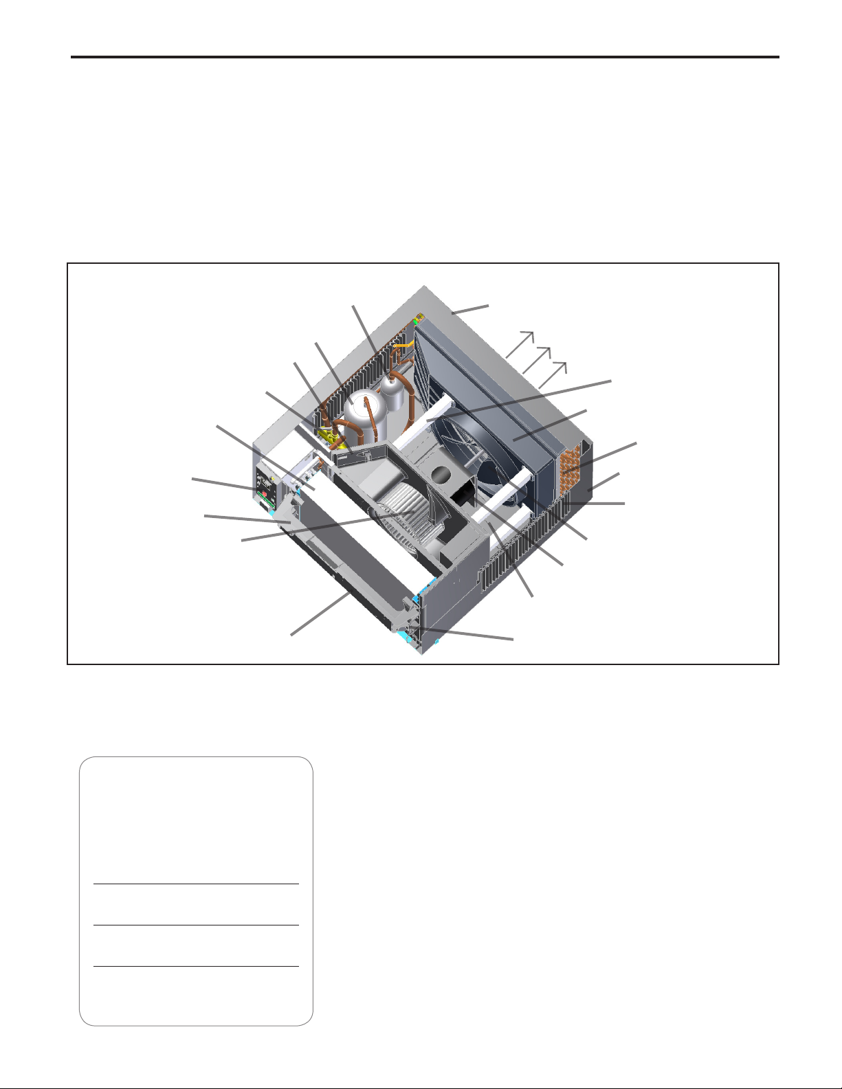
COMPONENTS IDENTIFICATION
Accumulator
Compressor
Outdoor Grille
Discharge Air
Fresh Air Vent
Reversing Valve
Evaporator Coil
Shroud brace
Condense/Fan Shroud
Condenser Coil
Electronic Control
Board
Control Key Pad
Support Bar
Blower Wheel
Air Intake From
Sides and Bottom
Control Key Pad
(User Interface)
IMPORTANT: It will be necessary for you to accurately identify the unit you are servicing, so you can be certain of a
proper diagnosis and repair (See Unit Identication code on page 6).
Chassis Pull
Out Handle
Fan/Blower Motor
Base Pan
Sleeve
Air Intake Vents
Fan Blade
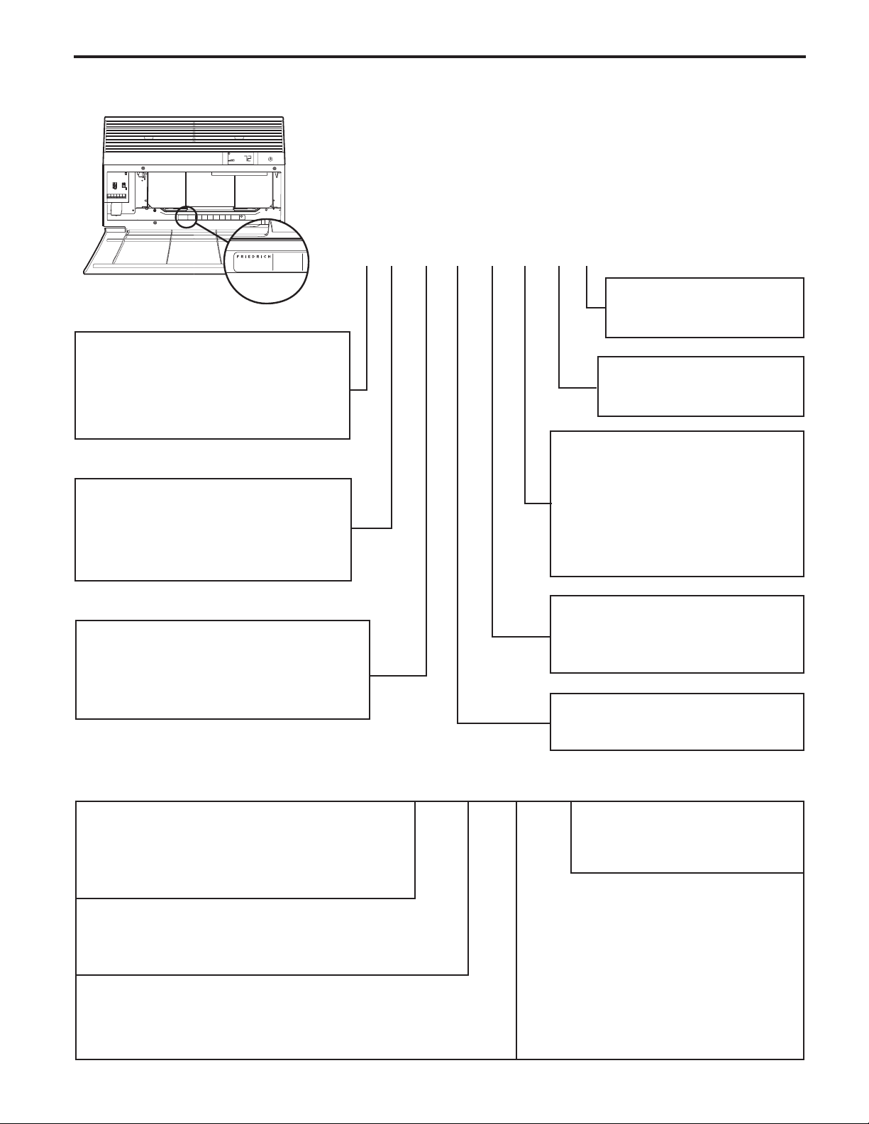
MODEL AND SERIAL NUMBER LOCATION
Register your air conditioner
Model information can be found on the name
plate behind the front cover.
For your future convenience, record the model
information here.
MODEL NUMBER
SERIAL NUMBER
PURCHASE DATE
5
Page 7
UNIT IDENTIFICATION
COOLING
VOLTS 115
MODEL NUMBER
HEATING
REFRIGERANT
XXXXXXXXX
XXXXXXXXXX
FUSE PROTECTED
U
L
BTH/HR 6500
60 HZ / 1 PH
YS10M10A
BTH/HR 6500
30.1 OZ R410A
600 PSIG HS
XXXXXXXXX
CIRCUITS USE 15A
AIR CONDITIONING CO.
VOLTS MIN 108
SERIAL NUMBER
SAN ANTONIO, TEXAS
LICY00008
ASSEMBLED IN MEXICO
X XX
EER 12.0
EER 10.4
300 PSIG LS
XXXXXXXXXX
TIME DELAY FUSE
XXXXX
AMPS 8.0
AMPS 7.0
XXXXXXXXXX
XXXXXXXXXX
Model Number Code
MODEL NUMBER
YS10M10A
AIR CONDITIONING CO.
SERIAL NUMBER
SAN ANTONIO, TEXAS
LICY00008
ASSEMBLED IN MEXICO
1st Digit – Function
S = Straight Cool, Value Series
Y = Heat Pump
E = Electric Heat
2nd Digit
S = Small Chassis
M = Medium Chassis
L = Large Chassis
3rd and 4th Digit - Approximate
BTU/HR in 1000s (Cooling)
Heating BTU/Hr capacity listed in the
Specication/Performance Data Section
S S 08 M 1 0 B A
9th Digit, Engineering Sufx
Major modication
Subject to change
8th Digit, Marketing Sufx
Indicates modication
Subject to change
7th Digit – Options
0 = Straight Cool &
Heat Pump Models
3 = 3 KW Heat Strip, Nominal
4 = 4 KW Heat Strip, Nominal
5 = 5 KW Heat Strip, Nominal
6th Digit – Voltage
1 = 115 Volts
3 = 230-208 Volts
5th Digit
Alphabetical Modier
RAC Serial Number Identication Guide
Serial Number
Decade Manufactured
L=0 C=3 F=6 J=9
A=1 D=4 G=7
B=2 E=5 H=8
Year Manufactured
A=1 D=4 G=7 K=0
B=2 E=5 H=8
C=3 F=6 J=9
Month Manufactured
A=Jan D=Apr G=Jul K=Oct
B=Feb E=May H=Aug L=Nov
C=Mar F=Jun J=Sept M=Dec
6
A B A R 00001
Production Run Number
Product Line
R = RAC
Page 8
LISTED
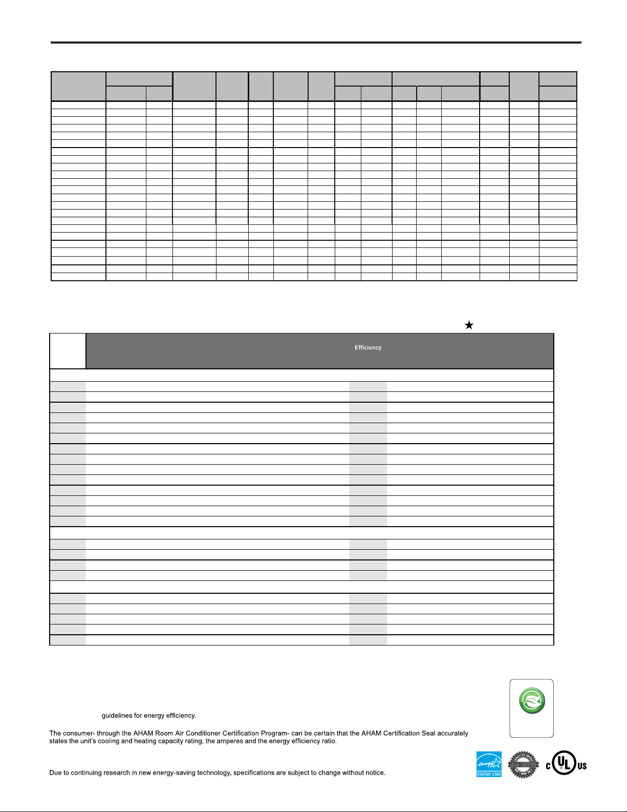
REFRIGERATION SYSTEM PERFORMANCE DATA
COOLING
PERFORMANCE
DATA*
SS08N10-A 54 26 114 153 65 7 19 151 400 6.1 32.0 26.0 115 15
YS10N10-A 59 21 115 155 67 12 14 147 395 7.8 7.6 50.0 26.5 115 15
SS10N10-A 54 26 114 157 68 16 17 137 392 7.7 50.0 27.0 115 15
SS12N10-A 56 24 119 170 60 14 25 135 423 10.0 55.0 30.0 115 15
SS14N10-A 55 25 120 171 62 14 23 141 390 12.0 63.0 31.0 115 15
SS12N30-A 47 33 114 155 58 10 18 134 393 4.8 30.0 31.5 230/208v 15
YS12N30-A 61 19 118 169 69 18 21 137 413 5.2 26.0 32.0 230/208v 20
SS15N30-A 54 26 119 174 59 12 34 127 420 6.4 32.0 33.5 230/208v 15
ES15N33-A 54 26 119 174 59 12 34 127 420 6.4 16.0 32.0 33.5 230/208v 20
SM15N10-A 55 25 118 153 58 10 18 140 410 12.
SM18N30-A 57 23 120 169 61 14 22 136 422 7.4 42.0 39.5 230/208v 15
SM21N30-A 60 20 123 175 65 10 20 130 448 9.4 46.0 40.0 230/208v 15
SM24N30-A 45 35 127 175 50 10 28 119 457 11.2 60.5 43.6 230/208v 20
EM24N34-A 45 35 127 175 50 10 28 119 457 11.2 19.5 60.5 43.5 230/208v 30
YL24N35-A 58 22 119 174 64 22 20 124 417 11.1 12.2 47.0 73.0 230/208v 30
SL22N30-A 54 26 119 159 59 10 20 139 409 9.4 48.0 57.0 230/208v 15
SL24N30-A 54 26 123 163 58 16 19 132 435 11.2 47.0 69.0 230/208v 20
SL28N30-A 54 26 122 173 60 11 26 139 445 12.7 60.0 70.5 230/208v 20
SL36N30-A 52 28 130 190 56 13 33 126 480 18.0 88.0 72.0 230/208v 30
EL36N35-A 52 28 130 190 56 13 33 126 480 18.0 24.0 88.0 72.0 230/208v 30
EVAP. AIR TEMP. DEG.
F
Discharge Air
Temp.
Drop F.
CONDENSER
TEMP DEG. F
Discharge
120 169 61 14 22 136 422 7.4 42.0 39.5 230/208v 30
Temp
Suction
Temp
Super Heat
Sub-
Cooling
OPERATING
PRESSURES
Suction Discharge
ELECTRICAL RATINGS
Amps
Cool
6 63.0 37.0 115 15
Locked Rotor
Amps
Heat
16.0ES12N33-A 47 33 114 155 58 10 18 135 393 4.8 30.0 31.5 230/208v 20
19.5EM18N34-A 57 23
8.5YM18N34-A 48 32 118 169 53 10 21 126 413 8.5 44.0 40.0 230/208v 30
Amps
5.6
R-410A
REF.
Charge in
OZ.
*Rating Conditions: 80 degrees F, room air temp. & 50% relative humidity, with 95 degree F, outside air temp & 40% relative humidity, all
systems use R-410A. Test done at highest unit fan speed.
Voltage
BREAKER
60 Hertz
FUSE
Amps
SPECIFICATIONS
Energy
Volts
MODEL Cooling Btu Heating Btu
®
Kühl
SS08N10 7900 - 115 6.1 677 - - 11.7 $54 - 1.0 265 S 99 121
*
SS10N10 9500 - 115 7.7 848 - - 11.2 $67 - 2.0 260 S 106 136
*
SS12N10 12000 - 115 10.0 1111 - - 10.8 $88 - 3.0 300 S 112 136
*
SS14N10 14000 - 115 12.0 1444 - - 9.7 $115 - 3.5 325 S 116 133
SS12N30 11500/11200 - 230/208 4.8/4.9 1055/1027 - - 10.9/10.9 $84 - 2.8 275 S 112 134
*
SS15N30 14500/14300 - 230/208 6.4/6.8 1480/1459 - - 9.8/9.8 $112 - 3.5 360 S 116 136
SM15N10 14800 - 115 12.0 1358 - - 10.9 $109 - 3.5 360 M 141 154
*
SM18N30 17500/17200 - 230/208 7.4/8.0 1635/1607 - - 10.7/10.7 $131 - 4.6 350 M 140 158
*
SM21N30 20500/20000 - 230/208 9.4/10.3 2181/2128 - - 9.4/9.4 $173 - 6.0 425 M 132 153
*
SM24N30 22300/22000 - 230/208 11.2/11.9 2590/2550 - - 8.6/8.6 $206 - 10.0 390 M 152 167
SL22N30 21000/20500 - 230/208 9.6/10.2 2188/2092 - - 9.6/9.8 $174 - 6.0 625 L 191 212
*
SL24N30 24000/23800 - 230/208 11.2/12.0 2553/2532 - - 9.4/9.4 $207 - 7.0 640 L 192 213
*
SL28N30 27500/27000 - 230/208 13.5/14.4 2926/2872 - - 9.4/9.4 $229 - 8.5 600 L 193 214
*
SL36N30 36000/35700 - 230/208 19.0/20.5 4235/4200 - - 8.5/8.5 $338 - 12.0 725 L 212 227
®
+ Heat Pump
Kühl
YS10N10* 9400 7500 115 7.8 855 7.6 743 11.0 $68 3.0 1.9 285 S 109 131
*
YS12N33 11500/11300 9400/9000 230/208 5.2/5.4 1095/1076 5.6/5.8 1132/1139 10.5/10.5 $87 2.4/2.3 3.0 265 S 115 136
*
YM18N34 18200/17800 17900/17700 230/208 8.5/8.9 1808/1788 8.5/8.7 1833/1761 9.9/9.9 $147 2.5/2.6 5.4 370 M 141 152
*
YL24N35 23500/23000 23500/23000 230/208 11.1/12.0 2500/2447 12.2/14.3 2610/2575 9.4/9.4 $199 2.6/2.6 7.0 600 L 197 212
*
®
Kühl
+ Electric Heat
ES12N33 11500/11200 10700/8900 230/208 4.8/4.9 1055/1027 16.0/14.7 3500/2900 10.9/10.9 $84 - 2.8 275 S 113 128
ES15N33 14500/14300 10700/8900 230/208 6.4/6.8 1480/1459 16.0/14.7 3500/2900 9.8/9.8 $112 - 3.5 360 S 117 133
EM18N34 17500/17200 13000/10600 230/208 7.4/8.0 2590/2550 19.5/17.
EM24N34 22300/22000 13000/10600 230/208 11.2/11.9 2590/2550 19.5/17.0 4200/3500 8.6/8.6 $207 - 10.0 390 M 153 166
EL36N35 36000/35700 17300/14300 230/208 19.0/20.5 4235/4200 24.0/22.4 5500/4650 8.5/8.5 $338 - 12.0 725 L 213 225
* Operates on 115 volt and is not equipped with supplemental heat. Will not provide heat at temperatures below 40°F.
Friedrich room air conditioners are designed to operate in outdoor temperatures from 60°
Kühl+ Heat Pump heating information (shown in red) indicates heat pump per formance. Kühl+ and Chill+ Electric Heat heating information
(shown in red) indicates electric heat strip performance. For Kühl+ Heat Pump electric heating performance
Electric Heat model.
®
As an ENERGY STAR
ENERGY STAR
partner, Friedrich Air Conditioning Co. has determined that the selected ENERGY STAR® models meet the
®
Rated
Cooling
Amps
Cooling
Watts
Heating
Amps
Heating
Watts
0 4200/3500 8.6/8.6 $131 - 4.6 350 M 141 158
F to 115° F.
Ratio
Estimated
Yearly
Operating
EER
Cost COP
refer to corresponding Kühl+
ENERGY STAR
Moisture
Removal -
Pints/HR CFM Sleeve
All models use
environmentally
friendly R-410A
®
models
Net WtShip
R-410A
refrigerant.
Wt.
Estimated yearly operating cost based on a 2007 national average electricity cost of 10.65 cents per kWh.
7
Page 9
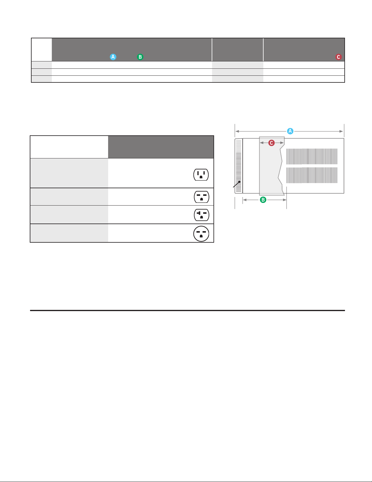
Installation Information / Sleeve Dimensions
Sleeve
Height Width
Depth
with Front
Shell Depth to
Louvers
Minimum
Extension
Into Room*
Minimum
Extension
Outside*
Window Width
Thru-the-wall Installation
Finished Hole
Minimum** Maximum Height Width Max. Depth
S 15
15
/16
" 25
15
/16
" 29"
8
¾"
5
¾”
16
15
/16
” 27
3
/8
" 42 " 16
3
/16”
26
3
/16”
7
3
/8
"
M 17
15
/16
" 25
15
/16
" 29"
8
¾"
5 ¾”
16
15
/16
” 27
3
/8
" 42 " 18
3
/16”
26
3
/16”
7
3
/8
”
L 20
3
/16"
28" 35 ½”
16
½"
5
3
/8
” 18
15
/16
” 29
7
/8
” 42" 20
3
/8
" 28 ¼" 15
1
/8
”
For the best cooling performance and highest energy efficiency
* Minimum ex tensions when mounted in a window.
** Minimum widths achieved using one side curtain assembly as opposed to both in a standard installation.
NOTE: S,M and L sleeves may be installed in window with no side kits if properly installed.
Circuit Rating/ Breaker
Model
SS08N10, SS10N10, SS12N10 and
SS14N10, SM15N10, YS10N10
SS12N30, SS15N30, SM18N30 and
SM21N30, S L22N30
SM24N3 0, SL24N30,SL28N3 0,
ES12N33, ES15N33, YS12N33
SL36N30, EM18N34, EM24N34,
EL36N 35, YM18N34 and YL24N35
Circuit Rating
Breaker or
T-D Fuse
125V - 15A 5 - 15P 6
250V - 15A 6 - 15P 4
250V - 20A 6 - 20 P 4
250V - 30A 6 - 30P 4
Plug
Face
(NEMA#)
Power Cord
Length (f t.)
Wall Outlet
Appearance
Front
(C)
(B)
SIDE VIEW
Keep the filter clean
Make sure that your air conditioner is always in top performing condition
.ylralugerretlifehtgninaelcyb
Provide good air flow
Make sure the airflow to and from the unit is clear. Your air conditioner puts the
conditioned air out at the top of the unit, and takes in unconditioned air at the
bottom. Airflow is critical to good operation. It is just as important on the outside
.dekcolbtonsiroiretxetinuehtdnuorawolfriaehttahtgnidliubehtfo
Unit placement
If your air conditioner can be placed in a window or wall that is shaded by a tree
Insulation
Good insulation will be a big help in maintaining desirable comfort levels.
Doors should have weather stri
pping.
windows.
Proper installation of seal gasket
Make sure the seal gasket has been installed properly to minimize noise
and improve effi ciency. If the seal gasket has not been installed, please
refer to the installation instructions.
rosepardgnisU.yltneiciffeeromneveetarepolliwtinueht,gnidliubre hto naro
blinds on the sunny side of the dwelling will also add to your unit’s efficiency.
8
Be sure to caulk around doors and
Page 10

LISTED
ELECTRICAL DATA
Not following the above WARNING could result in re or
electically unsafe conditions which could cause moderate
or serious property damage.
Read, understand and follow the above warning.
WARNING
ELECTRIC SHOCK HAZARD
Turn off electric power before service or
installation.
All electrical connections and wiring MUST be
installed by a qualied electrician and conform to
the National Electrical Code and all local codes
which have jurisdiction.
Failure to do so can result in personal injury or
death.
NOTICE
FIRE HAZARD
Wire Size Use ONLY wiring size recommended for single outlet branch circuit.
Fuse/Circuit Breaker Use ONLY the correct HACR type and size fuse/circuit breaker. Read electrical ratings on unit’s
rating plate. Proper circuit protection is the responsibiity of the homeowner.
Grounding Unit MUST be grounded from branch circuit through service cord to unit, or through separate
ground wire provided on permanently connected units. Be sure that branch circuit or general
purpose outlet is grounded.
Receptacle The eld supplied outlet must match plug on service cord and be within reach of service cord.
Do NOT alter the service cord or plug. Do NOT use an extension cord. Refer to the table above
for proper receptacle and fuse type.
The consumer - through the AHAM Room Air Conditioner Certication Program - can
be certain that the AHAM Certication Seal accurately states the unit’s cooling and
heating capacity rating, the amperes and the energy efciency ratio.
*HACR: Heating Air Conditioning and Refrigeration
9
Page 11
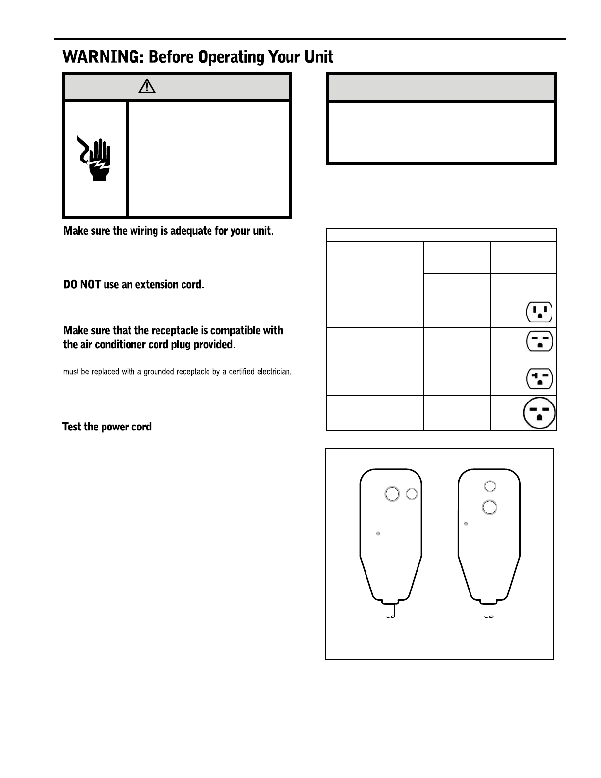
WARNING
NOTICE
Electrical Shock Hazard
Make sure your electrical receptacle has the
same configuration as your air conditioner’s
plug. If different, consult a Licensed Electrician.
Do not use plug adapters.
Do not use an extension cord.
Do not remove ground prong.
Always plug into a grounded 3 prong oulet.
Failure to follow these instructions can result in
death, fire, or electrical shock.
If you have fuses, they should be of the time delay type. Before you install
or relocate this unit, be sure that the amperage rating of the circuit breaker
or time delay fuse does not exceed the amp rating listed in Table 1.
The cord provided will carry the proper amount of electrical power to the
unit; an extension cord may not.
Proper grounding must be maintained at all times. Two prong receptacles
The grounded receptacle should meet all national and local codes and
ordinances. You must use the three prong plug furnished with the air
conditioner. Under no circumstances should you remove the ground
prong from the plug.
Do not use the LCDI device as an ON/OFF switch.
Failure to adhere to this precaution may cause
premature equipment malfunction.
Once plugged in, the unit will operate normally without the need to reset
the LCDI device. If the LCDI device fails to trip when tested or if the power
supply cord is damaged, it must be replaced with a new power supply cord
from the manufacturer. Contact our Technical Assistance Line at (800)
541-6645. To expedite service, please have your model number available.
Table 1.
MODEL
SS08N10, SS10N10,
SS12N10, SS14N10,
SM15N10,
YS10M10
SS12N30, SS15N30,
SM18N30,
SM21N30
SL22N30
SL24N30, SL28N30,
ES12N33, ES15N33,
YS12N33
SL36N30, EM18N34,
EL36N35,
EM24N34, 30 250 6-30R
YM18N34, YL24N35
CIRCUIT RATING
OR TIME DELAY
FUSE
AMP VOLT
15 125 5 -15R
15 250 6-15R
20 250 6-20R
REQUIRED
WALL
RECEPTACLE
NEMA
NO.
All Friedrich room air conditioners are shipped from the factory with a
Leakage Current Detection Interrupter (LCDI) equipped power cord. The
LCDI device on the end of the cord meets the UL and NEC requirements
for cord connected air conditioners.
To test your power supply cord:
1. Plug power supply cord into a grounded 3 prong outlet.
2. Press RESET (See Figure 1).
3. Press TEST, listen for click; the RESET button trips and pops out.
4. Press
and release RESET (Listen for click; RESET button latches
and remains in). The power cord is ready for use.
Note: in case of power failure, unit will resume operation
according to the last input settings.
Figure 1
RESET
TEST
WARNING
TEST BEFORE EACH USE
1. PRESS RESET BUTTON
2. PLUG LCDI INTO POWER
RECEPTACLE
3. PRESS TEST BUTTON,
RESET BUTTON SHOULD
POP UP
4. PRESS TEST BUTTON,
FOR USE
DO NOT USE IF ABOVE TEST
FAILS
WHEN GREEN LIGHT IS ON
IT IS WORKING PROPERLY
15/20A LCDI Device 30A LCDI Device
TEST
RESET
WARNING
TEST BEFORE EACH USE
1. PRESS RESET BUTTON
2. PLUG LCDI INTO POWER
RECEPTACLE
3. PRESS TEST BUTTON,
RESET BUTTON SHOULD
POP UP
4. PRESS TEST BUTTON,
FOR USE
DO NOT USE IF ABOVE TEST
FAILS
WHEN GREEN LIGHT IS ON
IT IS WORKING PROPERLY
FRR001
10
Page 12
Kuhl Control Options
Kühl Control Options
The
Kühl gives you a variety of options for control, programming, and
scheduling including wireless capabilities
Wireless Programming and Control:
The new FriedrichLink™ Adapter (sold seperately) allows you to conviently
control, program and monitor your air conditioning unit remotely from a
smartphone or computer.
FriedrichLink™ Adapter accessory available through Friedrich authorized
retailers or www.friedrich.com. See FriedrichLink™ Adapter section on
www.friedrich.com for complete details.
Pre-Programmed Scheduling Options:
Your unit’s digital control comes equipped with a 24-hour timer and two preprogrammed 7-day energy management options.
24-Hour Timer
The 24-hour timer allows you to turn the unit off and on at pre-set times by
setting an on and off time on the unit control panel. (See page 11 for details on
timer set-up.)
Pre-programmed Energy Management
Your unit comes from the factory with two (2) Pre-programmed
Management settings are shown in Addendum 1 (Residential & Commercial
Schedule Table).
Energy Management Schedule Options are:
1. Residential Schedule – 40 Hr. Work Week
2. Commercial Schedule – 7-Day Business Week
E
nergy
The “Residential” (40 Hr. Work Week) Schedule has four (4) time periods: 06:00,
08:00, 18:00, and 22:00. This option will cause your Kühl Q unit to raise the room
temperature temporarily to 85°F during the hours wh
en most people are away
at work, lower them again to 78°F prior to the time when most people will return
home, and then raise slightly to 82°F to maintain a comfortable temperature
overnight.
The “Commercial” (7-Day Business Week) Schedule has two (2) time periods:
07:00 and 18:00. This option will cause your air conditioner
to raise temperatures
to 84°F after typical working hours and on weekends when commercial spaces
ar
e ty
pically unoccupied.
(See Control Panel Operation Instructions Section)
Customizable Programming Options:
Customizable schedules, with up to four temperature adjustments per day, can
either be uploaded to the unit via the air conditioner’s built-in micro USB interface
or conveniently transmitted wirelessly using the new FriedrichLink™ Adapter
accessory, greatly simplifying the programming of one or multiple units.
See Figure 2.
See www.friedrich.com for complete Customizable
Programming instructions.
Smart Grid
The Kuhl Unit is also able to be controlled by a Smart Grid.
Smart Grid is a network that brings electricity from power stations to
consumers using new technologies that allow power companies to adjust
electrical loads of residential users. Check with your local electric company
to learn more about Smart Grid programs in your area.
Figure 2
FriedrichLink™ Adapter
AIR CONDITIONING CO.
SAN ANTONIO, TEXAS
ASSEMBLED IN MEXICO
MODEL NUMBER
HEATING
REFRIGERANT
XXXXXXXXX
XXXXXXXXXX
VOLTS 115
COOLING
YS10M10A
60 HZ / 1 PH
BTH/HR 6500
SERIAL NUMBER
VOLTS MIN 108
EER 12.0
LICY00008
AMPS 8.0
FUSE PROTECTED
U
L
BTH/HR 6500
30.1 OZ R410A
EER 10.4
AMPS 7.0
X XX
600 PSIG HS
XXXXXXXXX
CIRCUITS USE 15A
XXXXX
300 PSIG LS
XXXXXXXXXX
TIME DELAY FUSE
XXXXXXXXXX
XXXXXXXXXX
11
Page 13
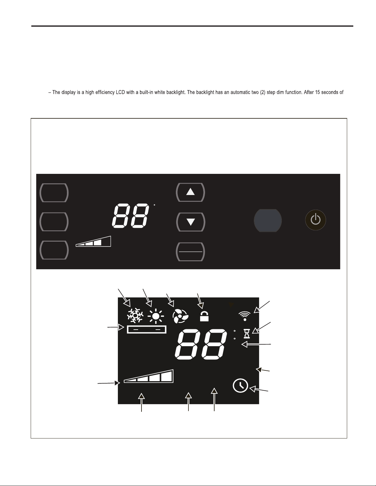
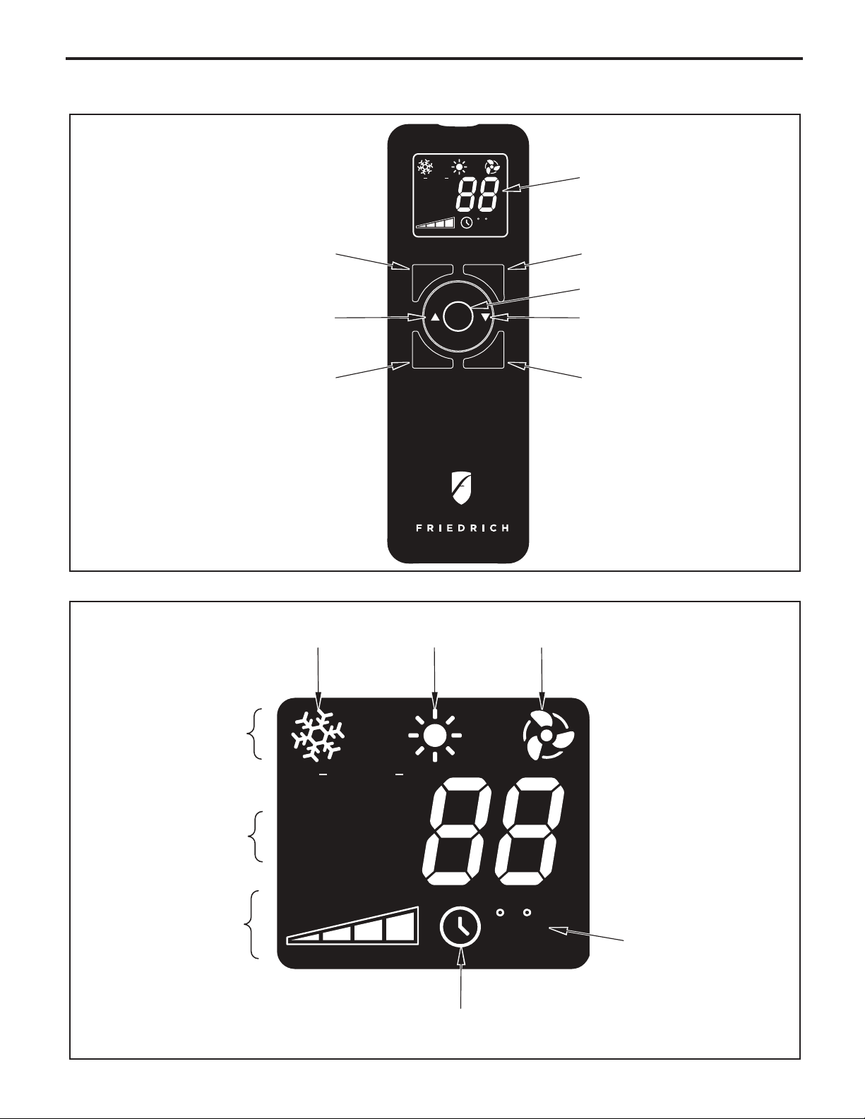
Control Panel and Display Identication
Let’s check out how to control your air conditioner. On the control panel, just above the POWER , is a liquid crystal display (LCD). All of the control panel function
buttons and mode icons can be viewed in Figure 3.
Power On – Press the button to turn on the air conditioner. The power button illuminates to indicate that the power is on. The backlight on the power switch
will automatically dim to 20
% intensity after 15 s
Display
inactivity, the display dims to 20% intensity. After an additional 120 seconds, the display switches off. Touching any button automatically changes the display
to full brightness.
There are three control push buttons on each side of the display.
Figure 3
econds of inactivity. The remote control can also be used to turn power ON / OFF (See Remote Control).
SYSTEM
Cycles between
AUTO, HEAT,
COOL, or FAN
ONLY
(if equipped)
SYSTEM
FAN
MODE
FAN
SPEED
AUTO
Automatically switches
between cool & heat
FAN MODE
Sets fan to either:
- Cycle automatically
- Run continuously
AUTO SPEED
COOL FAN
FAN SPEED
Sets fan speed:
LOW, MED,
HIGH or AUTO
(if equipped)
SET POINT
HEAT
AUTO
AUTO FAN
CONTINUOUS
TEMPERATURE
Increment UP
TEMPERATURE:
Increment DOWN
F
TIMER
SCHEDULE
ONLY
CONTROL
LOCKED
SET POINT
ROOM TEMP
TIMER / SCHEDULE
Turns ON or OFF
F
C
AM
PM
ON OFF
SCHEDULE
:
IR WINDOW
Do not block
ON / OFF
Turns unit on/off
WI-FI
OPERATING
(if equipped)
WAIT
(3 minutes compressor time delay)
2 DIGIT DISPLAY
Shows Setting for:
- Set Point (Temperature)
- Room Temperature
- Clock (AM/PM)
SCHEDULE ON
12
FAN SPEED
Manually selected
fan speed
AUTO SPEED
AUTO SPEED
Automatically selects
best fan cooling or
heating speed
CHECK
FILTER
FILTER
Check / Clean
$MART
TIMER ON
$MART OPERATING
(if equipped)
Page 14
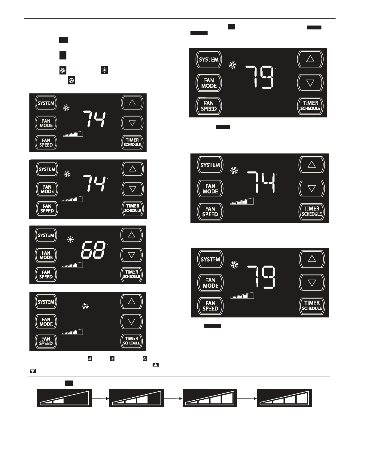
Control Panel Operation Instructions
SYSTEM - The
of operation. To select, press once and let go.
SYSTEM
button allows you to sequentially select the modes
FAN
FAN MODE – The
CONTINUOUS
modes. To select, press once and let go.
MODE
button allows you to select between
AUTO FAN
and
AUTO MODE
COOL MODE
F
AN ONLY MODE
Automatically changes between HEAT and COOL
(HEAT and COOL ONLY Units)
HEAT MODE N
AUTO MODE COOL
- AUTO -
AUTO FAN
SET POINT
COOL ONLY MODE
AUTO FAN
SET POINT
HEAT MODE
AUTO FAN
ot available on some models
F
FRR204
F
FRR103
F
F
AUTO FAN
SET POINT
FRR112
When in the
AUTO FAN
mode, the fan operates only when the system has
a demand to cool or heat the room. Note: the fan is off (no fan speed icon),
indicating no command for cooling or heating.
AUTO FAN (Cooling Demand)
F
AUTO FAN
SET POINT
FRR106
System has a demand for cooling. The fan is operating at a medium speed.
CONTINUOUS
SET POINT
F
CONTINUOUS
SET POINT
FRR113
fan mode, the fan operates all the time. The system
FAN ONLY MODE
FRR104
In the
CONTINUOUS
periodically cools or heats the fan's airfl ow but the fl ow of air does not stop.
When in the SYSTEM COOL or HEAT or FAN ONLY mode, you
FRR105
FAN SPEED - Cooling only units have 4 fan speeds, except models
SL28 and SL36. All Cool+Heat units only have 3 fans speeds.
can also select FAN MODE, FAN SPEED, TIMER SCHEDULE, and
. The SYSTEM MODE does not change.
FAN SPEED - The
FAN
button allows you to toggle between four speeds: LOW, MEDIUM, HIGH, MAX and AUTO speed operation. Press once and let go each time.
SPEED
AUTO
4 Speed
FRR095
During the (SYSTEM mode COOL or HEAT), the fan speed automatically varies depending on the difference between the unit's set point on the control
panel and the actual room temperature. Let me explain. Say for example, you’re working in your garage and you open the big door for several minutes. The
system will sense a wide difference between the set point and the actual room temperature. When this occurs, the system fan speed increases to HIGH for
iod of time. The fan speed decreases, in step, as the temperature difference decreases. When the room temperature matches the system's set point,
a per
fan speed returns to the lowest setting, and if the fan mode is on AUTO FAN, the fan will stop.
13
Page 15

UP and DOWN - arrows - Pressing either or button changes
the system's set point (desired room temperature). These buttons are also
used for setting the Timer and other programming.
F
AUTO FAN
SET POINT
FRR100
F
AUTO FAN
SET POINT
ºF - ºC Select
F
AUTO FAN
SET POINT
FRR132
To switch from degrees Fahrenheit (F) to Celsius (C), press and
buttons simultaneously for three seconds.
FRR101
One press equals 1 degree of change. Holding the button down for more
than 0.6 seconds starts the fast increment/decrement change of the set
point.
TIMER SCHEDULE BUTTON -
TIMER
SCHEDULE
The button has two main uses:
1.Used to preselect a TIMER or SCHEDULE function. (For
pre-selection instructions, please see page 17.)
2. Used to turn on or activate the pre-selected TIMER or
SCHEDULE .
3. To turn on your pre-selction, press the button once and let
TIMER
SCHEDULE
go. The display at bottom right will show the TIMER icon or
SCHEDULE icon .
Example:
TIMER is turned ON SCHEDULE is turned ON
TIMER (FACTORY DEFAULT) - The TIM
ER is the default on new
units. The TIMER function allows you to turn the unit one time ON
and one time OFF daily at the times that you select. For example, you
can command the system to turn ON at 8:15 am and to turn OFF at
1:30 pm everyday. (To set the timer, see page 18.)
SCHEDULE- The SCHEDULE has two options with factory
pre-programmed energy management settings: temperature, system
and time settings (see addendum) (for more information, see page 17).
FRR133
An “F” will flash for 5 seconds and then revert to a normal display. To change
from F to C, press the
or button within 5 seconds.
FRR134
A “C” will fl ash for 5 seconds and then revert to a normal display.
C
AUTO FAN
SET POINT
FRR135
The ºF icon goes away and the ºC icon illuminates on the normal display.
Schedule options are:
1. Residential Schedule - 40 hour work week
2. Commercial Schedule - 5 day business week
(These factory pre-programmed settings can only be changed by using
the WiFi FriedrichLink™ adaptor, or with an upload via the mirco USB
port, with which you can create your own custom program. See page 11.)
14
Page 16
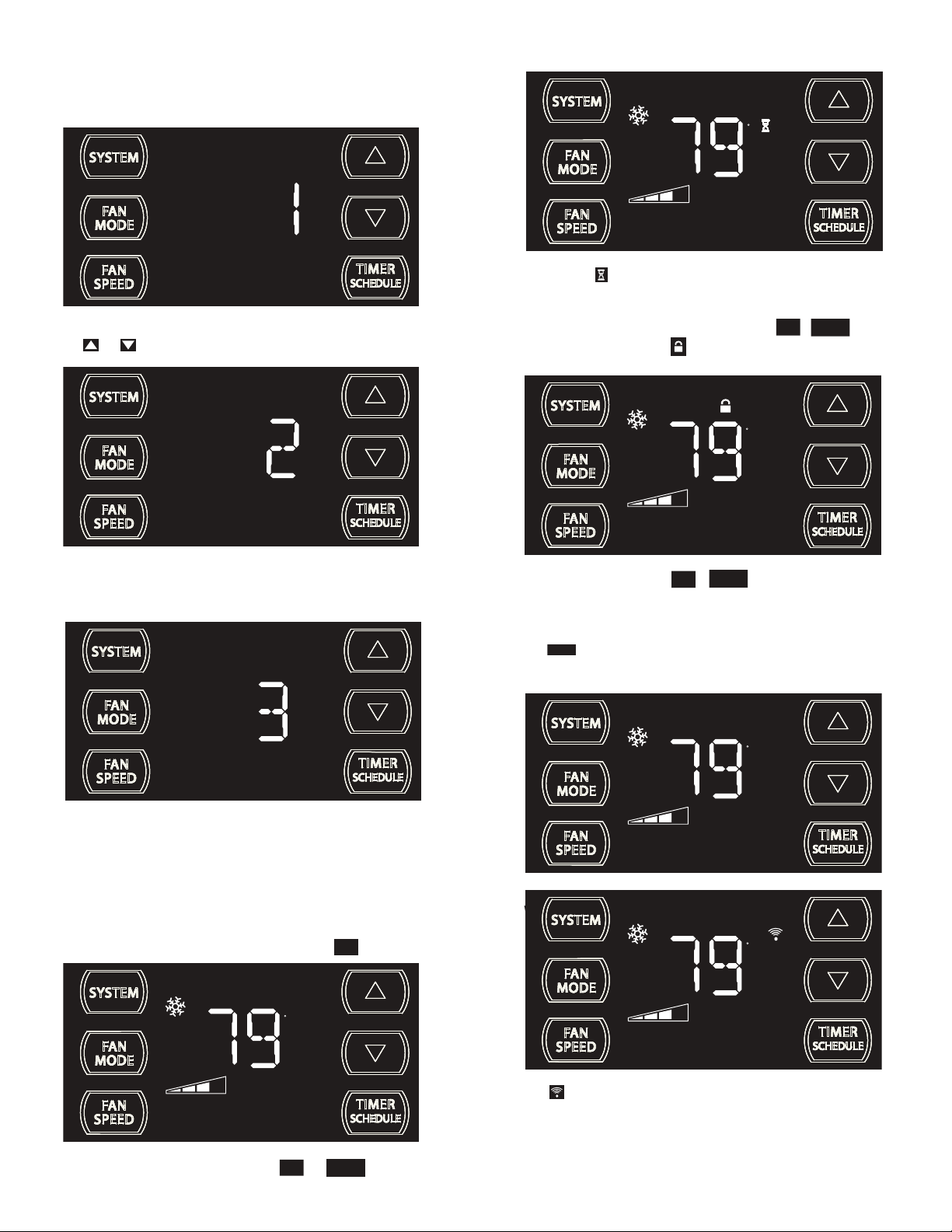
DIM Function
There are three separate display brightness levels, AUTO, 20% and full
(100%). To change the DIM setting, press the Power button for three
seconds.
Wait Icon
F
AUTO FAN
SET POINT
FRR120
The wait icon illuminates when the compressor lockout is active.
FRR192
The 1 indicates a DIM setting of Auto (factory default on new units). Use
the or buttons to change the setting.
FRR193
The 2 indicates a DIM setting of 20%. Press the TIMER SET button within
15 seconds to save the setting. Button inactivity for more than 15 seconds
causes the display to time out and return to the normal operating display.
Control Panel Lock
FAN
To lock the front panel controls, press and hold the
for 3 seconds. The lock icon
illuminates to indicate the locked status.
TIMER
+ buttons
SPEED
SCHEDULE
During lockout, none of the control panel buttons will operate.
F
AUTO FAN
SET POINT
FRR116
To unlock, press and hold the
TIMER
FAN
+ buttons simultaneously for 3
SCHEDULE
SPEED
seconds.
External Control Status
$MART
The icon illuminates to indicate that the system is being controlled
remotely, such as from a smart grid from a power company (for more
information, see page 10).
SMART
F
AUTO FAN
FRR194
The 3 indicates a DIM setting of 100% (full brightness). Press the TIMER
SET (Refer to Figure 8) button within 15 seconds to save the setting.
Button inactivity for more than 15 seconds causes the display to time out
and return to the normal operating display.
Alerts
Check Filter
When the fi lter needs to be cleaned or replaced, the
F
AUTO FAN
SET POINT
CHECK
FILTER
FAN
The alert can be dismissed by pressing the
MODE
15
CHECK
icon displays.
FILTER
TIMER
SCHEDULE
and for 3 seconds.
FRR118
SET POINT
$MART
FRR125
WiFi Connection
F
AUTO FAN
SET POINT
FRR126
The icon illuminates to indicate that the system is receiving a Wi-Fi
connection (for more information, see page 10).
Page 17
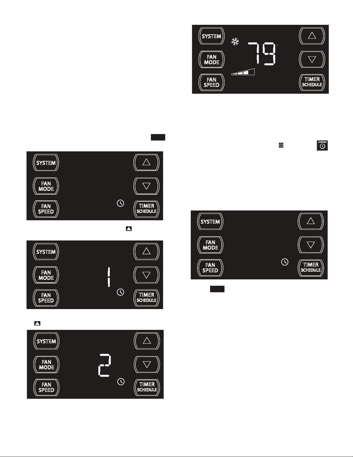
TIMER OR SCHEDULE OPTIONS 1 OR 2 SELECTION
The control system has one Timer and two Schedule functions:
A. Timer (factory default) - Allows you to command the unit to turn
ON and OFF at a time you program. Setting the start, stop and day
can be found latter in this manual on page 18.
B.
Residential Schedule - When selection #1 is selected, the unit
follows a pre-programmed set of operational parameters that
covers 5 days of the week with 4 time windows during each day.
Each time window has it's own set of 8 operating parameters.
Refer to Addendum 1.
C.
Commercial Schedule - When selection #2 is selected, the unit
follows a pre-programmed set of operational parameters that
covers 7 days of the week with 2 time windows during each day.
Each time window has it's own set of 8 operating parameters.
Refer
to Addendum 1.
To change the TIMER/SCHEDULE selection, press and hold the
button for 3 sec, then let go.
TIMER
SCHEDULE
F
AUTO FAN
SET POINT
FRR136
The display reverts to the normal display.
NOTE: The schedule options 1 and 2 have factory pre-programmed
settings which can only be changed by using the WiFi FriedrichLink™
adaptor (an accessory). With it, you can create your own custom
schedule program. See page 10 for more information.
NOTE: Once you have selected the TIMER or SCHEDULE
we must first set the following before turning it on.
1. Set time and day
2. Set start time
3. Set stop time
See timer settings on next page.
FRR139
The display shows the TIMER is selected. Press the button once and
let go.
SCHEDULE
FRR137
The display shows option 1 (Residential Schedule) is selected. Press
the button once and let go.
To Turn On the Timer or Schedule Selected
TIMER
Press the button and let go. The system will operate in the mode
SCHEDULE
option (1, 2 or Timer) you selected. At the above image, TIMER is selected
and turned on.
FRR139
SCHEDULE
The display shows option 2 (Commercial Schedule) is selected.
To save and exit selection, press the TIMER SET button (Figure 4, Page
18).
16
FRR138
Page 18
TIMER SETTINGS
1. Set time and day 2. Set start time 3. Set stop time
Figure 4
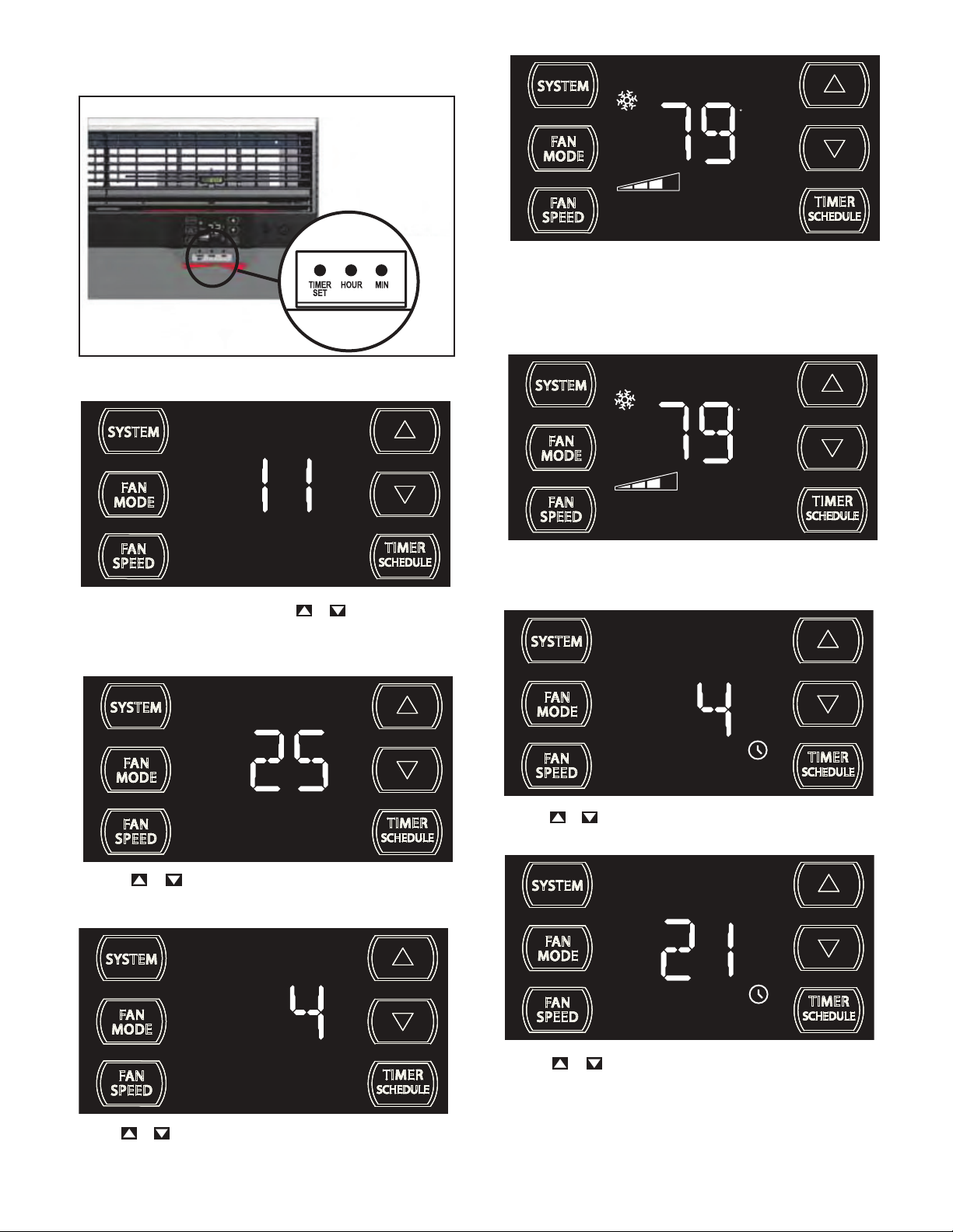
SET TIME AND DAY - To adjust the unit's time press and hold the HOUR
and the MIN buttons for three seconds (Refer to Figure 4).
AM
F
AUTO FAN
SET POINT
FRR131
Press TIMER SET (Refer to Figure 4) button to exit and save the SET
TIME function. The TIMER SET button must be pressed within 15 second.
Button inactivity for more than 15 seconds causes the display to time out
and return to the normal operating display.
Timer Start Time
F
AUTO FAN
SET POINT
FRR128
The unit's current hour displays. Use the or buttons to adjust the
hour. To change from AM to PM continue to increment (roll) the display.
Press TIMER SET (Refer to Figure 4) button to save the hour and display
the unit’s current minutes.
Use the
or buttons to adjust the minutes. The clock is now set
FRR129
for 11:25 AM. Press TIMER SET (Refer to Figure 4) button to display the
unit's day setting.
FRR140
The display shows a normal system. Press and hold the HOUR button
(Figure 4) for 3 seconds. Note: The Timer start-stop times may be set even
when the system is in the Timer or Schedule mode.
AM
ON
FRR141
Use the or button to adjust the hour. Press the TIMER SET button
(Figure 4) to adjust the minutes.
ON
Use the or buttons to adjust the day (1 to 7). The day setting is up
to the user. If you set the current day = 1. So if today is Tuesday, then
Day 1 = Tuesday, select 1.
17
FRR130
FRR142
Use the or button to adjust the minutes. Press the TIMER SET
button (Figure 4) within 15 seconds to exit and save the setting. The timer
is now set to start at 4:21 AM.
The display will return to normal.
Page 19
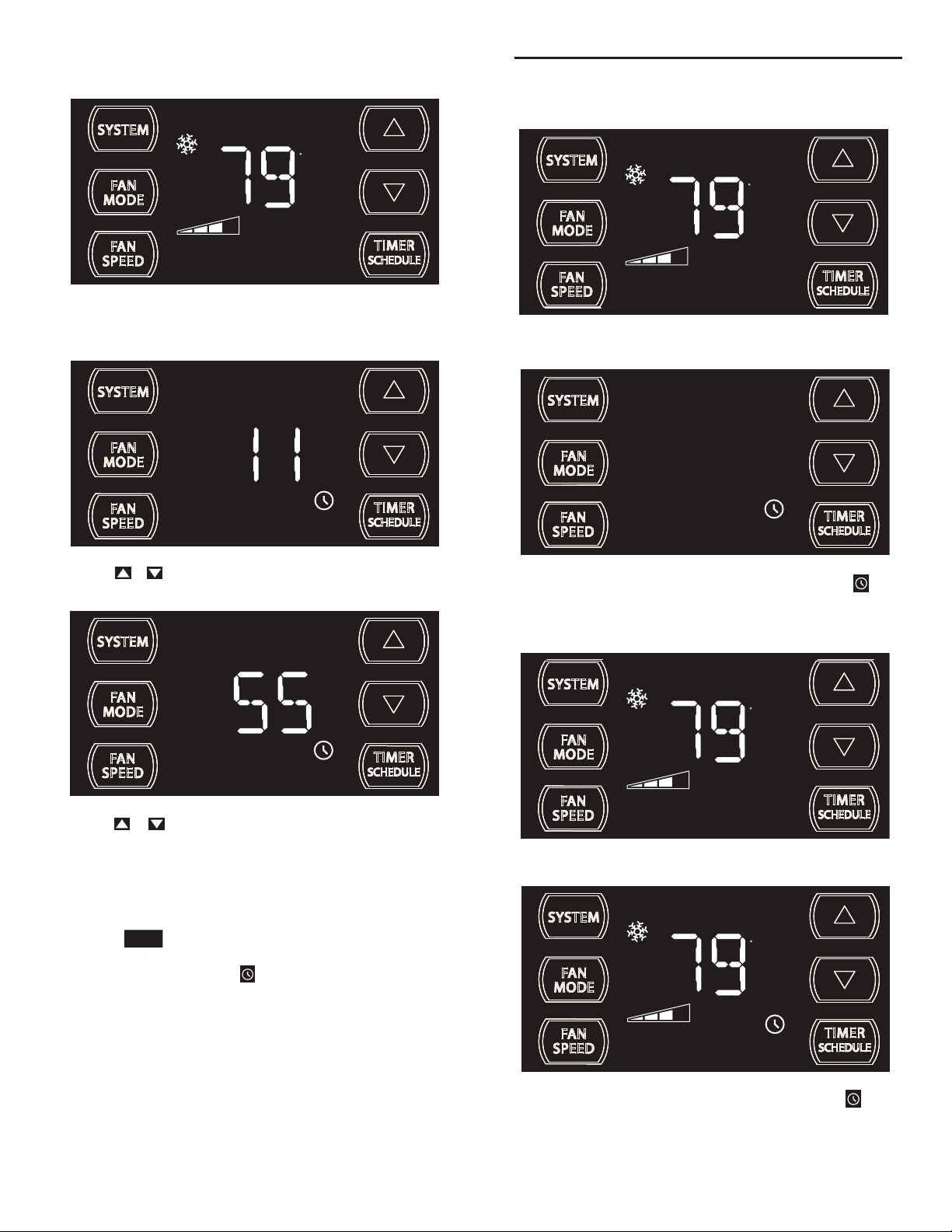
Set theTimer Stop Time
F
AUTO FAN
SET POINT
FRR144
The display shows a normal system. Press and hold the MIN button (Figure
4) for 3 seconds. Note the Timer start - stop times may be set even when
the system is in the Schedule mode.
AM
OFF
Timer ON Scenarios
Scenario 1
F
AUTO FAN
SET POINT
FRR156
The display shows a normal operating system.
FRR145
Use the or button to adjust the hour. Press the TIMER SET button
(Figure 4) to advance to the Minutes section.
OFF
FRR146
Use the or button to adjust the minutes. Press the TIMER SET
button (Figure 4) within 15 seconds to exit and save the setting. The timer
is now set to stop at 11:55 AM. The display returns to normal.
Turning the TIMER ON once the time and day, the start and top times
have been set:
TIMER
Press the button once and let go.
SCHEDULE
NOTE: See the following TIMER ON/OFF scenarios.
FRR157
If the Timer function is turned ON during the Timer’s OFF time, the icon
illuminates. The control system immediately turns the unit OFF.
Scenario 2
F
AUTO FAN
SET POINT
FRR158
The display shows a normal operating system.
F
AUTO FAN
18
SET POINT
FRR159
If the Timer function is turned ON during the Timer’s ON time, the icon
illuminates. The control system immediately turns the unit OFF.
Page 20
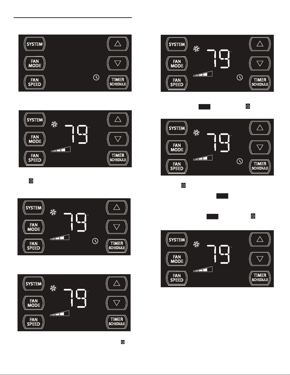
Timer OFF Scenarios
Scenario 1
Timer - Schedule Control Block
F
AUTO FAN
FRR166
The display shows the unit in Timer mode during an in-active (OFF) period.
F
AUTO FAN
SET POINT
FRR167
If the Timer function is turned OFF during an in-active (OFF) period, the
Timer
icon turns off. The display shows a normal system.
Scenario 2
SET POINT
If the unit is operating in the TIMER or SCHEDULE mode, and you press
any bytton except the button, the TIMER icon begins to
TIMER
SCHEDULE
SCHEDULE
FRR148
blink. All button action is blocked.
F
AUTO FAN
SET POINT
SCHEDULE
FRR149
The TIMER icon stops blinking after 3 seconds. You must turn the
active TIMER or SCHEDULE mode OFF before making changes. Once
the changes are made, press the button to re-activate TIMER
TIMER
SCHEDULE
or SCHEDULE mode.
F
AUTO FAN
SET POINT
FRR168
The display shows the unit in Timer mode during an active (ON) period.
F
AUTO FAN
SET POINT
FRR169
If the Timer function is turned OFF during the ON time. The Timer icon
turns off. The control stays in the current state.
The display shows a normal system.
19
If the unit is operating in the TIMER or SCHEDULE mode, and then you
press any button except the button, the TIMER icon begins
TIMER
SCHEDULE
to blink.
F
AUTO FAN
SET POINT
FRR150
All button action is blocked.
Page 21
Remote Control Operation
Remote Control - Refer to Figures 12 and 13 during operation description.
Getting Started - Install two (2) AAA batteries in the battery compartment
located on the back of the unit.
Operation - The remote control should be within 25 feet of the air
conditioner for operation. (Refer to Figure 11 for effectiveness). Press the
power button to turn the remote on. The remote will automatically power
off aft
er 15 seconds if the buttons are not being pressed. The remote must
be on to cont
POWER Button - Turns remote and unit on and off.
SYSTEM Button - Allows the user to sequentially select the
following: AUTO - AUTO -, COOL
operations. When the button is pressed, the display indicates which mode
has been selected via a display message.Note that when the heating
function is not available, the system will
FAN MODE Button - Selects between automatic (
operation. In the
NOTE:
rol the unit.
HEAT
,
automatically skip the HEAT mode.
AUTO FAN
mode, the fan only turns on and off when the
compressor operates or the heat function is enabled.
AUTO FAN
is not available in the FAN ONLY Mode, the display
indicates
CONTINUOUS
. In the
CONTINUOUS
determined by your selection on the
, and FAN ONLY
AUTO FAN
) or
mode, fan speed is
FAN
button.
SPEED
CONTINUOUS
FAN SPEED Button - Used to sequentially select new fan speed, plus
AUTO operation. When the
FAN
button is pressed, the fan speed icon
SPEED
(triangle) changes to indicate the new speed level. Fan speed automatically
varies depending on the set temperature on the control panel and the actual
room temperature. For example if there is a big difference between your
set temperature and the actual room temperature, the system fan speed
increases to HIGH. It remains at this speed until the room temperature
matches the set temperatur
TIMER/SCHEDULE Button - The button turns the schedule
e.
TIMER
SCHEDULE
function on and off. Press the Schedule button once to turn on the
Schedule (Residential, Commercial, or Timer) that has already been
selected on your unit. Pressing the button a second time turns
TIMER
SCHEDULE
the schedule function off.
UP and DOWN Arrows - Pressing either the
(UP) or (DOWN)
button changes the desired room temperature. The factory preset lower
and upper limits are 60°F (16°C) and 99°F (37°C). These buttons are also
used to navigate between function options when using the User Menu or
Maintenance Mode.
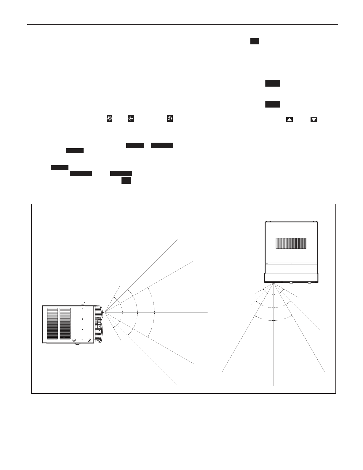
Remote Effectiveness
Hand Held Remote - Has an operating range of up to 25 ft. The infrared
remote control signal must have a clear path to transmit the command to
the air conditioning unit. The remote signal has some ability to "bounce"
off of walls and furniture similar to a television remote control. The diagram
below shows the typical operating range of the control in
with 8 ft high ceilings.
a standard room
Figure 11
SIDE VIEW
TOP VIEW
25ft
25ft
7.5ft
30°
45°
60°
60°
45°
30°
8ft
25ft
25ft
25ft
4ft
8ft
60°
60°
45°
45°
30°
30°
6ft
16ft
25ft
25ft
25ft
Changing Temperature from F˚ (Fahrenheit) To C˚ (Celsius) or Reverse
Be within 25' of unit with the remote control. Press the SYSTEM and FAN MODE buttons at the same time and hold for
3 seconds. The display will show the temperature in Celcius. Do the same to reverse temperature to F
(The remote control operation overrides manual settings on unit)
20
˚ (Fahrenheit).
FRR080
Page 22
Remote Control Operation (Continued)
Figure 12
SYSTEM
TEMPERATURE
UP
FAN SPEED
AUTO
AUTO FAN
CONTINUOUS
AUTO
SYSTEM
FAN SPEED
POWER
F
C
FAN MODE
SCHEDULE
DISPLAY
FAN MODE
POWER
TEMPERATURE
DOWN
SCHEDULE
FRR081
Figure 13
SYSTEM
MODE
FAN
MODE
FAN
SPEED
COOL
ICON
AUTO
AUTO FAN
CONTINUOUS
AUTO
HEAT
ICON
SCHEDULE
ICON
FAN ONLY
ICON
F
C
°F / °C
ICONs
FRR082
21
Page 23
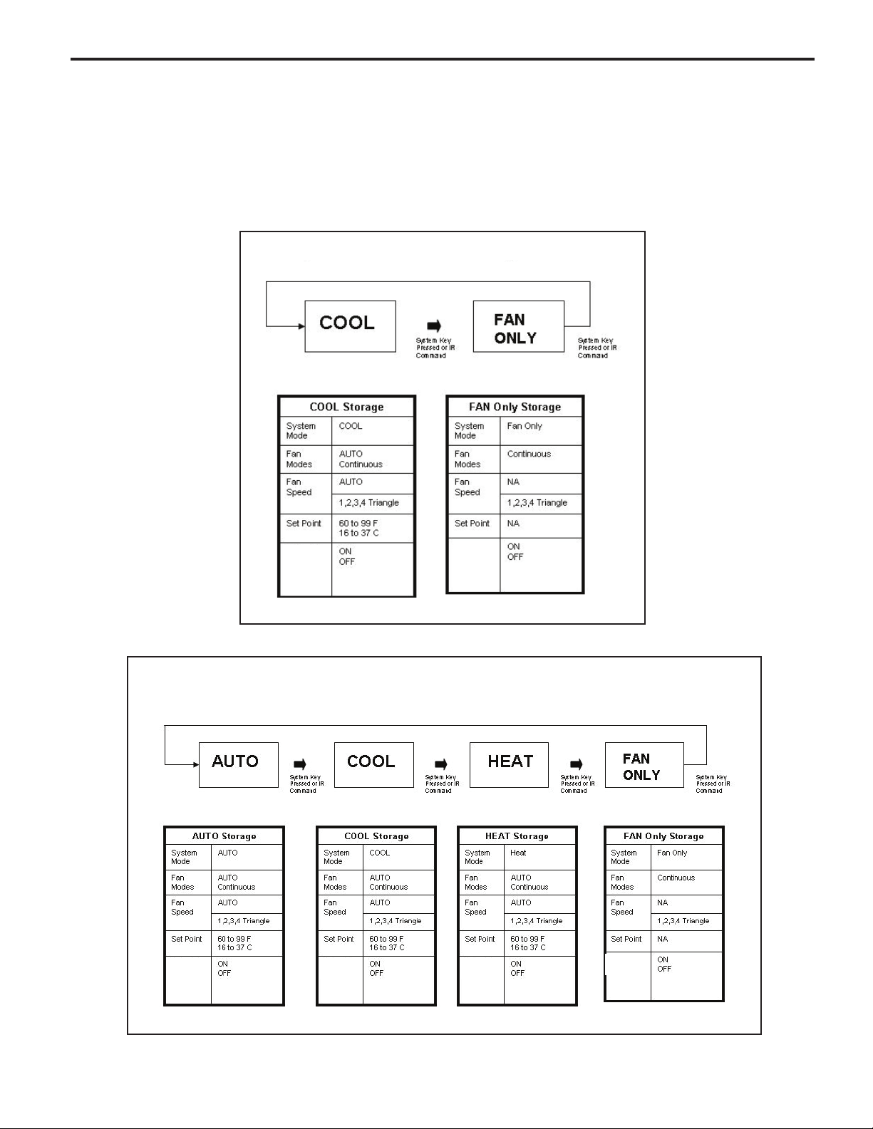
UNIT OPERATION
Front Panel
System Mode Sequence (TIMER/SCHEDULE = OFF)
There are two system modes of operation. One for a cool only unit (see figure 1) and one for a heat-cool unit (see figure 2).
System parameters for each system mode are saved when exiting a system mode, and retrieved when entering a new
system mode.
Figure 1
System Mode: Cool Only Units
Timer/
Schedule
Figure 2
System Mode: Heat - Cool Units
Timer/
Schedule
Timer/
Schedule
Timer/
Schedule
Timer/
Schedule
Timer/
Schedule
22
Page 24
ELECTRONIC CONTROL SEQUENCE OF OPERATION
Compressor and Reversing Valve Control
Active Mode Compressor
Cooling De-Energized
Heat - Heat Pump
Heat - Electric
Fan Only
* The Reversing valve stays in the last state until a call for heat or cooling (see gure below)
On
On
Off
Off
Reversing Valve State
Energized
Compressor Operation:
The reversing valve only changes when required
to provide cooling or heat pump. The RV valve
stays in it's last state until required to change.
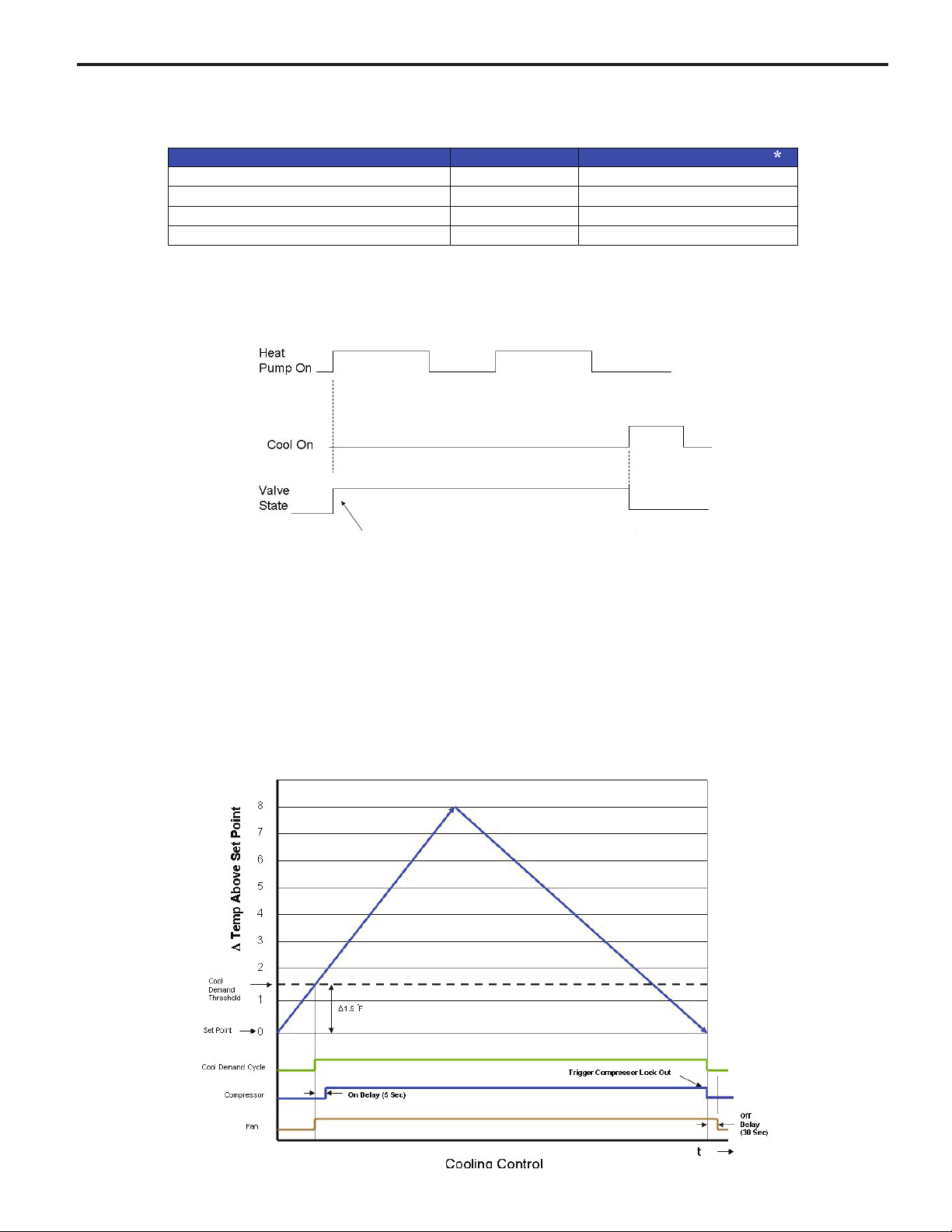
Cooling Mode
Once the ambient temperature rises past the cool demand threshold (Cool Set Point + 1.5 ˚F) (see gure below), and
the compressor is not locked out, the cooling cycle begins. As shown in the gure below, the fan is started 5 seconds
prior to the compressor. Once the ambient temperature has been lowered to the cool set point (Cool Set Point minus
.25 ˚F), the cooling cycle starts to terminate by shutting off the compressor. After a 30 seconds delay, the fan is shut
off. (See gure below for graphic details)
23
Page 25
Heating Mode Control Operation
There are two heating methods: Heat Pump and Electric Resistance Heat.
There are 3 types of units that provide heating: Heat Pump Only (Model YS10M10)
Heat Pump with Electric Heat and Cool with Electric Heat.
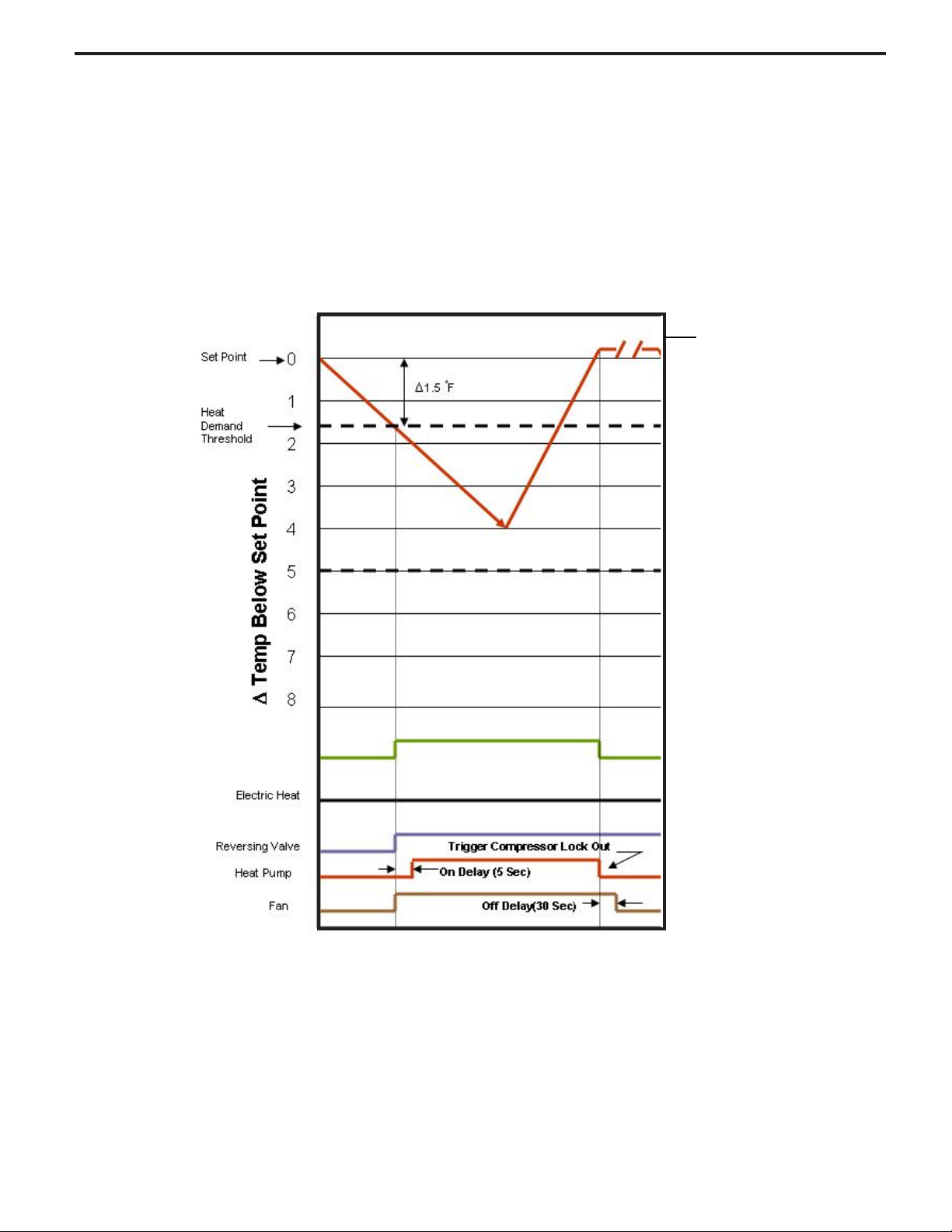
Heat Control Operation Heat Pump Only Unit (YS10M10 has no electric heat back-up)
Once the ambient temperature falls below the Heating Demand Threshold
(1.5 ˚F Below the Heat Set Point Temperature), the heating cycle begins. The fan is turned on 5 seconds before.
Once the ambient temperature has been raised to the Heat Satised Point (Set point + .25 ˚F), the compressor is
turned off. The fan is turned off 15 seconds later. The gure below illustrates the basic heat pump operation.
Satised Point
Heat Control (Heat Pump Only)
YS10M10 Heat Pump Defrost Cycle Operation
The defrost in this unit is an active reverse cycle. The defrost control runs in the background and determines when a
defrost cycle is required. Once initiated, the defrost cycle runs to completion.
The defrost cycle can only be initiated when the heat pump is in operation. The compressor will not be turned off to
avoid activating the compressor's time delay. The reversing valve will be switched to the cool mode position. The
indoor fan/blower will be turned off. Once the defrost cycle is nished, the system should re-enter a heating demand
cycle if required.
When the heat pump run time is 60 minutes or greater with an outdoor coil temperature of 26F degrees or lower, the
control will run an active defrost for up to 6 minutes. When the temperature at the outdoor coil reaches 54F degrees,
the heat pump heat will resume.
24
Page 26
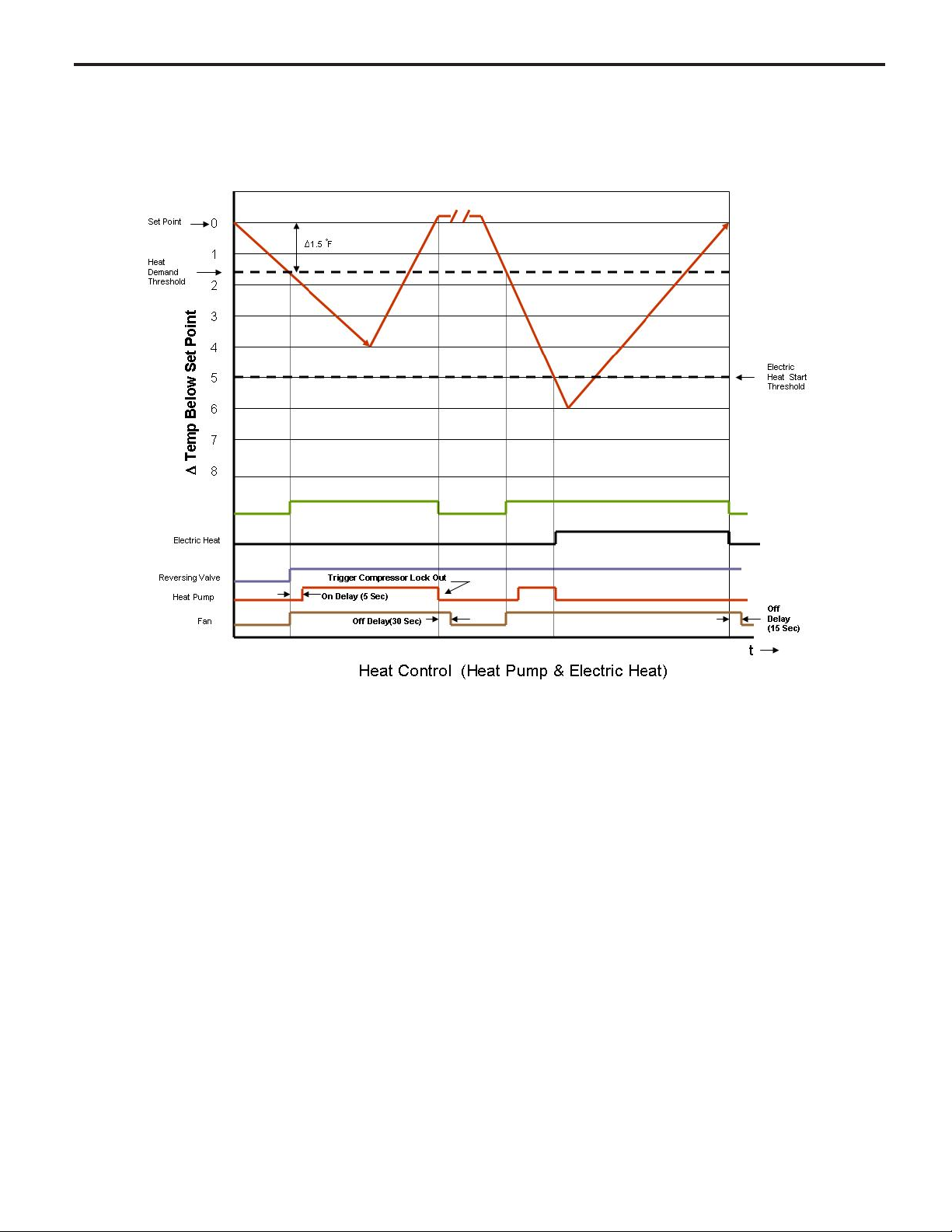
Heat Pump With Electric Heat Operation
This heating is more complex due to the possibility of two heating methods. If the ambient indoor temperature is below the heat demand threshold (1.5˚F below the heat set point temperature), and the compressor is not locked out,
turn on compressor. If the ambient indoor temperature is 0.25˚F above the heat set point turn off the compressor.
If the compressor is locked out & electric heat is available:
1. Turn on the electric heat until the compressor is not locked out.
2. After lockout, turn off the electric heat, wait 5 seconds, then turn on the compressor.
If Electric Heat is Available
After the Heat button is initially pressed, the unit will run the electric heater rst until the initial set point is satised (Hot
Start Feature). After the initial start, the unit will switch to Heat Pump heat and decide between Heat Pump heat and
Electric heat based on the following two monitored conditions:
Condition 1
If the outdoor coil temperature sensor drops to 30 ˚F or less for 2 consecutive minutes, the unit will switch to electric heat
if available. Thereafter, the unit will switch back to Heat Pump heat if the outdoor coil temperature sensor rises to 45 ˚F or
greater.
If Electric Heat is not available (out of order) and the outdoor coil temperature sensor drops to 30 ˚F or less for 2
consecutive minutes, then the compressor and fan will turn off. Thereafter, the unit will switch back to Heat Pump heat if
the outdoor coil temperature rises to 45 ˚F or greater.
25
Page 27

Heat Pump With Electric Heat Operation (Continued)
Condition 2
If the Δ (delta) (set point temperature minus the ambient indoor temperature) is greater than 5 ˚F, then the unit will switch
to electric heat, if available. The unit will continue to operate with electric heat until the heat demand is satised. Note that
the electric heat switches on after the Δ temp passes 5°F and the heat pump switches off. Also note that the electric heat
will run until the heat demand is satised. When another heat demand cycle is initiated, the heat pump will run unless the Δ
temp is greater than the electric heat threshold.
Automatic Emergency Heat
If the sealed system fails with a bad reversing valve or anything that causes the indoor coil to get colder than the indoor
ambient temperature:
1) If the indoor coil thermistor senses a 5 degree temperature drop as compared to the ambient temperature thermistor
and this lasts up to 5 minutes, the control board will switch the unit to electric heat and continue heating with it.
2) At this point, error code 15 is generated; heat pump failure. Indoor coil temperature lower than indoor ambient
temperature for 5 or more degrees for 5 consecutive minutes.
Note: It is Ok to continue to use the unit with the electric heater until the heat pump is repaired.
Electric Heat Operation in Cool with Electric Heat Units
When in the Heat mode, with and without Fan Mode Auto (Fan cycling):
If the indoor ambient temperature is below the Heat Demand Threshold (Heat Set Point minus 1.5 ˚F), turn on electric heat.
If Ambient is 0.3 ˚F above the Heat Set Point turn off the electric heat.
System Mode Auto
This mode provides automatic change over between cool and heat. The auto mode runs based on the room ambient
temperature vs. the Demand Thresholds. It is only available in Heat-Cool Unit.
Notes:
There is a buffer zone between the cool and heat set points where no heating or cooling is allowed to occur. It is critical
that the Cool Demand Threshold be greater than the Heat Demand Threshold by a minimum of 3° while in the Auto
System Mode. For example, if a user enters a value for the Auto Cooling Set Point that violates the minimum Δ 3° rule, the
Auto Heating Set Point will adjust accordingly.
Automatic Change Over Delay (Cool with Heat Units)
The change over delay ensures that any system heating or cooling over shoot does not trigger an opposite demand cycle.
The change over delay = 15 min. This timer blocks the opposite demand cycle from running until the timer expires. As an
example, if the last demand was a cool cycle, and another cool cycle is requested, the timer will not block the request.
However, if the last demand cycle was a cool cycle, and heat cycle is requested, the timer will block the request until the
change over delay is expired.
26
Page 28

Compressor Lock Out Time
The lockout feature ensures that the compressor is de-energized for a period of time. The timer varies randomly
from 180 to 240 seconds
The compressor lockout is initiated every time the compressor is “off” due to:
(1) Satisfying the temperature set point
(2) Changing mode to fan only or heat
(3) Turning the unit off
(4) Control is rst plugged in or power is restored after failure
(5) Line power is restored from a brown out condition
Wait ICON (Hour Glass )
The wait icon will be turned on when the compressor is locked out and during demand for cooling or heat pump
compressor operation. The Wait ICON will be turned off when the condition clears.
Cooling Fan Delay
Fan cycle/Auto mode only
When unit cycles cooling ON – starts the fan 5 seconds EARLY. When unit cycles cooling OFF – DELAYS the fan
off for 30 seconds
Note: this fan delay is disabled during Test Mode
Heating Fan Delay
This is only for fan Mode Auto (Fan cycles with cool/heat operation) and not for continuous fan mode. When unit
cycles Heating ON – starts the fan 5 seconds EARLY. When unit cycles Heating OFF – DELAYS the fan off for 15
seconds
Note: the fan delay is disabled during Test Mode
Fan Speed Change Delay
Relay activation is delayed by a minimum number of seconds. The default for this value is 2 seconds and is used to
eliminate relay chatter.
Fan Only System Mode
The fan is turned on and runs at the specied manually set speed.
Only the Fan is turned on. Cool or Heat operation are off.
(This is different than FAN MODE CONTINUOUS where the fan is on with the cool or heat operation).
Fan Only Rules
1. If the SYSTEM FAN ONLY MODE is selected, the Auto fan mode is disabled, and the fan mode is forced to
continuous. In addition, the auto fan speed is disabled. If the user presses the fan speed key, the menu will skip over
the auto selection. The set point temperature display is off.
2. Any fan speed may be manually selected during Fan Only Mode.
27
Page 29
Fan Operation (Front Panel Mode)
Mode
Heat – Cool – Auto – Fan Only
Models starting with SS, SM have 4 speeds. Models with SL, and all Kuhl+ have 3 speeds
Speed Selection
1 2 3 4 AUTO
AUTO Operation, but never
turns Off. Uses cool set point
or heat set point vs. ambient
temperature. When there is
no demand, operate at the
lowest available speed.
AUTO operation turns On or
Off with heat or cool demand
Uses cool set point or heat
set point vs. ambient
temperature
Fan
Continuous
AUTO
Fan Only
"On" " On" "On" " On"
Turns
On or
Off with
heat or
cool
demand
"On" " On" "On" " On" Disabled
Turns
On or
Off with
heat or
cool
demand
Turns
On or
Off with
heat or
cool
demand
Turns
On or
Off with
heat or
cool
demand
Tabl e
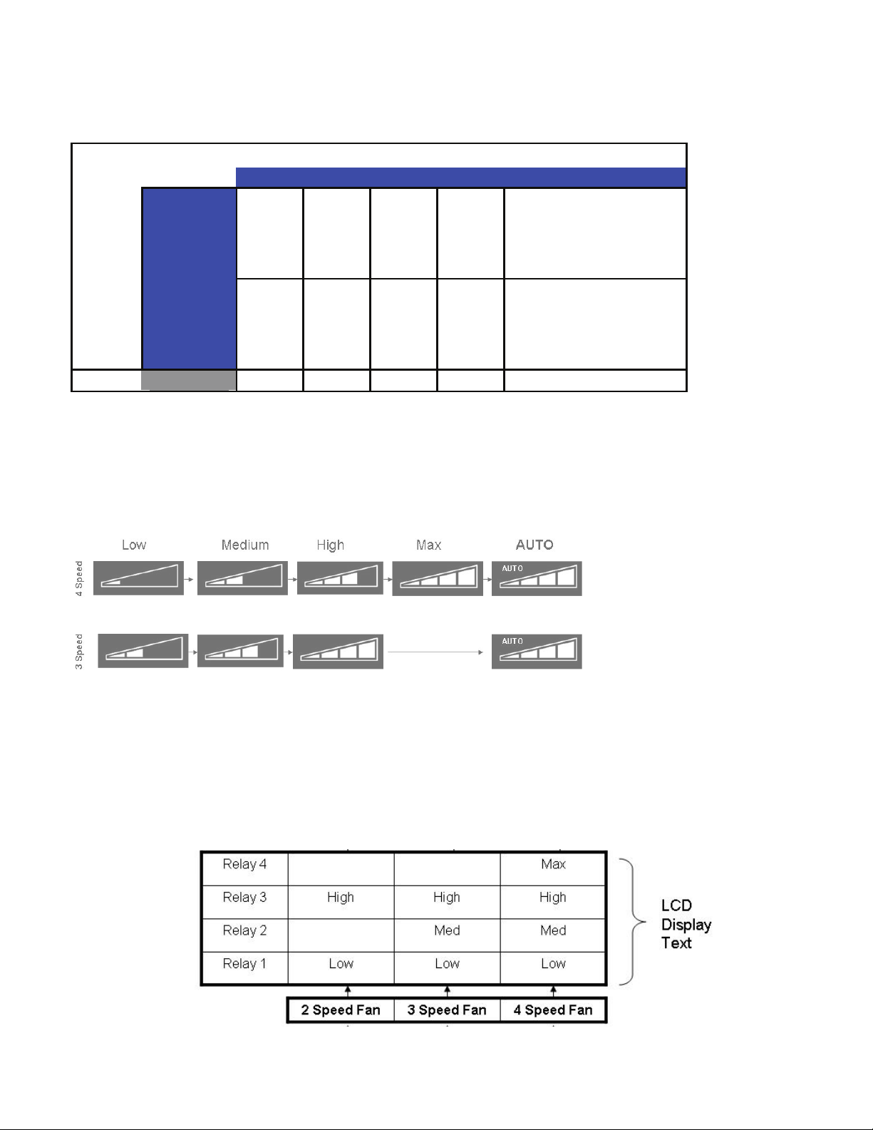
Fan ICON Detail
The system may have a 3 or 4 speed fan. The Fan Speed ICON will Display as per the table below.
Note that in the AUTO mode, the speed of the fan will be shown by illuminating the number of bars in the speed triangle.
Fan Relay Operation
Using the
Front Panel
28
Page 30

REMOVING THE FRONT COVER
REMOVING THE CHASSIS
WARNING
ELECTRIC SHOCK HAZARD
Disconnect power to the unit before
servicing. Failure to follow this warning
could result in serious injury or death.
Remove the decorative front cover by using the tool
provided (see gure below).
WARNING
ELECTRIC SHOCK HAZARD
Disconnect power to the unit before
servicing. Failure to follow this warning
could result in serious injury or death.
Remove the decorative front cover. (See gure at
left). Remove the chassis Entrygard Retainer Wire by
removing the screw at the front right bottom corner
(See Figure below). Save this screw for reattachment
after reinstalling the chassis.
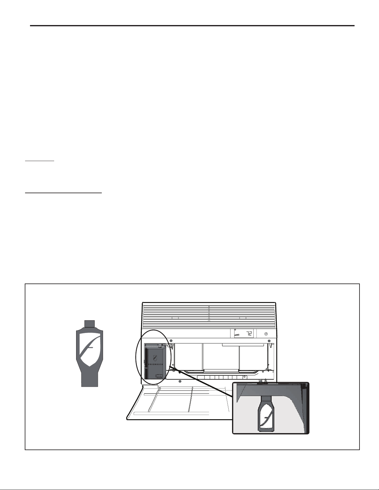
Tighten the four (4) captive screws as indicated by the
arrows in the gure above before closing the front panel
(do not over tighten). Ensure the lter is in place.
Make sure curtains do not block the side air intake
Notes on reattaching the decorative front cover:
Align the cord notch over the cord and center the fresh
air lever. Align the cover over the User Interface
(UI) to ensure it is clear around it and it does not
depress any buttons. If not installed correctly the
wrench alert symbol could ash.
Hold the cabinet stationary then use the hand grips on
both ends of the control unit support bracket to pull the
chassis out of the cabinet (see below).
Before reinserting the chassis into the sleeve ensure to
properly reinstall the chassis seal gasket.
29
Page 31

REPLACING THE INDOOR COIL
THERMISTOR
WARNING
ELECTRIC SHOCK HAZARD
Disconnect power to the unit before
servicing. Failure to follow this warning
could result in serious injury or death.
Remove the decorative front cover (see page 29).
Remove all indicated screws below (8 total, see gure
below). Remove the Discharge Sensor and the User
Interface plugs from the control board.
Replace the indoor coil sensor. Ensure to properly clip
and insulate it at the same location (see gure below).
Remove the screws indicated at the side and back plate
(6 total, see gure below). Partially lift the top cover and
at the same time carefully swing out from the top, the
back and side plate.
Up
Swing
Out
REPLACING THE CONTROL BOARD
WARNING
ELECTRIC SHOCK HAZARD
Disconnect power to the unit before
servicing. Failure to follow this warning
could result in serious injury or death.
Remove the decorative front cover (see page 29).
Disconnect discharge sensor plug (red)
Disconnect the User Interface plug (white)
Remove the 3 screws indicated below.
Pull control board and mount plate out and disconnect
the following connectors from it:
Power, capacitor, thermistors, fan, reversing valve
and heater.
Remove the hex screw holding the control board to
its mount plate. Pull out the control board (see gure
below).
30
30
Page 32

Airflow Selection and Adjustment
Air flow direction adjustment
left or right side of the discharge opening. Each of the banks of louvers
can be directed left, right, up or down in order to achieve the most optimum
move it in the direction that you would like the air to be directed. Please
louvers than the other.
Fresh air and exhaust control
Your air conditioner has the ability to bring fresh air into the room or exhaust
stale air out of the room. The control slide is found on the upper part of
the unit (See Figure).
TO BRING IN FRESH AIR – Move the lever to the Fresh Air
which allows outside air to enter the room. This is useful in fall and spring as
a means of bringing in fresh outside air when using FAN ONLY . It can also
be used in the summer with the compressor in the Cooling Mode if you wish.
EXHAUST INDOOR AIR – Move the lever to the Exhaust
TO
position. This will allow stale air to be expelled to the outside of the dwelling.
This is especially handy in the spring or fall when indoor air tends to get
stale, or after a social gathering involving smokers, or to remove cooking
odors.
BEST PERFORMANCE – Move the lever to the Re -Circulate Position
position
31
FRR008
Page 33

COMPONENTS TESTING
FAN MOTOR
A single phase permanent split capacitor motor is used to drive
the evaporator blower and condenser fan. A self-resetting
overload is located inside the motor to protect against high
temperature and high amperage conditions. (See Figure 23)
WARNING
ELECTRIC SHOCK HAZARD
Disconnect power to the unit before
servicing. Failure to follow this warning
could result in serious injury or death.
BLOWER/FAN MOTOR - TEST
1. Determine that capacitor is serviceable.
2. Disconnect fan motor wires from fan speed switch or
system switch.
3. Apply “live” test cord probes on black wire and common
terminal of capacitor. Motor should run at high speed.
4. Apply “live” test cord probes on red wire and common
terminal of capacitor. Motor should run at low speed.
5. Apply “live” test cord probes on each of the remaining
wires from the speed switch or system switch to test
intermediate speeds. If the control is in the “MoneySaver”
mode and the thermostat calls for cooling, the fan will
start - then stop after approximate
fan and compressor will start together approximately 2
minutes later.
Figure 23
Blower/Fan Motor
ly 2 minutes; then the
CAPACITORS
WARNING
ELECTRIC SHOCK HAZARD
Turn off electric power before servicing.
Discharge capacitor with a 20,000 Ohm 2 Watt
resistor before handling.
Failure to do so may result in personal injury,
or death.
Many motor capacitors are internally fused. Shorting the
terminals will blow the fuse, ruining the capacitor. A 20,000
ohm 2 watt resistor can be used to discharge capacitors
safely. Remove wires from capacitor and place resistor
across terminals. When checking a dual capacitor with a
capacitor analyzer or ohmmeter, both sides must be tested.
Capacitor Check with Capacitor Analyzer
The capacitor analyzer will show whether the capacitor is
“open” or “shorted.” It will tell whether the capacitor is within
its micro farads rating and it will show whether the capacitor
is operating at the proper power-factor percentage. The
instrument will automatically discharge the capacitor when
the test switch is released.
Capacitor Connections
The starting winding of a motor can be damaged by a
shorted and grounded running capacitor. This damage
usually can be avoided by proper connection of the running
capacitor terminals.
From the supply line on a typical 230 volt circuit, a 115 volt
potential exists from the “R” terminal to ground through a
possible short in the capacitor. However, from the “S” or start
terminal, a much higher potential, possibly as high as 400
volts, exists because of the counter EMF generated in the
start winding. Therefore, the possibility of capacitor failure
is much greater when the identied terminal is connected
to the “S” or start terminal. The identied terminal should
always be connected to the supply line, or “R” terminal,
never to the “S” terminal.
32
When connected properly, a shorted or grounded running
capacitor will result in a direct short to ground from the “R”
terminal and will blow the line fuse. The motor protector will
protect the main winding from excessive temperature.
Dual Rated Run Capacitor Hook-up
Page 34

COMPONENTS TESTING (continued)
HEATING ELEMENT
All heat pumps and electric heat models are equipped
with a heating element with the exception of model
YS10M10. The other “YS” and “ES” models are
equipped with a 3.3 KW element. The “YM” and “EM”
models are equipped with a 4.0 KW element. The “YL”
and “EL” models are equipped with a 5.2 KW element.
Heating Element
Sample
The heating element contains a fuse link and a heater
limit switch. The fuse link is in series with the power
supply and will open and interrupt the power when the
temperature reaches 199°F or a short circuit occurs in
the heating element. Once the fuse link separates, a
new fuse link must be installed.
NOTE: Always replace with the exact replacement.
The heater element has a high limit control. This
control is a bimetal thermostat mounted in the top of
the heating element.
Should the fan motor fail or lter become clogged,
the high limit control will open and interrupt power to
the heater before reaching an unsafe temperature
condition.
The control is designed to open at 110°F ±6°F. Test
continuity below 110°F or when it is cooled off.
TESTING THE HEATING ELEMENT
WARNING
ELECTRIC SHOCK HAZARD
Disconnect power to the unit before
servicing. Failure to follow this warning
could result in serious injury or death.
Testing of the elements can be made with an ohmmeter
across the terminals after the connecting wires
have been removed. A cold resistance reading of
approximately 14.5 ohms for the 3.3 KW heater, 11.9
ohms for the 4.0 KW heater and 9.15 ohms for the 5.2
KW heater should be registered.
DRAIN PAN VALVE
During the cooling mode of operation, condensate
which collects in the drain pan is picked up by the con-
denser fan blade and sprayed onto the condenser coil.
This assists in cooling the refrigerant plus evaporating
the water.
During the heating mode of operation, it is necessary
that water be removed to prevent it from freezing during
cold outside temperatures. This could cause the con-
denser fan blade to freeze in the accumulated water
and prevent it from turning.
To provide a means of draining this water, a bellows
type drain valve is installed over a drain opening in the
base pan.
This valve is temperature sensitive and will open when
the outside temperature reaches 40°F. The valve will
close gradually as the temperature rises above 40°F to
fully close at 60°F.
HEATING ELEMENT (Heat Pump Models)
The heating element for the “Y” model is energized
by an outdoor thermistor via the electronic control
board. The outdoor defrost thermistor is adjusted at
a predetermined temperature of approximately 30
degrees Fahrenheit and sensed for two consecutive
minutes, to stop the compressor and turn on the
heating element.
33
Bellows Assembly
Drain Pan Valve
Page 35

If the User Interface does not turn on:
1. Make sure the unit has the proper voltage and that it is turned on.
2. Disconnect the User Interface’s wire harness on the control board.
3. Using a voltmeter, check the top and bottom pins of the male connector (see picture below). There
should be 5VDC
4. If there is no voltage, replace the electronic control board.
6. If the connections and the wire harness are good, replace the User Interface.
User Interface
Control Board
Micro USB port for
KWIFI adaptor and
offline scheduler.
(See page #11)
User Interface
Connector
Check here for
5VDC. If no voltage,
replace board. If
there is 5VDC, check
connections and
cable. If ok, replace
User Interface.
34
Page 36

REFRIGERATION SEQUENCE OF OPERATION
A good understanding of the basic operation of the
refrigeration system is essential for the service technician.
Without this understanding, accurate troubleshooting of
refrigeration system problems will be more difcult and time
consuming, if not (in some cases) entirely impossible. The
refrigeration system uses four basic principles (laws) in its
operation they are as follows:
1. “Heat always ows from a warmer body to a cooler body.”
2. “Heat must be added to or removed from a substance
before a change in state can occur”
3. “Flow is always from a higher pressure area to a lower
pressure area.”
4. “The temperature at which a liquid or gas changes state
is dependent upon the pressure.”
The refrigeration cycle begins at the compressor. Starting
the compressor creates a low pressure in the suction line
which draws refrigerant gas (vapor) into the compressor.
The compressor then “compresses” this refrigerant, raising
its pressure and its (heat intensity) temperature.
The refrigerant leaves the compressor through the discharge
Line as a hot High pressure gas (vapor). The refrigerant
enters the condenser coil where it gives up some of its
heat. The condenser fan moving air across the coil’s nned
surface facilitates the transfer of heat from the refrigerant to
the relatively cooler outdoor air.
When a sufcient quantity of heat has been removed from
the refrigerant gas (vapor), the refrigerant will “condense”
(i.e. change to a liquid). Once the refrigerant has been
condensed (changed) to a liquid it is cooled even further by
the air that continues to ow across the condenser coil.
The RAC design determines at exactly what point (in the
condenser) the change of state (i.e. gas to a liquid) takes
place. In all cases, however, the refrigerant must be
totally condensed (changed) to a Liquid before leaving the
condenser coil.
The refrigerant leaves the condenser Coil through the
liquid line as a warm high pressure liquid. It next will pass
through the refrigerant drier (if so equipped). It is the function
of the drier to trap any moisture present in the system,
contaminants, and large particulate matter.
The liquid refrigerant next enters the metering device. The
metering device is a capillary tube. The purpose of the
metering device is to “meter” (i.e. control or measure) the
quantity of refrigerant entering the evaporator coil.
In the case of the capillary tube this is accomplished (by
design) through size (and length) of device, and the pressure
difference present across the device.
Since the evaporator coil is under a lower pressure (due to
the suction created by the compressor) than the liquid line,
the liquid refrigerant leaves the metering device entering the
evaporator coil. As it enters the evaporator coil, the larger
area and lower pressure allows the refrigerant to expand
and lower its temperature (heat intensity). This expansion is
often referred to as “boiling”. Since the unit’s blower is moving
indoor air across the nned surface of the evaporator coil,
the expanding refrigerant absorbs some of that heat. This
results in a lowering of the indoor air temperature, hence the
“cooling” effect.
The expansion and absorbing of heat cause the liquid
refrigerant to evaporate (i.e. change to a gas). Once the
refrigerant has been evaporated (changed to a gas), it is
heated even further by the air that continues to ow across
the evaporator coil.
The particular system design determines at exactly what
point (in the evaporator) the change of state (i.e. liquid to a
gas) takes place. In all cases, however, the refrigerant must
be totally evaporated (changed) to a gas before leaving the
evaporator coil.
The low pressure (suction) created by the compressor
causes the refrigerant to leave the evaporator through the
suction line as a cool low pressure vapor. The refrigerant
then returns to the compressor, where the cycle is repeated.
35
Suction
Line
Evaporator
Coil
Metering
Device
Refrigerant
Strainer
Discharge
Line
Condenser
Coil
Compressor
Refrigerant Drier
Liquid
Line
Page 37

R-410A SEALED SYSTEM REPAIR CONSIDERATIONS
WARNING
Refrigeration system under high pressure
Do not puncture, heat, expose to ame or incinerate.
Only certied refrigeration technicians should
service this equipment.
R410A systems operate at higher pressures than
R22 equipment. Appropriate safe service and
handling practicces must be used.
Only use gauge sets designed for use with R410A.
Do not use standard R22 gauge sets.
The following is a list of important considerations when working with R-410A equipment
• R-410A pressure is approximately 60% higher than R-22 pressure.
• R-410A cylinders must not be allowed to exceed 125 F, they may leak or rupture.
• R-410A must never be pressurized with a mixture of air, it may become
ammable.
•
Servicing equipment and components must be specically designed for use with R-410A and
dedicated to prevent contamination.
•
Manifold sets must be equipped with gauges capable of reading 750 psig (high side) and 200
psig (low side), with a 500-psig low-side retard.
•
Gauge hoses must have a minimum 750-psig service pressure rating
• Recovery cylinders must have a minimum service pressure rating of 400 psig, (DOT 4BA400
and DOT BW400 approved cylinders).
•
POE (Polyol-Ester) lubricants must be used with R-410A equipment.
• To prevent moisture absorption and lubricant contamination, do not leave the refrigeration
system open to the atmosphere longer than 1 hour.
•
Weigh-in the refrigerant charge into the high side of the system.
• Introduce liquid refrigerant charge into the high side of the system.
• For low side pressure charging of R-410A, use a charging adaptor.
36
• Use Friedrich approved R-410A lter dryers only.
Page 38

R-410A SEALED REFRIGERATION SYSTEM REPAIRS
IMPORTANT
SEALED SYSTEM REPAIRS TO COOL-ONLY MODELS REQUIRE THE INSTALLATION OF A LIQUID LINE DRIER.
EQUIPMENT REQUIRED:
1. Voltmeter
2. Ammeter
3. Ohmmeter
9. High Pressure Gauge - (0 to 750 lbs.)
10. Low Pressure Gauge - (-30 to 200 lbs.)
11. Vacuum Gauge - (0 - 1000 microns)
4. E.P.A. Approved Refrigerant Recovery System
5. Vacuum Pump (capable of 200 microns or less
vacuum.)
6. Acetylene Welder
7. Electronic Halogen Leak Detector capable of
detecting HFC (Hydrouorocarbon) refrigerants.
8. Accurate refrigerant charge measuring device such
as:
a. Balance Scales - 1/2 oz. accuracy
b. Charging Board - 1/2 oz. accuracy
WARNING
RISK OF ELECTRIC SHOCK
Unplug and/or disconnect all electrical power
to the unit before performing inspections,
maintenances or service.
Failure to do so could result in electric shock,
serious injury or death.
WARNING
HIGH PRESSURE HAZARD
Sealed Refrigeration System contains refrigerant
and oil under high pressure.
Proper safety procedures must be followed,
and proper protective clothing must be worn
when working with refrigerants.
Failure to follow these procedures could
result in serious injury or death.
12. Facilities for owing nitrogen through refrigeration tubing
during all brazing processes.
EQUIPMENT MUST BE CAPABLE OF:
1. Recovering refrigerant to EPA required levels.
2. Evacuation from both the high side and low side of the
system simultaneously.
3. Introducing refrigerant charge into high side of the
system.
4. Accurately weighing the refrigerant charge introduced
into the system.
Proper refrigerant charge is essential to proper unit operation.
Operating a unit with an improper refrigerant charge will
result in reduced performance (capacity) and/or efciency.
Accordingly, the use of proper charging methods during
servicing will insure that the unit is functioning as designed
and that its compressor will not be damaged.
Too much refrigerant (overcharge) in the system is just as bad
(if not worse) than not enough refrigerant (undercharge). They
both can be the source of certain compressor failures if they
remain uncorrected for any period of time. Quite often, other
problems (such as low air ow across evaporator, etc.) are
misdiagnosed as refrigerant charge problems. The refrigerant
circuit diagnosis chart will assist you in properly diagnosing
these systems.
An overcharged unit will at times return liquid refrigerant
(slugging) back to the suction side of the compressor eventually
causing a mechanical failure within the compressor. This
mechanical failure can manifest itself as valve failure, bearing
failure, and/or other mechanical failure. The specic type of
failure will be inuenced by the amount of liquid being returned,
and the length of time the slugging continues.
Refrigerant Charging
NOTE: Because the RAC system is a sealed system, service
process tubes will have to be installed. First install a line tap
and remove refrigerant from system. Make necessary sealed
system repairs and vacuum system. Crimp process tube
line and solder end shut. Do not leave a service valve in the
sealed system.
37
Not enough refrigerant (undercharge) on the other hand,
will cause the temperature of the suction gas to increase to
the point where it does not provide sufcient cooling for the
compressor motor. When this occurs, the motor winding
temperature will increase causing the motor to overheat
and possibly cycle open the compressor overload protector.
Continued overheating of the motor windings and/or cycling
of the overload will eventually lead to compressor motor or
overload failure.
Page 39

Method Of Charging / Repairs
The acceptable method for charging the sealed system is the
Weighed in Charge Method. The weighed in charge method is
applicable to all units. It is the preferred method to use, as it is
the most accurate.
The weighed in method should always be used whenever
a charge is removed from a unit such as for a leak repair,
compressor replacement, or when there is no refrigerant
charge left in the unit. To charge by this method, requires the
following steps:
1. Install a piercing valve to remove refrigerant from the
sealedsystem. (Piercing valve must be removed from the
system before recharging.)
2. Recover Refrigerant in accordance with EPA regulations.
WARNING
BURN HAZARD
Proper safety procedures must be followed,
and proper protective clothing must be worn
when working with a torch.
Failure to follow these procedures could
result in moderate or serious injury.
3. Install a process tube to sealed system.
CAUTION
FREEZE HAZARD
Proper safety procedures must be followed,
and proper protective clothing must be worn
when working with liquid refrigerant.
Failure to follow these procedures could
result in minor to moderate injury.
4. Make necessary repairs to system.
5. Evacuate system to 200 microns or less.
6. Weigh in refrigerant with the property quantity of R-410A
refrigerant.
7. Start unit, and verify performance.
WARNING
BURN HAZARD
Proper safety procedures must be followed,
and proper protective clothing must be worn
when working with a torch.
Failure to follow these procedures could
result in moderate or serious injury.
8. Crimp the process tube and solder the end shut.
38
Page 40

WARNING
ELECTRIC SHOCK HAZARD
Turn off electric power before service or
installation.
WARNING
HIGH PRESSURE HAZARD
Sealed Refrigeration System contains refrigerant
and oil under high pressure.
Extreme care must be used, if it becomes
necessary to work on equipment with power
applied.
Failure to do so could result in serious injury or
death.
Undercharged Refrigerant Systems
An undercharged system will result in poor performance
(low pressures, etc.) in both the heating and cooling cycle.
Whenever you service a unit with an undercharge of
refrigerant, always suspect a leak. The leak must be
repaired before charging the unit.
To check for an undercharged system, turn the unit on,
allow the compressor to run long enough to establish
working pressures in the system (15 to 20 minutes).
During the cooling cycle you can listen carefully at the exit
of the metering device into the evaporator; an intermittent
hissing and gurgling sound indicates a low refrigerant
charge. Intermittent frosting and thawing of the evaporator
is another indication of a low charge, however, frosting
and thawing can also be caused by insufcient air over
the evaporator.
Proper safety procedures must be followed,
and proper protective clothing must be worn
when working with refrigerants.
Failure to follow these procedures could
result in serious injury or death.
A check of the amperage drawn by the compressor
motor should show a lower reading. (Check the Unit
Specication.) After the unit has run 10 to 15 minutes,
check the gauge pressures. Gauges connected to system
with an undercharge will have low head pressures and
substantially low suction pressures.
Checks for an undercharged system can be made at
the compressor. If the compressor seems quieter than
normal, it is an indication of a low refrigerant charge.
Overcharged Refrigerant Systems
Compressor amps will be near normal or higher.
Noncondensables can also cause these symptoms.
To conrm, remove some of the charge, if conditions
improve, system may be overcharged. If conditions don’t
improve, Noncondensables are indicated.
Whenever an overcharged system is indicated, always
make sure that the problem is not caused by air ow
problems. Improper air ow over the evaporator coil may
indicate some of the same symptoms as an over charged
system.
An overcharge can cause the compressor to fail, since it
would be “slugged” with liquid refrigerant.
The charge for any system is critical. When the compressor
is noisy, suspect an overcharge, when you are sure that
the air quantity over the evaporator coil is correct. Icing
of the evaporator will not be encountered because the
refrigerant will boil later if at all. Gauges connected to
system will usually have higher head pressure (depending
upon amount of over charge). Suction pressure should be
slightly higher.
39
Page 41

Restricted Refrigerant System
Troubleshooting a restricted refrigerant system can be
difcult. The following procedures are the more common
problems and solutions to these problems. There are two
types of refrigerant restrictions: Partial restrictions and
complete restrictions.
A partial restriction allows some of the refrigerant to
circulate through the system.
With a complete restriction there is no circulation of
refrigerant in the system.
Restricted refrigerant systems display the same symptoms
as a “low-charge condition.”
When the unit is shut off, the gauges may equalize very
slowly.
Gauges connected to a completely restricted system
will run in a deep vacuum. When the unit is shut off, the
gauges will not equalize at all.
A quick check for either condition begins at the evaporator.
With a partial restriction, there may be gurgling sounds
at the metering device entrance to the evaporator. The
evaporator in a partial restriction could be partially frosted
or have an ice ball close to the entrance of the metering
device. Frost may continue on the suction line back to the
compressor.
Often a partial restriction of any type can be found by feel,
as there is a temperature difference from one side of the
restriction to the other.
With a complete restriction, there will be no sound at the
metering device entrance. An amperage check of the
compressor with a partial restriction may show normal
current when compared to the unit speci cation. With a
complete restriction the current drawn may be considerably
less than normal, as the compressor is running in a deep
vacuum (no load.) Much of the area of the condenser will
be relatively cool since most or all of the liquid refrigerant
will be stored there.
The following conditions are based primarily on a system
in the cooling mode.
40
Page 42

HERMETIC COMPONENTS CHECK
WARNING
BURN HAZARD
Proper safety procedures must be followed,
and proper protective clothing must be worn
when working with a torch.
Failure to follow these procedures could
result in moderate or serious injury.
METERING DEVICE
Capillary Tube Systems
WARNING
CUT/SEVER HAZARD
Be careful with the sharp edges and corners.
Wear protective clothing and gloves, etc.
Failure to do so could result in serious injury.
All units are equipped with capillary tube metering devices.
Checking for restricted capillary tubes.
1. Connect pressure gauges to unit.
2. Start the unit in the cooling mode. If after a few minutes
of operation the pressures are normal, the check valve
and the cooling capillary are not restricted.
CHECK VALVE
A unique two-way check valve is used on the reverse cycle
heat pumps. It is pressure operated and used to direct the
ow of refrigerant through a single lter drier and to the
proper capillary tube during either the heating or cooling
cycle.
One-way Check Valve
(Heat Pump Models)
NOTE: The slide (check) inside the valve is made of teon.
Should it become necessary to replace the check valve,
place a wet cloth around the valve to prevent overheating
during the brazing operation.
CHECK VALVE OPERATION
In the cooling mode of operation, high pressure liquid enters
the check valve forcing the slide to close the opposite port
(liquid line) to the indoor coil. Refer to refrigerant ow chart.
This directs the refrigerant through the lter drier and cooling
capillary tube to the indoor coil.
3. Switch the unit to the heating mode and observe the
gauge readings after a few minutes running time. If
the system pressure is lower than normal, the heating
capillary is restricted.
4. If the operating pressures are lower than normal in both
the heating and cooling mode, the cooling capillary is
restricted.
In the heating mode of operation, high pressure refrigerant
enters the check valve from the opposite direction, closing
the port (liquid line) to the outdoor coil. The ow path of
the refrigerant is then through the lter drier and heating
capillary to the outdoor coil.
Failure of the slide in the check valve to seat properly in
either mode of operation will cause ooding of the cooling
coil. This is due to the refrigerant bypassing the heating or
cooling capillary tube and entering the liquid line.
COOLING MODE
In the cooling mode of operation, liquid refrigerant from
condenser (liquid line) enters the cooling check valve
forcing the heating check valve shut. The liquid refrigerant
is directed into the liquid dryer after which the refrigerant
is metered through cooling capillary tubes to evaporator.
(Note: liquid refrigerant will also be directed through the
heating capillary tubes in a continuous loop during the
cooling mode).
HEATING MODE
In the heating mode of operation, liquid refrigerant from
the indoor coil enters the heating check valve forcing the
cooling check valve shut. The liquid refrigerant is directed
into the liquid dryer after which the refrigerant is metered
through the heating capillary tubes to outdoor coils. (Note:
liquid refrigerant will also be directed through the cooling
capillary tubes in a continuous loop during the heating
mode).
41
Page 43

REVERSING VALVE DESCRIPTION/OPERATION
WARNING
ELECTRIC SHOCK HAZARD
Disconnect power to the unit before servicing.
Failure to follow this warning could result in
serious injury or death.
The Reversing Valve controls the direction of refrigerant
ow to the indoor and outdoor coils. It consists of a
pressure-operated, main valve and a pilot valve actuated
by a solenoid plunger. The solenoid is energized during the
heating cycle only. The reversing valves used in the RAC
system is a 2-position, 4-way valve.
The single tube on one side of the main valve body is the
high-pressure inlet to the valve from the compressor. The
center tube on the opposite side is connected to the low
pressure (suction) side of the system. The other two are
connected to the indoor and outdoor coils. Small capillary
tubes connect each end of the main valve cylinder to the
“A” and “B” ports of the pilot valve. A third capillary is a common
return line from these ports to the suction tube on the main
valve body. Four-way reversing valves also have a capillary
tube from the compressor discharge tube to the pilot valve.
The piston assembly in the main valve can only be shifted
by the pressure differential between the high and low sides
of the system. The pilot section of the valve opens and
closes ports for the small capillary tubes to the main valve
to cause it to shift.
NOTE: System operating pressures must be near
normal before valve can shift.
42
Page 44

TESTING THE REVERSING VALVE
SOLENOID COIL
WARNING
ELECTRIC SHOCK HAZARD
Unplug and/or disconnect all electrical power
to the unit before performing inspections,
maintenances or service.
Failure to do so could result in electric shock,
serious injury or death.
The solenoid coil is an electromagnetic type coil mounted
on the reversing valve and is energized during the
operation of the compressor in the heating cycle.
1. Turn off high voltage electrical power to unit.
2. Unplug line voltage lead from reversing valve coil.
3. Check for electrical continuity through the coil. If you
do not have continuity replace the coil.
4. Check from each lead of coil to the copper liquid line
as it leaves the unit or the ground lug. There should
be no continuity between either of the coil leads
and ground; if there is, coil is grounded and must be
replaced.
5. If coil tests okay, reconnect the electrical leads.
6. Make sure coil has been assembled correctly.
NOTE: Do not start unit with solenoid coil removed from
valve, or do not remove coil after unit is in operation. This
will cause the coil to burn out.
Should the valve fail to shift from coooling to heating,
block the air ow through the outdoor coil and allow the
discharge pressure to build in the system. Then switch
the system from heating to cooling.
If the valve is stuck in the heating position, block the air
ow through the indoor coil and allow discharge pressure
to build in the system. Then switch the system from
heating to cooling.
Should the valve fail to shift in either position after
increasing the discharge pressure, replace the valve.
Dented or damaged valve body or capillary tubes can
prevent the main slide in the valve body from shifting.
If you determing this is the problem, replace the reversing
valve.
After all of the previous inspections and checks have
been made and determined correct, then perform the
“Touch Test” on the reversing valve.
CHECKING THE REVERSING VALVE
NOTE: You must have normal operating pressures before
the reversing valve can shift.
WARNING
HIGH PRESSURE HAZARD
Sealed Refrigeration System contains refrigerant
and oil under high pressure.
Proper safety procedures must be followed,
and proper protective clothing must be worn
when working with refrigerants.
Failure to follow these procedures could
result in serious injury or death.
Check the operation of the valve by starting the system
and switching the operation from “Cooling” to “Heating”
and then back to “Cooling”. Do not hammer on valve.
Occasionally, the reversing valve may stick in the heating
or cooling position or in the mid-position.
When sluggish or stuck in the mid-position, part of the
discharge gas from the compressor is directed back to the
suction side, resulting in excessively high suction pressure.
Reversing Valve in Heating Mode
43
Page 45

Touch Test in Heating/Cooling Cycle
WARNING
BURN HAZARD
Certain unit components operate at
temperatures hot enough to cause burns.
Proper safety procedures must be followed,
and proper protective clothing must be
worn.
The only definite indications that the slide is in the midposition is if all three tubes on the suction side of the valve
are hot after a few minutes of running time.
NOTE: A condition other than those illustrated above, and
on Page 44, indicate that the reversing valve is not shifting
properly. Both tubes shown as hot or cool must be the same
corresponding temperature.
Failure to follow these procedures could
result in minor to moderate injury.
Procedure For Changing Reversing Valve
WARNING
HIGH PRESSURE HAZARD
Sealed Refrigeration System contains refrigerant
and oil under high pressure.
Proper safety procedures must be followed,
and proper protective clothing must be worn
when working with refrigerants.
Failure to follow these procedures could
result in serious injury or death.
6. Protect new valve body from heat while brazing with plastic
heat sink (Thermo Trap) or wrap valve body with wet rag.
7. Fit all lines into new valve and braze lines into new
valve.
WARNING
EXPLOSION HAZARD
The use of nitrogen requires a pressure
regulator. Follow all safety procedures and
wear protective safety clothing etc.
Failure to follow proper safety procedures
could result in serious injury or death.
8. Pressurize sealed system with a combination of R-410A
and nitrogen and check for leaks, using a suitable leak
detector. Recover refrigerant per EPA guidelines.
9. Once the sealed system is leak free, install solenoid coil
on new valve and charge the sealed system by weighing
in the proper amount and type of refrigerant as shown
on rating plate. Crimp the process tubes and solder the
ends shut. Do not leave Schrader or piercing valves in
the sealed system.
NOTE: When brazing a reversing valve into the system, it is
of extreme importance that the temperature of the valve does
not exceed 250
Wrap the reversing valve with a large rag saturated with
water. “Re-wet” the rag and thoroughly cool the valve after
each brazing operation of the four joints involved.
°F at any time.
NOTICE
FIRE HAZARD
The use of a torch requires extreme care and proper
judgment. Follow all safety recommended precautions and
protect surrounding areas with re proof materials. Have
a re extinguisher readily available. Failure to follow this
notice could result in moderate to serious property damage.
1. Install Process Tubes. Recover refrigerant from sealed
system. PROPER HANDLING OF RECOVERED
REFRIGERANT ACCORDING TO EPA REGULATIONS
IS REQUIRED.
2. Remove solenoid coil from reversing valve. If coil is to
be reused, protect from heat while changing valve.
3. Unbraze all lines from reversing valve.
4. Clean all excess braze from all tubing so that they will
slip into ttings on new valve.
5. Remove solenoid coil from new valve.
44
The wet rag around the reversing valve will eliminate
conduction of heat to the valve body when brazing the line
connection.
Page 46

COMPRESSOR CHECKS
WARNING
ELECTRIC SHOCK HAZARD
Turn off electric power before service or
installation. Extreme care must be used, if it
becomes necessary to work on equipment with
power applied.
Failure to do so could result in serious injury or
death.
Locked Rotor Voltage (L.R.V.) Test
Locked rotor voltage (L.R.V.) is the actual voltage available
at the compressor under a stalled condition.
Single Phase Connections
Disconnect power from unit. Using a voltmeter, attach one
lead of the meter to the run “R” terminal on the compressor
and the other lead to the common “C” terminal of the compressor. Restore power to unit.
Determine L.R.V.
Start the compressor with the volt meter attached; then stop
the unit. Attempt to restart the compressor within a couple
of seconds and immediately read the voltage on the meter.
The compressor under these conditions will not start and will
usually kick out on overload within a few seconds since the
pressures in the system will not have had time to equalize.
Voltage should be at or above minimum voltage of 197 VAC,
as specied on the rating plate. If less than minimum, check
for cause of inadequate power supply; i.e., incorrect wire
size, loose electrical connections, etc.
Amperage (L.R.A.) Test
The running amperage of the compressor is the most
important of these readings. A running amperage higher
than that indicated in the performance data indicates that a
problem exists mechanically or electrically.
Single Phase Running and L.R.A. Test
NOTE: Consult the specication and performance section
for running amperage. The L.R.A. can also be found on the
rating plate.
Select the proper amperage scale and clamp the meter
probe around the wire to the “C” terminal of the compressor.
Turn on the unit and read the running amperage on the
meter. If the compressor does not start, the reading will
indicate the locked rotor amperage (L.R.A.).
Overloads
The compressor is equipped with either an external or
internal overload which senses both motor amperage
and winding temperature. High motor temperature or
amperage heats the overload causing it to open, breaking
the common circuit within the compressor.
Heat generated within the compressor shell, usually due
to recycling of the motor, is slow to dissipate. It may take
anywhere from a few minutes to several hours for the
overload to reset.
Checking the Overloads
WARNING
ELECTRIC SHOCK HAZARD
Turn off electric power before service or
installation. Extreme care must be used, if it
becomes necessary to work on equipment
with power applied.
Failure to do so could result in serious injury or
death.
WARNING
BURN HAZARD
Certain unit components operate at
temperatures hot enough to cause burns.
Proper safety procedures must be followed,
and proper protective clothing must be
worn.
Failure to follow this warning could result
in moderate to serious injury.
External Overloads
With power off, remove the leads from compressor
terminals. If the compressor is hot, allow the overload
to cool before starting check. Using an ohmmeter, test
continuity across the terminals of the external overload.
If you do not have continuity; this indicates that the
overload is open and must be replaced.
Interrnal Overloads
Some model compressors are equipped with an internal
overload. The overload is embedded in the motor
windings to sense the winding temperature and/or current
draw. The overload is connected in series with the
common motor terminal.
Should the internal temperature and/or current draw
become excessive, the contacts in the overload will
open, turning off the compressor. The overload will
automatically reset, but may require several hours before
the heat is dissipated.
Checking the Internal Overload
1. With no power to unit, remove the leads from the
compressor terminals.
2. Using an ohmmeter, test continuity between terminals
C-S and C-R. If no continuity, the compressor overload is
open and the compressor must be replaced.
45
Page 47

Single Phase Resistance Test
WARNING
ELECTRIC SHOCK HAZARD
Turn off electric power before service or
installation. Extreme care must be used, if it
becomes necessary to work on equipment
with power applied.
Failure to do so could result in serious injury or
death.
the ohmmeter on the lowest scale (R x 1).
from terminals common to run (“C” to “R”).
Add values “C” to “S” and “C” to “R” together and
Resistance “S” to “R” should equal the total of “C” to “S”
and “C” to “R.”
In a single phase PSC compressor motor, the highest
common connections (“S” to “C”). The lowest resistance
is from the run to common. (“C” to “R”) Before replacing a
compressor, check to be sure it is defective.
GROUND TEST
Use an ohmmeter set on its highest scale. Touch one
lead to the compressor body (clean point of contact as
a good connection is a must) and the other probe in turn
to each compressor terminal. If a reading is obtained the
compressor is grounded and must be replaced.
Check the complete electrical system to the compressor
and compressor internal electrical system, check to be
certain that compressor is not out on internal overload.
Many compressor failures are caused by the following
conditions:
1. Improper air flow over the evaporator.
2. Overcharged refrigerant system causing liquid to be
returned to the compressor.
3. Restricted refrigerant system.
4. Lack of lubrication.
tes dna slanimret rosserpmoc eht morf sdael eht evomeR
nommoc slanimret morf retemmho eht fo sdael eht hcuoT
retemmho eht fo sdael eht hcuot ,txeN .)”S“ ot ”C“( trats ot
.)”R“ ot ”S“( slanimret nur ot trats morf ecnatsiser kcehc
ot ”S“( snoitcennoc nur eht ot trats eht morf eb lliw eulav
eht ot trats eht morf si ecnatsiser tsehgih txen ehT .)”R“
5. Liquid refrigerant returning to compressor causing oil
to be washed out of bearings.
6. Noncondensables such as air and moisture in
the system. Moisture is extremely destructive to a
refrigerant system.
7. Capacitor (see page 34).
CHECKING COMPRESSOR EFFICIENCY
The reason for compressor inefficiency is normally due
to broken or damaged suction and/or discharge valves,
reducing the ability of the compressor to pump refrigerant
gas.
WARNING
HIGH PRESSURE HAZARD
Sealed Refrigeration System contains refrigerant
and oil under high pressure.
Proper safety procedures must be followed,
and proper protective clothing must be worn
when working with refrigerants.
Failure to follow these procedures could
result in serious injury or death.
Complete evaluation of the system must be made
whenever you suspect the compressor is defective. If
the compressor has been operating for sometime, a
careful examination must be made to determine why the
compressor failed.
46
This condition can be checked as follows:
1. Install a piercing valve on the suction and discharge or
liquid process tube.
2. Attach gauges to the high and low sides of the system.
3. Start the system and run a “cooling or heating perfor
mance test.” If test shows:
A. Below normal high side pressure
B. Above normal low side pressure
C. Low temperature difference across coil
The compressor valves are faulty - replace the
compressor.
-
Page 48

COMPRESSOR REPLACEMENT
Recommended procedure for compressor
replacement
WARNING
RISK OF ELECTRIC SHOCK
Unplug and/or disconnect all electrical power
to the unit before performing inspections,
maintenances or service.
Failure to do so could result in electric shock,
serious injury or death.
1. Be certain to perform all necessary electrical and
refrigeration tests to be sure the compressor is
actually defective before replacing.
WARNING
HIGH PRESSURE HAZARD
Sealed Refrigeration System contains refrigerant
and oil under high pressure.
Proper safety procedures must be followed,
and proper protective clothing must be worn
when working with refrigerants.
Failure to follow these procedures could
result in serious injury or death.
2. Recover all refrigerant from the system though
the process tubes. PROPER HANDLING OF
RECOVERED REFRIGERANT ACCORDING TO
EPA REGULATIONS IS REQUIRED. Do not use
gauge manifold for this purpose if there has been
a burnout. You will contaminate your manifold and
hoses. Use a Schrader valve adapter and copper
tubing for burnout failures.
WARNING
HIGH TEMPERATURES
Extreme care, proper judgment and all safety
procedures must be followed when testing,
troubleshooting, handling or working around
unit while in operation with high temperature
components. Wear protective safety aids
such as: gloves, clothing etc.
Failure to do so could result in serious burn
injury.
3. After all refrigerant has been recovered, disconnect
suction and discharge lines from the compressor and
remove compressor. Be certain to have both suction
and discharge process tubes open to atmosphere.
4. Carefully pour a small amount of oil from the suction
stub of the defective compressor into a clean container.
5. Using an acid test kit (one shot or conventional kit), test
the oil for acid content according to the instructions
with the kit.
6. If any evidence of a burnout is found, no matter how
slight, the system will need to be cleaned up following
proper procedures.
7. Install the replacement compressor.
WARNING
EXPLOSION HAZARD
The use of nitrogen requires a pressure
regulator. Follow all safety procedures and
wear protective safety clothing etc.
Failure to follow proper safety procedures
result in serious injury or death.
8. Pressurize with a combination of R-410A and nitrogen
and leak test all connections with an electronic or
Halide leak detector. Recover refrigerant and repair
any leaks found.
Repeat Step 8 to insure no more leaks are present.
9. Evacuate the system with a good vacuum pump capable
of a nal vacuum of 200 microns or less. The system
should be evacuated through both liquid line and suction
line gauge ports. While the unit is being evacuated, seal
all openings on the defective compressor. Compressor
manufacturers will void warranties on units received not
properly sealed. Do not distort the manufacturers tube
connections.
CAUTION
FREEZE HAZARD
Proper safety procedures must be followed,
and proper protective clothing must be worn
when working with liquid refrigerant.
NOTICE
FIRE HAZARD
The use of a torch requires extreme care and proper
judgment. Follow all safety recommended precautions and
protect surrounding areas with re proof materials. Have
a re extinguisher readily available. Failure to follow this
notice could result in moderate to serious property damage.
47
Failure to follow these procedures could
result in minor to moderate injury.
10. Recharge the system with the correct amount of
refrigerant. The proper refrigerant charge will be
found on the unit rating plate. The use of an accurate
measuring device, such as a charging cylinder,
electronic scales or similar device is necessary.
Page 49

SPECIAL PROCEDURE IN THE CASE OF MOTOR
COMPRESSOR BURNOUT
WARNING
ELECTRIC SHOCK HAZARD
Turn off electric power before service or
installation.
Failure to do so may result in personal injury,
or death.
WARNING
HIGH PRESSURE HAZARD
Sealed Refrigeration System contains refrigerant
and oil under high pressure.
Proper safety procedures must be followed,
and proper protective clothing must be worn
when working with refrigerants.
Failure to follow these procedures could
result in serious injury or death.
WARNING
EXPLOSION HAZARD
The use of nitrogen requires a pressure
regulator. Follow all safety procedures and
wear protective safety clothing etc.
Failure to follow proper safety procedures
result in serious injury or death.
1.
Recover all refrigerant and oil from the system.
Remove compressor, capillary tube and filter drier
2.
from the system.
3.
Flush evaporator condenser and all connecting
tubing with dry nitrogen or equivalent. Use approved
flushing agent to remove all contamination from
system. Inspect suction and discharge line for
carbon deposits. Remove and clean if necessary.
Ensure all acid is neutralized.
Reassemble the system, including new drier strainer
4.
and capillary tube.
5.
Proceed with step 8-10 on previous page.
ROTARY AND SCROLL COMPRESSOR SPECIAL
TROUBLESHOOTING AND SERVICE
Basically, troubleshooting and servicing rotary compressors is the same as on the reciprocating compressor with
only one main exception:
NEVER, under any circumstances, liquid charge a rotarycompressor through the LOW side. Doing so would cause
permanent damage to the new compressor. Use a charging
adapter.
48
Page 50

ROUTINE MAINTENANCE
WARNING
ELECTRIC SHOCK HAZARD
Turn off electric power before inspections,
maintenances, or service.
Extreme care must be used, if it becomes
necessary to work on equipment with power
applied.
Failure to do so could result in serious injury
or death.
COILS AND BASE PAN
The indoor coil (evaporator coil), the outdoor coil
(condenser coil) and base pan should be inspected
periodically (yearly or bi-yearly) and cleaned of all
debris (lint, dirt, leaves, paper, etc.). Clean the coils
and base pan with a soft brush and compressed air
or vacuum. If using a pressure washer, be careful
not to bend the aluminium n pack. Use a sweeping
up and down motion in the direction of the vertical
aluminum n pack when pressure cleaning coils.
Cover all electrical components to protect them from
water or spray. Allow the unit to dry thoroughly before
reinstalling it in the sleeve.
WARNING
EXCESSIVE WEIGHT HAZARD
Use two people to lift or carry the unit, and wear
proper protective clothing.
Failure to do so may result in personal injury.
WARNING
CUT/SEVER HAZARD
Be careful with the sharp edges and corners.
Wear protective clothing and gloves, etc.
Failure to do so could result in serious injury.
NOTICE
Units are to be inspected and serviced by qualied service
personnel only. Use proper protection on surrounding
property. Failure to follow this notice could result in
moderate or serious property damage.
NOTICE
Do not use a caustic coil cleaning agent on coils or base
pan. Use a biodegradable cleaning agent and degreaser,
to prevent damage to the coil and/or base pan.
NOTE: .napesabrosliocnotnegagninaelclioccitsuacaesutonoD
Use a biodegradable cleaning agent and degreaser. The use
of harsh cleaning materials may lead to deterioration of the
NOTE: It is extremely important to insure that none o f the electrical
and/or electronic parts of the unit get wet. Be sure to cover all
electrical components to protect them from water or spray.
BLOWER WHEEL / HOUSING / CONDENSER FAN /
SHROUD
Inspect the indoor blower and its housing, evaporator
blade, condenser fan blade and condenser shroud
periodically (yearly or bi-yearly) and clean of all debris
(lint, dirt, mold, fungus, etc.). Clean the blower housing
area and blower wheel with an antibacterial / antifungal
cleaner. Use a biodegradable cleaning agent and
degreaser on condenser fan and condenser shroud.
Use warm or cold water when rinsing these items.
Allow all items to dry thoroughly before reinstalling
them.
ELECTRONIC / ELECTRICAL / MECHANICAL
Periodically (at least yearly or bi-yearly): inspect
all control components: electronic, electrical and
mechanical, as well as the power supply. Use proper
testing instruments (voltmeter, ohmmeter, ammeter,
wattmeter, etc.) to perform electrical tests. Use an air
conditioning or refrigeration thermometer to check
room, outdoor and coil operating temperatures.
AIR FILTER
The air lter should be inspected weekly and cleaned
if needed by vacuuming with a dust attachment or
by cleaning in the sink using warm water and a mild
dishwashing detergent. Dry the lter thoroughly before
reinstalling. Use caution as the coil surface can be sharp.
TO REMOVE, WASH AND REPLACE FILTER
Lower front panel. Use handle on lter to ex lter
up and out of retainer. Remove lter from unit. Clean
lter monthly or more frequently if needed. Refer to
accessories section for lter options.
49
BLOWER/FAN MOTOR
The motor is permanently lubricated.
Page 51

ROUTINE MAINTENANCE (Continued)
NOTICE
Do not drill holes in the bottom of the drain pan or the
underside of the unit. Not following this notice could
result in damage to the unit or condensate water leaking
inappropriately which could cause water damage to
surrounding property.
SLEEVE / DRAIN
Inspect the sleeve and drain system periodically (at least yearly or bi-yearly) and clean of all obstructions and
debris. Clean both areas with an antibacterial and antifungal cleaner. Rinse both items thoroughly with water and
ensure that the drain outlets are operating correctly. Check the sealant around the sleeve and reseal areas as
needed.
DECORATIVE FRONT COVER
Clean the front cover when needed. Use a mild detergent. Wash and rinse with warm water. Allow it to dry
thoroughly before reinstalling it in the chassis.
The decorative front and the cabinet can be cleaned with warm water and a mild liquid detergent. Do NOT use
solvents or hydrocarbon based cleaners such as acetone, naphtha, gasoline, benzene, etc.
Use a damp (not wet) cloth when cleaning the control area to prevent water from entering the unit, and possibly
damaging the electronic control.
CLEARANCES
Inspect the surrounding area (inside and outside) to ensure that the unit’s clearances have not been compromised or
altered.
Accumulator
Compressor
Outdoor Grille
Discharge Air
Fresh Air Vent
Reversing Valve
Evaporator Coil
Condenser Coil
Electronic Control
Board
Control Key Pad
Support Bar
Blower Wheel
Air Intake From
Sides and Bottom
Fan/Blower Motor
Base Pan
Sleeve
Air Intake Vents
Fan Blade
50
Control Key Pad
(User Interface)
Chassis Pull
Out Handle
Page 52

ROUTINE MAINTENANCE (Continued)
Standard lter cleaning, removal and installation instructions
Removing filter Filter dissassembly and cleaning
STEP 1.
Figure 1
STEP 1.
NOTE:
Figure 3
FILTER
FILTER
GRIP
3
STEP 2.
Remove the filter by grabbing it from its handle, lifting it up and swinging
it out.
Figure 2
FILTER
GRIP
HANDLE
STEP 2. Swing the front frame open. Clean the front frame by washing
Figure 4
A
TOP TAB
FRONT
FRAME WITH
STANDARD
MESH FILTER
Filter assembly
STEP 1.
( )
onto the filter frame.
51
Filter installation
Install the filter back into the unit by sliding the filter halfway up,
tilt towards the front of you, then gently slide it up fully.
Do not force the filter into the unit.
Page 53

ROUTINE MAINTENANCE (Continued)
After Maintenance/Repair
Start-up Checklist and Notes
u Inspect and ensure that all components and accessories have been
installed properly and that they have not been damaged during the
installation progress.
u
Check the condensate water drain(s) to ensure that they are adequate
for the removal of condensate water, and that they meet the approval
of the end user.
u
Ensure that all installation instructions concerning clearances around
the unit have been adhered to. Check to ensure that the unit air lter,
indoor coil, and outdoor coil are free from any obstructions.
u Ensure that the circuit breaker(s) or fuse(s) and supply circuit wire
size have been sized correctly. If the unit was supplied with a power
supply cord, insure that it is stored properly.
u
Ensure that the entire installation is in compliance with all applicable
national and local codes and ordinances having jurisdiction.
u
Secure components and accessories, such as a decorative front
cover.
u
Start the unit and check for proper operation of all components in
each mode of operation.
u
Instruct the owner or operator of the units operation, and the
manufacturer's Routine Maintenance.
Heat pumps operate differently
If your unit is a "Y", or heat pump model, there are some things that you
will want to be aware of. Some functions of a heat pump differ from your
unit when it is used for heating:
1. It is normal for ice to form on the outdoor coil of the heat pump.
Moisture in the outside air, passing over the coil when very cold,
will form ice.
2. If the outdoor temperature drops below 37° F (3° C), your heat
pump will automatically turn on the electric resistance heat. When
the temperature rises to 40° F (4° C), the compressor will resume
the heat pump operation. If your unit is a 115 volt model (YS10),
it is designed for use in warmer climates and does not have an
electrical heat feature, and will not provide adequate heat below
37° F (2.8° C).
NOTE:
A log for recording the dates of maintenance and/or service is
recommended.
u
Present the owner or operator of the equipment with the name,
address and telephone number of the Authorized Friedrich Warranty
Service Company in the area for future reference if necessary.
NOTE: This is a warm weather appliance
The air conditioner is designed to cool in warm weather when the outside
temperature is above 60° F (15.6° C) and below 115° F (46.1° C), so it won't
cool a room if it is already cool outside. If you want to cool a room in the
spring or fall, select the FAN ONLY
air control to Fresh Air. This will bring in a supply of cooler outside air.
mode and set the Fresh Air/Exhaust
Condensation is normal
Air conditioners actually pump the heat and humidity from your room to the
outside. Humidity becomes water, and your air conditioner will use most
of the water to keep the outside coil cool. If there is excessive humidity,
there may be excess water that will drip outside. This is normal operation.
Frosting
This usually occurs because of insufcient airow across the coils, a dirty
lter, cool damp weather, or all of these. Set the SYSTEM mode to FAN
ONLY
will probably prevent the frosting from recurring.
and the frost will disappear. Setting the thermostat a little warmer
Noises
All air conditioners make some noise. Friedrich units are designed to
operate as quietly as possible. An air conditioner mounted in a wall is
quieter than one mounted in a window. It is important to ensure that the
chassis seal gasket (Item 14) is properly installed (refer to installation
instructions).
52
Page 54

Service and Assistance
Before calling for service, please check the “Troubleshooting Tips” section
on pages 40 and 41. This may help you to nd the answer to your problem,
avoid unnecessary service calls, and save you the cost of a service call if
the problem is not due to the product itself. If you have checked the “Basic
Troubleshooting” section and still need help, it is available as follows:
You can nd the name of your local Authorized Service Provider by visiting
our web site at www.friedrich.com.
If you require further assistance
You can call the Technical Assistance Center at 1-800-541-6645.
Before calling, please make sure that you have the complete model and
serial number, and date of purchase of your equipment available. By
providing us with this information, we will be better able to assist you.
Our specialists are able to assist you with:
u Specications and Features of our equipment.
u Referrals to dealers, and distributors.
u Use and Care Information.
u Recommended maintenance procedures.
u Installation information.
u Referrals to Authorized Service Providers and Parts depots.
Available Accessories
DC-2 Drain Kit – Part No. 01900235
In some installations, excess condensate water caused by extremely humid
conditions, may result in an undesirable water drip such as on a patio or
over an entryway. MODEL DC-2 DRAIN KIT (Part No. 01900-235) can be
installed to drain excess condensation to an alternate location.
Carbon Filter Kits
The kits vary depending on the chassis size (small, medium, large). Each
kit contains three (3) lters.
WCFS – Carbon lter kit for small chassis models.
WCFM – Carbon lter kit for medium chassis models.
WCFL – Carbon lter kit for large chassis models.
FriedrichLink™
KWIFI - FriedrichLink™ Adaptor Accessory for wireless control and
additional programming options.
Window Installation Kits (Standard in Kühl
Models without Heat)
KWIKS – For all ES and YS models.
KWIKM – For all EM and YM models.
KWIKL – For all EL and YL models.
See www.friedrich.com for additional accessories for your unit.
53
Page 55

How to Check the Diagnostic Codes Erasing the Diagnostic Codes
See codes chart on next page.
F
AUTO FAN
SET POINT
To check the active system errors, press the & keys for 3 sec.
FAN
SPEED
An “E” will appear in the display. Use the or keys to scroll through
any system errors. Only active errors will be shown. The display error
mode will time out in 15 seconds with no key activity.
F
AUTO FAN
SET POINT
Press and hold the and buttons simultaneously for 3 sec.
TIMER
SCHEDULE
The “E” will blink for 3 seconds.
ON
Press the key to view the next error. Press the SELECT key to exit.
F
AUTO FAN
SET POINT
Normal display.
F
AUTO FAN
SET POINT
After the “E” blinks for 3 seconds, the display returns to normal.
54
Page 56

ERROR CODES AND ALARM STATUS
- 127 / 187 - 253)
Shorted
operate
Open or Shorted
continues to operate.
allows.
reset.
consecutive minutes
resume operation after lockout time.
hour
Hour
Only
Open or Shorted
ON.
electric heat to satisfy heating demand. Unplug and replug to reset.
Set error code 16 ON. When cleared return unit to normal.
Configuration
consecutive Minutes
than 45°F.
Unit must be a Heat Pump with electric heat.
ERROR CODES AND ALARM STATUS
Error
Code
Front Panel Button Stuck For More
1
Than 20 Seconds
Input Voltage Out of Specification (103
2
Indoor Temperature Sensor is Open or
3
Indoor Coil Temperature Sensor is
4
Outdoor Coil Temperature Sensor is
5
Open or Shorted
6 Outdoor Coil > (greater than) 175 F
Indoor Coil < (less than) 30 F for 2
7
Unit Cycles > (grater than) 9 Times per
8
Unit Cycles < (less than) 3 Times per
9
10 Room Freeze Protection
11
Not Applicable Not Applicable
12 Discharge Air > (greater than) 185 F
Problem Control Board's Action
Continue to monitor for "OPEN" (Unstuck) switch. Do not process switch
ENSURE FRONT COVER DOES NOT DEPRESS BUTTONS
input.
Open all relays until voltage is back within specs. Resume operation
Set temp to 75°F in COOLING or 68°F in HEATING. Unit continues to
Control Board sets temp to a default of 40°F. Override sensor. Unit
Sets temp to 20°F. Override sensor. Continue operation. Use Elec Heat if
available for HEATING. If not available use HEAT PUMP if outdoor temp
Shut down for 5 min. Resume operation for 3 min. Continues to monitor. If
test fails 3 times, the unit operation is locked out. Unplug and replug to
Turn compressor off. Run High Fan speed. When coil temp reachs 45°F
Continue operation. Continue to monitor. Take no action. Log Only.
Continue operation. Continue to monitor. Take no action. Log Only.
Only used if Electric Heat is available. Run High Speed and Electric heat
until room temp reaches 46°F. Display "FRZ" during operation. Logged
Shutdown heat pump and electric heater. Run high fan speed until temp is
100°F. Resume operation. Third occurance in 1 hour locks unit out.
13 Not Applicable Not Applicable
Discharge Air Temperature Sensor is
14
15 Heat Pump/Reversing Valve Error
16 Temperature Beyond Operating Limits
Equipment Doesn't Meet Minimum
17
Not Applicable Not Applicable
18
19
Not Applicable Not Applicable
Not Applicable Not Applicable
20
Not Applicable Not Applicable
21
Outdoor Coil Temperature < 30 F for 2
22
Frost Protection (for Heat Pump Only
23
Unit- YS10M10)
Not Applicable Not Applicable
24
Key Sequence
To Access Error Codes
Press the fan speed and key for 3 seconds
Reset Error Codes & Error History Press
Override Sensor. Set temp to 75°F. Continue to monitor. Set error code 14
If indoor coil temp < (Lesser than) ambient temp for 5 minutes. Unit uses
Ambient temp < (less than) 0°F and ambient temp > (greater than) 130°F.
Must have compressor enabled and at least 2 fan speeds
Unit will use electric heat to satisfy heating demands until temp is greater
Unit will run active defrost for up to 6 minutes when Heat Pump run time
is greater than 60 minutes and outdoor coil temp is 26 F or less.
+ timer/schedule for 3 seconds
Action
When you have entered the Error Codes section, an “E” will appear. Use the up and down keys to scroll through error codes.
Only active error codes will display.
55
Page 57

Test Mode
This function is used to test the compressor operation. By turning it on,
it allows the service technician to bypass the compressor’s 3 minute
time delay.
F
AUTO FAN
SET POINT
TIMER
SCHEDULE
FAN
Press the , , & buttons simultaneously for 3 seconds.
FAN
MODE
SPEED
This will activate the test mode.
ON
The ON icon will appear for 5 seconds and the display will then revert to
the normal display. The test mode will time out after 1 hour. To cancel
test mode, unplug and replug the power cord.
F
AUTO FAN
Normal display.
56
SET POINT
Page 58

THERMISTORS’ RESISTANCE VALUES
(This Table Applies to All Thermistors)
57
TEMP
F MAXMINMIN MAXCENTR
-25 210.889 225.548 240.224 6.50 6.51
-20 178.952 190.889 202.825 6.25 6.25
-15 151.591 161.325 171.059 6.03 6.03
-10 128.434 136.363 144.292 5.81 5.81
-5 108.886 115.340 121.794 5.60 5.60
0 92.411 97.662 102.912 5.38 5.38
5 78.541 82.812 87.083 5.16 5.16
10 66.866 70.339 73.812 4.94 4.94
15 57.039 59.864 62.688 4.72 4.72
20 48.763 51.060 53.357 4.50 4.50
25 41.786 43.654 45.523 4.28 4.28
30 35.896 37.415 38.934 4.06 4.06
31 34.832 36.290 37.747 4.02 4.02
32 33.803 35.202 36.601 3.97 3.97
33 32.808 34.150 35.492 3.93 3.93
34 31.846 33.133 34.421 3.89 3.89
35 30.916 32.151 33.386 3.84 3.84
36 30.016 31.200 32.385 3.80 3.80
37 29.144 30.281 31.418 3.75 3.75
38 28.319 29.425 30.534 3.76 3.77
39 27.486 28.532 29.579 3.67 3.67
40 26.697 27.701 28.704 3.62 3.62
45 23.116 23.931 24.745 3.40 3.40
50 20.071 20.731 21.391 3.18 3.18
55 17.474 18.008 18.542 2.96 2.96
60 15.253 15.684 16.115 2.75 2.75
65 13.351 13.697 14.043 2.53 2.53
66 13.004 13.335 13.666 2.48 2.48
67 12.668 12.984 13.301 2.44 2.44
68 12.341 12.644 12.947 2.39 2.39
69 12.024 12.313 12.603 2.35 2.35
70 11.716 11.993 12.269 2.31 2.31
71 11.418 11.682 11.946 2.26 2.26
72 11.128 11.380 11.633 2.22 2.22
73 10.846 11.088 11.329 2.18 2.18
74 10.574 10.804 11.034 2.13 2.13
75 10.308 10.528 10.748 2.09 2.09
76 10.051 10.260 10.469 2.04 2.04
77 9.800 10.000 10.200 2.00 2.00
78 9.550 9.748 9.945 2.03 2.03
79 9.306 9.503 9.699 2.07 2.07
80 9.070 9.265 9.459 2.10 2.10
81 8.841 9.033 9.226 2.13 2.13
82 8.618 8.809 9.000 2.17 2.17
83 8.402 8.591 8.780 2.20 2.20
84 8.192 8.379 8.566 2.23 2.23
85 7.987 8.172 8.358 2.27 2.27
86 7.789 7.972 8.155 2.30 2.30
87 7.596 7.778 7.959 2.33 2.33
88 7.409 7.589 7.768 2.37 2.37
89 7.227 7.405 7.583 2.40 2.40
90 7.050 7.226 7.402 2.43 2.43
91 6.878 7.052 7.226 2.47 2.47
92 6.711 6.883 7.055 2.50 2.50
93
94
95
96
97
98
99
100
105
110
115
120
RESISTENCE (K Ohms)
6.548
6.718
6.558
6.403
6.252
6.105
5.961
5.822
5.686
5.060
4.511
4.030
3.606
6.390
6.237
6.087
5.942
5.800
5.663
5.529
4.912
4.371
3.898
3.482
6.889
6.727
6.569
6.417
6.268
6.122
5.981
5.844
5.208
4.651
4.161
3.730
RESISTANCE
TOLERANCE %
2.53
2.57
2.60
2.63
2.67
2.70
2.73
2.77
2.93
3.10
3.27
3.43
2.53
2.57
2.60
2.63
2.67
2.70
2.73
2.77
2.93
3.10
3.27
3.43
Page 59

ROOM AIR CONDITIONER UNIT PERFORMANCE TEST DATA SHEET
JOB NAME________________________________ TECHS NAME____________________________________
DATE: _______________ MODEL:_______________ SERIAL:________________
HOW IS ALL OF THE INSTALLATION? GOOD BAD
YES NO
____ ____
____
____
____ ____
____ ____
IS A C HA S S IS S E AL G AS K E T I NT AL LE D ?
IS T HE FR E S H/E XAU S T AI R V E NT OP E N?
IS A FR I E DR IC H S LEE VE I NS TA L LE D?
IS A FR I E DR IC H OUT DO OR G R IL LE IN S TA LLE D?
IS MAI NT ENA NC E B E ING P E R FO R ME D? ____ ____
is checked use back of sheet for explanation
If NO
E LE CT R IC AL :
LINE VOLTAGE (STATIC) --------- VOLTS
START UP VOLTAGE --------- VOLTS
AMPERAGE DRAW --------- AMPS (COOL)
AMPERAGE DRAW --------- AMPS (HEAT)
C OMP R E S S OR
LOCKED R
RUNNING AMPERAGE DRAW --------- AMPS
IN DO OR T E MP ER AT UR E S :
INDOOR AMBIENT TEMPERATURE -------- F
RELATIVE HUMIDITY (RH) INDOOR -------- %
DISCHARGE AIR TEMPERATURE (
RETURN AIR TEMPERATURE (INDOOR) ---------- F --------- F
O UT DO OR T EMPE RAT UR E :
OUTDOOR AMBIENT TEMPERATURE --------- F
RH OUTDOOR RELATIVE HUMIDITY
CONDENSER
OTOR AMPS --------- AMPS
INDOOR) ---------- F --------- F
C OO L HE A T
--------- %
DISCHARGE AIR TEM
INTAKE AIR TEMPERATURE (OUTDOOR) --------- F ---------- F
APPLICATION USE ------------------------- ROOM (RESIDENTIAL OR COMMERCIAL)
COOLING OR HEATING
T his is a ge ner al guide . p lea se c onsult ma nua l J or M.
PERATURE (OUTDOOR) --------- F ---------- F
AREA W ---------- X L ----------- X H ----------- = SQ/CU/FT ------------
This is a general guide.
Please consult manual J or M for exact load calculations.
1. If heavily shaded, reduce capacity by 10%.
2. If very sunny, add 10%.
3. Add 500 BTU/hr per person over 2 people.
4. Add 4,000 BTU/hr if area is a kitchen.
58
Page 60

TROUBLESHOOTING TIPS
NOTE:
To more accurately identify the problem, rst check for current maintenance
alerts and their history.
Problem Possible Cause Possible Solution
Unit does not operate.
Unit Trips Circuit Breaker or
Blows Fuses.
LCDI Power Cord Trips (Reset
Button Pops Out).
Unit Does Not Cool/Heat
On And Off Too Frequently.
The unit is turned to the off position,
The LCDI power cord is unplugged.
The LCDI power cord has tripped
(Reset button has popped out).
The circuit breaker has tripped or
the supply circuit fuse has blown.
There has been a local power
failure.
Other appliances are being used on
the same circuit.
An extension cord is being used.
The circuit breaker or time-delay
fuse is not of the proper rating.
The LCDI power cord can trip
(Reset button pops out) due to
disturbances on your power supply
line.
Electrical overload, overheating, or
cord pinching can trip (Reset button
pops out) the LCDI power cord.
NOTE: A damaged power supply cord must be replaced with a new power supply cord
obtained from the product manufacturer and must not be repaired.
The return/discharge air grille is
blocked.
Windows or doors to the outside are
open.
The temperature is not set at a cool
enough/warm enough setting.
The indoor coil or outdoor coil is
dirty or obstructed.
There is excessive heat or moisture
(cooking, showers, etc.) in the room.
The temperature of the room you
are trying to cool is extremely hot.
Turn the unit to the on position and raise or
lower temperature setting (as appropriate) to
call for operation.
Plug into a properly grounded 3 prong
receptacle. See “Electrical Rating Tables” on
pg. 6 for the proper receptacle type for your
unit.
Press and release RESET (listen for click;
Reset button latches and remains in) to resume
operation.
Reset the circuit breaker, or replace the fuse as
applicable. If the problem continues, contact a
licensed electrician.
The unit will resume normal operation once
power has been restored.
The unit requires a dedicated outlet circuit, not
shared with other appliances.
Do NOT use an extension cord with this or any
other air conditioner.
Replace with a circuit breaker or time-delay
fuse of the proper rating. See “Electrical
Rating Tables” on pg. 6 for the proper circuit
breaker/fuse rating for your unit. If the problem
continues, contact a licensed electrician.
Press and release RESET (listen for click;
Reset button latches and remains in) to resume
normal operation.
Once the problem has been determined and
corrected, press and release RESET (listen for
click; Reset button latches and remains in) to
resume normal operation.
Ensure that the return and/or discharge air
paths are not blocked by curtains, blinds,
furniture, etc.
Ensure that all windows and doors are closed.
Adjust the Temperature control to a cooler or
warmer setting as necessary.
remove obstruction.
Clean the coils, (See Routine Maintenance), or
remove obstruction.
Be sure to use exhaust vent fans while cooking
or bathing and, if possible, try not to use heat
producing appliances during the hottest part of
the day.
Allow additional time for the air conditioner to
cool off a very hot room.
59
Page 61

TROUBLESHOOTING TIPS (Continued)
Problem Possible Cause Possible Solution
The outside temperature is below
60° F (16° C).
The digital control is set to fan
cycling mode.
Unit Does Not Cool/Heat
On And Off Too Frequently
(continued).
Unit Runs Too Much.
cooling capacity to match the heat
gain of the room.
heating capacity to match the heat
loss of the room.
This may be due to an excessive
heat load in the room.
It may also be due to an improperly
sized unit.
This may be normal for higher
Do not try to operate your air conditioner in the
cooling mode when the outside temperature
is below 60° F (16° C). The unit will not cool
properly, and the unit may be damaged.
Since the fan does not circulate the room
air continuously at this setting, the room air
does not mix as well and hot (or cold) spots
may result. Using the continuous fan setting
is recommended to obtain optimum comfort
levels.
Check the cooling capacity of your unit to
ensure it is properly sized for the room in which
it is installed. Room air conditioners are not
designed to cool multiple rooms.
Check the heating capacity of your unit. Air
conditioners are sized to meet the cooling load,
and heater size is then selected to meet the
heating load. In extreme northern climates,
room air conditioners may not be able to be
used as a primary source of heat.
If there are heat producing appliances in use
in the room, or if the room is heavily occupied,
the unit will need to run longer to remove the
additional heat.
Be sure to use exhaust vent fans while cooking
or bathing and, if possible, try not to use heat
producing appliances during the hottest part of
the day.
your new air conditioner may result in the
unit running longer than you feel it should.
This may be more apparent, if it replaced an
60
You may notice that the discharge
air temperature of your new air
conditioner may not seem as cold
as you may be accustomed to from
older units. This does not, however,
indicate a reduction in the cooling
capacity of the unit.
compared to older models.
capacity rating (Btu/h) listed on the unit’s rating
Page 62

COOLING ONLY ROOM AIR CONDITIONERS: TROUBLESHOOTING TIPS
Compressor
does not run
Fan motor
does not run
Possible Solution
Low voltage
Temperature not set cold enough or
room air thermistor inoperative
Compressor hums but cuts off on
overload
Open or shorted compressor
windings
Open overload Test overload protector & replace if inoperative
Open capacitor Test capacitor & replace if inoperative
Inoperative system button
Broken, loose or incorrect wiring
Inoperative system button Test button & replace user interface if inoperative
Broken, loose or incorrect wiring Refer to applicable wiring diagram
Open capacitor Test capacitor & replace if inoperative
Fan speed button defective Replace user interface if inoperative
Inoperative fan motor
Check voltage at compressor. 115V & 230V
units will operate at 10% voltage variance
Set temperature to lower than ambient position.
Test thermistor and replace if inoperative.
Hard start compressor. Direct test compressor.
If compressor starts, add starting components
Check for continuity & resistance
Test for continuity in all positions. Replace if
inoperative switch or electronic board.
Refer to appropriate wiring diagrams to check
wiring. Correct as needed.
Possible Solution
Test fan motor & replace if inoperative (be sure
internal overload has had time to reset)
esuaC elbissoP melborP
esuaC elbissoP melborP
Does not cool or
only cools slightly
melborP
Undersized unit Refer to industry standard sizing chart
Indoor ambient thermistor open
or shorted
Dirty fi launaM s’renwO ni dednemmocer sa naelC retl
Dirty or restricted condenser or
evaporator coil
Poor air circulation Adjust discharge louvers. Use high fan speed
Fresh air or exhaust air door open
Low capacity - undercharge Check for leak & make repair
Compressor not pumping properly
See alarms and replace thermistor if needed.
Use pressure wash or biodegradable cleaning
agent to clean
Close doors. Instruct customer on use of this
feature
Check amperage draw against nameplate. If
not conclusive, make pressure test
esuaC elbissoP Possible Solution
61
Page 63

COOLING ONLY ROOM AIR CONDITIONERS: TROUBLESHOOTING TIPS
Possible Solution esuaC elbissoP melborP
Replace fuse, reset breaker. If repeats, check
Unit does not run
Fuse blown or circuit tripped
Power cord not plugged in Plug it in
System button in “OFF” position Set correctly
Inoperative system button or open
electronic control board
fuse or breaker size. Check for shorts in unit
wiring & components
Test for continuity. Check alarms. Correct
as needed.
Evaporator coil
freezes up
Compressor runs
continually & does
not cycle off
Loose or disconnected wiring
control board or other components
Dirty fi launaM s’renwO ni dednemmocer sa naelC retl
Restricted airfl ow
Inoperative thermistor Check alarms. Replace as necessary.
Short of refrigerant De-ice coil & check for leak
Inoperative fan motor Test fan motor & replace if inoperative
Partially restricted capillary tube
Excessive heat load
Restriction in line
Refrigerant leak
Compressor relay contacts stuck
Remote wall T-stat incorrectly wired Refer to appropriate wiring diagram
Check wiring & connections. Reconnect per
wiring diagram
Possible Solution
Check for dirty or obstructed coil. Use
pressure wash or biodegradable cleaning
agent to clean
De-ice coil. Replace capillary tube.
Possible Solution
Unit undersized. Test cooling performance &
replace with larger unit if needed. See sizing chart.
Check for partially iced coil & check
temperature split across coil
Find leak and repair.
Check operation of t-stat. Replace if contacts
remain closed.
esuaC elbissoP melborP
esuaC elbissoP melborP
62
Electronic control
board does not
turn unit off
Thermistor shorted Replace thermistor or electronic control board
Possible Solution
Compressor relay contacts stuck
Temperature set at coldest point
Incorrect wiring Refer to appropriate wiring diagrams
Unit undersized for area to be
cooled
Defective thermistor Replace thermistor or electronic control board
Replace electronic control board
Turn to higher temp. setting to see if unit
cycles off. If not, replace control board.
Refer to industry standard sizing chart
esuaC elbissoP melborP
Page 64

COOLING ONLY ROOM AIR CONDITIONERS: TROUBLESHOOTING TIPS
Possible Solution esuaC elbissoP melborP
Overload inoperative. Opens too
soon
Check operation of unit. Replace overload if
system operation is satisfactory
Compressor runs
for short periods
only. Cycles on
overload
Unit does not
turn on
Compressor restarted before
system pressures equalized
Low or fl uctuating voltage
Incorrect wiring Refer to appropriate wiring diagram
Shorted or incorrect capacitor
Restricted or low air flow through
condenser coil or evaporator coil
Compressor running abnormally
hot
No power
Incorrect wiring Refer to appropriate wiring diagram
Defective thermistor Replace thermistor or electronic control board
Control’s default of 3 minutes wait delay timer
inoperative. Replace board.
Check voltage with unit operating. Check for
other appliances on circuit. Air conditioner
should be in a dedicated circuit for proper
voltage & fused separately
Test capacitor and replace if needed.
Check for proper fan speed or blocked
coils. Correct as needed.
Check for kinked discharge line or restricted
condenser. Refrigerant overcharge. Check
amperage, connections.
Possible Solution
Check power supply. Check LCDI plug. Check
wire connections. Check if panel is locked.
esuaC elbissoP melborP
63
Noisy operation
Water leaks into
the room
Possible Solution
Poorly installed
Fan blade striking chassis Reposition - adjust motor mount
Compressor vibrating
Improperly mounted or loose
cabinet parts refrigerant tubes
Evaporator drain pan overfl owing Clean obstructed drain trough
Condensation forming underneath
base pan
Poor installation resulting in rain
entering the room
Condensation on discharge grille
louvers
Chassis gasket not installed Install gasket, per Installation manual
Downward slope of unit is too
steep inward
Refer to Installation Manual for proper
installation
Check that compressor grommets have not
deteriorated. Check that compressor mounting
parts are not missing
Check assembly & parts for looseness,
rubbing & rattling pipes, etc.
Possible Solution
Evaporator drain pan broken or cracked.
Reseal or replace. No chassis gasket installed.
Install chassis gasket
Check installation instructions. Reseal as
required
Dirty evaporator coil. Use pressure wash
or biodegradable cleaning agent to clean.
Environmental phenomena: point supply
louvers upward. Put on high fan.
Refer to installation manual for proper
installation
esuaC elbissoP melborP
esuaC elbissoP melborP
Page 65

COOLING ONLY ROOM AIR CONDITIONERS: TROUBLESHOOTING TIPS
Water “spitting”
into room
Excessive
moisture
Unit
short cycles
Possible Solution
Sublimation:
When unconditioned saturated,
outside air mixes with conditioned
air, condensation forms on the
cooler surfaces
Downward pitch of installation is
too steep towards back of unit
Restricted coil or dirty fi lter
Insuffi cient air circulation thru area
to be air conditioned
Inadequate vapor barrier in building
structure, particularly fl oors
Defective thermistor Replace thermistor or electronic control board
Unit oversized See sizing chart. Correct as needed.
Chassis seal gasket not sealing or
absent causting unit to short cycle
Ensure that foam gaskets are installed in
between window panes & in between the
unit & the sleeve. Also, ensure that fresh
air/exhaust vents (on applicable models) are in
the closed position & are in tact
Follow installation instructions to ensure that
downward pitch of installed unit is no less than
1/4” & no more than 3/8”
Clean & advise customer of periodic cleaning
& maintenance needs of entire unit
Possible Solution
Adjust louvers for best possible air circulation
Advise customer
Possible Solution
Check gasket. Reposition or replace as
needed
esuaC elbissoP melborP
esuaC elbissoP melborP
noitisop ”revaSyenoM“ ni etarepO tinu dezisrevO
esuaC elbissoP melborP
Prolonged off
cycles
Outside water
leaks
Restricted coil or dirty fi lter
Defective indoor ambient thermistor
or electronic control board
Defective remote wall t-stat
Evaporator drain pan cracked or
obstructed
Water in compressor area
Obstructed condenser coil
Fan blade/slinger ring improperly
positioned
Clean & advise customer of periodic cleaning
& maintenance needs of entire unit
Possible Solution
Check alarms. Replace thermistor or electronic
control board
Replace t-stat
Possible Solution
Repair, clean or replace as required
Detach shroud from pan & coil. Clean &
remove old sealer. Reseal, reinstall & check
Use pressure wash or biodegradable cleaning
agent to clean
Adjust fan blade to 1/2” of condenser coil fi n
pack
esuaC elbissoP melborP
esuaC elbissoP melborP
64
Page 66

HEAT / COOL ONLY ROOM AIR CONDITIONERS: TROUBLESHOOTING TIPS
Room temperature
uneven
(Heating cycle)
Unit will not defrost
(Heat pump
only models)
Does not heat
adequately
esuaC elbissoPmelborP
Temperature below 32°F/ 0°C
esuaC elbissoPmelborP
Exhaust or fresh air door open
Dirty fi launaM s'renwO ni dednemmocer sa naelCretl
Unit undersized
Outdoor coil thermistor or electronic control
board defective
Heater hi-limit control cycling on & off
Possible Solution
Check error codes. Replace as needed.Bad indoor ambient thermistor
Set at higher fan speed.Fan speed too low
Close doors, windows, etc.Opened door, windows, etc.
Enable ATSFATSF (room air sampling feature) disabled
Possible SolutionesuaC elbissoPmelborP
Replace thermistor.Bad outdoor coil thermistor
• On heat pumps with electric heat: no action needed
• On model YS10N10: do not operate below 37°F/ 0°C
• If outdoor air temp is higher than freezing, check
reversing valve, electric coil, outdoor thermistor,
refrigerant circuits, etc.
• For proper operation: correct as needed
Possible Solution
Check if operating properly. Instruct customer on
proper use of control
Check heat rise across coil. If unit operates
effi ciently, check if insulation can be added
to attic or walls. If insulation is adequate,
recommend additional unit or larger one
Check alarms (error codes). Replace thermistor
or electronic control board.
Check for adequate fan air across heater. Check
for open hi-limit control.
65
Shorted or open supplementary heater Do ohmmeter check.
margaid gniriw elbacilppa kcehCgniriw tcerrocnI
Page 67

HEAT PUMP ROOM AIR CONDITIONERS: TROUBLE SHOOTING TIPS
noitcAesuaC elbissoPmelborP
Incorrect wiring Refer to applicable wiring diagram
Defective solenoid coil Check for continuity of coil
Unit cools when
heat is called for
Reversing valve fails to shift
Inoperative system switch Check for continuity of system switch
Heating capillary tube partially
restricted
Cooling adequate,
but heating
Check valve leaking internally
insuffi cient
Reversing valve failing to shift
completely; bypassing hot gas
TROUBLESHOOTING CHART - HEAT PUMP
Block condenser coil & switch unit to cooling.
Allow pressure to build up in system, then
switch to heating. If valve fails to shift, replace
valve.
noitcAesuaC elbissoPmelborP
Check for partially starved outer coil. Replace
heating capillary tube
Switch unit several times from heating to
cooling. Check temperature rise across
coil. Refer to specifi cation sheet for correct
temperature rise
Denergize solenoid coil, raise head pressure,
energize solenoid to break loose. If valve fails
to make complete shift, replace valve.
REFRIGERANT SYSTEM DIAGNOSIS - COOLING CYCLE
LOW SUCTION PRESSURE HIGH SUCTION PRESSURE LOW HEAD PRESSURE HIGH HEAD PRESSURE
Low Load Conditions High Load Conditions Low Load Conditions High Load Conditions
Low Air Flow Across High Air Flow Across Refrigerant System Low Air Flow Across
Indoor Coil Indoor Coil Restriction Outdoor Coil
Refrigerant System Reversing Valve not Reversing Valve not Overcharged
Restriction Fully Seated Fully Seated
Undercharged Overcharged Undercharged Noncondensables (air)
metsyS ni
Moisture in System Defective Compressor Defective Compressor
66
Page 68

HEAT PUMP ROOM AIR CONDITIONERS: TROUBLE SHOOTING TIPS
REFRIGERANT SYSTEM DIAGNOSIS - HEATING CYCLE
LOW SUCTION PRESSURE
Low Airfl ow
Across Outdoor Coil
Refrigerant System
Restriction
Undercharged Overcharged Undercharged
Moisture in System Defective Compressor Defective Compressor
HIGH SUCTION PRESSURE
Outdoor Ambient Too High
for Operation in Heating
Reversing Valve not
Fully Seated
LOW HEAD PRESSURE
Refrigerant System
Restriction
Reversing Valve not
Fully Seated
ELECTRICAL TROUBLESHOOTING CHART - HEAT PUMP
HEAT PUMP
HIGH HEAD PRESSURE
Outdoor Ambient Too High
For Operation In Heating
Low Airfl ow Across
Indoor Coil
Overcharged
Noncondensables (air)
in System
67
Is Line Voltage
Present at the Solenoid
YES
Is the Solenoid Coil Good?
YES
Reversing Valve Stuck
Replace the Reversing Valve
SYSTEM COOLS WHEN
HEATING IS DESIRED.
NO
NO
Is the Selector Switch
Set for Heat?
Replace the Solenoid Coil
Page 69

TROUBLESHOOTING TOUCH TEST CHART: TO SERVICE REVERSING VALVES
NORMAL FUNCTION OF VALVE
VALVE
OPERATING
CONDITION
Normal Cooling
Normal Heating
Valve will not
shift from cool
to heat.
Valve will not
shift from cool
to heat.
Starts to shift
but does not
complete
reversal.
Apparent
leap in heating.
Will not shift
from heat to
cool.
14
SUCTION TUBE
from Compressor
DISCHARGE TUBE
1 2 3 4 5 6 POSSIBLE CAUSES CORRECTIONS
from Compressor
SUCTION TUBE to
DISCHARGE TUBE
Hot Cool
Hot Cool
to Compressor
Tube to INSIDE
Compressor
Tube to INSIDE
Cool
as (2)
Hot
as (1)
COIL
COIL
COIL
Tube to OUTSIDE
COIL
Tube to OUTSIDE
Hot
*TVB TVB
as (1)
Cool
*TVB TVB
as (2)
LEFT Pilot
Capillary Tube
LEFT Pilot
Capillary Tube
RIGHT Pilot
Capillary Tube
RIGHT Pilot
Capillary Tube
* TEMPERATURE OF VALVE BODY
** WARMER THAN VALVE BODY
MALFUNCTION OF VALVE
Check Electrical circuit and coil
Check refrigeration charge
Hot Cool
Cool,
as (2)
Hot,
*TVB Hot Pilot valve okay. Dirt in one bleeder hole.
as (1)
Hot Cool
Hot Cool
Warm Cool
Hot Warm Warm Hot *TVB Hot
Cool,
as (2)
Cool,
as (2)
Cool,
as (2)
Hot,
*TVB *TVB Clogged pilot tubes.
as (1)
Hot,
Hot Hot
as (1)
Hot,
*TVB Warm Defective Compressor. Replace compressor
as (1)
Pressure differential too high. Recheck system.
Piston cup leak
Both ports of pilot open. (Back seat port
did not close).
Not enough pressure differential at start
of stroke or not enough fl ow to maintain
pressure differential.
Hot Warm Warm Hot Hot Hot Both ports of pilot open.
Valve hung up at mid-stroke. Pumping
Hot Hot Hot Hot Hot Hot Both ports of pilot open.
Hot,
Hot,
Hot,
Cool,
*TVB *TVB Piston needle on end of slide leaking.
as (2)
Cool,
**WVB **WVB Pilot needle and piston needle leaking.
as (2)
Cool,
*TVB *TVB Pressure differential too high.
as (2)
Hot Cool
Hot Cool
Hot Cool
as (1)
as (1)
as (1)
Hot,
Hot,
Hot,
Cool,
Hot *TVB Dirt in bleeder hole.
as (2)
Cool,
Hot *TVB Piston cup leak.
as (2)
Cool,
as (2)
Cool,
Warm *TVB Defective compressor. Replace compressor
as (2)
Hot Cool
Hot Cool
Hot Cool
Warm Cool
as (1)
as (1)
as (1)
Warm,
as (1)
volume of compressor not suffi cient to
maintain reversal.
Clogged pilot tube.
NOTES:
.tiucric lacirtcele riapeR .lioc ot egatlov oN
.lioc ecalpeR .lioc evitcefeD
Deenergize solenoid, raise head pressure,
reenergize solenoid to break dirt loose.
If unsuccessful, remove valve, wash
out. Check on air before installing. If no
movement, replace valve, add strainer to
discharge tube, mount valve horizontally.
Stop unit. After pressures equalize, restart
with solenoid energized. If valve shifts,
reattempt with compressor running. If still
no shift, replace valve.
Raise head pressure, operate solenoid to
free. If still no shift, replace valve.
Raise head pressure, operate solenoid
to free
partially clogged port. If still no shift,
replace
valve.
Check unit for correct operating pressures
and charge. Raise head pressure. If no
shift, use valve with smaller port.
evlav ecalpeR .egamad ydoB
Raise head pressure, operate solenoid. If
no shift, use valve with smaller ports.
evlav ecalpeR .egamad ydoB toH BVT* toH toH toH toH
Raise head pressure, operate solenoid. If
no shift, use valve with smaller ports.
Raise head pressure, operate solenoid.
If no
shift, replace valve.
Operate valve several times, then recheck.
If excessive leak, replace valve.
Operate valve several times, then recheck.
If excessive leak, replace valve.
Stop unit. Will reverse during equalization
period. Recheck system
Raise head pressure, operate solenoid to
free dirt. If still no shift, replace valve.
Raise head pressure, operate solenoid.
Remove valve and wash out. Check on air
before reinstalling, if no movement, replace
valve. Add strainer to discharge tube.
Mount valve horizontally.
Stop unit. After pressures equalize, restart
with solenoid deenergized. If valve shifts,
reattempt with compressor running. If it
still will not reverse while running, replace
the valve.
.evlav ecalpeR .tolip evitcefeD toH toH
.metsys egrahcer ,kael riapeR .egrahc woL
68
Page 70

ELECTRONIC CONTROL BOARD COMPONENTS IDENTIFICATION
Low Fan speed
Medium Fan speed
High Fan speed
Max Fan speed
(Heat+Cool units along with Cool models
SL28 and SL36 only have 3 fan speeds)
Reversing Valve
Heater Relay
User Interface Connector
Discharge Air Thermistor
(Check here for 3.3 Volts DC)
Heater Relay
Outdoor Coil Thermistor
(Blue)
Indoor Coil Thermistor
(Green)
Indoor Ambient Air Thermistor
(Check here for 3.3 Volts DC)
Transformer
115 or 230 VAC
Voltage Conguration
(See next page for details)
(Check here for
3.3 Volts DC)
Compressor Relay
(6.3 Amps/250VAC)
Fuse
L1
LN
When checking the 3.3 Volts DC for the thermistors, if there is no voltage or wrong voltage, replace control board.
For thermistor testing, see page #57 for resistance values.
69
Page 71

Kühl E-Control Service Kit
Configuration Instructions – Electronic Control Gen. 2
For Use with Kühl (cool only models) and Kühl + (cool and heat models) N models.
Example SS08N
Notice: Please read these instructions completely before attempting configuration.
WARNING: Refer to the table below to determine the appropriate Electronic Control Kit part number by unit model
number prefix. Failure to install the correct Electronic Control Kit for the given unit model may result in failure of the
product and/or a potentially unsafe operating condition.
FRIEDRICH ELECTRONIC CONTROL KIT PART # FRIEDRICH MODEL PREFIX
10-A
MS ,SS 01010626
LS 11010626
)woleb ees ,01SY edulcni ton seod*( LY ,MY ,*SY 21010626
LE ,ME ,SE 31010626
01N01SY 41010626
Contents:
• Main Board
• Indoor Air Sensor
• Indoor Coil Sensor
• Outdoor Coil Sensor
• Discharge Air Sensor
• Instruction Sheet
Procedure
You must first confirm and set the voltage of the electronic control to match
your air conditioner.
Please perform the steps listed below before installation:
Step 1. Identify unit operating voltage from unit nameplate label.
Step 2. Set voltage selection on the electronic control by connecting the
Step 3. Consult service manual for electronic control replacement
:
jumper wire(s) to match the voltage listed on the unit nameplate label.
instructions and safety information.
115V Configuration
230V Configuration
70
Page 72

Kϋhl Electronic Control
COOL ONLY Models
SS08N10-A, SS10N10-A, SS10N10-B, SS12N10-A, SS14N10-A, SS14N10A-A,
SM15N10-A, SS12N30-A, SS15N30-A, SM18M30-A, SM21N30-A, SM24N30-A
C
F
-
-
-
F
-
R
S
-
F
-
RED
ORANGE
BLACK
RED
TO CAPACITOR
BRACKET
BLUE
BLUE
BLACK
c
F
A
N
WHITE
M
R
E
H
BROWN
WHITE
ELECTRONIC CONTROL
Make sure you have the
correct voltage
conguration
for your unit (See page 70).
POWER SUPPLY
230/208/115VAC
BLACK
WHITE
N
E
E
R
/G
W
O
L
L
N
E
E
Y
E
R
R
O
G
TO CHASSIS
SCHEMATIC
CAP
- CAPACITOR
- COMPRESSOR
COMPR
- FAN MOTOR
MTR
- OVERLOAD PROTECTOR
OLP
- USER INTERFACE
UI
- THERMAL FUSE
HLTF- HEATER LIMIT FUSE
4
3
1
L2 OR N
5
L1
COMP
FAN
MOTOR
MAX
F4
HIGH
F3
MEDIUM
F22
LOW
F1
COMPRESSOR
U
L E G E N D
(115 V)
I
R
E
S
F
R
N
T
E
E
C
A
NEUTRAL
(230/208 V)L2
R
OLP
FAN MTR
S
FAN
COM
CAP
OLP
C
R
COMPRESSOR
HERM COM
S
CAP
T
- THERMISTER
- COMBINATION TERMINAL
- GROUNDED LEAD SYMBOL
- INSULATOR
- HEATER ELEMENT
HTR
PART NO. REV.
92170019
01
71
Page 73

-
F
-
C
-
F
R
S
F
-
-
-
BLACK
RED
TO CAPACITOR
BRACKET
BLUE
Kϋhl Electronic Control
COOL ONLY Models
SL22N30-A, SL24N30-A, SL24N30-B
RED
BLUE
BLACK
c
F
A
N
WHITE
M
R
E
H
BROWN
WHITE
ELECTRONIC CONTROL
POWER SUPPLY
230/208/115VAC
BLACK
WHITE
N
E
E
R
G
N
E
E
R
/G
W
O
L
L
E
Y
R
O
TO CHASSIS
SCHEMATIC
- CAPACITOR
CAP
- COMPRESSOR
COMPR
- FAN MOTOR
MTR
- OVERLOAD PROTECTOR
OLP
- USER INTERFACE
UI
- THERMAL FUSE
TF
- HEATER LIM IT FUSE
HL
4
3
1
L2 OR N
L1
5
COMP
FAN
MOTOR
MAX
F4
HIGH
F3
MEDIUM
F22
LOW
F1
U
L E G E N D
I
R
E
S
F
R
N
T
E
E
C
A
OLP
OLP
- REVERSING VALVE
T
- THERMISTER
- COMBINATION TERMINAL
- GROUNDED LEAD SYMBOL
- INSULATOR
- HEATER ELEMENT
HTR
C
NEUTRAL
R
FAN MTR
FAN
S
R
COMPRESSOR
HERM COM
S
PART NO. REV.
92170021
(115 V)
(230/208 V)L2
COM
CAP
CAP
01
72
Page 74

Kϋhl Electronic Control
COOL ONLY Models
SL28N30-A, SL28N30-B, SL28N30-C
C
F
-
-
-
F
-
R
S
-
F
-
RED
BLUE
BLACK
ELECTRONIC CONTROL
RED
TO CAPACITOR
BRACKET
BLUE
TO CHASSIS
F
SCHEMATIC
BLACK
BLACK
c
A
N
WHITE
M
R
E
H
BROWN
4
3
1
WHITE
SSR
BLUE
WHITE
FAN
MOTOR
MAX
F4
HIGH
F3
MEDIUM
F22
LOW
F1
BLACK
WHITE
I
R
E
U
S
F
R
N
T
E
C
A
E
OLP
POWER SUPPLY
230/208/115VAC
N
E
E
R
/G
W
O
L
L
N
E
E
Y
E
R
R
O
G
FAN MTR
(115 V)
NEUTRAL
(230/208 V)L2
R
FAN
S
COM
CAP
73
L1
- CAPACITOR
CAP
- COMPRESSOR
COMPR
- FAN MOTOR
MTR
- OVERLOAD PROTECTOR
OLP
- USER INTERFACE
UI
- THERMAL FUSE
TF
- HEATER LIM IT FUSE
HL
SSR - SOLID STATE RELAY
L2 OR N
COMP
5
SSR
1
3
2
4
OLP
C
R
COMPRESSOR
HERM COM
S
CAP
L E G E N D
- REVERSING VALVE
T
- THERMISTER
- COMBINATION TERMINAL
- GROUNDED LEAD SYMBOL
- INSULATOR
- HEATER ELEMENT
HTR
PART NO. REV.
92170013
01
Page 75

F
-
S
-
C
-
F
-
R
TO CAPACITOR
BRACKET
RED
BLUE
Kϋhl Electronic Control
COOL ONLY Models
SL36N30-A
F
-
-
RED
BLUE
BLACK
DISCHARGE AIR
THERMISTOR
BLACK
BLACK
c
F
A
N
WHITE
M
R
E
H
BROWN
WHITE
SSR
BLUE
WHITE
ELECTRONIC CONTROL
INDOOR AMBIENT THERMISTOR
VOLTAGE SELECTOR JUMPER WIRE
POWER SUPPLY
230/208/115VAC
L1
BLACK
WHITE
L2
N
E
E
R
G
/
W
O
L
L
N
E
E
Y
E
R
R
O
G
74
TO CHASSIS
SCHEMATIC
- CAPACITOR
CAP
- COMPRESSOR
COMPR
- FAN MOTOR
MTR
- OVERLOAD PROTECTOR
OLP
- USER INTERFACE
UI
- THERMAL FUSE
TF
- HEATER LIMIT FU SE
HL
4
3
1
L1
5
L2 OR N
COMP
FAN
MOTOR
(115 V)
R
FAN
S
R
HERM COM
S
NEUTRAL
(230/208 V)L2
COM
CAP
U
S
I
R
E
F
R
N
T
E
E
C
MAX
F4
HIGH
F3
MEDIUM
F22
LOW
F1
SSR
1
3
2
4
A
OLP
OLP
C
FAN MTR
COMPRESSOR
CAP
PTCR
L E G E N D
- REVERSING VALVE
T
- THERMISTER
- COMBINATION TERMINA L
- GROUNDED LEAD SYM BOL
- INSULATOR
- HEATER ELEMENT
HTR
PART NO. REV.
92170018
01
Page 76

Kϋhl Electronic Control
COOL with ELECTRIC HEAT Models
ES12N33-A, ES15N33-A, EM18N34-A, EM24M34-A
-
F
-
C
-
F
-
R
S
TO CAPACITOR
BRACKET
TO CHASSIS
RED
BLUE
F
-
-
HEATER
WIRING DIAGRAM
FAN
EH1
RELAY
EH2
RELAY
COMP
RELAY
F1
RELAY
F2
RELAY
F3
RELAY
F4
RELAY
RV
RELAY
LINE_L3
LINE_L5
ELECTRONIC CONTROL
J18
LINE_N2
BLACK
WHITE
POWER SUPPLY
230/208/115VAC
N
E
E
R
/G
W
O
L
L
N
E
E
Y
E
R
R
O
G
RED
BLUE
BLACK
ORANGE
RED
E
IT
H
W
c
F
A
N
WHITE
M
R
E
H
BROWN
MOTOR
SCHEMATIC
- CAPACITORCAP
- COMPRESSOR
COMPR
- FAN MOTOR
MTR
OLP
- OVERLOAD PROTECTOR
- USER INTERFACE
UI
TF - THERMAL FUSE
- HEATER LIM IT FUSE
HL
4
3
1
7
L2 OR N
5
L1
COMP
F1
F2
F32
EH1
EH2
LOW
MED
HIGH
ELECTRIC HEAT
HL
ELECTRIC HEAT
U
TF
HTR
L E G E N D
I
R
E
S
F
R
N
T
E
E
C
A
OLP
OLP
- REVERSING VALVE
T
- THERMISTER
- COMBINATION TERMINAL
- GROUNDED LEAD SYMBOL
- INSULATOR
- HEATER ELEMENT
HTR
C
R
FAN MTR
FAN
S
R
COMPRESSOR
HERM COM
S
PART NO. REV.
92170014
NEUTRAL
(230/208 V)L2
COM
CAP
CAP
(115 V)
01
75
Page 77

Kϋhl Electronic Control
COOL WITH ELECTRIC HEAT Models
EL36N35-A
F
-
S
-
C
-
F
-
R
TO CAPACITOR
BRACKET
TO CHASSIS
RED
BLUE
F
-
-
HEATER
PTCR
WIRING DIAGRAM
FAN
EH1
RELAY
EH2
RELAY
COMP
RELAY
F1
RELAY
F2
RELAY
F3
RELAY
F4
RELAY
RV
RELAY
LINE_L3
LINE_L5
ELECTRONIC CONTROL
J18
LINE_N2
BLACK
WHITE
POWER SUPPLY
230/208/115VAC
N
E
E
R
G
/
W
O
L
L
N
E
E
Y
E
R
R
O
G
RED
BLUE
BLACK
ORANGE
RED
BLACK
BLACK
E
IT
H
W
c
F
A
N
WHITE
M
R
E
H
BROWN
WHITE
SSR
BLUE
MOTOR
SCHEMATIC
- CAPACITORCAP
- COMPRESSOR
COMPR
- FAN MOTOR
MTR
OLP
- OVERLOAD PROTECTOR
- USER INTERFACE
UI
TF - TH ERMAL FUSE
- HEATER LIMIT FU SE
HL
4
3
1
7
L1
5
EH2
L2 OR N
COMP
F1
F2
F32
EH1
LOW
MED
HIGH
ELECTRIC HEAT
HL
ELECTRIC HEAT
U
TF
HTR
SSR
1
3
L E G E N D
S
I
R
E
F
R
N
T
E
E
C
A
OLP
OLP
2
4
- REVERSING VALVE
T
- THERMISTER
- COMBINATION TERMINA L
- GROUNDED LEAD SYM BOL
- INSULATOR
- HEATER ELEMENT
HTR
C
R
FAN MTR
FAN
S
R
COMPRESSOR
HERM COM
S
PART NO. REV.
92170020
NEUTRAL
(230/208 V)L2
COM
CAP
CAP
PTCR
(115 V)
01
76
Page 78

Kϋhl Electronic Control
HEAT PUMP without ELECTRIC HEAT
YS10N10-A
C
F
-
-
-
F
-
R
S
-
F
-
BLACK
RED
TO CAPACITOR
BRACKET
BLUE
TO CHASSIS
F
A
SCHEMATIC
FAN
EH1
RELAY
EH2
RELAY
COMP
RELAY
F1
RELAY
F2
RELAY
F3
RELAY
F4
RELAY
RV
RELAY
LINE_L3
LINE_L5
ELECTRONIC CONTROL
J18
LINE_N2
BLACK
WHITE
POWER SUPPLY
230/208/115VAC
N
E
E
R
/G
W
O
L
L
N
E
E
Y
E
R
R
O
G
B
BLACK
L
U
E
c
N
ORANGE
BLUE
BLACK
WHITE
WHITE
M
R
E
H
BROWN
MOTOR
CAP
- CAPACITOR
- COMPRESSOR
COMPR
- FAN MOTOR
MTR
- OVERLOAD PROTECTOR
OLP
- USER INTERFACE
UI
- THERMAL FUSE
HLTF- HEATER LIMIT FUSE
4
3
1
6
L2 OR N
5
L1
COMP
F4
F3
F22
F1
HP
MAX
HIGH
MEDIUM
LOW
REVERSE CYCLE
COMPRESSOR
L E G E N D
(115 V)
I
R
E
U
S
F
R
N
T
E
E
C
A
NEUTRAL
(230/208 V)L2
R
OLP
RV
OLP
C
FAN MTR
FAN
S
R
COMPRESSOR
HERM COM
S
COM
CAP
CAP
- REVERSING VALVE
T
- THERMISTER
- COMBINATION TERMINAL
- GROUNDED LEAD SYMBOL
- INSULATOR
- HEATER ELEMENT
HTR
PART NO. REV.
92170015
01
77
Page 79

Kϋhl Electronic Control
HEAT PUMP models
YS12N33-A, YM18M34-A
C
F
-
-
-
F
-
R
S
-
F
-
HEATER
BLACK
RED
TO CAPACITOR
BRACKET
BLUE
TO CHASSIS
F
A
N
SCHEMATIC
FAN
EH1
RELAY
EH2
RELAY
COMP
RELAY
F1
RELAY
F2
RELAY
F3
RELAY
F4
RELAY
RV
RELAY
LINE_L3
LINE_L5
ELECTRONIC CONTROL
J18
LINE_N2
BLACK
WHITE
POWER SUPPLY
230/208/115VAC
N
E
E
R
/G
W
O
L
L
N
E
E
Y
E
R
R
O
G
B
BLACK
L
U
E
c
ORANGE
BLUE
BLACK
ORANGE
RED
WHITE
WHITE
M
R
E
H
BROWN
MOTOR
CAP
- CAPACITOR
- COMPRESSOR
COMPR
- FAN MOTOR
MTR
- OVERLOAD PROTECTOR
OLP
- USER INTERFACE
UI
- THERMAL FUSE
HLTF- HEATER LIMIT FUSE
4
3
1
7
L2 OR N
8
5
L1
COMP
F4
F3
F22
EH1
EH2
RV
LOW
MEDIUM
HIGH
ELECTRIC HEAT
HL
ELECTRIC HEAT
REVERSING CYCLE
COMPRESSOR
HTR
L E G E N D
RV
TF
(115 V)
I
R
E
U
S
F
R
N
T
E
E
C
A
NEUTRAL
(230/208 V)L2
R
OLP
FAN MTR
S
FAN
COM
CAP
OLP
C
R
COMPRESSOR
HERM COM
S
CAP
- REVERSING VALVE
T
- THERMISTER
- COMBINATION TERMINAL
- GROUNDED LEAD SYMBOL
- INSULATOR
- HEATER ELEMENT
HTR
PART NO. REV.
92170016
01
78
Page 80

Kϋhl Electronic Control
HEAT PUMP model
YL24N35-A
C
F
-
-
-
F
-
R
S
-
F
-
HEATER
BLACK
RED
TO CAPACITOR
BRACKET
BLUE
TO CHASSIS
F
A
N
SCHEMATIC
FAN
EH1
RELAY
EH2
RELAY
COMP
RELAY
F1
RELAY
F2
RELAY
F3
RELAY
F4
RELAY
RV
RELAY
LINE_L3
LINE_L5
ELECTRONIC CONTROL
J18
LINE_N2
BLACK
WHITE
POWER SUPPLY
230/208/115VAC
N
E
E
R
/G
W
O
L
L
N
E
E
Y
E
R
R
O
G
B
BLACK
L
U
E
c
ORANGE
BLUE
BLACK
ORANGE
RED
WHITE
SSR
WHITE
BLUE
BLACK
BLACK
WHITE
M
R
E
H
BROWN
MOTOR
CAP
- CAPACITOR
- COMPRESSOR
COMPR
- FAN MOTOR
MTR
- OVERLOAD PROTECTOR
OLP
- USER INTERFACE
UI
- THERMAL FUSE
HLTF- HEATER LIMIT FUSE
4
3
1
7
L2 OR N
8
5
L1
COMP
F4
F3
F22
EH1
EH2
RV
LOW
MEDIUM
HIGH
ELECTRIC HEAT
HL
ELECTRIC HEAT
REVERSING CYCLE
HTR
1
3
L E G E N D
SSR
RV
TF
(115 V)
I
R
E
U
S
F
R
N
T
E
E
C
A
NEUTRAL
(230/208 V)L2
R
OLP
FAN MTR
S
FAN
COM
CAP
OLP
C
2
4
- REVERSING VALVE
T
- THERMISTER
R
COMPRESSOR
HERM COM
S
CAP
- COMBINATION TERMINAL
- GROUNDED LEAD SYMBOL
- INSULATOR
- HEATER ELEMENT
HTR
PART NO. REV.
92170017
01
79
Page 81

Kühl Gen2 Remote Control
Replacement Remote Control Configuration Instructions
For Use with Kühl (cool only models) and Kühl + (cool & heat models), N models only.
Contents:
•
Remote Control with Holder
•
(2) AAA-batteries
•
Instruction Sheet
ATTENTION! – If the Remote Control Does not Control the Unit, You May
Need to Configure it. Follow the steps below to configure:
Please read instructions completely before attempting configuration of the Remote Control. Before
performing the steps below, please test the remote control with your Air Conditioning unit as it may
already configured for your unit model type.
Step 1. Point the Remote Control at the Air Conditioning Unit and press the Remote Control
POWER key once to illuminate the Air Conditioning Unit’s display.
Step 2. Once the display on the Air Conditioning Unit is illuminated, note the number shown in the
display. (See Figure 1)
Step 3. With the Remote Control display illuminated, press and hold the Remote Control
SCHEDULE and the FAN SPEED Keys simultaneously for approximately 6 seconds until
the Remote Control displays current configuration number message. (See Figure 2)
If the number displayed does not match what is shown on the Remote Control display, you
will need to change the Remote Control’s setting to match that of the Air Conditioning Unit.
Air Conditioner Message Remote Control Message
Figure 1 Figure 2
80
Page 82

Kühl Gen2 Remote Control
Step 4. Using the Remote Control Increase or Decrease Keys, match the configuration
number displayed on the Remote Control to the number shown on the Air Conditioning Unit
display
(see examples below).
Air Conditioning Unit Display Remote Control Display
Step 5. To save setting in Remote Control, press and hold the Remote Control SCHEDULE and
FAN SPEED Key simultaneously for approximately 6 seconds until the displayed
configuration number on the Remote Control flashes.
The Remote Control is now configured to work with the air conditioner.
81
Page 83

Kühl User Interface Service Kit
Replacement Instructions
For Use with Kühl (cool only models) and Kühl + (cool and heat models)
ATTENTION! - Please read these instructions completely before attempting replacement.
Always unplug the power supply from the power supply receptacle.
Contents:
• User Interface (UI)
• Ribbon Cable
• 2 – Mounting screws for UI
• Instruction Sheet
Step 1. Disconnect ribbon cable by pulling straight out
Step 2. Remove 2 –mounting screws securing UI and disconnect ribbon cable
Step 3. Remove UI and ribbon cable from handle assembly
Step 4. Install new UI using the 2-screws, route new ribbon cable and reattach ribbon cable to UI
and Main control board
Step 5. Verify control operation
Ribbon cable connection
Mounting screws
82
Page 84

PARTS SECTION
Kühl & Kühl+ Standard Chassis Unit Exploded Diagram
83
Page 85

PARTS SECTION
Kühl & Kühl+ Standard Chassis Unit Exploded Diagram
84
Page 86

Kühl & Kühl+ Small-Chassis 2012 Parts List
Item
Part Number
Part Description
ES12N33-A
ES15N33-A
SS08N10-A
SS10N10-A
SS12N10-A
SS12N30-A
SS14N10-A
SS15N30-A
YS10N10-A
YS12N33-A
3
61717176
COMPRESSOR KIT 62200501
1
1
9
61764583
OVERLOAD
1
1 62050304 CONDENSOR COIL 1
1 61850343 CONDENSOR COIL 1 1
1 61850345 CONDENSOR COIL 1 1 1 1
1 61850344 CONDENSOR COIL 1 1 1
* 61818520 EXPANDED METAL GRILLE PAINTED SML 1 1 1 1 1 1 1 1 1 1
* 60169120 SCRIPT FRIEDRICH 2010 "FESTOON" 1 1 1 1 1 1 1 1 1 1
* 91002900 SPEEDNUT PUSH TYPE 3 3 3 3 3 3 3 3 3 3
2 61850126 EVAPORATOR COIL 1
2 61850129 EVAPORATOR COIL 1 1 1 1 1 1
2 61850128 EVAPORATOR COIL 1
2 61850127 EVAPORATOR COIL 1
2 61850131 EVAPORATOR COIL 1
* 61834800 STRAINER .312 COIL 1 1 1 1 1 1 1 1 2 3
3 61718107 COMPRESSOR KIT 62200118 1
3 61717127 COMPRESSOR KIT 62200109 1 1
3 61718104 COMPRESSOR KIT 62200420 1
3 61717126 COMPRESSOR KIT 62200115 1
3 61717116 COMPRESSOR KIT 62200103 1
3 61718114 COMPRESSOR KIT 62200419 1 1
* 3760500 CAPILLARY TUBE 1
* 3760520 CAPILLARY TUBE 1 1 1
* 3760513 CAPILLARY TUBE 1
* 3760511 CAPILLARY TUBE 1 1
* 3760451 CAPILLARY TUBE 1
* 3760547 CAPILLARY TUBE 1
* 3760543 CAPILLARY TUBE 1
* 3760555 CAPILLARY TUBE 1
* 3760479 CAPILLARY TUBE 1
4 25022022 REVERSING VALVE KIT + SOLENOID KIT 1 1
5 62601016 USER INTERFACE SERVICE KIT 1 1 1 1 1 1 1 1 1 1
6 62601013 ELECTRONIC CONTROL SERVICE KIT CL-EH 3SP GEN2 1 1
6 62601010 ELECTRONIC CONTROL SERVICE KIT COOL 4SP GEN2 1 1 1 1 1 1
6 62601012 ELECTRONIC CONTROL SERVICE KIT HP-EH 3SP GEN2 1
6 62601014 ELECTRONIC CONTROL SERVICE KIT HP 3SP GEN2 1
7 61080522 CAPACITOR 1 1
7 61080529 CAPACITOR 1
7 61080533 CAPACITOR 1
7 61080559 CAPACITOR 1
7 61080582 CAPACITOR 1 1
7 61080566 CAPACITOR 1
7 61080532 CAPACITOR 1 1
* 61820700 CAPACITOR STRAP 2.0 DIAMETER 1 1 1 1 1 1 1 1 1
* 61820702 CAPACITOR STRAP 2.5 DIAMETER 1
61820401 CAPACITOR MOUNTING BRACKET 1 1 1 1 1 1 1 1 1 1
8 25063505 COIL SOLENOID 115VAC 1
8 25063605 COIL SOLENOID 208/230VAC 1
9 61764585 OVERLOAD 1 1
9 61764586 OVERLOAD 1 1
9 61764589 OVERLOAD 1
9 61764594 OVERLOAD 1 1
9 61764601 OVERLOAD 1
9 61764606 OVERLOAD 1
10 61878610 HEATER 3.3 KW @ 230V 1 1 1
11 61871496 FAN MOTOR 1 1 1 1 1
11 61871497 FAN MOTOR 1 1 1 1 1
12 60500390 SUPPLY CORD 15A 125V 1 1 1 1 1
12 60500394 SUPPLY CORD 13A 250V 1 1
12 60500398 SUPPLY CORD 20A 250V 1 1 1
13 60179904 CONDENSATE DRAIN VALVE 1 1 1 1
14 60610603 BLOWER WHEEL 1 1 1 1 1
14 60610604 BLOWER WHEEL 1 1 1 1 1
15 61814905 SCROLL SML 1 1 1 1 1 1 1 1 1 1
16 60542003 FAN BLADE 1 1 1 1 1 1 1 1 1 1
85
Page 87

Item
Part Number
Part Description
ES12N33-A
ES15N33-A
SS08N10-A
SS10N10-A
SS12N10-A
SS12N30-A
SS14N10-A
SS15N30-A
YS10N10-A
YS12N33-A
1
62050304
CONDENSOR COIL
1
1
61850343
CONDENSOR COIL
111
61850345
CONDENSOR COIL
111
1
1
61850344
CONDENSOR COIL
111
*
61818520
EXPANDED METAL GRILLE PAINTED SML
111111111
1
*
60169120
SCRIPT FRIEDRICH 2010 "FESTOON"
111111111
1
*
91002900
SPEEDNUT PUSH TYPE
33333333332
61850126
EVAPORATOR COIL
1
2
61850129
EVAPORATOR COIL
11111
1
2
61850128
EVAPORATOR COIL
1261850127
EVAPORATOR COIL
1
2
61850131
EVAPORATOR COIL
1
*
61834800
STRAINER .312 COIL
11111111233
61718107
COMPRESSOR KIT 62200118
1361717176
COMPRESSOR KIT 62200501
1
1
3
61717127
COMPRESSOR KIT 62200109
113
61718104
COMPRESSOR KIT 62200420
1361717126
COMPRESSOR KIT 62200115
1
3
61717116
COMPRESSOR KIT 62200103
1361718114
COMPRESSOR KIT 62200419
11*
3760500
CAPILLARY TUBE
1
*
3760520
CAPILLARY TUBE
111*3760513
CAPILLARY TUBE
1
*
3760511
CAPILLARY TUBE
11*
3760451
CAPILLARY TUBE
1
*
3760547
CAPILLARY TUBE
1
*
3760543
CAPILLARY TUBE
1*3760555
CAPILLARY TUBE
1*3760479
CAPILLARY TUBE
1
4
25022022
REVERSING VALVE KIT + SOLENOID KIT
115
62601016
USER INTERFACE SERVICE KIT
11111111116
62601013
ELECTRONIC CONTROL SERVICE KIT CL-EH 3SP GEN2
1
1
6
62601010
ELECTRONIC CONTROL SERVICE KIT COOL 4SP GEN2
1111116
62601012
ELECTRONIC CONTROL SERVICE KIT HP-EH 3SP GEN2
1
6
62601014
ELECTRONIC CONTROL SERVICE KIT HP 3SP GEN2
1
7
61080522
CAPACITOR11761080529
CAPACITOR
1
7
61080533
CAPACITOR
1
7
61080559
CAPACITOR
1761080582
CAPACITOR11
7
61080566
CAPACITOR
1761080532
CAPACITOR11
*
61820700
CAPACITOR STRAP 2.0 DIAMETER
111111111*61820702
CAPACITOR STRAP 2.5 DIAMETER
1
61820401
CAPACITOR MOUNTING BRACKET
111111111
1
8
25063505
COIL SOLENOID 115VAC
1825063605
COIL SOLENOID 208/230VAC
1
9
61764583
OVERLOAD
1
9
61764585
OVERLOAD11961764586
OVERLOAD11
9
61764589
OVERLOAD
1
9
61764594
OVERLOAD11
9
61764601
OVERLOAD
1
9
61764606
OVERLOAD
1
10
61878610
HEATER 3.3 KW @ 230V
1111161871496
FAN MOTOR
11111
11
61871497
FAN MOTOR
11111
12
60500390
SUPPLY CORD 15A 125V
111111260500394
SUPPLY CORD 13A 250V
1
1
12
60500398
SUPPLY CORD 20A 250V
1111360179904
CONDENSATE DRAIN VALVE
111
1
14
60610603
BLOWER WHEEL
11111
14
60610604
BLOWER WHEEL
111111561814905
SCROLL SML
111111111
1
16
60542003
FAN BLADE1111111111
Kühl & Kühl+ Small-Chassis 2012 Parts List
Item
Part Number
Part Description
ES12N33-A
ES15N33-A
SS08N10-A
SS10N10-A
SS12N10-A
SS12N30-A
SS14N10-A
SS15N30-A
YS10N10-A
YS12N33-A
17 61803601 SHROUD, SML 1 1 1 1 1 1 1 1 1 1
18 61802500 MOUNT, FAN MOTOR 1 1 1 1 1 1 1 1 1 1
19 61907312 INNERWALL ASY SML 1 1 1 1 1 1 1 1 1 1
20 61821500 ASSY DOOR/SLIDE S/M/L 1 1 1 1 1 1 1 1 1 1
* 61814805 CONNECTOR FRESH AIR S/M 1 1 1 1 1 1 1 1 1 1
21 61817100 DECK SML/MED 1 1 1 1 1 1 1 1 1 1
* 61817000 INSUL L/S PANEL SML 1 1 1 1 1 1 1 1 1 1
22 61820200 AIRFOIL SM/MED/SH 1 1 1 1 1 1 1 1 1 1
23 61816701 INSUL TOP COVER S/M 1 1 1 1 1 1 1 1 1 1
24 61906700 COVER TOP S/M 1 1 1 1 1 1 1 1 1 1
25 61817300 BLOWER FR SML 1 1 1 1 1 1 1 1 1 1
26 61816900 INSUL INNERWALL SML 1 1 1 1 1 1 1 1 1 1
27 61807255 PANEL CONTROL SML 1 1 1 1 1 1 1 1 1 1
28 61802810 ASSY PARTITION SML 1 1 1 1 1 1 1 1 1 1
29 61803457 BASEPAN 1
29 61803459 BASEPAN 1 1 1
29 61803461 BASEPAN 1 1 1
29 61803462 BASEPAN 1 1 1
30 61803800 DRAINPAN SML/MED 1 1 1 1 1 1 1 1 1 1
31 62400127 AIR FILTER ASSEMBLY SML 1 1 1 1 1 1 1 1 1 1
32 62400134 TOOL MANIFOLD 1 1 1 1 1 1 1 1 1 1
* 60301802 CLIP MANIFOLD TOOL 1 1 1 1 1 1 1 1 1 1
33 62400124 ASSY UI HOLDER MOUNT SML/MED 1 1 1 1 1 1 1 1 1 1
34 61802600 BRACE SHROUD, S/M 2 2 2 2 2 2 2 2 2 2
35 91400402 COMPRESSOR STUD 3 3 3 3 3 3 3 3 3 3
35 61715800 COUNTER WEIGHT 3 2 3 3 2 3 5 2 3
36 61028900 COMPRESSOR GROMMET 3 3 3
36 61028901 COMPRESSOR GROMMET 3 3 3 3 3 3
36 61028903 COMPRESSOR GROMMET 3
37 61937200 PANEL L/S SML 1 1 1 1 1 1 1 1 1 1
38 61816800 INSUL L/S AIR DECK S/M 1 1 1 1 1 1 1 1 1 1
39 62400425 DECORATIVE FRONT SERVICE KIT SML 1 1 1 1 1 1 1 1 1 1
40 61819816 ANGLE WNGBRD SIDE PAINTED SML 2 2 2 2 2 2
41 61109514 BRKT SUPPORT ASSY PAINTED 2 2 2 2 2 2
42 61819715 ANGLE WINGBOARD TOP PAINTED SML/MED 1 1 1 1 1 1
43 60610305 WINDOW SEAL GASKET 1 1 1 1 1 1 1 1 1 1
44 61717302 CHASSIS GASKET SEAL 1 1 1 1 1 1 1 1 1 1
45 61808414 SILL PLATE PAINTED SML/MED 1 1 1 1 1 1 1 1 1 1
46 61825720 SHELL OUTER SML REPLMT 2010 1 1 1 1 1 1 1 1 1 1
47 60294416 WINGBOARD SML 2010 1 1 1 1 1 1
48 62601015 REMOTE CONTROL SERVICE KIT 1 1 1 1 1 1 1 1 1 1
* 61824405 CHECK VALVE 1 1
* 61883102 48 PAD ISOLATION 3X6 1
* 61818900 HEATER MOUNT BRACKET 1 1 1
* 61812900 SHIELD BOTTOM S/M 3R 1 1
* 61812901 SHIELD BOTTOM S/M 4R 1
* 61821800 SHEILD HEAT SMALL 1 1 1
* 61715800 COUNTER WEIGHT 1 1 1
* 60846016 ASSY PLSTC BAG W/WIK 1 1 1 1 1 1
* 60846017 ASSY PLSTC BAG W/O WIK 1 1 1 1
* 60073300 GASKET URETHANE FOAM 1 1 1 1 1 1
* 61819601 SHELL GUIDE S/M/L 2 2 2 2 2 2 2 2 2 2
* 61826400 CHASSIS RETAINER WIRE 1 1 1 1 1 1 1 1 1 1
* 62601019 THERMISTOR SENSOR KIT 1 1 1 1 1 1 1 1 1 1
86
Page 88

Kühl & Kühl+ Medium-Chassis 2012 Parts List
1
61850227
CONDENSOR COIL
1
3
61718111
COMPRESSOR KIT 62200311
1
1
15
61817505
SCROLL MED
1111111
Item Part Number Part Description EM18N34-A EM24N34-A SM15N10-A SM18N30-A SM21N30-A SM24N30-A YM18N34-A
1 61850140 CONDENSOR COIL 1 1
1 61850244 CONDENSOR COIL 1 1 1
1 61850141 CONDENSOR COIL 1
* 61818521 EXPANDED METAL GRILLE PAINTED MED 1 1 1 1 1 1 1
* 60169120 SCRIPT FRIEDRICH 2010 "FESTOON" 1 1 1 1 1 1 1
* 91002900 SPEEDNUT PUSH TYPE 3 3 3 3 3 3 3
2 61850108 EVAPORATOR COIL 1
2 62050030 EVAPORATOR COIL 1
2 62050034 EVAPORATOR COIL 1 1
2 61850130 EVAPORATOR COIL 1 1
2 62050040 EVAPORATOR COIL 1
* 61834800 STRAINER .312 COIL 1 1 1 1 1 1 1
* 61834801 STRAINER .375 COIL 1
3 61717131 COMPRESSOR KIT 62200108 1 1
3 61717118 COMPRESSOR KIT 62200105 1
3 61717119 COMPRESSOR KIT 62200106 1
3 61718105 COMPRESSOR KIT 62200121 1
* 3760500 CAPILLARY TUBE 3 1
* 3760520 CAPILLARY TUBE 1
* 3760513 CAPILLARY TUBE 2
* 3760545 CAPILLARY TUBE 3 3
* 3760451 CAPILLARY TUBE 2
4 25022032 REVERSING VALVE KIT + SOLENOID KIT 1
5 62601016 USER INTERFACE SERVICE KIT 1 1 1 1 1 1 1
6 62601013 ELECTRONIC CONTROL SERVICE KIT CL-EH 3SP GEN2 1 1
6 62601010 ELECTRONIC CONTROL SERVICE KIT COOL 4SP GEN2 1 1 1 1
6 62601012 ELECTRONIC CONTROL SERVICE KIT HP-EH 3SP GEN2 1
7 61080529 CAPACITOR 1
7 61080557 CAPACITOR 1 1
7 61080588 CAPACITOR 1
7 61080591 CAPACITOR 1 1
7 61080592 CAPACITOR 1
* 61820700 CAPACITOR STRAP 2.0 DIAMETER 1 1 1
* 61820702 CAPACITOR STRAP 2.5 DIAMETER 1 1 1 1
61820401 CAPACITOR MOUNTING BRACKET 1 1 1 1 1 1 1
8 25063605 COIL SOLENOID 208/230VAC 1
9 61764583 OVERLOAD 1
9 61764570 OVERLOAD 1 1
10 61878611 HEATER 4.0 KW @ 230V 1 1 1
11 61871495 FAN MOTOR 1 1 1 1 1 1
11 61871498 FAN MOTOR 1
12 60500390 SUPPLY CORD 15A 125V 1
12 60500394 SUPPLY CORD 13A 250V 1 1
12 60500398 SUPPLY CORD 20A 250V 1
12 60500399 SUPPLY CORD 30A 250V 1 1 1
13 60179904 CONDENSATE DRAIN VALVE 1 1 1
14 60610616 BLOWER WHEEL 1 1 1
14 60610617 BLOWER WHEEL 1 1
14 60610618 BLOWER WHEEL 1 1
16 60542004 FAN BLADE 1 1 1 1 1 1 1
87
Page 89

Item
Part Number
Part Description
EM18N34-A
EM24N34-A
SM15N10-A
SM18N30-A
SM21N30-A
SM24N30-A
YM18N34-A
1
61850227
CONDENSOR COIL
1
1
61850140
CONDENSOR COIL
1
1
1
61850244
CONDENSOR COIL
111
1
61850141
CONDENSOR COIL
1
*
61818521
EXPANDED METAL GRILLE PAINTED MED
1111111
*
60169120
SCRIPT FRIEDRICH 2010 "FESTOON"
1111111
*
91002900
SPEEDNUT PUSH TYPE
3333333
2
61850108
EVAPORATOR COIL
1
2
62050030
EVAPORATOR COIL
1
2
62050034
EVAPORATOR COIL
1
1
2
61850130
EVAPORATOR COIL
1
1
2
62050040
EVAPORATOR COIL
1
*
61834800
STRAINER .312 COIL
1111111
*
61834801
STRAINER .375 COIL
1
3
61718111
COMPRESSOR KIT 62200311
1
1
3
61717131
COMPRESSOR KIT 62200108
1
1
3
61717118
COMPRESSOR KIT 62200105
1
3
61717119
COMPRESSOR KIT 62200106
1
3
61718105
COMPRESSOR KIT 62200121
1
*
3760500
CAPILLARY TUBE
3
1
*
3760520
CAPILLARY TUBE
1
*
3760513
CAPILLARY TUBE
2
*
3760545
CAPILLARY TUBE
3
3
*
3760451
CAPILLARY TUBE
2
4
25022032
REVERSING VALVE KIT + SOLENOID KIT
1
5
62601016
USER INTERFACE SERVICE KIT
1111111
6
62601013
ELECTRONIC CONTROL SERVICE KIT CL-EH 3SP GEN2
1
1
6
62601010
ELECTRONIC CONTROL SERVICE KIT COOL 4SP GEN2
111
1
6
62601012
ELECTRONIC CONTROL SERVICE KIT HP-EH 3SP GEN2
1
7
61080529
CAPACITOR
1
7
61080557
CAPACITOR
1
1
7
61080588
CAPACITOR
1
7
61080591
CAPACITOR
1
1
7
61080592
CAPACITOR
1
*
61820700
CAPACITOR STRAP 2.0 DIAMETER
111
*
61820702
CAPACITOR STRAP 2.5 DIAMETER
111
1
61820401
CAPACITOR MOUNTING BRACKET
1111111
8
25063605
COIL SOLENOID 208/230VAC
1
9
61764583
OVERLOAD
1
9
61764570
OVERLOAD11
10
61878611
HEATER 4.0 KW @ 230V
111
11
61871495
FAN MOTOR
11111
1
11
61871498
FAN MOTOR
1
12
60500390
SUPPLY CORD 15A 125V
1
12
60500394
SUPPLY CORD 13A 250V
1
1
12
60500398
SUPPLY CORD 20A 250V
1
12
60500399
SUPPLY CORD 30A 250V
111
13
60179904
CONDENSATE DRAIN VALVE
111
14
60610616
BLOWER WHEEL
111
14
60610617
BLOWER WHEEL
1
1
14
60610618
BLOWER WHEEL
1
1
15
61817505
SCROLL MED
1111111
16
60542004
FAN BLADE111111
1
33
62400124
ASSY UI HOLDER MOUNT SML/MED
1111111
Kühl & Kühl+ Medium-Chassis 2012 Parts List
Item Part Number Part Description EM18N34-A EM24N34-A SM15N10-A SM18N30-A SM21N30-A SM24N30-A YM18N34-A
17 61804901 SHROUD, MED 1 1 1 1 1 1 1
18 61804100 MOUNT, FAN MOTOR 1 1 1 1 1 1 1
19 61907212 INNERWALL ASY MED 1 1 1 1 1 1 1
20 61821500 ASSY DOOR/SLIDE S/M/L 1 1 1 1 1 1 1
* 61814805 CONNECTOR FRESH AIR S/M 1 1 1 1 1 1 1
21 61817100 DECK SML/MED 1 1 1 1 1 1 1
* 61817001 INSUL L/S PANEL MED 1 1 1 1 1 1 1
22 61820200 AIRFOIL SM/MED/SH 1 1 1 1 1 1 1
23 61816701 INSUL TOP COVER S/M 1 1 1 1 1 1 1
24 61906700 COVER TOP S/M 1 1 1 1 1 1 1
25 61817400 BLOWER FR MED 1 1 1 1 1 1 1
26 61816901 INSUL INNERWALL MED 1 1 1 1 1 1 1
27 61807256 PANEL CONTROL MED 1 1 1 1 1 1 1
28 61804310 ASSY PARTITION MED 1 1 1 1 1 1 1
29 61803461 BASEPAN 1 1 1 1
29 61803462 BASEPAN 1 1 1
30 61803800 DRAINPAN SML/MED 1 1 1 1 1 1 1
31 62400210 AIR FILTER ASSEMBLY MED 1 1 1 1 1 1 1
32 62400134 TOOL MANIFOLD 1 1 1 1 1 1 1
* 60301802 CLIP MANIFOLD TOOL 1 1 1 1 1 1 1
34 61802600 BRACE SHROUD, S/M 2 2 2 2 2 2 2
35 91400402 COMPRESSOR STUD 3 3 3 3 3 3 3
35 61715800 COUNTER WEIGHT 2 2 3 2 2 2 2
36 61028900 COMPRESSOR GROMMET 3 3 3
36 61028901 COMPRESSOR GROMMET 3 3 3 3
37 61937100 PANEL L/S MED 1 1 1 1 1 1 1
38 61816800 INSUL L/S AIR DECK S/M 1 1 1 1 1 1 1
39 62400426 DECORATIVE FRONT SERVICE KIT MED 1 1 1 1 1 1 1
40 61819817 ANGLE WNGBRD SIDE PAINTED MED 2 2 2 2
41 61109514 BRKT SUPPORT ASSY PAINTED 2 2 2 2
42 61819715 ANGLE WINGBOARD TOP PAINTED SML/MED 1 1 1 1
43 60610305 WINDOW SEAL GASKET 1 1 1 1 1 1 1
44 61717302 CHASSIS GASKET SEAL 1 1 1 1 1 1 1
45 61808414 SILL PLATE PAINTED SML/MED 1 1 1 1 1 1 1
46 61825721 SHELL OUTER MED REPLMT 2010 1 1 1 1 1 1 1
47 60294421 WINGBOARD MED 2010 1 1 1 1
48 62601015 REMOTE CONTROL SERVICE KIT 1 1 1 1 1 1 1
* 61824405 CHECK VALVE 1
* 61883102 48 PAD ISOLATION 3X6 1
* 61818900 HEATER MOUNT BRACKET 1 1 1
* 61812900 SHIELD BOTTOM S/M 3R 1 1
* 61812901 SHIELD BOTTOM S/M 4R 1
* 61821801 SHIELD HEAT MED 1 1 1
* 61715800 COUNTER WEIGHT 1 1 1
* 60846016 ASSY PLSTC BAG W/WIK 1 1 1 1
* 60846017 ASSY PLSTC BAG W/O WIK 1 1 1
* 60073300 GASKET URETHANE FOAM 1 1 1 1
* 61819601 SHELL GUIDE S/M/L 2 2 2 2 2 2 2
* 61826400 CHASSIS RETAINER WIRE 1 1 1 1 1 1 1
* 62601019 THERMISTOR SENSOR KIT 1 1 1 1 1 1 1
88
Page 90

Kühl & Kühl+ Large-Chassis 2012 Parts List
3
61717131
COMPRESSOR KIT 62200108
111
Item Part Number Part Description EL25N35-A EL36N35-A SL22N30-A SL25N30-A SL28N30-A SL36N30-A YL24N35-A
1 61850238 CONDENSOR COIL 1
1 62050222 CONDENSOR COIL 1 1 1 1 1
1 61850246 CONDENSOR COIL 1
* 61818522 EXPANDED METAL GRILLE PAINTED LRG 1 1 1 1 1 1 1
* 60169120 SCRIPT FRIEDRICH 2010 "FESTOON" 1 1 1 1 1 1 1
* 91002900 SPEEDNUT PUSH TYPE 3 3 3 3 3 3 3
2 61896305 EVAPORATOR COIL 1 1
2 62050004 EVAPORATOR COIL 1 1 1 1
2 62050041 EVAPORATOR COIL 1
* 61834801 STRAINER .375 COIL 1 1 1 1 1 1 3
3 61717134 COMPRESSOR KIT 62200205 1 1
3 61718113 COMPRESSOR KIT 62200207 1
3 61717130 COMPRESSOR KIT 62200200 1
* 1390000 CAPILLARY TUBE 1
* 3760482 CAPILLARY TUBE 1
* 3760473 CAPILLARY TUBE 2 2 2
* 3760512 CAPILLARY TUBE 2 2
* 3760518 CAPILLARY TUBE 2
4 25022032 REVERSING VALVE KIT + SOLENOID KIT 1
5 62601016 USER INTERFACE SERVICE KIT 1 1 1 1 1 1 1
6 62601013 ELECTRONIC CONTROL SERVICE KIT CL-EH 3SP GEN2 1 1
6 62601011 ELECTRONIC CONTROL SERVICE KIT COOL 3SP GEN2 1 1 1 1
6 62601012 ELECTRONIC CONTROL SERVICE KIT HP-EH 3SP GEN2 1
7 61080589 CAPACITOR 1 1
7 61080588 CAPACITOR 1
7 61080520 CAPACITOR 1 1
7 61080514 CAPACITOR 1 1
* 61820700 CAPACITOR STRAP 2.0 DIAMETER 1 1
* 61820702 CAPACITOR STRAP 2.5 DIAMETER 1 1 1 1 1
61820401 CAPACITOR MOUNTING BRACKET 1 1 1 1 1 1 1
8 25063605 COIL SOLENOID 208/230VAC 1
10 61878612 HEATER 5.2 KW @ 230V 1 1 1
11 61871466 FAN MOTOR 1 1
11 61871467 FAN MOTOR 1 1 1 1 1
12 60500394 SUPPLY CORD 13A 250V 1
12 60500398 SUPPLY CORD 20A 250V 1 1
12 60500399 SUPPLY CORD 30A 250V 1 1 1 1
13 60179904 CONDENSATE DRAIN VALVE 1 1 1
14 60610617 BLOWER WHEEL 1
14 60610619 BLOWER WHEEL 1 1 1
14 60610620 BLOWER WHEEL 1 1 1
14 60610620 BLOWER WHEEL 1
15 61818100 SCROLL LRG 1 1 1 1 1 1 1
16 60542007 FAN BLADE 1 1 1 1 1 1 1
17 61807702 SHROUD, LRG 1 1 1 1 1 1 1
18 61806700 MOUNT, FAN MOTOR 1 1 1 1 1 1 1
19 61907111 INNERWALL ASY LRG 1 1 1 1 1 1 1
20 61821500 ASSY DOOR/SLIDE S/M/L 1 1 1 1 1 1 1
* 61814806 CONNECTOR FRESH AIR LRG 1 1 1 1 1 1 1
89
Page 91

Kühl & Kühl+ Large-Chassis 2012 Parts List
Item
Part Number
Part Description
EL25N35-A
EL36N35-A
SL22N30-A
SL25N30-A
SL28N30-A
SL36N30-A
YL24N35-A
1
61850238
CONDENSOR COIL
1
1
62050222
CONDENSOR COIL
11111
1
61850246
CONDENSOR COIL
1
*
61818522
EXPANDED METAL GRILLE PAINTED LRG
1111111
*
60169120
SCRIPT FRIEDRICH 2010 "FESTOON"
1111111
*
91002900
SPEEDNUT PUSH TYPE
3333333
2
61896305
EVAPORATOR COIL
1
1
2
62050004
EVAPORATOR COIL
111
1
2
62050041
EVAPORATOR COIL
1
*
61834801
STRAINER .375 COIL
1111113
3
61717134
COMPRESSOR KIT 62200205
1
1
3
61717131
COMPRESSOR KIT 62200108
111
3
61718113
COMPRESSOR KIT 62200207
1
3
61717130
COMPRESSOR KIT 62200200
1
*
1390000
CAPILLARY TUBE
1
*
3760482
CAPILLARY TUBE
1
*
3760473
CAPILLARY TUBE
222
*
3760512
CAPILLARY TUBE
2
2
*
3760518
CAPILLARY TUBE
2
4
25022032
REVERSING VALVE KIT + SOLENOID KIT
1
5
62601016
USER INTERFACE SERVICE KIT
1111111
6
62601013
ELECTRONIC CONTROL SERVICE KIT CL-EH 3SP GEN2
1
1
6
62601011
ELECTRONIC CONTROL SERVICE KIT COOL 3SP GEN2
111
1
6
62601012
ELECTRONIC CONTROL SERVICE KIT HP-EH 3SP GEN2
1
7
61080589
CAPACITOR
1
1
7
61080588
CAPACITOR
1
7
61080520
CAPACITOR
1
1
7
61080514
CAPACITOR
1
1
*
61820700
CAPACITOR STRAP 2.0 DIAMETER
1
1
*
61820702
CAPACITOR STRAP 2.5 DIAMETER
11111
61820401
CAPACITOR MOUNTING BRACKET
1111111
8
25063605
COIL SOLENOID 208/230VAC
1
10
61878612
HEATER 5.2 KW @ 230V
111
11
61871466
FAN MOTOR
1
1
11
61871467
FAN MOTOR
11111
12
60500394
SUPPLY CORD 13A 250V
1
12
60500398
SUPPLY CORD 20A 250V
1
1
12
60500399
SUPPLY CORD 30A 250V
111
1
13
60179904
CONDENSATE DRAIN VALVE
111
14
60610617
BLOWER WHEEL
1
14
60610619
BLOWER WHEEL
111
14
60610620
BLOWER WHEEL
111
14
60610620
BLOWER WHEEL
1
15
61818100
SCROLL LRG
1111111
16
60542007
FAN BLADE
1111111
17
61807702
SHROUD, LRG
1111111
18
61806700
MOUNT, FAN MOTOR
1111111
19
61907111
INNERWALL ASY LRG
1111111
20
61821500
ASSY DOOR/SLIDE S/M/L
1111111
*
61814806
CONNECTOR FRESH AIR LRG
1111111
32
62400134
TOOL MANIFOLD
1111111
Item Part Number Part Description EL25N35-A EL36N35-A SL22N30-A SL25N30-A SL28N30-A SL36N30-A YL24N35-A
21 61818000 DECK LRG 1 1 1 1 1 1 1
* 61817600 INSUL L/S PANEL LRG 1 1 1 1 1 1 1
22 61820201 AIRFOIL LRG 1 1 1 1 1 1 1
23 61818201 INSUL, TOP COVER LRG 1 1 1 1 1 1 1
24 61906600 COVER TOP LRG 1 1 1 1 1 1 1
25 61817800 BLOWER FRONT LRG 1 1 1 1 1 1
26 61816902 INSUL INNERWALL LRG 1 1 1 1 1 1 1
27 61807257 PANEL CONTROL LRG 1 1 1 1 1 1 1
28 61807010 ASSY PARTITION LRG 1 1 1 1 1 1 1
29 61809515 BASEPAN 1
29 61809516 BASEPAN 1
29 61809517 BASEPAN 1 1 1
29 61809518 BASEPAN 1 1
30 61807400 DRAINPAN LRG 1 1 1 1 1 1 1
31 62400321 AIR FILTER ASSEMBLY LRG 1 1 1 1 1 1 1
* 60301802 CLIP MANIFOLD TOOL 1 1 1 1 1 1 1
33 62400318 ASSY UI HOLDERMOUNT LRG 1 1 1 1 1 1 1
34 61810000 BRACE SHROUD, LARGE 2 2 2 2 2 2 2
35 91400402 COMPRESSOR STUD 3 3 3 3 3 3 3
35 61715800 COUNTER WEIGHT 2 2 2 2 2
36 1150934 COMPRESSOR GROMMET 3 3 3 3 3 3
36 61028902 COMPRESSOR GROMMET 3
37 61937000 PANEL L/S LRG 1 1 1 1
37 61937002 PANEL L/S LRG PTCR 1 1 1
38 61818300 INSUL L/S AIR DECK LRG 1 1 1 1 1 1 1
39 62400427 DECORATIVE FRONT SERVICE KIT LRG 1 1 1 1 1 1 1
40 61819818 ANGLE WNGBRD SIDE PAINTED LRG 2 2 2 2
42 61819710 ASSY ANGLE WINGBOARD TOP LRG 1 1 1 1
43 60610305 WINDOW SEAL GASKET 1 1 1 1 1 1 1
44 61717302 CHASSIS GASKET SEAL 1 1 1 1 1 1 1
45 61808415 SILL PLATE PAINTED LRG 1 1 1 1 1 1 1
46 61825730 SHELL OUTER LRG REPLMT 2010 1 1 1 1 1 1 1
47 60294426 WINGBOARD LRG 2010 1 1 1 1
48 62601015 REMOTE CONTROL SERVICE KIT 1 1 1 1 1 1 1
* 61108801 SOLID STATE RELAY 1 1 1 1 1 1 1
* 61768203 BOX EXTERNAL RELAY 1 1
* 61883803 PTCR RESISTOR HARD START 1 1
* 61883804 PTCR MNTG CLIP PTCAUX36-520H RND 1 1
* 61824405 CHECK VALVE 1
* 61883102 48 PAD ISOLATION 3X6 1
* 61883101 48 PAD ISOLATION 2X4 1 1
* 61818900 HEATER MOUNT BRACKET 1 1 1
* 61813501 SHIELD BOTTOM LRG 4R 1 1 1
* 61821900 SHIELD HEAT LRG 1 1 1
* 60846016 ASSY PLSTC BAG W/WIK 1 1 1 1
* 60846017 ASSY PLSTC BAG W/O WIK 1 1 1
* 60073300 GASKET URETHANE FOAM 1 1 1 1
* 61819601 SHELL GUIDE S/M/L 4 4 4 4 4 4 4
* 61826400 CHASSIS RETAINER WIRE 1 1 1 1 1 1 1
* 62601019 THERMISTOR SENSOR KIT 1 1 1 1 1 1 1
90
Page 92

Addendum 1
Schedule Table with Energy Saving Values
Period Sun Mon Tues Wed Thur Fri Sat
Start Time 600 Start Time 600 Start Time 600 Start Time 600 Start Time 600 Start Time 600 Start Time 600
System Mode Cool System Mode Cool System Mode Cool System Mode Cool System Mode Cool System Mode Cool System Mode Cool
Fan Mode Auto Fan Mode Auto Fan Mode Auto Fan Mode Auto Fan Mode Auto Fan Mode Auto Fan Mode Auto
1
Fan Speed Low Fan Speed Low Fan Speed Low Fan Speed Low Fan Speed Low Fan Speed Low Fan Speed Low
Set Point Cool 78 Set Point Cool 78 Set Point Cool 78 Set Point Cool 78 Set Point Cool 78 Set Point Cool 78 Set Point Cool 78
Set Point Heat 70 Set Point Heat 70 Set Point Heat 70 Set Point Heat 70 Set Point Heat 70 Set Point Heat 70 Set Point Heat 70
Start Time 800 Start Time 800 Start Time 800 Start Time 800 Start Time 800 Start Time 800 Start Time 800
System Mode Cool System Mode Cool System Mode Cool System Mode Cool System Mode Cool System Mode Cool System Mode Cool
Fan Mode Auto Fan Mode Auto Fan Mode Auto Fan Mode Auto Fan Mode Auto Fan Mode Auto Fan Mode Auto
2
Fan Speed Low Fan Speed Low Fan Speed Low Fan Speed Low Fan Speed Low Fan Speed Low Fan Speed Low
Set Point Cool 85 Set Point Cool 85 Set Point Cool 85 Set Point Cool 85 Set Point Cool 85 Set Point Cool 85 Set Point Cool 85
Set Point Heat 62 Set Point Heat 62 Set Point Heat 62 Set Point Heat 62 Set Point Heat 62 Set Point Heat 62 Set Point Heat 62
Start Time 1800 Start Time 1800 Start Time 1800 Start Time 1800 Start Time 1800 Start Time 1800 Start Time 1800
System Mode Cool System Mode Cool System Mode Cool System Mode Cool System Mode Cool System Mode Cool System Mode Cool
Fan Mode Auto Fan Mode Auto Fan Mode Auto Fan Mode Auto Fan Mode Auto Fan Mode Auto Fan Mode Auto
3
Fan Speed Low Fan Speed Low Fan Speed Low Fan Speed Low Fan Speed Low Fan Speed Low Fan Speed Low
Set Point Cool 78 Set Point Cool 78 Set Point Cool 78 Set Point Cool 78 Set Point Cool 78 Set Point Cool 78 Set Point Cool 78
Set Point Heat 70 Set Point Heat 70 Set Point Heat 70 Set Point Heat 70 Set Point Heat 70 Set Point Heat 70 Set Point Heat 70
Start Time 2200 Start Time 2200 Start Time 2200 Start Time 2200 Start Time 2200 Start Time 2200 Start Time 2200
System Mode Cool System Mode Cool System Mode Cool System Mode Cool System Mode Cool System Mode Cool System Mode Cool
Fan Mode Auto Fan Mode Auto Fan Mode Auto Fan Mode Auto Fan Mode Auto Fan Mode Auto Fan Mode Auto
4
Fan Speed Low Fan Speed Low Fan Speed Low Fan Speed Low Fan Speed Low Fan Speed Low Fan Speed Low
Set Point Cool 82 Set Point Cool 82 Set Point Cool 82 Set Point Cool 82 Set Point Cool 82 Set Point Cool 82 Set Point Cool 82
Set Point Heat 62 Set Point Heat 62 Set Point Heat 62 Set Point Heat 62 Set Point Heat 62 Set Point Heat 62 Set Point Heat 62
Pre Programmed Commercial Schedule Option 2
Period Sun Mon Tues Wed Thur Fri Sat
Start Time 700 Start Time 700 Start Time 700 Start Time 700 Start Time 700 Start Time 700 Start Time 700
System Mode Cool System Mode Cool System Mode Cool System Mode Cool System Mode Cool System Mode Cool System Mode Cool
Fan Mode Auto Fan Mode Auto Fan Mode Auto Fan Mode Auto Fan Mode Auto Fan Mode Auto Fan Mode Auto
1
Fan Speed Med Fan Speed Med Fan Speed Med Fan Speed Med Fan Speed Med Fan Speed Med Fan Speed Med
Set Point Cool 84 Set Point Cool 75 Set Point Cool 75 Set Point Cool 75 Set Point Cool 75 Set Point Cool 75 Set Point Cool 84
Set Point Heat 62 Set Point Heat 70 Set Point Heat 70 Set Point Heat 70 Set Point Heat 70 Set Point Heat 70 Set Point Heat 62
Start Time 1800 Start Time 1800 Start Time 1800 Start Time 1800 Start Time 1800 Start Time 1800 Start Time 1800
System Mode Cool System Mode Cool System Mode Cool System Mode Cool System Mode Cool System Mode Cool System Mode Cool
Fan Mode Auto Fan Mode Auto Fan Mode Auto Fan Mode Auto Fan Mode Auto Fan Mode Auto Fan Mode Auto
2
Fan Speed Med Fan Speed Med Fan Speed Med Fan Speed Med Fan Speed Med Fan Speed Med Fan Speed Med
Set Point Cool 84 Set Point Cool 84 Set Point Cool 84 Set Point Cool 84 Set Point Cool 84 Set Point Cool 84 Set Point Cool 84
Set Point Heat 62 Set Point Heat 62 Set Point Heat 62 Set Point Heat 62 Set Point Heat 62 Set Point Heat 62 Set Point Heat 62
Pre Programmed Residential Schedule Option 1
91
Page 93

Friedrich Air Conditioning Company
10001 Reunion Place, Suite 500
San Antonio, TX 78216
800.541.6645
www.friedrich.com
ROOM AIR CONDITIONERS
LIMITED WARRANTY
FIRST YEAR
ANY PART: If any part supplied by FRIEDRICH fails because of a defect in workmanship or material within twelve months from
date of original purchase, FRIEDRICH will repair the product at no charge, provided room air conditioner is reasonably accessible
for service. Any additional labor cost for removing inaccessible units and/or charges for mileage related to travel by a Service
Agency that exceeds 25 miles one way will be the responsibility of the owner. This remedy is expressly agreed to be the exclusive
remedy within twelve months from the date of the original purchase.
SECOND THROUGH FIFTH YEAR
SEALED REFRIGERANT SYSTEM: If the Sealed Refrigeration System (defined for this purpose as the compressor, condenser
coil, evaporator coil, reversing valve, check valve, capillary, filter drier, and all interconnecting tubing) supplied by FRIEDRICH in
your Room Air Conditioner fails because of a defect in workmanship or material within sixty months from date of purchase,
FRIEDRICH will pay a labor allowance and parts necessary to repair the Sealed Refrigeration System; PROVIDED FRIEDRICH will
not pay the cost of diagnosis of the problem, removal, freight charges, and transportation of the air conditioner to and from the
Service Agency, and the reinstallation charges associated with repair of the Sealed Refrigeration System. All such cost will be the
sole responsibility of the owner. This remedy is expressly agreed to be the exclusive remedy within sixty months from the date of the
original purchase.
APPLICABILITY AND LIMITATIONS: This warranty is applicable only to units retained within the Fifty States of the U.S.A., District
of Columbia, and Canada. This warranty is not applicable to:
1. Air filters, fuses, batteries and the front grille removal tool.
2. Products on which the model and serial numbers have been removed.
3. Products which have defects or damage which results from improper installation, wiring, electrical current
OBTAINING WARRANTY PERFORMANCE: Service will be provided by the FRIEDRICH Authorized Dealer or Service
Organization in your area. They are listed in the Yellow Pages. If assistance is required in obtaining warranty performance, write
to: Room Air Conditioner Service Manager (the Friedrich address is at the top of this warranty) or email tac@friedrich.com.
LIMITATIONS: THIS WARRANTY IS GIVEN IN LIEU OF ALL OTHER WARRANTIES. Anything in the warranty
notwithstanding, ANY IMPLIED WARRANTIES OF FITNESS FOR PARTICULAR PURPOSE AND/OR MERCHANTABILITY
SHALL BE LIMITED TO THE DURATION OF THIS EXPRESS WARRANTY. MANUFACTURER EXPRESSLY DISCLAIMS AND
EXCLUDES ANY LIABILITY FOR CONSEQUENTIAL OR INCIDENTAL DAMAGE FOR BREACH OF ANY EXPRESSED OR
IMPLIED WARRANTY.
Performance of Friedrich’s Warranty obligation is limited to one of the following methods:
1. Repair of the unit
2. A refund to the customer for the prorated value of the unit based upon the remaining warranty period of the unit.
The method of fulfillment of the warranty obligation is at the sole discretion of Friedrich Air Conditioning.
NOTE: Some states do not allow limitations on how long an implied warranty lasts, or do not allow the limitation or exclusion of
consequential or incidental damages, so the foregoing exclusions and limitations may not apply to you.
OTHER: This warranty gives you specific legal rights, and you may also have other rights which vary from state to state.
characteristics, or maintenance; or caused by accident, misuse or abuse, fire, flood, alterations and/or misapplication
of the product and/or units installed in a corrosive atmosphere, default or delay in performance caused by war,
government restrictions or restraints, strikes, material shortages beyond the control of FRIEDRICH, or acts of God.
3. Providing a replacement unit of equal value
92
PROOF OF PURCHASE: Owner must provide proof of purchase in order to receive any warranty related services.
All service calls for explaining the operation of this product will be the sole responsibility of the consumer.
All warranty service must be provided by an Authorized FRIEDRICH Service Agency, unless authorized by FRIEDRICH prior to
repairs being made.
(9-12)
Page 94

CUSTOMER SATISFACTION and QUALITY ASSURANCE
Friedrich is a conscientious manufacturer, concerned about customer satisfaction, product quality, and
controlling warranty costs. As an Authorized Service Provider you play a vital role in these areas. By adhering
to the policies and procedures you provide us with vital information on each warranty repair you complete.
This information is used to identify product failure trends, initiate corrective action, and improve product
quality, thereby further reducing warranty expenses while increasing customer satisfaction levels.
FRIEDRICH AUTHORIZED PARTS DEPOTS
AAA Refrigeration Service
1322 24th Street, Suite B
Kenner, Louisiana 70062
504-464-7444
877-813-7444
Alamo Service Company
1450 North Flores Street
San Antonio, Texas 78212
210-227-2450
800-328-2450
A/C Warehouse
670 Avahl Street
Honolulu, Hi 96813
808-545-3084
TECHNICAL SUPPORT
CONTACT INFORMATION
The Gabbert Company
6868 Ardmore
Houston, Texas 77054
713-747-4110
800-458-4110
Johnstone Supply of Woodside
27-01 Brooklyn Queens Expway
Woodside, New York 11377
718-545-5464
800-431-1143
International Parts Depot
Traco Corp.
380 Paterson Road
Carlstadt, NJ 07072
201-939-1600
Reeve Air Conditioning, Inc.
2501 South Park Road
Hallandale, Florida 33009
954-962-0252
800-962-3383
Valley of the Sun
4710 W. Dewey Drive
Las Vegas, NV 89118
702-547-4900
866-259-8500
93
FRIEDRICH AIR CONDITIONING CO.
10001 Reunion Place, Ste. 500, San Antonio, TX 78216
(210) 546-0500 877-599-5665 x 261 FAX (210) 546-0631
Email: tac@friedrich.com
www.friedrich.com
Printed in the U.S.A.
Kuhl-Serv/PartsMan (9-12)
Page 95

FRIEDRICH AIR CONDITIONING CO.
10001 Reunion Place, Ste 500, San Antonio, TX 78216
P 210-546-0500 l F 210-546-0731
www.friedrich.com
Printed in the U.S.A.
Kuhl-Serv/PartsMan (9-12)
 Loading...