

Friedrich KQ08J50A-B, SM18J50B-B, SS12J50A-A, EM18J53A-B, EM24J53A-B Service & Parts Manual
...
2003 International
Service & Parts Manual
Room Air Conditioners
50 Hz Models
MODELS
KQ08J50A-B
SS12J50A-A
SM18J50B-B
EX0302 (10-03)
SM24J50B-B
ES12J53A-A
EM18J53A-B
EM24J53A-B
YM18J50A-B
YS12J50A-A

Page 2
Page 3

TABLE OF CONTENTS
General......................................................................................................................................... 4
Specications....................................................................................................................... 4
Operating Data ..................................................................................................................... 6
Installation Instructions For DC-2 Drain Kit ...................................................................... 7
Compressors........................................................................................................................ 8
Component Operation And Testing .............................................................................. 8
Thermal Overload (External)............................................................................................... 9
Fan Motor.............................................................................................................................. 9
Run Capacitor ..................................................................................................................... 10
System Control Switch........................................................................................................ 11
System Control Switch........................................................................................................ 11
System Control Switch........................................................................................................ 12
Thermostat ........................................................................................................................... 13
Thermostat Bulb Location .................................................................................................. 13
Thermostat ........................................................................................................................... 14
Thermostat Adjustment....................................................................................................... 14
Resistor (See Figure 17)...................................................................................................... 15
MoneySaver® Switch........................................................................................................... 15
Heating Element - (See Figure 19)...................................................................................... 16
Defrost Thermostat............................................................................................................ 16
Defrost Bulb Location ......................................................................................................... 17
Solenoid Coil ........................................................................................................................ 17
Check Valve - (Figure 22) .................................................................................................... 17
Valve, Drain Pan (See Figure 23) ........................................................................................ 18
Reversing Valve ................................................................................................................... 18
Electronic Control (See Figure 12) ..................................................................................... 19
Sealed Refrigeration System ............................................................................................. 21
Hermetic Component Replacement ................................................................................... 22
Special Procedures In The Case Of Compressor Motor Burn-out .................................. 22
Rotary Compressor Special................................................................................................ 24
Refrigerant Charge .............................................................................................................. 24
Refrigerant Reverse Cycle
Refrigerant Flow Chart — Heat Pump Models .................................................................. 24
Refrigerant Flow Chart, Cooling Cycle .............................................................................. 24
Refrigerant Flow Chart, Heating Cycle .............................................................................. 24
Routine Maintenance........................................................................................................... 23
Troubleshooting
Troubleshooting Touch Test Chart..................................................................................... 24
Troubleshooting Cooling .................................................................................................... 25
Troubleshooting Heating (Heat Pumps) ............................................................................ 29
Troubleshooting Heating (Cooling/Electric Models) ........................................................ 31
Troubleshooting Heating (Cooling/Electric Models) ........................................................ 33
Wiring Diagrams .................................................................................................................. 35-40
PARTS LISTS
"KQ" Series Chassis Parts List .......................................................................................... 41
"KQ" Series Cabinet Parts List........................................................................................... 42
QuietMaster "SS" & "SM" Series Chassis Parts............................................................... 45
QuietMaster "SS" & "SM" Series Cabinet Parts................................................................ 46
"ES" – "EM" – "YS" – "YM" Series Chassis Parts ............................................................ 50
"ES" – "EM" – "YM" Series Cabinet & Mounting Parts .................................................... 51
Page 3
Page 5
GENERAL
SM18J50BB SM24J50BB KQ08J50AB SS12J50AA
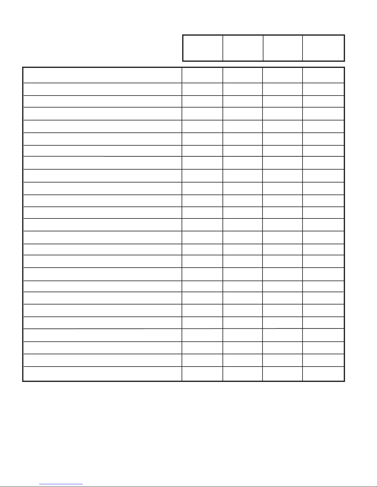
SPECIFICATIONS
Btu/hr 18,000 24,000 8,100 12,000
k.Cal./hr 4,536 6,048 2,041 3,024
E.E.R. - Btu/watt 8.5 8.5 9.5 9.0
E.E.R. - k.Ca./hr. 2.14 2.14 2.39 2.28
Volts 220/240 220/240 220/240 220/240
Amperes 10.2 13.5 3.9 6.5
Total Watts 2120 2825 850 1090
Fuse/Breaker Size (Amps) 15 20 15 15
Fan rpm-High 1200 1200 1300 970
Evaporator Air CFM 450 450 200 320
Evaporator Air M3/Hr 765 765 340 54
Dehumidication-Pts./hr. 5.7 8.5 2.5 3.0
Dehumidication-Lit./hr. 2.70 4.02 1.18 1.41
Width-Inches 25 15/16 25 15/16 19 3/4 25 15/16
Width-MM 659 659 502 659
Height-Inches 17 15/16 17 15/16 14 15 15/16
Height-MM. 456 456 356 405
Depth-Inches 27 3/8 27 3/8 21 3/4 27 3/8
Depth-MM 695 695 543 695
Min. Ext. Into Room-Inches 3 1/16 3 1/16 5 1/2 3 1/16
Min. Ext. Into Room-MM 78 78 140 78
Min. Ext to Outside-Inches 16 15/16 16 15/16 10 3/4 16 15/16
Min. Ext to Outside-MM 430 430 273 430
Shipping Weight-lbs. 150 160 84 122
Shipping Weight-kg 68.0 42.5 38.1 55.3
Page 4
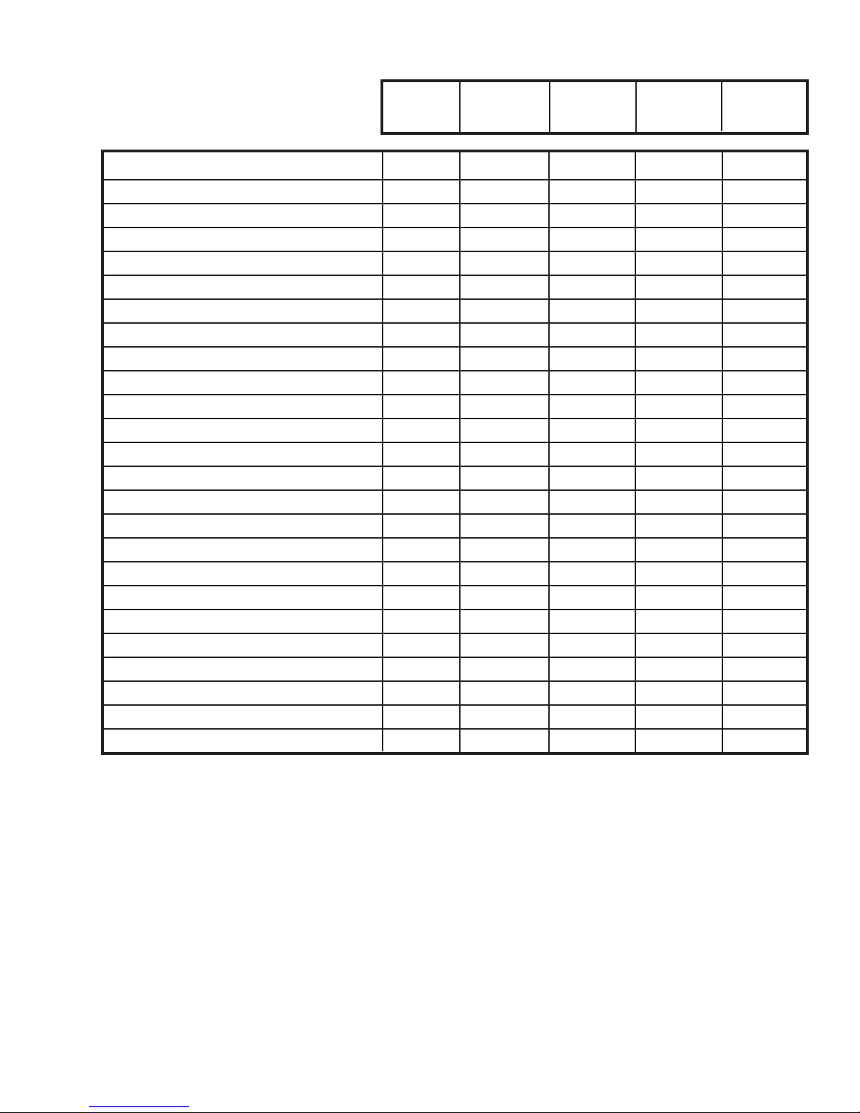
SPECIFICATIONS
YS12J50AA ES12J53AA EM18J53AB YM18J50AB EM24J53AB
Btu/Hr 12,000 12,000 18,000 18,000 24,000
k.Cal./hr 3,024 3,024 4,536 4,536 6,048
E.E.R. - Btu/watt 11.0 9.0 8.5 8.5 8.5
E.E.R. - k.Ca./hr. 2.77 2.28 2.14 2.14 2.14
Volts 220/240 220/240 220/240 220/240 220/240
Amperes 4.9 6.5 10.2 10.2 13.5
Total Watts 1090 1090 2120 2120 2825
Fuse/Breaker Size (Amps) 15 20 20 15 20
Fan rpm - High 970 970 1200 1200 1200
Evaporator Air CFM 320 320 450 450 450
Evaporator Air M3/hr. 544 544 765 765 765
Dehumidication - Pts./hr. 3.0 3.0 5.7 5.7 8.5
Dehumidication - Lit./hr. 1.41 1.41 2.70 2.70 4.02
Width - Inches 25 15/16 25 15/16 25 15/16 25 15/16 25 15/16
Width - MM 659 659 659 659 659
Height - Inches 15 15/16 15 15/16 17 15/16 17 15/16 17 15/16
Height - MM 405 405 456 456 456
Depth - Inches 27 3/4 27 3/8 27 3/8 27 3/8 27 3/8
Depth - MM 695 695 695 695 695
Min. Ext. into Room - Inches 3 1/16 3 1/16 3 1/16 3 1/16 3 1/16
Min. Ext. into Room - MM 78 78 78 78 78
Min. Ext to Outside - Inches 16 15/16 16 15/16 16 15/16 16 15/16 16 15/16
Min. Ext to Outside - MM 430 430 430 430 430
Shipping Weight - lbs. 122 121 150 170 160
Shipping Weight - kg 55.3 55.3 68.0 77.0 72.5
Page 5
Page 7
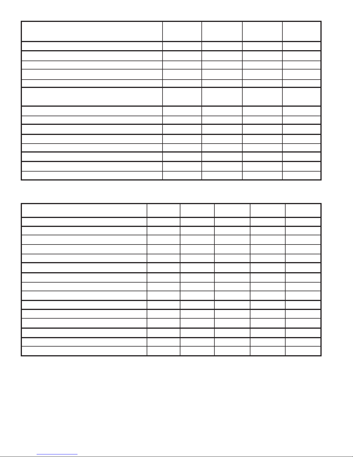
OPERATING DATA
OPERATING PRESSURES
Suction - PSI 78.0 72.0 68 80.0
Suction - ATM 5.3 4.89 4.62 5.44
Discharge - PSI 296 288 280 280
Discharge - ATM 20.14 19.60 19.05 19.04
ELECTRICAL RATING
(Compressor)
Amperes (FLA) 10.2 13.5 3.9 6.5
Locked Rotor Amps 52.0 78.0 20.0 32.0
REFRIGERANT, R-22
Charge in oz. 32.0 46.0 18.0 24.0
Charge in kg. 0,907 1,302 0,509 0,655
COMPRESSOR OIL
Charge in Fluid oz. 32 46 18 24
Charge in Liters 0,907 0,360 0,530 0,710
SM18J50BB SM24J50BB KQ08J50AB SS12J50AA
OPERATING DATA ES12J53AA YS12J50AA EM18J53AB YM18J50AB EM24J53AB
OPERATING PRESSURES
Suction PSI 76.5 76.5 78.0 75.5 72.0
Suction - ATM 5.20 5.20 5.3 5.14 4.89
Discharge - PSI 264 264 296 260 288
Discharge - atm 17.96 17.96 20.14 17.69 19.60
ELECTRICAL RATING
(Compressor)
Amperes (FLA) 5.2 4.9 10.2 8.4 13.5
Locked Rotor Amps 32.0 32.0 52.0 52.0 82.0
REFRIGERANT, R-22
Charge in Oz. 24.0 24.0 32.0 33.0 46.0
Charge in kg 0,670 0,670 0,907 0,907 1,302
COMPRESSOR OIL
Charge in Fluid Oz. 15.0 15.0 32.0 32.0 32.0
Charge in Liters 0,444 0,444 0,907 0,907 0,907
Page 6
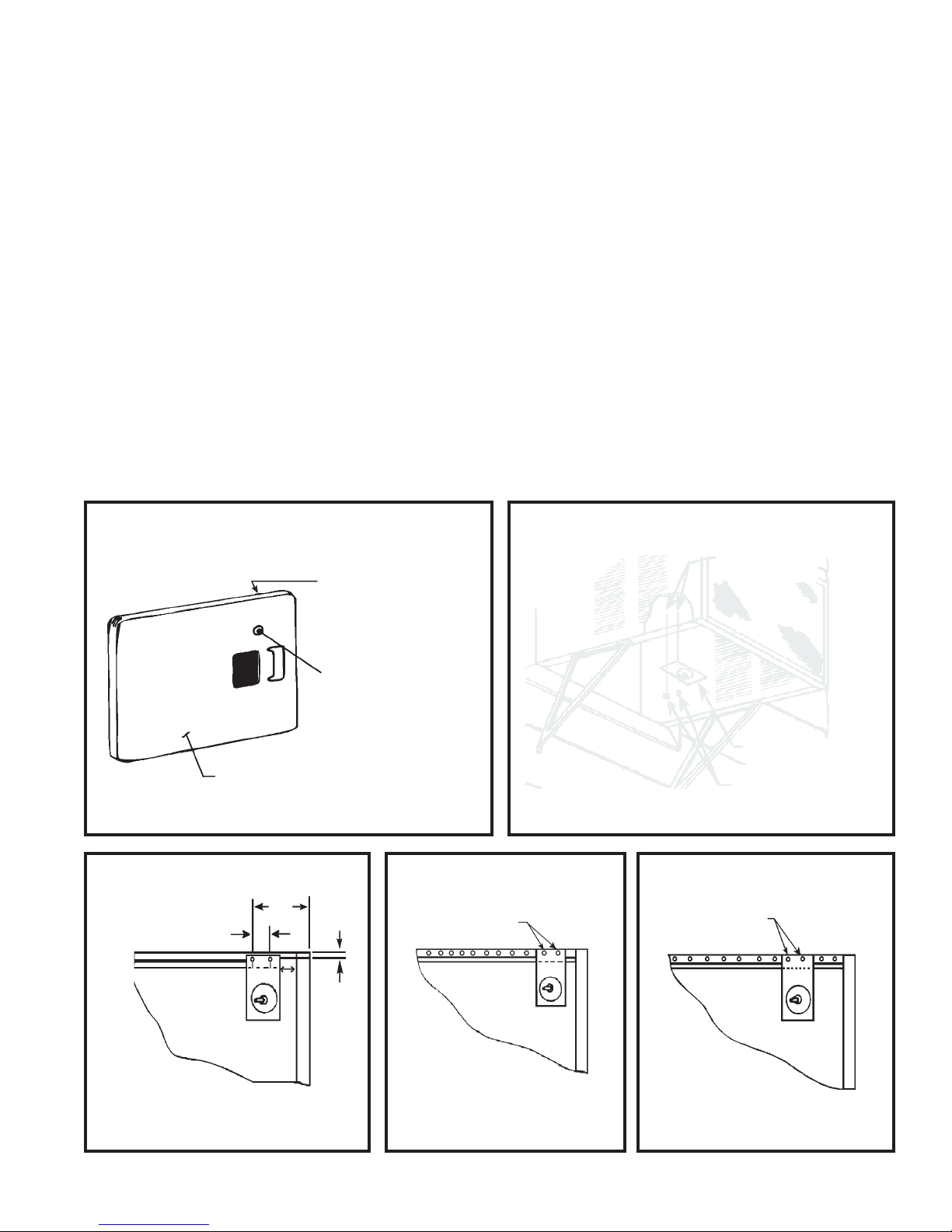
INSTALLATION INSTRUCTIONS FOR DC-2 DRAIN KIT
STEP 1 Before sliding the chassis into the outer shell, turn the chassis on its side and add a drain hole by drilling a
1/2" diameter hole as shown in Figure 1.
STEP 2 DC-2 mounts to the bottom of the outer shell as shown in Figure 2 on the right side as you face the unit. Use
two (2) 10-24 x 3/8" long machine screws and 10-24 hex nuts provided.
STEP 3 SQ, KQ, YQ Models - Drill two 1/4" holes in the outer shell as shown in Figure 3. Also drill a 3/8" diameter
hole in the base pan 3 1/2" from the back and 3 1/2" from the right side.
STEP 4 Small and Medium Chassis Models - Mount in the second and third holes from the rear of the shell. (See
Figure 4.)
STEP 5 Large Chassis Models - Mount in the third and fourth holes from the rear of the shell. (See Figure 5.)
STEP 6 Connect a suitable length of garden hose or other tubing to the end of the drain tube to drain the condensate
away.
FIGURE 1
FIGURE 3
RIGHT SIDE
APPROXIMATE
LOCATION OF EMBOSSMENT. DRILL
1/2 " DIA. HOLE.
BACK OF BASE PAN
6"
2"
3/8"
FIGURE 4
3rd AND 4th HOLES
FROM REAR OF
SHELL
FIGURE 2
10–24 x 3/8" LONG
SCREWS
DRAIN PLATE
10–24 NUTS
FIGURE 5
3rd AND 4th HOLES
FROM REAR OF
SHELL
"SQ," "KQ," "YQ" MODELS
BOTTOM VIEW
SMALL AND MEDIUM
CHASSIS MODELS
LARGE CHASSIS MODELS
BOTTOM VIEW
Page 7
Page 9
COMPONENT OPERATION AND TESTING
GROUND TEST
WARNING
DISCONNECT ELECTRICAL POWER
TO THE UNIT BEFORE SERVICING OR
TESTING
COMPRESSORS
Compressors are single phase, 220 or 220/240
volt, depending on the model unit. All compressor
motors are permanent split capacitor type, using
only a running capacitor across the start and run
terminal.
All compressors are internally spring mounted
and externally mounted on rubber isolators.
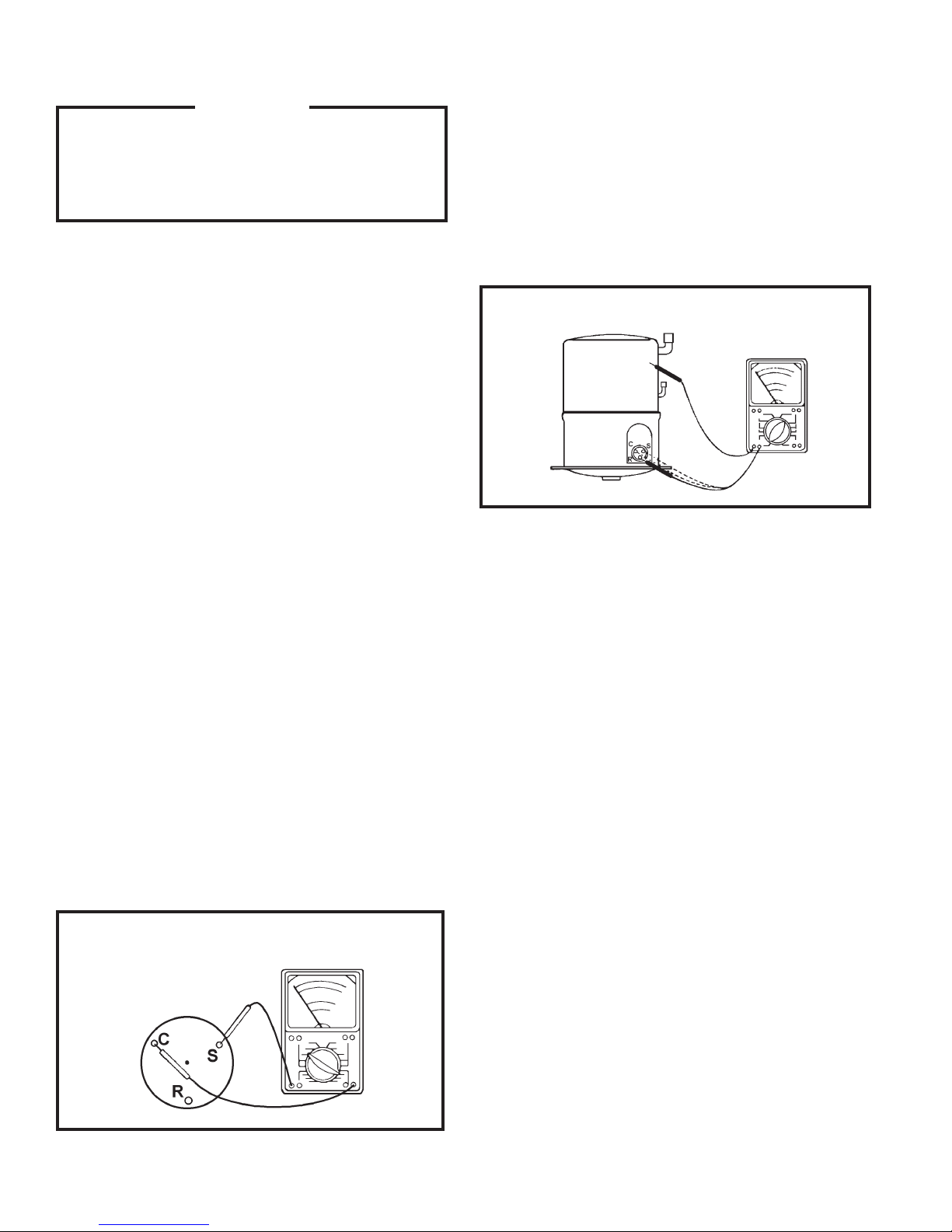
COMPRESSOR WINDING TEST
(See Figure 1.)
Remove the compressor terminal box cover
and disconnect the wires from the terminals.
Using an ohmmeter, check continuity across
the following:
Use an ohmmeter set on its highest scale. Touch
one lead to the compressor body (clean point
of contact, as a good connection is a must)
and the other probe in turn to each compressor
terminal. (See Figure 2.) If a reading is obtained,
the compressor is grounded and must be
replaced.
FIGURE 2 TYPICAL GROUND TEST
CHECKING COMPRESSOR EFFICIENCY
The reason for compressor inefficiency is
normally due to broken or damaged suction
and/or discharge valves, reducing the ability of
the compressor to pump refrigerant gas.
1. Terminal "C" and "S" - no continuity - open
winding - replace compressor.
2. Terminal "C" and "R" - no continuity - open
winding - replace compressor.
3. Terminal "R" and "S" - no continuity open
winding - replace compressor.
FIGURE 1 COMPRESSOR WINDING TEST
This condition can be checked as follows:
1. Install a piercing valve on the suction and
discharge or liquid process tube.
2. Attach gages to the high and low sides of the
system.
3. Start the system and run a "cooling or heating
performance test."
If test shows:
A. Below normal high side pressure.
B. Above normal low side pressure.
C. Low temperature difference across the coil.
The compressor valves are faulty - replace
the compressor.
Page 8
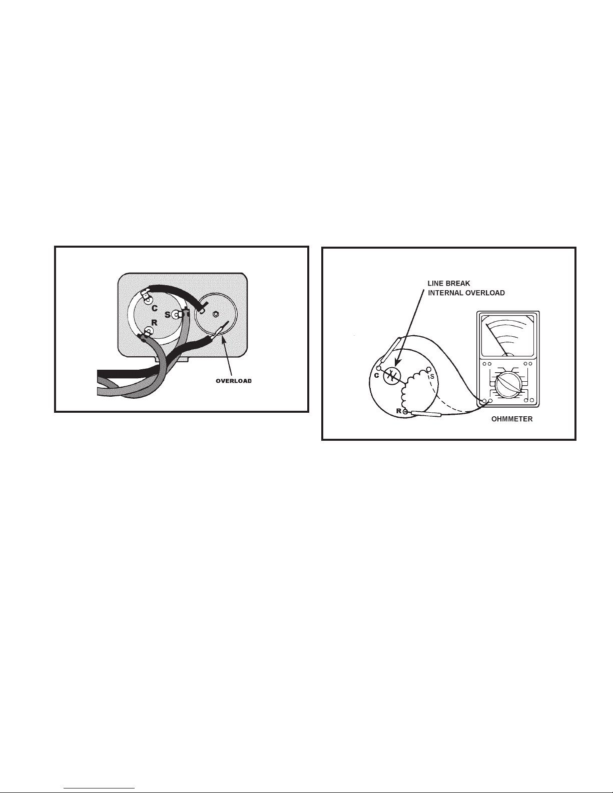
THERMAL OVERLOAD (External)
TERMINAL OVERLOAD (Internal)
Some compressors are equipped with an external
overload which is located in the compressor
terminal box adjacent to the compressor body.
(See Figure 3:) The overload is wired in series
with the common motor terminal. The overload
senses both motor amperage and compressor
temperature. H igh motor tempe rature or
amperage heats the disc causing it to open and
break the circuit to the common motor terminal.
FIGURE 3 EXTERNAL OVERLOAD
Some model compressors are equipped with an
internal overload. The overload is embedded
in the motor windings to sense the winding
temperature and/or current draw. The overload
is connected in series with the common motor
terminal. Should the internal temperature
and/or current draw become excessive, the
contacts in the overload will open, turning off
the compressor. The overload will automatically
reset, but may require several hours before the
heat is dissipated.
FIGURE 4 INTERNAL OVERLOAD
Heat generated within the compressor shell is
usually due to:
1. High amperage
2. Low refrigerant charge.
3. Frequent recycling.
4. Dirty Condenser.
TERMINAL OVERLOAD - TEST
(Compressor - External Type)
1. Remove overload.
2. Allow time for the overload to reset
before attempting to test.
3. Apply ohmmeter probes to the terminal
on the overload wires. There should be
continuity through the overload.
CHECKING INTERNAL OVERLOAD
(See Figure 4.)
1. With no power to the unit, remove the leads
from the compressor terminals.
2. Using an ohmmeter, test continuity between
terminals "C–S" and "C–R." If not continuous,
the compressor overload is open and the
compressor must be replaced.
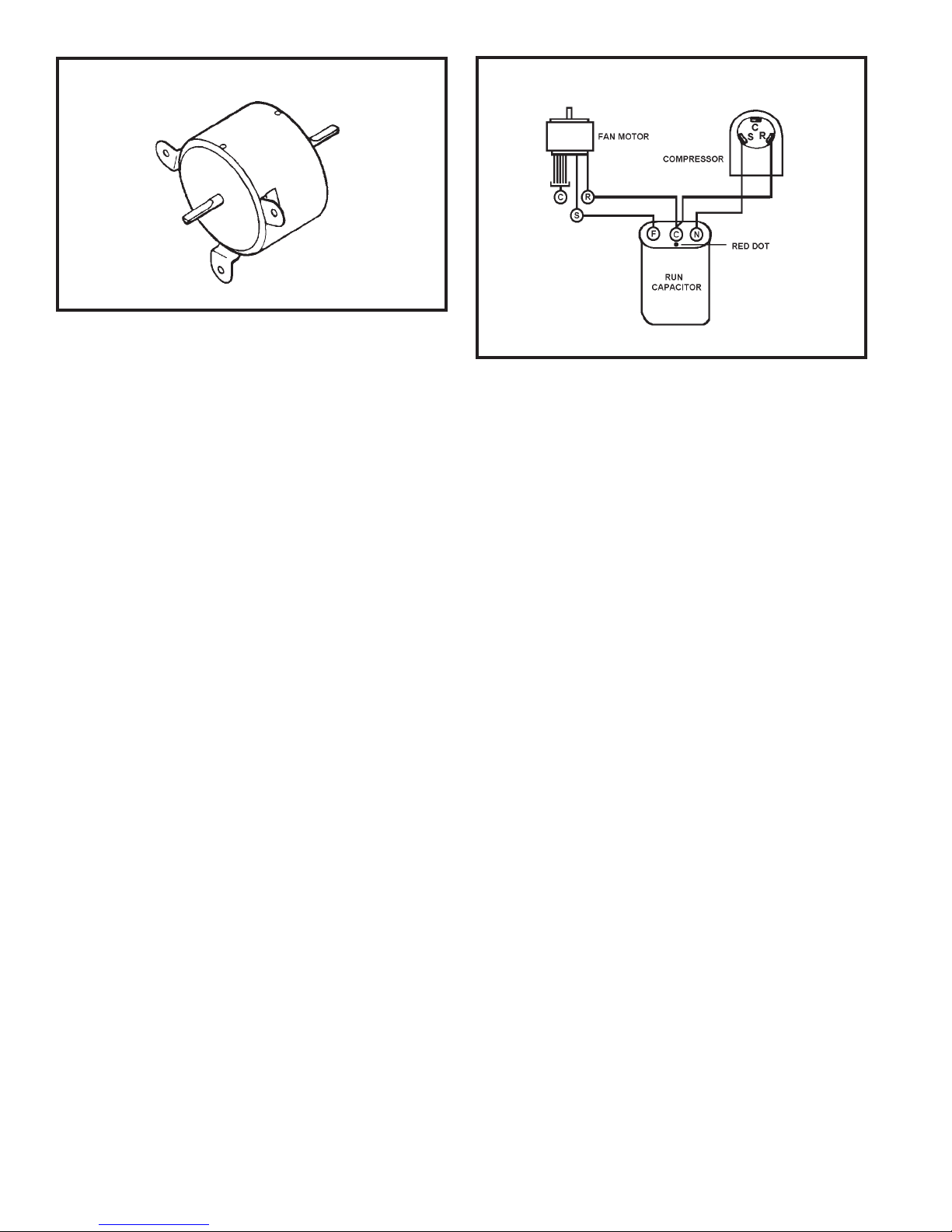
FAN MOTOR
A single phase permanent split capacitor motor is
used to drive the evaporator blower and condenser
fan. A self-resetting overload is located inside the
motor to protect against high temperature and
high amperage conditions.
Page 9
Page 11
FIGURE 5 FAN MOTOR
FAN MOTOR-TEST
FIGURE 6 RUN CAPACITOR HOOK–UP
1. Determine that the capacitor is serviceable.
2. Disconnect the fan motor wires from the fan
speed switch or system switch.
3. Apply "live" test cord probes on the black wire
and the common terminal of the capacitor.
Motor should run at high speed.
4. Apply "live" test cord probes on the red wire
and common terminal of the capacitor. Motor
should run at low speed.
5. Apply "live" test cord probes on each of the
remaining wires from the speed switch or
system switch to test intermediate speeds.
RUN CAPACITOR
A run capacitor is wired across the auxiliary and
main winding of a single phase permanent split
capacitor motor such as the compressor and fan
motors. A single capacitor can be used for each
motor or a dual rated capacitor can be used for
both.
The capacitor’s primary function is to reduce the
line current while greatly improving the torque
characteristics of a motor. The capacitor also
reduces the line current to the motor by improving
the power factor of the load. The line side of the
capacitor is marked with a red dot and is wired to
the line side of the circuit. (See Figure 6.)
CAPACITOR – TEST
1. Remove the capacitor from the unit.
2. Check for visual damage such as bulges,
cracks, or leaks.
3. For dual rated capacitors, apply an ohmmeter
lead to the common (C) terminal and the other
probe to the compressor (HERM) terminal. A
satisfactory capacitor will cause a deection
on the pointer, then gradually move back to
innity.
4. R everse th e leads of t he probe a nd
momentarily touch the capacitor terminals.
The deection of the pointer should be two
times that of the rst check if the capacitor is
good.
5. Repeat steps 3 and 4 to check the fan motor
capacitor.
NOTE: A shorted capacitor will indicate a low
resistance and the pointer will move more to the
"0" end of the scale and remain there as long as
the probes are connected. An open capacitor will
show no movement of the pointer when placed
across the terminals of the capacitor.
Page 10
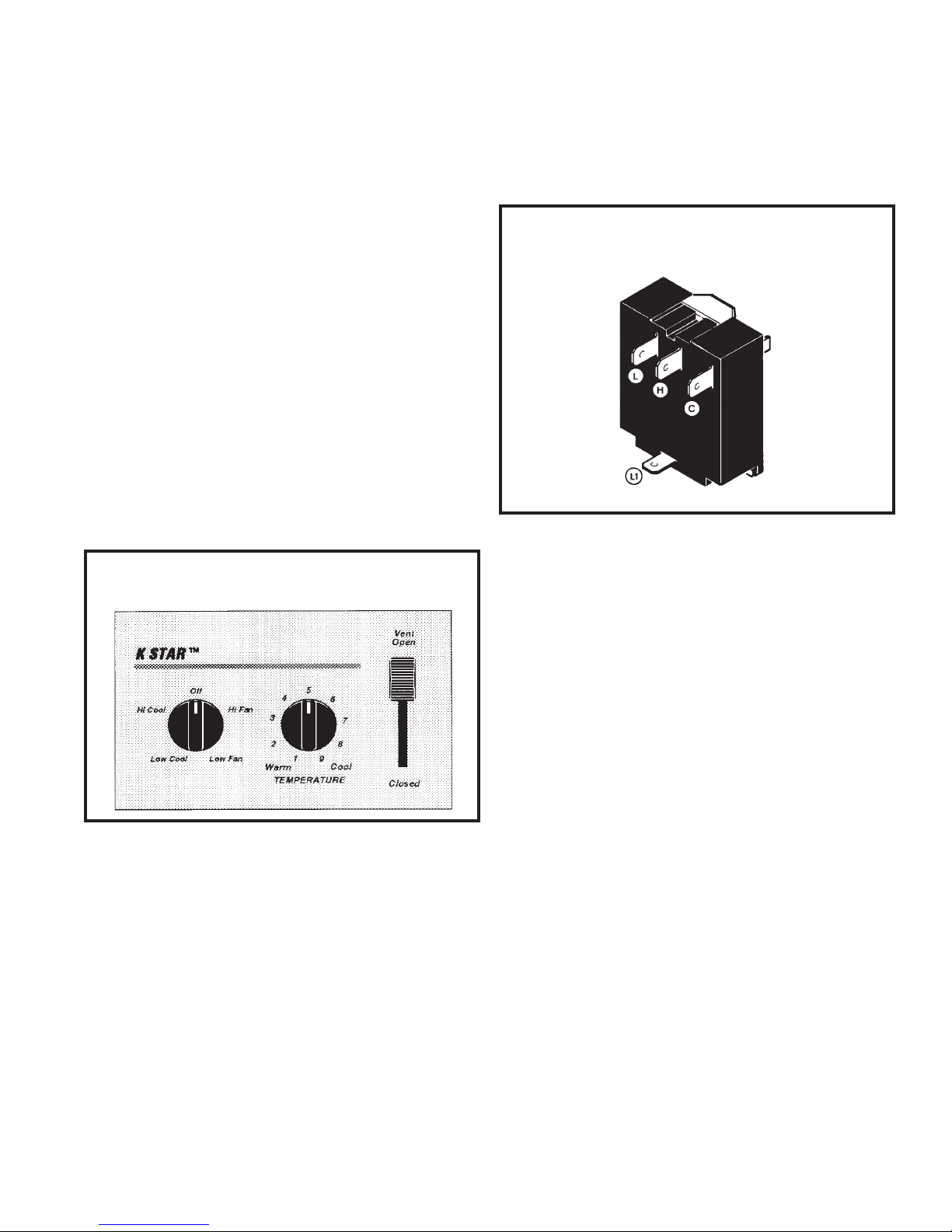
SYSTEM CONTROL SWITCH
("KQ" Models Only - Figure 7)
3. "Low Cool" Position -0 between terminals "L1"
and "L" and "C."
The KQ model unit uses a ve position control
switch to regulate the operation of the unit. The
function of each position (clockwise rotation) is
as follows:
1. "Off" - Turns everything off.
2. "Hi Fan" - Maximum circulation of ltered room
air (no cooling).
3. "Low Fan" - Fan runs slower for less circulation
of ltered room air.
4. "Low Cool" - Fan runs slow for quiet operation
when maximum cooling is not needed.
5. "Hi Cool" - Highest fan speed for maximum
cooling.
FIGURE 7 SYSTEM CONTROL PANEL
4. "Hi Cool" Position - between terminals "L1"
and "H" and "CC."
FIGURE 8 SYSTEM CONTROL SWITCH
SYSTEM CONTROL SWITCH
("SS," "SM" & "SL" Models)
("KQ" Models Only)
SYSTEM CONTROL SWITCH - TEST
Part No. 604-416-06 (See Figure 8)
Turn knob to phase of switch being tested. There
must be continuity as follows:
1. "Hi Fan" Position - between terminals "L1"
and "H."
2. "Low Fan" Position - between terminals "L1"
and "L."
A ve position control switch is used to regulate
the operation of the fan motor and compressor.
The compressor can be operated with the fan
operating at low, medium or high speed. The
fan motor can also be operated independently on
medium speed. See Switch Section as indicated
on decorative control panel. (See Figure 9.)
SYSTEM CONTROL SWITCH - TEST
Disconnect leads from the control switch. (See
Figure 10.) There must be continuity as follows:
1. "Off " Posit ion - no continuit y between
terminals.
2. "Low Cool" Position - between terminals "L1"
and "C," "LO" and "MS."
3. "Med Cool" Position - between terminals "L1"
and "C," "M" and "MS."
Page 11

Page 13
FIGURE 9 SYSTEM CONTROL PANEL
("SS" & "SM" Models Only)
FIGURE 11 SYSTEM CONTROL PANEL
(Heat Pump & Electric Heat Models)
4. "Hi Cool" Position - between terminals "L1"
and "C," "H" and "MS."
5. "Fan Only" Position - between terminals "L1"
and "2."
SYSTEM CONTROL SWITCH
(Heat Pump & Electric Heat Models)
An eight position control switch is used to regulate
the operation of the fan motor and compressor.
The compressor can be operated with the fan
operating at low, medium or high speed in the
cooling or heating mode. The fan motor can also
be operated independently on medium speed.
See Switch Section as indicated on the decorative
control panel. (See Figure 11.)
1. "Off" Position - Everything is off.
speed, compressor or electric heater is on.
6. "Med Heat" Position - fan operates on medium
speed, compressor or electric heater is on.
7. "Lo Heat" Position - Fan operates on low
speed, compressor or electric heater is on.
8. "Fan Only" Position - Fan operates on medium
speed.
FIGURE 10 SYSTEM CONTROL SWITCH
("SS" & "SM" Models Only)
2. "Low Cool" Position - Fan operates on low
speed, compressor is on.
3. "Med Cool" Position - Fan operates on medium
speed, compressor is on.
4. "Hi Cool" Position - Fan operates on high
speed, compressor is on.
5. "Hi Heat" Position - Fan operates on high
Page 12
NOTE: Heat pump models with electric
heat - in the heat position, the heating
element will be energized only when
the outdoor temperature is below the
operating range of the heat pump.
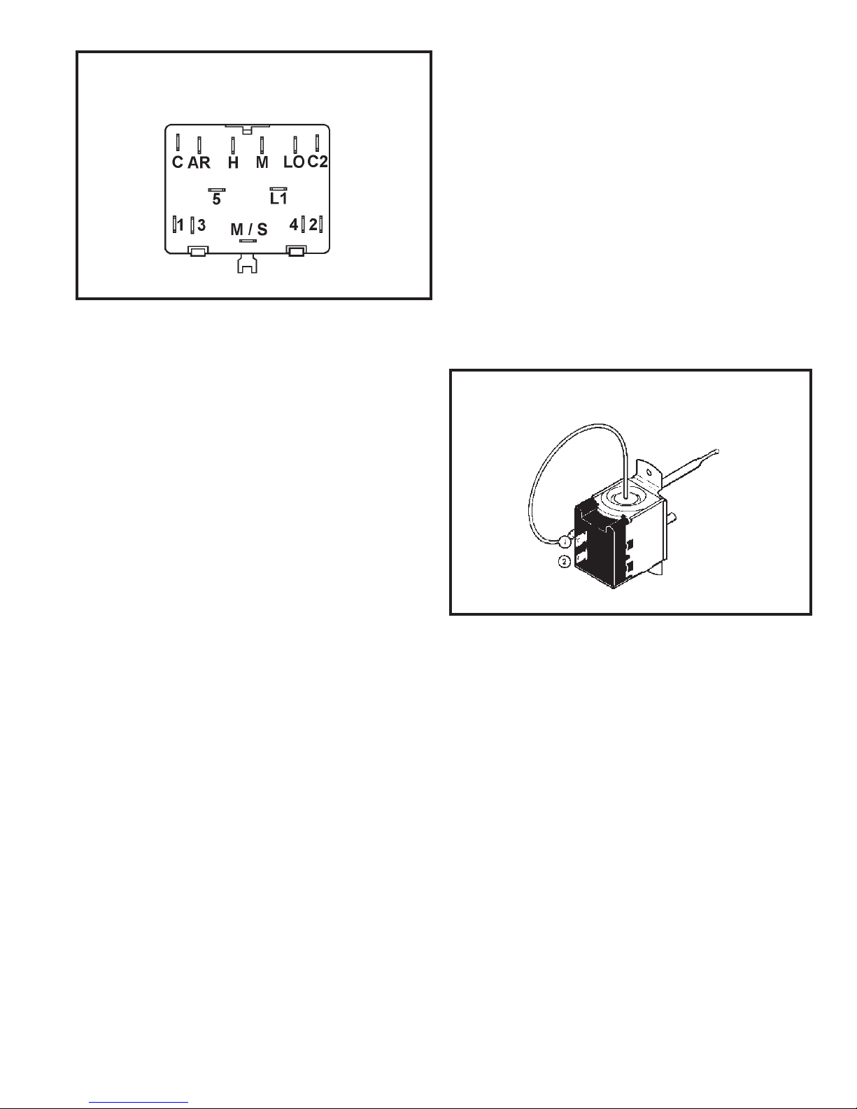
FIGURE 12 SYSTEM CONTROL SWITCH
(Heat Pump & Electric Heat Models)
SYSTEM CONTROL SWITCH - TEST
Disconnect the leads from the control switch.
Turn the control to the position being tested.
(See Figure 12). There must be continuity as
follows:
THERMOSTAT
("KQ" Models) - (See Figure 13)
The thermostat (part number 613-503-10) is
used to cycle the compressor on, and maintain
the temperature at the comfort level desired. The
thermostat has a range from 63o ± 2o F to 90o ±
4o F, with a differential of 5o F. Turning the knob
clockwise, lowers the indoor room temperature
setting, while turning the knob counterclockwise
raises the indoor temperature.
FIGURE 13 THERMOSTAT ("KQ" Models Only)
1. " Off " Posit ion - no con tinuity bet ween
terminals.
2. "Low Cool" Position - between terminals "C"
and "3," "C2" and "2," "LO" and "M/S," "AR"
and "5."
3. "Med Cool" Position - between terminals "C"
and "3," "C2" and "2," "M" and "M/S," "AR" and
"5."
4. "Hi Cool" Position - Between terminals "C"
and "3", "C2" and "2," "H" and "M/S," "AR
and "5."
5. "Hi Heat" Position - between terminals "C" and
"1", "C2" and "4," "H" and "M/S," "AR" and
"5."
6. "Med Heat" Position - between terminals "C"
and "1," "C2" and "4," "M" and "M/S," "AR" and
"5."
7. "Lo Cool" Position - between terminals "C" and
"1," "C2" and "4," "LO" and "M/S," "AR" and
"5."
TEST:
Remove the wires, turn the thermostat to its
coldest position. Check for continuity between
the two terminals. Turn the thermostat to its
warmest position, check continuity to see of the
contacts open. NOTE: The temperature must be
in the range listed to check the thermostat.
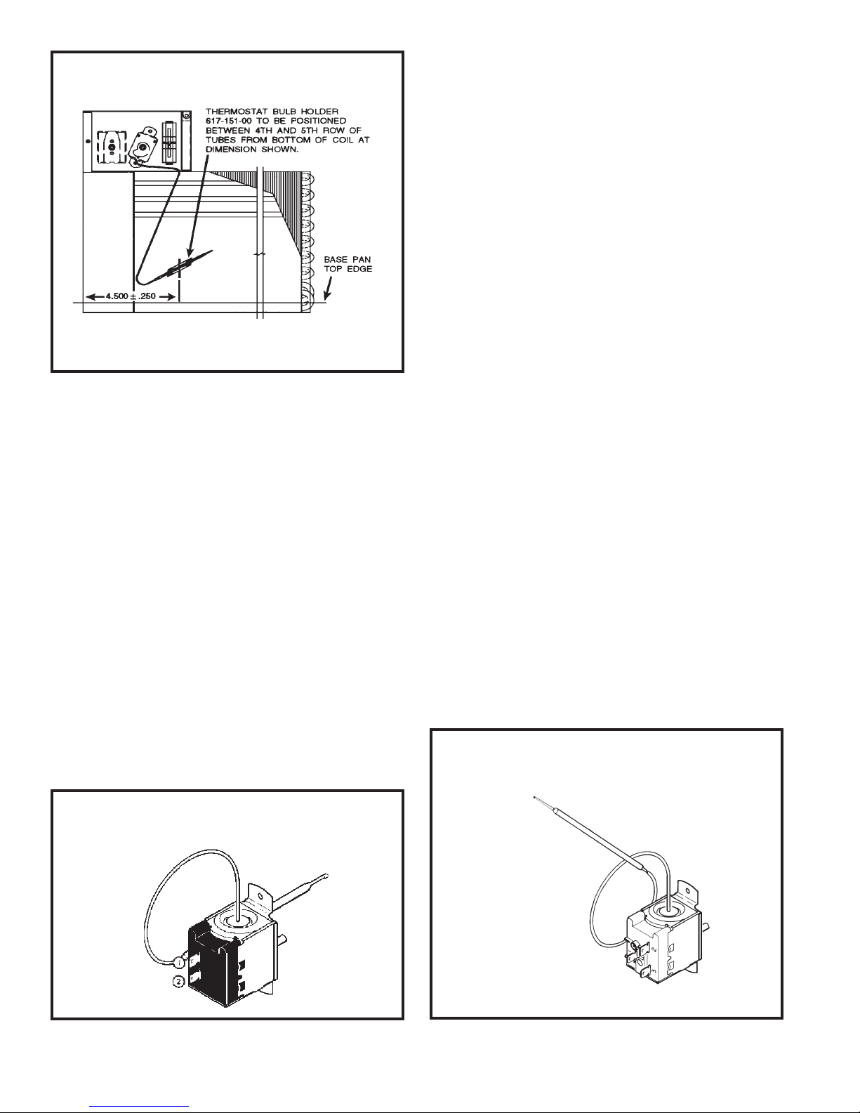
THERMOSTAT BULB LOCATION
("KQ" Models) - (See Figure 14)
The position of the bulb is important in order for
the thermostat to function properly. (See Figure
14.) The bulb of the thermostat should be located
approximately 45o to a maximum of 60o from
horizontal. Also, do not allow the thermostat bulb
to touch the evaporator coil.
8. "Fan Only" Position - between terminals "L1"
and "M."
Page 13
Page 15
FIGURE 14 THERMOSTAT BULB LOCATION
("KQ" Models Only)
THERMOSTAT
("SS" & "SM" Models) - (Figure 15)
A cross ambient thermostat is used on all standard
chassis units. In addition to cycling the unit in
a heating or cooling operation, the thermostat
will terminate the cooling cycle in the event ice
forms on the evaporator coil. In this case the
thermostat functions as a de-icing control. A
resistor (anticipator) is positioned within a plastic
block to supply a small amount of heat to the bulb
area to prevent long "off cycles" in the "Cool-Fan
Auto" (MoneySaver) position. (See Figure 15.) A
current feedback through the fan motor windings
during "off cycle" periods completes the circuit to
the resistor.
TEST
Remove the wires from the thermostat. Turn the
thermostat to its coldest position. Check to see
if there is continuity between the two terminals.
Turn the thermostat to its warmest position.
Check continuity to see of the thermostat contacts
open. Note: The temperature must be within
the range listed to check the thermostat. Refer
to the troubleshooting section in this manual for
additional information on thermostat testing.
THERMOSTAT ADJUSTMENT
("SS" & "SM" Models)
No attempt should be made to adjust the
thermostat. Due to the sensitivity of the internal
mechanism and the sophisticated equipment
required to check the calibration, it is suggested
that the thermostat be replaced rather than
calibrated.
THERMOSTAT - (FIGURE 16)
(Heat Pump & Electric Heat Models Only)
A cross ambient thermostat is used on all heat
pump and electric heat units. In addition to
cycling the unit in a heating or cooling operation,
the thermostat will terminate the cooling cycle
in the event ice forms on the evaporator coil, in
this case the thermostat functions as a de-ice
control.
RANGE: Cooling Model Thermostat
o
60o F ( ± 2
FIGURE 15 THERMOSTAT
("SS" & "SM" Models Only)
Page 14
) to 92o F( ±4o )
FIGURE 16 THERMOSTAT
(Heat Pump & Electric Heat Models)
618-224-00
A resistor (anticipator) is positioned within a
plastic block to supply a small amount of heat
to the bulb area to prevent long "off cycles" in
the "Cool-Fan Auto" (MoneySaver) position.
(See Figure 16.) A current feedback through
the fan motor windings during "off" cycle periods
completes the circuit to the resistor.
In the heating cycle, the heat anticipator is
energized to supply a small amount of heat during
the "on" cycle. This will open the contacts in
the thermostat prematurely to maintain a closer
differential between the "cut-in" and "cut-out"
temperature. The heat anticipator is energized
in the heating mode regardless if the fan is placed
in the automatic (MoneySaver) or constant run
position.
RANGE: Cooling Model Thermostat
60o F ( ± 2o ) to 92o F( ±4o )
RESISTOR (See Figure 17)
(Heat Anticipator)
Failure of the resistor will cause prolonged "off"
and "on" cycles of the unit. When replacing a
resistor, be sure and use the exact replacement.
Resistor ratings are as follows:
115 Volt --5,000 ohms 3 watt
230 Volt-- 20,000 ohms 3 watt
FIGURE 17 RESISTOR
TEST
Cooling/Heating Models: Remove the wires from
the thermostat and check continuity between
terminal "2" (common) and "3" for cooling.
Check between terminals "2" (common) and
"1" for heating. Also check that contacts in the
thermostat open after being placed in either
position. NOTE: The temperature must be within
the range listed to check the thermostat. Refer
to the troubleshooting section in this manual for
additional information on thermostat testing.
THERMOSTAT ADJUSTMENT
(Heat Pump & Electric Heat Models Only)
No attempt should be made to adjust the
thermostat. Due to the sensitivity of the internal
mechanism and the sophisticated equipment
required to check the calibration, it is suggested
that the thermostat be replaced rather than
calibrated. The thermostat bulb must be straight
to insure proper performance.
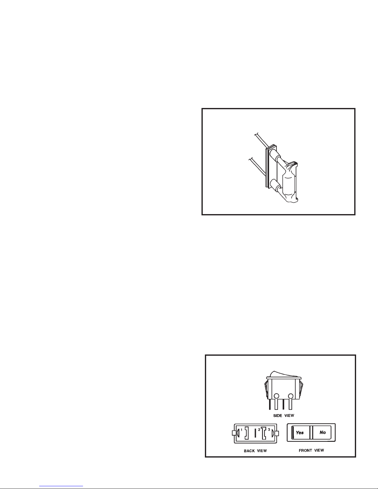
MONEYSAVER® SWITCH
(Rocker Switch) - (See Figure 18)
This rocker switch can be depressed to either
YES or NO. In the YES position you will get
the most economical operation. Both the fan
and compressor will cycle on and off together,
maintaining the selected temperature at a more
constant level and reducing the humidity more
efciently in the cooling mode. This control will
only operate when the unit is in a cooling or
heating mode. In the NO position, the fan will
run constantly as long as the unit is in the cooling
or heating mode.
FIGURE 18 ROCKER SWITCH
Page 15
Page 17
TEST:
Disconnect the leads from the switch. Depress
the switch to the function being tested.
1. When YES is selected, there should be
continuity between terminals "1" and "2."
2. When NO is selected, there should be
continuity between terminals "2" and "3."
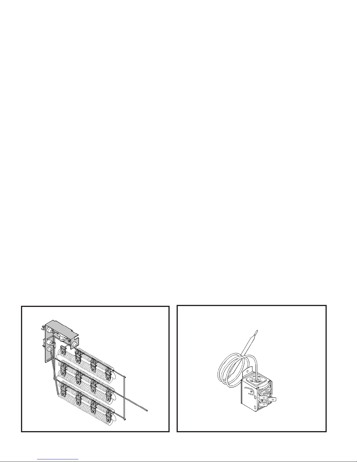
HEATING ELEMENT - (See Figure 19)
The control is designed to open at 110°F ± 6°F.
Test continuity below 110°F and for open above
110°F.
The heating element for the "Y" model is energized
by an outdoor thermostat. The outdoor thermostat
is adjusted at a predetermined temperature to
bring on the heating element and turn off the
compressor. The room thermostat will then
control the cycling of the element when the
selected indoor temperature is reached.
All electric heat models are equipped with a 3.3
KW heating element.
The heating element contains a fuse link and a
heater limit switch. The fuse link is in series with
the power supply and will open and interrupt the
power when the temperature reaches 161.6°F,
or a short circuit occurs in the heating element.
Once the fuse link separates, a new fuse link
must be installed. NOTE: Always replace with
the exact replacement.
The heater element has a high limit control. This
control is a bimetal thermostat mounted in the top
of the heating element.
Should the fan motor fail or lter become clogged,
the high limit control will open and interrupt
power to the heater before reaching an unsafe
temperature condition.
Testing of the elements can be made with
an ohmmeter across the terminals after the
connecting wires have been removed. A cold
resistance reading of approximately 14.5 ohms
for the 3.3 KW heater, should be registered.
DEFROST THERMOSTAT
(Heat Pump Models Only)
This thermostat (Figure 20) is single pole-double
throw with contacts between terminals "2" and "3"
closing on temperature rise and contact between
terminals "2" and "1" closing on temperature
fall.
This control is a dual purpose control that acts as
an outdoor thermostat and defrost control.
When the sensing bulb, attached to the condenser
FIGURE 19 HEATING ELEMENT
Page 16
FIGURE 20 DEFROST THERMOSTAT
(Heat Pump Models)
613-503-13
coil, senses enough icing on the outdoor coil, it
will interrupt power to the compressor until the
coil temperature reaches above 43 degrees, then
the unit will resume operating in the reverse cycle
mode.
The fan motor will not turn off when defrost occurs,
and the 4-way valve will not reverse.
DEFROST BULB LOCATION
(Heat Pump Models Only)
1. Disconnect power to the unit.
2. Disconnect the coil leads.
3. Attach the probes of an ohmmeter to each coil
lead and check for continuity.
WARNING: Do not start the unit with the solenoid
coil removed from the valve, or do not remove the
coil after the unit is in operation. This will cause
the coil to burn out.
The defrost control bulb must be mounted
securely and in the correct location to operate
properly (See Figure 21).
SOLENOID COIL
(Heat Pump Models Only)
The solenoid coil is an electromagnetic type coil
mounted on the reversing valve and is energized
during the operation of the compressor in the
heating cycle.
Should the reversing valve fail to shift during the
heating cycle, test the solenoid coil. Also, refer
to the Touch Test Chart on Page 25.
TO TEST:
FIGURE 21 DEFROST THERMOSTAT
BULB LOCATION
(All Heat Pump Models)
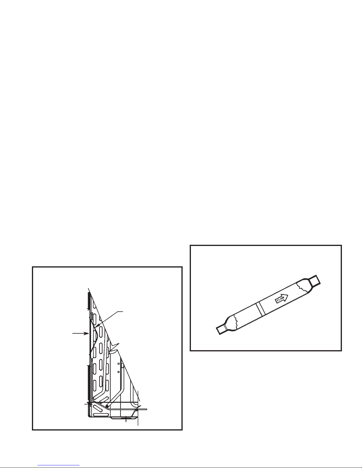
CHECK VALVE - (Figure 22)
(Heat Pump Models Only)
A one-way check valve is installed in the capillary
tube circuit to allow the ow of refrigerant through
both tubes in the evaporator during the cooling
mode.
In the heating mode, one capillary is closed by
the check valve to allow ow through one capillary
only to the condenser.
FIGURE 22 ONE–WAY CHECK VALVE
(Heat Pump Models)
SLIDE BULB
END OF THERMOSTAT DEFROST UNDER
RETAINER AS
SHOWN
RETAINER
618-244-00
NOTE: The slide (check) inside the valve is made
of teon. Should it become necessary to replace
the check valve, place a wet cloth around the
valve to prevent overheating during the brazing
operation. The ow arrow on the valve must point
towards the evaporator.
Page 17
 Loading...