

INSTALLATION
&
OPERATION
[_l,,IoHiI._.,5iIo][_]
WallMaster _Packaged Terminal
Air Conditioners
Packaged Terminal Heat Pumps
• Standard Unit
• Seacoast Protected Unit
• Remote Thermostat Unit
• Central Desk Control Unit
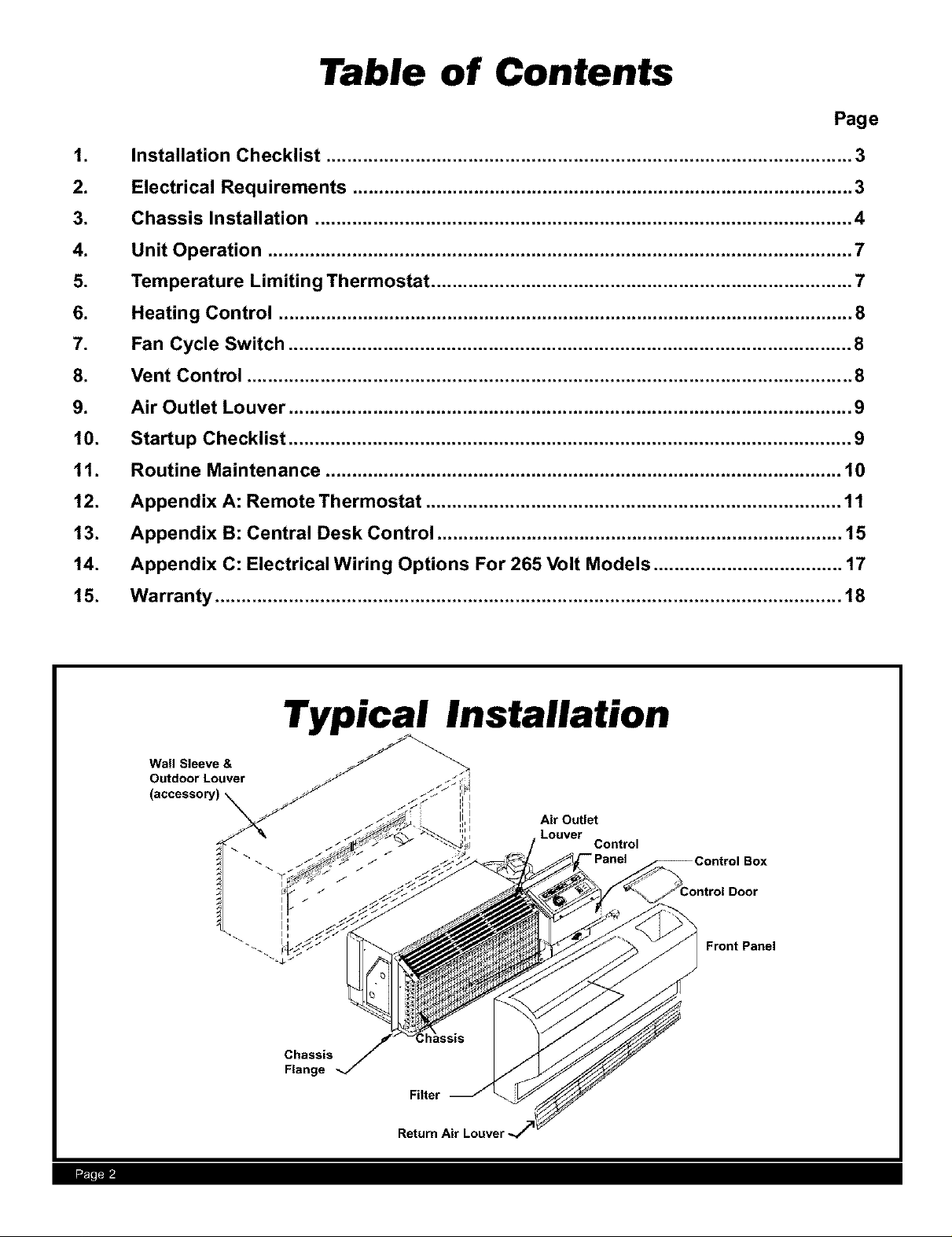
Table of Contents
Page
.
Installation Checklist .................................................................................................... 3
2.
3.
4.
9.
10.
11.
12.
13.
14.
15.
Electrical Requirements ............................................................................................... 3
Chassis Installation ...................................................................................................... 4
Unit Operation ............................................................................................................... 7
Temperature Limiting Thermostat ................................................................................ 7
.
Heating Control ............................................................................................................. 8
Fan Cycle Switch ........................................................................................................... 8
.
Vent Control ................................................................................................................... 8
Air Outlet Louver ........................................................................................................... 9
Startup Checklist ........................................................................................................... 9
Routine Maintenance .................................................................................................. 10
Appendix A: Remote Thermostat ............................................................................... 11
Appendix B: Central Desk Control ............................................................................. 15
Appendix C: Electrical Wiring Options For 265 Volt Models .................................... 17
Warranty ....................................................................................................................... 18
.... il
Typical Installation
Air Outlet
Louver
Chassis
Flange
Filter
Return Air Louver-
Control
Box
Front Panel
Installation
Checklist Electric shock hazard.
Turn off electric power before service or installaSor
All electrical connections and circuits are installed in compli-
ance with and conform to the National Electrical Code and lo-
cal codes which have jurisdiction.
_/ Wall sleeve and condensate lines are installed correctly.
_/ Electrical power is disconnected.
_/ Condenser air inlet and outlet MUST be clear and free of obstructions.
_/ Cardboard wall sleeve support and louver weatherboard are removed.
_/ Wall sleeve foam gasket is installed (if applicable).
_/ Subbase kit or other means of structural support is required for ALL installations which project more than 8"
into room.
_/ Unit is installed in a 16"H x42"Wx 11 1/2"D wall sleeve. A sleeve baffle kit is used when installed in a sleeve
greater than 11 1/2" deep.
Read these instructions carefully and completely
before attempting installation. Unit should be
installed by qualified service personnel ONLY.
Failure to do so can result in property damage,
personal injury and/or death.
_/ Ensure that drapes, bed, bedspread, furniture, etc. DO NOT block either return or discharge air louvers.
_/ Condensate Drain Kits should be installed for complete condensate removal.
Electrical
Electric shock hazard.
Turn OFF electric power before service or installation.
All electrical connections and wiring MUST be installed
by a qualified electrician and conform to the National
Electrical Code and all local codes which have juris-
diction.
Failure to do so can result in property damage, per-
sonal injury and/or death.
Wire Size
Fuse/Circuit
Breaker
Grounding
Receptacle
Requirements
Use ONLY wiring size recommended for single out-
let branch circuit.
Use ONLY type and size fuse or HACR circuit
breaker.
Indicated on unit's rating plate (see page 4). Proper current protection to the unit is the responsibility of
the owner. NOTE: A time delay fuse is provided with 265V units.
Unit MUST be grounded from branch circuit through service cord to unit, or through separate ground
wire provided on permanently connected units. Be sure that branch circuit or general purpose outlet is
grounded.
The field supplied outlet must match plug on service cord and be within reach of service cord. Refer to
Table 1 for proper receptacle and fuse type. Do NOT alter the service cord or plug. Do NOT use an
extension cord.
Wire Sizing
Use recommended wire size given in Table 2 and install a single branch circuit. All wiring must comply
with local and national codes. NOTE: Use copper conductors only.
rl'l
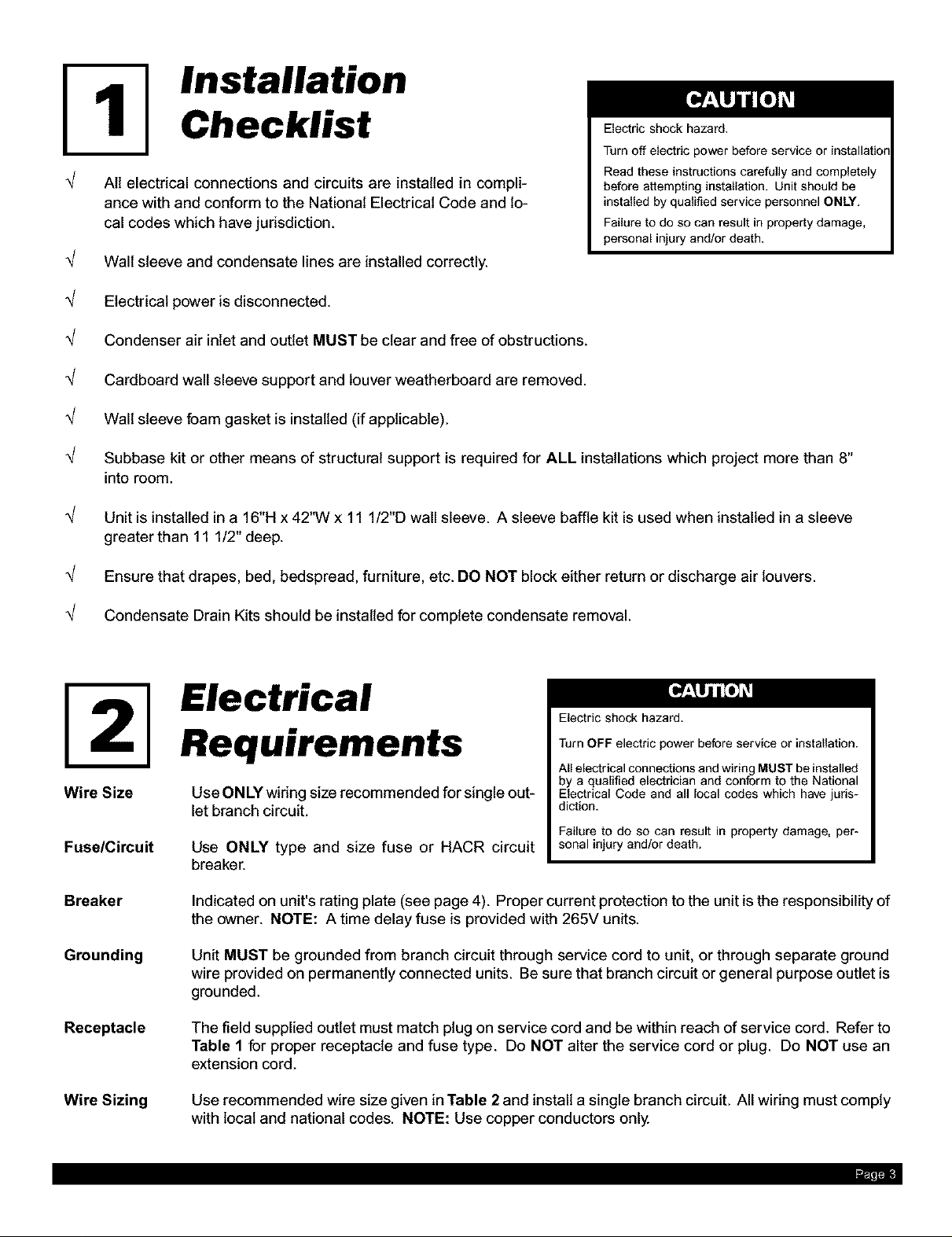
Electrical Rating Tables
All 230/208 volt units are equipped with power cords.
See Appendix C on page 17 for wiring instructions on 265V units.
I NOTE: Use Copper Conductors ONLY. I
Wire sizes are per NEC. Check local codes
for overseas applications.
Table 2
Recommended branch circuit wire sizes*
Table1
AMPS
RECEPTACLE
MANUFACTURER
Hubbell
P&S
GE
Arrow-Hart
TIME-DELAY TYPE
FUSE 30
(or HACR circuitbreaker)
HACR -- Heating, Air conditioning, Refrigeration
* May be used for 15 Amp applications if fused for 15 Amp
NOTE: 265 volt units are permanently connected.
250 V Receptacles and Fuse Types
15 20 *
@
PART NUMBERS
5661 5461
5661 5871
GE4069-1 GE4182-1
5661 5861
15 20
30
9330
5930
GE4139-3
5700
Nameplate
maximum circuit
breaker size
15
20
30
AWG --American Wire Gauge
* Single circuit from main box
** Based on copper wire, single insulated
conductor at 60°C
AWG Wire size**
14
12
10
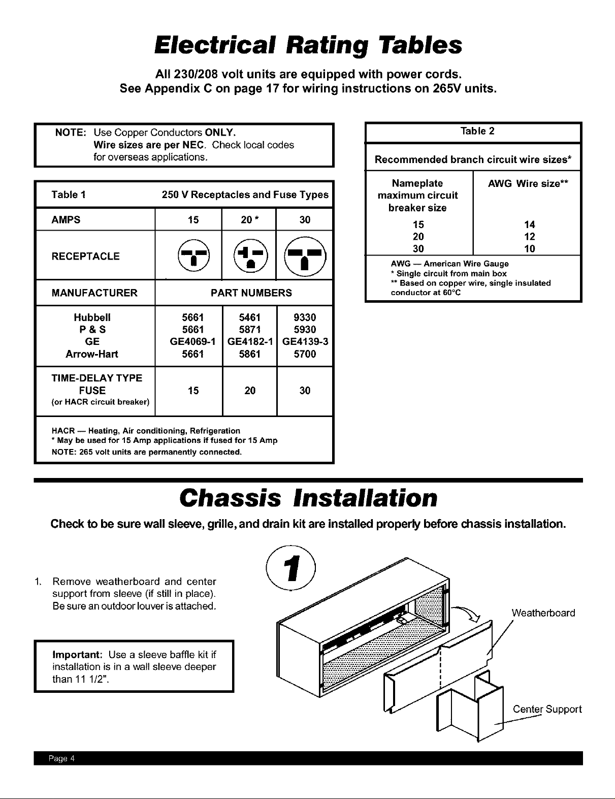
Chassis Installation
Check to be sure wall sleeve, grille, and drain kit are installed properly before chassis installation.
Remove weatherboard and center
support from sleeve (if still in place).
Be sure an outdoor louver is attached.
Important: Use a sleeve baffle kit if
installation is in a walt sleeve deeper
I
than 11 1/2".
.... ?1'11
Weatherboard
Center Support
Suffocation hazard.
Keep bag away from babies and children.
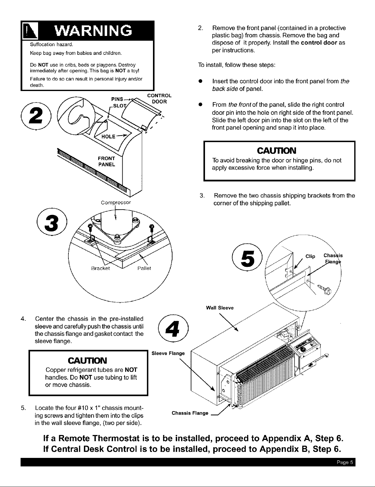
2,
Remove the front panel (contained in a protective
plastic bag) from chassis. Remove the bag and
dispose of it properly. Install the control door as
per instructions.
Do NOT use in cribs, beds or playpens, Destroy
immediately after opening. This bag is NOT a toy!
Failure to do so can result in personal injury and/or
death.
PIN'( DOOR
Com#reseor
To install,follow these steps:
• Insert the control door into the front panel from the
back side of panel.
CONTROL
From the frontofthe panel, slide the right control
door pin into the hole on right side of the front panel.
Slide the left door pin into the slot on the left of the
front panel opening and snap it into place.
CAUTION
To avoid breaking the door or hinge pins, do not
apply excessive force when installing.
3. Remove the two chassis shipping brackets from the
corner of the shipping pallet.
4.
Center the chassis in the pre-installed
sleeve and carefully push the chassis until
the chassis flange and gasket contact the
sleeve flange.
CAUTION
Copper refrigerant tubes are NOT
handles. Do NOT use tubing to lift
or move chassis.
. Locate the four #10 x 1" chassis mount-
ing screws and tighten them into the clips
in the wall sleeve flange, (two per side).
If a Remote Thermostat is to be installed, proceed to Appendix A, Step 6.
If Central Desk Control is to be installed, proceed to Appendix B, Step 6.
®
Wall Sleeve
Sleeve Flange
\
Chassis Flange
rl'T
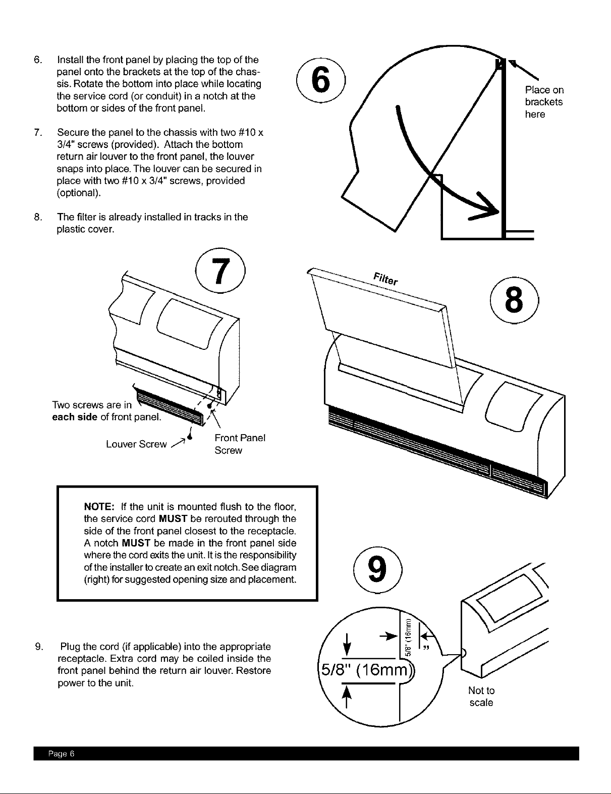
.
Install the front panel by placing the top of the
panel onto the brackets at the top of the chas-
sis. Rotate the bottom into place while locating
the service cord (or conduit) in a notch at the
bottom or sides of the front panel.
7.
Secure the panel to the chassis with two #10 x
3/4" screws (provided). Attach the bottom
return air louver to the front panel, the louver
snaps into place. The louver can be secured in
place with two #10 x 3/4" screws, provided
(optional).
.
The filter is already installed in tracks in the
plastic cover.
® Place on
brackets
here
®
Two
each side of front
!
Louver Screw 9 _ Front Panel
NOTE: If the unit is mounted flush to the floor,
the service cord MUST be rerouted through the
side of the front panel closest to the receptacle.
A notch MUST be made in the front panel side
where the cord exits the unit. It is the responsibility
ofthe installer to create an exit notch. See diagram
(right) for suggested opening size and placement.
g.
Plug the cord (if applicable) into the appropriate
receptacle. Extra cord may be coiled inside the
front panel behind the return air louver. Restore
power to the unit.
Screw
®
5/8" (16mm
Not to
scale
.... 711

Unit Operation
Rotatethe temperaturedial insmallincrements in
the warmer orcooler direction.Movingthe dial
more than 1/4"at atime may overcompensate and
result in an extreme hot or cold situation.
• If Thermostat is installed,
see Appendix A, page 11.
• If Central Desk Control is
installed, see Appendix B,
page 15.
Standard Unit Control Panel
COOL HEAT FAN ONLY OFF
Pushbutton Switch Operation
Control
Cool
Heat
Fan Only
Off
Temp
Fan Speed
Operation
Operates unit on cooling - cooling will not
begin if room temperature is below 60 E
Operates unit on heating. Some models
do not provide this selection.
Circulates air within the room. No heating
or cooling functions.
Shuts system down.
Temperature control - maintains room
temperature at the desired setting.
Counterclockwise - warmer
Clockwise - cooler.
Selects high speed or low speed.
WARNER TEt4 ? C OLER
Temperature Limiting Thermostat
1. Set thermostat knob to center of dial.
2. Remove four screws holding control panel. Pult up on
thermostat knob and remove.
3. Locate the two temperature limiting screws.These screws
are factory installed for a maximum temperature range of
60-90 ° E Each hole in dial plate represents approximately
a 4° change from the adjacent hole.
4. To adjust temperature range, move temperature limiting
screws to desired location.
5. Replace knob when desired range has been set.
6. Replace control panel.
EXAMPLE: To set a maximum temperature range of approxi-
mately 64 to 86° F,move screws to locations shown in diagram
at right.
LOW
Remove Knob
Temperature
L miring Screws
rl'

Heating Control
NOTE: Heat pump models only. Heat pump equipped models use
backup electric resistance heating coils. At extremely low outdoor
ambient temperatures, the heat pump is automatically disabled and the
unit operates solely on electric resistance heat.
O r"_
The heating control is located behind the front panel at the control box
bottom and is accessible through the return air louver opening. Its
function is to allow you to set the temperature range in which the heat
pump operates. This control switches the unit heat operation between
heat pump and electric resistance heat based on the outdoor ambient
COMMANDE DE CHAUFFAGE
temperature. These change over temperatures are based on the
settings of this control. In most cases, the factory setting (at approxi-
mately the one o'clock position) is adequate. Ifyou wish to change the
factory set point, insert a flat bladed screwdriver into the slot and turn counterclockwise to increase the changeover set
point.
In the event of a compressor malfunction, turn the screw to the extreme counterclockwise emergency heat position. The
heater will then cycle using electric resistance heat only. Note that in the emergency heat position, the compressor is locked
out, disabling both heat pump and cooling operations. CALL A SERVICE PERSON.
OMP6" 04'Z_
HEATING CONTROL
CONTROLDELCALOR
EM_RGENC'¢ HEAT
CHAUFFAGE D'UR_ENCE
DE EME_GENCIA
CYCLE DU
VENTILATEUR
CICLO DEL
VENTILADOR
VENT
AERATION
SALIDA (ESCAPE)
DEL AIRE
Fan Cycle Switch
The fan cycle switch is located behind the front panel at the bottom of the
control box. It is accessible through the return air louver opening. It is
CONTINUOUS
FAN
CYCLE
m
designed to operate the fan either continuously or intermittently with the
compressor or heating elements. When the switch is in the CONTINU-
OUS position, the fan will run continuously when the power switch is on.
With the fan cycle switch in the CYCLE position, the fan will run only when
the compressor or heating elements cycle on.
CYCLE
CICLO
recommended that this switch be set in the continuous position.
I NOTE: For maximum comfort and temperature control, it is
Vent Control
The vent control lever is located behind the front panel at the bottom of the
OPEN
OUVERT
ABIERTA
CLOSED
FERM_
CERRADA
control box. When the lever is up, (OPEN), outside air is mixed with indoor
air. When the lever is down, (CLOSED), no outside air is admitted into
room and room air is recycled through unit.
I NOTE: For peak operating efficiency the vent should remain closed. I
=
I
.... 711

Air Outlet Louver
I
I
I
I
I
The air outlet louver can be redirected to blow air either straight
up or at an angle into the room. To change the airflow direction,
I
\
\
\
remove the front panel, and the two screws on either side of the
louver. Reverse ends of louver and refasten.
Startup Checklist
Check the following:
_/ Unit is installed in compliance with all codes
and ordinances.
_/ Circuit breakers and wire sizes are correct.
_/ Filter is clean and in place.
_/ All panels are in place.
_/ Condenser air inlet and outlet free of obstruc-
tions.
Work area clean and free of debris.
NOTE: Units are to be installed and
checked for proper function by qualified
I
service personnel ONLY.
_/ Operate unit 20 minutes.
_/ Controls operation OK.
_/ Owner or operator instructed on control opera-
tion and routine maintenance.
_/ Name and phone number of service company
attached to unit or noted in telephone directory.
_/ Condensate drain adequate.
_/ Electrical cord is stored properly.
rl'l

11
Routine Maintenance
NOTE: Fan motor and all bearings are i
permanently sealed and do not require oiling.
,IJ Keep air intake filter clean. A dirty filter reduces the efficiency of the system and can cause erratic performance of
controls. It can also result in damage to the heating element and compressor. The unit is provided with a washable
filter that can be cleaned with soap and water. Inspect and clean the filter at least once a month or more often as
conditions dictate. Replace as necessary with a factory approved filter. To replace, slide it up and out through the
front cover immediately in front of the discharge grille opening.
,IJ Do NOT block off outside air flow. Efficient operation of the unit depends on free circulation of air over the indoor and
outdoor coils. Paper, leaves and other debris can reduce efficiency and cause serious damage to the compressor.
,IJ Coils should be inspected periodically for buildup of lint, dirt, leaves, other debris and bent fins. Clean coils with a soft
brush and compressed air or vacuum. Do NOT use sharp objects to clean coils.
,IJ Do NOT operate unit with front panel removed or without filter.
,IJ Ensure that objects such as drapes, furniture, or plants are not blocking free air flow of unit.
,IJ Keep doors and windows closed. Leaving them open will increase the work load on the unit and will result in higher
operating cost and excessive condensate.
,IJ Do NOT operate the unit during construction. Construction dust can clog filter and cause permanent damage to
other components.
I
I
,IJ Apply silicon based lubricant to the belt drive system as needed. DO NOT USE ANY SOLVENT BASED LUBRICANTS
SUCH AS WD-40 TM.
Apply silicon-based
lubricant to belt located
inside access door.
il Tel

Appendix A: Selection, Wiring &
Installation of Remote Thermostat
1. Remote Thermostat Selection & Wiring Guidelines for Packaged Terminal Air
Conditioners
Follow the instructions and recommendations of the thermostat manufacturer for installation and wiring. We do not
recommend aconventional heat pump thermostat with emergency electric heat selection for our heat pump units.
Our units make an automatic decision about turning on emergency heat if the heating demand cannot be met by
the heat pump.
A. Manual Changeover Thermostat
A single stage heat/cool thermostat with a terminal for heat damper operation is required. The recommended
thermostat/subbase is the Honeywell T-87F/Q539J. You can also substitute a thermostat with single stage cooling
and dual stages of heating.
Hone_
TERMINAL LETTER
Y
W
G
R
B
W2
THERMOSTAT TERMINAL
W&Y
Y
B
R
G
n_ell Thermostat Terminal Designation:
OPERATION
Cooling
Heating
Fan
24V common
to the thermostat
Heat Damper
Stage 2 Heating
Durin9 call for cooling.
During call for heating.
Continuous if the slider is inthe "Fan"
)osition, otherwise, intermittent.
Makes contact thru the thermostat
when a call for heating, cooling or fan is
made.
Made continuously during call for
heating.
Made if stage 1 (W) cannot handle the
heating load by itself.
CONTACT MADE
Wiring:
Wire as follows:
JUMPER
Yes
N/A
N/A
N/A
N/A
WIRE TO PTAC TERMINAL
N/A
Y
W
R
G
Manual Changeover Thermostat
Single Stage Cooling/Heating with Heat Damper Terminal
If using a thermostat with single cooling and dual heating
stages, install a jumper between the stage 2 heating terminal
(W2 on Honeywell) & the cooling terminal (Y on the
Honeywell), and wire to terminal "Y" on the UnitTerminal
Board.
Wire stage 1 heating (Wl on Honeywell) to terminal "W" on
the Unit Terminal Board. The remainder of the wiring is as
shown.
UnitTerminal Board
OR C y ,,m ,30 0 _ 0
" ,JUh PER
ThermostatTerminals ThermostatTerminals
UnitTerminal Board

B. Auto Changeover Thermostat
A single stage thermostat with dual stages of heating and auto changeover is needed. The recommended Thermostat/
Subbase combination is the Honeywell T-874C/Q 674E.
ThermostatTerminal Jumper Wire to PTACTerminal
Y & W2 YES N/A
Y N/A Y
Wl N/A W
R N/A R
G N/A G
Unit Terminal Board
: JUnnpE_
Thermostat Terminals
2. Installation
Follow Steps 1 through 5 (pages 4 and 5), then: ('/R _)
6. Locate the terminal strip on the right side of the control box. Attach
the thermostat subbase wires (field supplied) to the appropriately
labeled terminals as per widng diagram on the side of the chassis.
NOTE: No connections are made to the
"C" Terminal when one of the
manufacturer's thermostat subbases is
used.
Carefully route the wires alongside the conduit
or service cord. Attach the other end of the wires
to the appropriate terminals on the thermostat
subbase. See thermostat directions for proper
widng and mounting of thermostat.
7.
If the filter is not in place, install as shown.
mil*

Appendix A (Continued)
.
Install the front panel by placing the top of the panel
onto the brackets at the top of the chassis. Rotate
the bottom into place while locating the service
cord (or conduit) inthe notch at the bottom or sides
of the front panel.
®
®
g.
Secure the panel to the chassis with two #10 x
3/4" screws (provided). Attach the bottom return
air louver to the front panel. The louver snaps into
place. The louver can be secured in place with
two #10 x 3/4" screws provided (optional).
Front Panel
Screw
Louver Screw /_
NOTE: If the unit is mounted flush to the floor, the service cord
MUST be rerouted through the side of the front panel closest to
the receptacle. A notch MUST be made in the front panel side
where the cord exits the unit. Itis the responsibility of the installer
to create an exit notch. See the diagram for suggested opening
size and placement.
@
Not to scale
10. For 230/208 volt units, plug the cord (if applicable) intoan appropriate receptacle. For 265 volt units see Appendix
C on page 17.The extra cord may be coiled inside the front panel behind the return air louver. Restore power to the
unit.
rl

Appendix A (Continued)
Remote Thermostat 208V Operation
CONNECTION DIAGRAM
CAUTION
If the supply voltage is 208V, the low volt-
age transformer IVlUST be wired for 208V
operation. Failure to do so will result in lower
control voltages to the unit and can dam-
age low voltage components.
The simplified connection diagram at left shows the
factory configured wiring set for 240V operation. If
you are going to use 208V exclusively, switch the
two (2) black wires on the 240V post of the primary
side of the transformer to the 208V post. This will
ensure correct secondary (low) voltages for the unit.
This is only required on the remote thermostat units.
Remote Thermostat Unit Operation
These units are controlled by the use of a remote ther-
mostat that will cycle the unit to maintain desired room
temperature. See thermostat operating manual for de-
tails.
The fan speed switch on the control panel is indepen-
dent of the thermostat and controls the fan speed. If you
wish high speed fan operation, set switch to high. For low
mi,;,-i-ii i
Control
Fan Speed
Switch Operation
Selects high speed or low speed
Operation

Appendix B: Installation of
Central Desk Control
Follow steps 1 through 5 (pages 4 and 5), then:
®
6. Attach two wires from the central desk control to the
terminal board on the right side of the control box.The
central desk control must provide 24 volts AC to this
terminal board in order to switch the unit to the unoc-
cupied mode. When the 24 volts AC is turned off, the
unit returns to the occupied mode.
7.
8.
g.
If filter is not in place, locate and place as shown.
Install the front panel by placing the top of the panel
onto the brackets at top of the chassis. Rotate the
bottom into place while locating the service cord
(or conduit) in the notch at the bottom or sides of
the front panel.
Secure the panel to the chassis with two #10 x
3/4" screws (provided). Attach the bottom return
air louver to the front panel. The louver can be se-
cured in place with two #10 x 3/4" screws provided
(optional).
®
Place on
brackets
here.
(_ Filter
I
Front Panel
(not in place yet)
NOTE: Two screws are in
each side of front panel.
f. ....
Louver Screw _ I
m
_ Evaporator Coil
In//
....,1_- _ Thermostat Bulb
Front Panel
Screw
r

Appendix B (Continued)
NOTE: If the unit is mounted flush to the floor,
the service cord MUST be rerouted through the
side of the front panel closest to the receptacle.
A notch MUST be made in the front panel side
where the cord exits the unit. It is the
responsibility of the installer to create an exit
notch. See diagram for suggested opening size
and placement.
10.
Not to scale
Central Desk Control Operation
Units equipped with Central Desk Control are identical in operation with non-Central Desk Control models,
except in the "Unoccupied Mode" when all functions are disabled.
All conditions are with 24V power ON at Central Desk Control terminal board.
Plug the cord (if applicable) into the appropri-
ate receptacle. Extra cord may be coiled inside
front panel behind the return air louver. Restore
power to the unit.
IMPORTANT: Even if Central Desk Control is energized, the low temperature sensor will not
allow the temperature in the room to fall below 43 ° F. If the temperature falls below 43 ° F,
heat will come on until room temperature reaches 58° E

Appendix B (Continued)
Central Desk Control Low Voltage Wiring Specifications
Length of Run Total Length Wire Gauge
400 feet (120 m) 800 feet (240 m) 22
550 feet (155 m) 1100 feet (330 m) 20
1000 feet (300 m) 2000 feet (600 m) 18
1500 feet (450 m) 3000 feet (900 m) 16
2400 feet (730 m) 4800 feet (1440 m) 14
NOTE: The following points are the MINIMUM requirements needed to operate remote PTACS safely and
within design specifications.
1. Central Desk Control panel switches and transformers are field supplied. Switches should be SPST,
minimum rating of 0.5 amps inductive at 24 volts.
2. Units will not operate with switches closed. 24V supplied to the unit will DISABLE unit. See chart at left.
3. Minimum VA rafing of transformer is 9.8VA per unit. (9.8 X # of units determine totalVA needed for entire
installation).
4. Low voltage transformer is limited to maxVA per NEC 725-31.This may require multiple transformers for
large installations.
5. Consult the table at left for minimum wire gauges needed for any given low voltage wire run.
Appendix C. Electrical Wiring Options
For All 265V Models
265 volt units come shipped with a junction box under the control box. Remove the junction box cover and attach a 90°
electrical elbow and a 1/2" flexible conduit (separate accessory or field supplied). If not already in place, route the conduit
down through the floor taking care that hole in the floor is located directly below the notch in front panel. Make appropriate
electrical connections within the junction box, and reattach the junction box cover to the control box.
Wiring Diagram
Junction Box
Cover
1/2" Flexible
Conduit
(Accessory or
Rating Plate
Fuse Holder
_pire Nuts (Field
plied) /
Field Supplied)
conduit, make provisions to allow conduit to be removed
I NOTE: When installing a flush-floor mounted unit with
in case of future service needs to chassis.

Friedrich Air Conditioning Co.
P.O. Box 1540
San Antonio, Texas 78295-1540
(210) 357-4400
WALLMASTER ®PACKAGED TERMINAL PRODUCTS
(T Series)
AIR CONDITIONERS AND HEAT PUMPS
SAVETHIS CERTIFICATE. It gives you specific legal rights, and you may also haveother rights which may vary from state to state and
province to province.
In the event your unit needs servicing, contact your nearest authorized service center.When requesting service, please have the model
and serial number from your unit readily available. If you do not know the nearest service center, ask the company that installed your
unit or contact us - see address and telephone number above.
Unless specified otherwise herein,the following applies:
PACKAGEDTERMINALAIR CONDITIONERSAND HEATPUMPS
LIMITED WARRANTY-- FIRSTYEAR (Eighteen 18) months fromoriginal date of purchaseor twelve (12) months from installation). Any
defectinthe unit's materials or workmanship willbe repaired or replaced free of chargeby ourauthorizedservice centerduring normal working
hours; and
LIMITEDWARRANTY -- SECONDTHROUGH FIFTHYEAR (Sixty-six (66) months from the date of purchase or sixty (60) months from the
date of installation, whichever comes first) ON THE SEALED REFRIGERATION SYSTEM ANDTHE FLEX-DRIVE ® SYSTEM. Any part of
the seated refrigeration system,for theT Series,andthe Flex-Drive_System thatisdefective inmaterial or workmanshipwill berepaired or replaced
by our authorized service center during normal working hours.The sealed refrigeration system consists of the compressor, metering device,
evaporator,condenser, reversingvalve,check valve and interconnectingtubing. The Flex-DriveSystem® consists ofthe polyurethane beltand the
blower pulleys.
These warranties apply only while the unit remains at the original site and only to units installed inside the continental United States,
Alaska, Hawaii, Puerto Rico and Canada. The warranty applies only if the unit is installed and operated in accordance with the printed
instructions and in compliance with applicable local installation and building codes and good trade practices.
For International warranty information, contact the Friedrich Air Conditioning Company - International Division.
Reasonable proof mustbe presentedto establishthe original purchase date,otherwise the beginning date ofthis certificate willbeconsidered to be
our shipment date plus sixty days. Replacement parts can be new or remanufactured. Replacement parts and labor are only warranted for any
unused portionof the unit'swarranty. If the unit's normal use is for personal,family or household purposes, then freight and/or handling charges
associated with therepair and replacement pursuantto this warranty will be our responsibility
We will not be responsible for and the user will pa, for:
1. Service calls to:
(a) instruct on unit operation, (b) replace house fuses or correct house wiring, (c) clean or replace air filters, (d) remove the unit from
inaccessible locations, and/or (e) correct improper installations.
2. Parts orlabor provided byanyone other than an authorized service center.
3. Damages caused by:
(a) accident, abuse, negligence, misuse, riot, fire, flood, orActs of God, (b) operating the unit where there is a corrosive atmosphere
containing chlorine,fluorine, oranyother damaging chemicals (otherthan in a normal residentialenvironment), (c)unauthorized alteration
or repair ofthe unit,which inturn affects its stability orperformance,(d) failingto provideproper maintenance andservice, (e) usingother
than a "Seacoast Protected" unit ina coastal environment, (f)using an incorrect _owersource, (g) faulty installation or application of the
unit.
We shall not be liable for any incidental, conse( uential, or special damages or expenses in connection with any use or failure of this
unit. We have not made and do not make any representation or warranty of fitness for a particular use or purpose and there is not
implied condition of fitness for a particular use or purpose.We make no express warranties except as stated in this certificate. No one
is authorized to change this certificate or to create for us any other obligation or liability in connection with this unit. Any implied
warranties shall last for one year after the original purchase date. Some states and )rovincesdo not allow the exclusion or limitation of
incidental or consequential damages or do not allow limitations on how tong an impliedwarranty or condition lasts, so the above limitations or
exclusions may not apply to you.The provisions of this warranty are in addition to and not a modification of or subtraction from the statutory
warranties and other rights and remediesprovidedb' law.
In case of questions regarding the provisionsof this warranty, the English version will govern.

Friedrich Air Conditioning Co.
4200 North Pan Am Expressway * RO. Box 1540
San Antonio, Texas 78295-1540 • U.S.A.
Phone: (210) 357-4400
Fax: (210) 357-4480
rl'l-
 Loading...