

Page 1
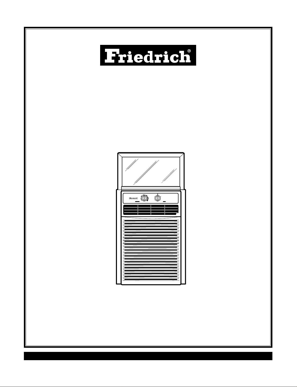
Room Air Conditioner
Service and Parts
Manual
Slider Casement
SV08 / SV10 / SV12 (01/05)
115Volts • SV08A10A • SV10A10A • SV12A10A
High
Cool
Med
Fan
Off
Mode
Temperature
Med
Cool
Low Cool
Low
Fan
CoolerWarmer
Page 2

—2—
1. PREFACE
1.1 SAFETY PRECAUTIONS................................2
1.2 INSULATION RESISTANCE TEST.................2
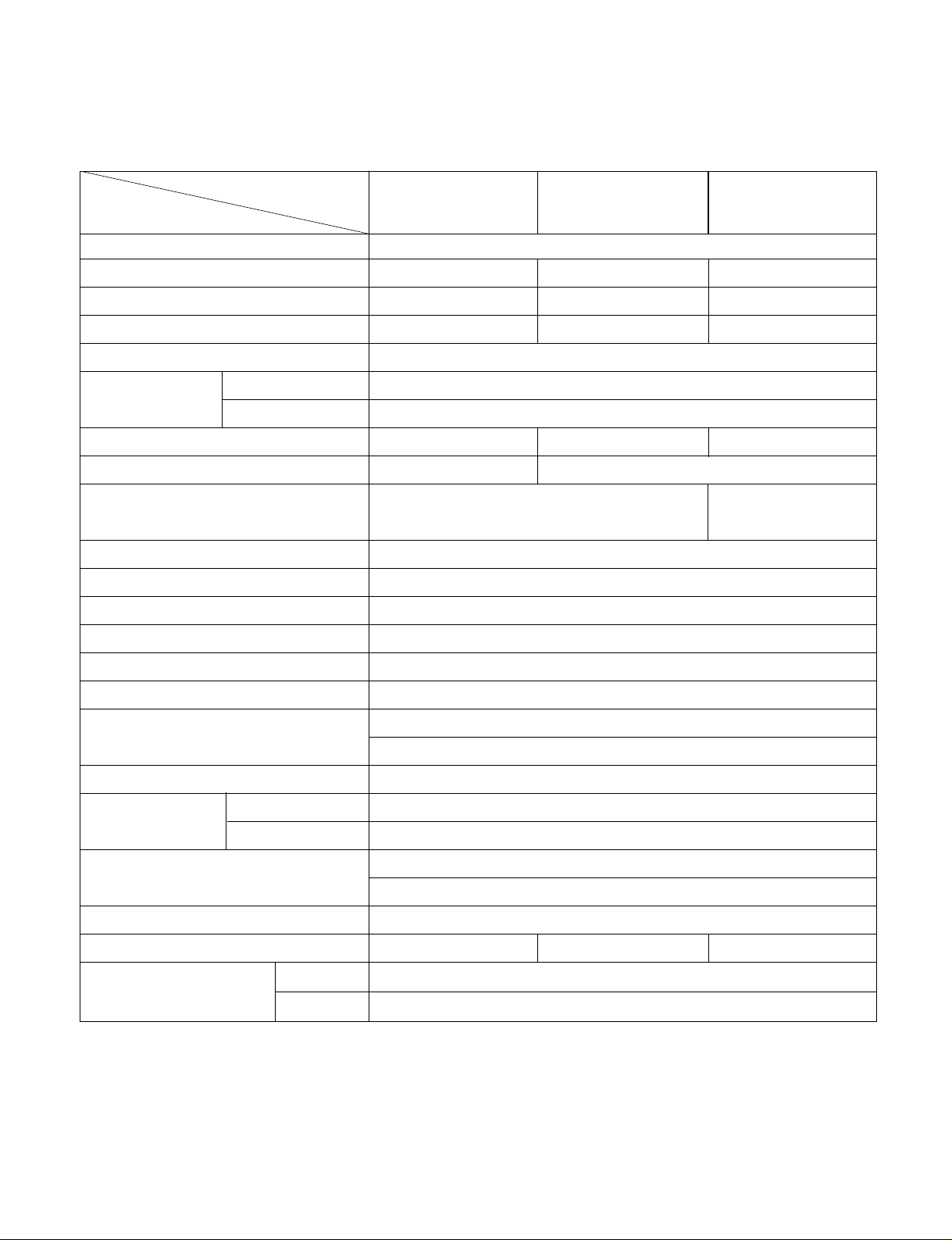
1.3 SPECIFICATIONS...........................................3
1.4 FEATURES......................................................4
1.5 CONTROL LOCATIONS .................................4
2.
DISASSEMBLY INSTRUCTIONS
2.1 MECHANICAL PARTS....................................5
2.1.1 FRONT GRILLE .....................................5
2.1.2 CABINET................................................5
2.1.3 CONTROL BOX .....................................5
2.2 AIR HANDLING PARTS..................................6
2.2.1 AIR GUIDE AND TURBO FAN...............6
2.2.2 FAN ........................................................6
2.2.3 SHROUD................................................7
2.3 ELECTRICAL PARTS......................................7
2.3.1 OVERLOAD PROTECTOR....................7
2.3.2 COMPRESSOR......................................7
2.3.3 CAPACITOR...........................................8
2.3.4 POWER CORD ......................................8
2.3.5 THERMOSTAT.......................................8
2.3.6 ROTARY SWITCH .................................8
2.3.7 MOTOR ..................................................9
2.4 REFRIGERATION CYCLE..............................9
2.4.1 CONDENSER.........................................9
2.4.2 EVAPORATOR.......................................9
2.4.3 CAPILLARY TUBE...............................10
3.
INSTALLATION
3.1 HOW TO INSTALL THE UNIT.......................12
3.2 CHECKING INSTALLATION.........................12
3.3 HOW TO DRAIN............................................12
3.4 WINDOW REQUIREMENTS.........................13
3.5 INSTALLATION KITS CONTENTS ...............13
3.6
HORIZONTAL SLIDING WINDOW INSTALLATION
.....14
3.7 CASEMENT WINDOW INSTALLATION .......15
4.
TROUBLESHOOTING GUIDE
4.1 OUTSIDE DIMENSIONS...............................16
4.2 PIPING SYSTEM...........................................16
4.3 TROUBLESHOOTING GUIDE......................17
5. SCHEMATIC DIAGRAM
5.1 CIRCUIT DIAGRAM ......................................21
5.2 CIRCUIT DIAGRAM ......................................22
6. EXPLODED VIEW..................................23
7. REPLACEMENT PARTS LIST........24
1. PREFACE
This
SERVICE MANUAL provides various service information, including the mechanical and electrical
parts etc. This room air conditioner was manufactured and assembled under a strict quality control system.
The refrigerant is charged at the factory. Be sure to read the safety precautions prior to servicing the unit.
1.1 SAFETY PRECAUTIONS
1. When servicing the unit, set the ROTARY SWITCH
or POWER SWITCH to OFF and unplug the power
cord.
2. Observe the original wire insulation.
If a short circuit is found, replace all parts which
have been overheated or damaged by the short
circuit.
3. After servicing the unit, make an insulation resistance test to protect the customer from being
exposed to shock hazards.
1.2
INSULATION RESISTANCE TEST
1. Unplug the power cord and connect a jumper
between 2 pins (black and white).
2. The grounding conductor (green) is to be open.
3. Measure the resistance value with an ohm meter
between the jumpered lead and each exposed
metallic part on the equipment at all the positions
(except OFF) of the ROTARY SWITCH.
4. The value should be over 1MΩ.
CONTENTS
Page 3
—3—
POWER SUPPLY
COOLING CAPACITY (Btu/h)
INPUT (W)
RUNNING CURRENT (A)
E.E.R (BTU/W.h)
INDOOR (°C)
OUTDOOR (°C)
REFRIGERANT (R-22) CHARGE
EVAPORATOR
CONDENSER
FAN, INDOOR
FAN, OUTDOOR
FAN SPEEDS, FAN/COOLING
FAN MOTOR
OPERATION CONTROL
ROOM TEMP. CONTROL
AIR DIRECTION CONTROL
CONSTRUCTION
PROTECTOR
COMPRESSOR
FAN MOTOR
POWER CORD
DRAIN SYSTEM
NET WEIGHT (lbs/kg)
OUTSIDE DIMENSION (inch)
(W x H x D) (mm)
1Ø115V, 60Hz
8,000 10,000 12,000
840 1,050 1,260
7.7 9.6 11.5
9.5
26.7(DB)* 19.4(WB)**
35(DB)* 23.9(WB)**
460g(16.2 oz) 520g(18.3 oz) 615g(21.7 oz)
2 ROW 16 STACKS, SLIT FIN TYPE
3 ROW 16 STACKS, SLIT FIN TYPE
2 ROW 23 STACKS, 3 ROW 23 STACKS,
LOUVER FIN TYPE LOUVER FIN TYPE
TURBO FAN
AXIAL FAN
2/3
6 POLES
ROTARY SWITCH
THERMOSTAT
VERTICAL LOUVER (RIGHT & LEFT)
HORIZONTAL LOUVER (UP & DOWN)
TOP-DOWN CHASSIS
OVERLOAD PROTECTOR
INTERNAL THERMAL PROTECTOR
3 WIRE WITH GROUNDING
ATTACHMENT PLUG (CORD-CONNECTED TYPE)
DRAIN PIPE SPLASHED BY FAN SLINGER
66/30 77/35 79/36
141/2 x 201/2 x 233/5
368 x 521 x 607
SV08A10A SV10A10A SV12A10A
MODELS
ITEMS
OPERATING
CONDITION
1.3 SPECIFICATIONS
1.3.1 FOR SV08A10A / SV10A10A / SV12A10A
* DB:Dry Bulb
**
WB:Wet Bulb
Page 4

—4—
1.4 FEATURES
• Designed for COOLING ONLY.
• Powerful and whispering cooling.
• Simple installation and service.
• Low air-intake, top cooled-air discharge.
1.5 CONTROL LOCATIONS
1.5.1 COOLING ONLY MODEL
• VENTILATION
The ventilation lever must be in the CLOSE position
in order to maintain the best cooling conditions.
When fresh air is necessary in the room, set the
ventilation lever OPEN position.
The damper is opened and room air is exhausted.
• TEMPERATURE
Thermostat will automatically control the temperature
of the room. Select a higher grade for a cooler
temperature in the room. The temperature is selected
by moving the knob to the desired position.
• MODE
- Turns air conditioner off.
- Med speed fan operation without cooling.
- Low speed fan operation without cooling.
- Cooling with high speed fan operation.
- Cooling with med speed fan operation.
- Cooling with low speed fan operation.
• Built-in adjustable THERMOSTAT
• Washable one-touch filter
• Compact size
• Reliable and efficient rotary compressor is equipped.
VENTCLOSE
OPEN
High
Cool
Med
Fan
Off
Mode
Temperature
Med
Cool
Low Cool
Low
Fan
CoolerWarmer
Inlet Grille
H
i
g
h
C
o
o
l
M
e
d
F
a
n
O
f
f
M
o
d
e
T
e
m
p
e
r
a
t
u
r
e
M
e
d
C
o
o
l
L
o
w
C
o
o
l
L
o
w
F
a
n
C
o
o
l
e
r
W
a
r
m
e
r
NOTE!
Before using the air conditioner
secure the front grille with two screws
enclosed with the owner’s manual.
1. Open the inlet grille downward and
remove the air filter.
2. Fasten the front grille with screws.
3. Reinstall the air filter.
4. Close the inlet grille.
Page 5
—5—
2.1 MECHANICAL PARTS
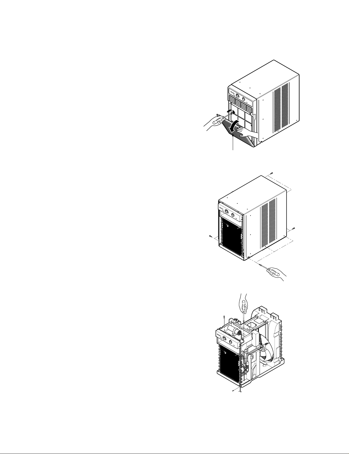
2.1.1 FRONT GRILLE
1. Open the inlet grille downward and remove the air
filter.
2. Remove the screws which fasten the front
grille.(See Figure 1)
3. Pull the front grille from the right side.
4. Remove the front grille.(There are 4 hooks.)
5. Re-install the components by referring to the
removal procedure, above.
2.1.2 CABINET
1. After disassembling the FRONT GRILLE, remove
the 6 screws which fasten the cabinet at both
sides.(See Figure 2)
2. Remove the 4 screws which fasten the cabinet at
back.
3. Remove the cabinet.
4. Re-install the components by referring to the
removal procedure, above.
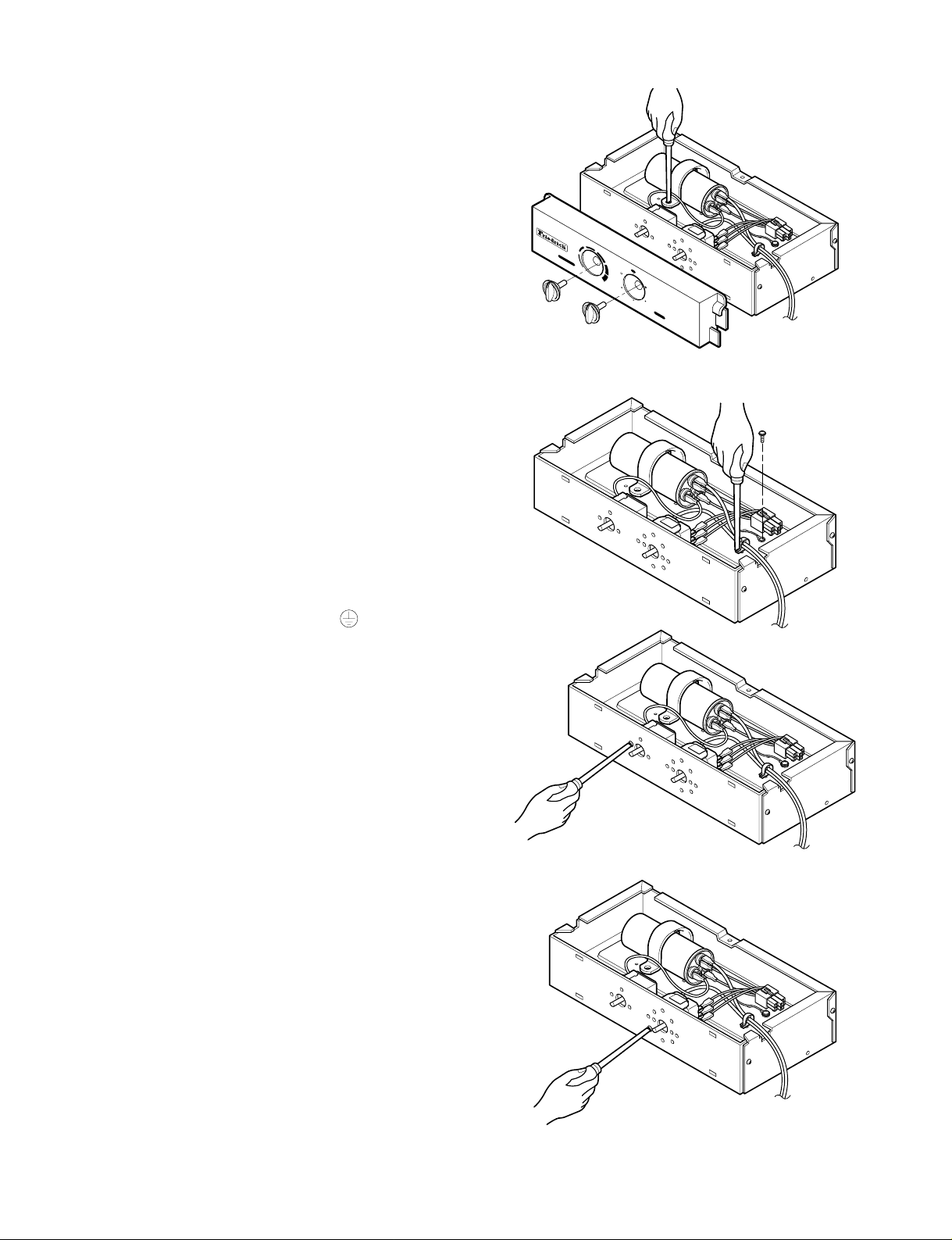
2.1.3 CONTROL BOX
1. Remove the front grille. (Refer to section 2.1.1)
2. Remove the cabinet. (Refer to section 2.1.2)
3. Remove the 1 screw which fasten the power cord.
(See Figure 3)
4. Disconnect the grounding screw from the
evaporator channel.
5. Remove the 2 screws which fasten the control
box.(See Figure 3)
6. Remove the housing which connects motor wire
in the control box.
7. Remove three leads which connect compressor.
8. Discharge the capacitor by placing a 20,000 ohm
resistor across the capacitor terminals.
9. Raise the control box upward completely.
10. Re-install the components by referring to the
removal procedure, above.
(Refer to the circuit diagram found on pages
21~22 in this manual and on the control box.)
Inlet Grille
H
i
g
h
C
o
o
l
M
e
d
F
a
n
O
f
f
M
o
d
e
T
e
m
p
e
r
a
t
u
r
e
M
e
d
C
o
o
l
L
o
w
C
o
o
l
L
o
w
F
a
n
C
o
o
l
e
r
W
a
r
m
e
r
H
i
g
h
C
o
o
l
M
e
d
F
a
n
O
f
f
M
o
d
e
T
e
m
p
e
r
a
t
u
r
e
M
e
d
C
o
o
l
L
o
w
C
o
o
l
L
o
w
F
a
n
C
o
o
l
e
r
W
a
r
m
e
r
H
i
g
h
C
o
o
l
M
e
d
F
a
n
O
f
f
M
o
d
e
T
e
m
p
e
r
a
t
u
r
e
M
e
d
C
o
o
l
L
o
w
C
o
o
l
L
o
w
F
a
n
C
o
o
l
e
r
W
a
r
m
e
r
2. DISASSEMBLY INSTRUCTIONS
— Before the following disassembly, set POWER SWITCH to OFF and disconnect the power cord.
Figure 1
Figure 3
Figure 2
Page 6
—6—
2.2 AIR HANDLING PARTS
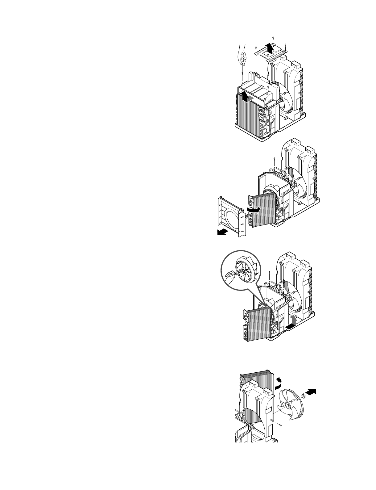
2.2.1 AIR GUIDE AND TURBO FAN
1. Remove the front grille. (Refer to section 2.1.1)
2. Remove the cabinet. (Refer to section 2.1.2)
3. Remove the control box. (Refer to section 2.1.3)
4. Remove the 4 screws which fasten the brace.
5. Remove the brace.
6. Remove the 2 screws which fasten the upper air
guide. (See Figure 4)
7. Remove the upper air guide.
8. Remove the 2 screws which fasten the
evaporator.
9. Move the evaporator forward while pulling it
upward slightly. (See Figure 5)
10. Remove orifice by pulling two taps.
11. Remove the clamp with a hand plier which
secures the turbo fan.
12. Remove the turbo fan. (See Figure 6)
13. Remove the motor. (Refer to section 2.3.7)
14. Remove the 2 screws which fastens the lower air
guide from the base pan.
15. Remove the 2 screws which fasten the motor
mount from the base pan.
16. Remove the 2 screws which fasten the lower air
guide and motor mount.
17. Move the lower air guide backward and pull out
from the base pan. (Move the lower air guide
carefully.)
18. Re-install the components by referring to the
removal procedure, above.
2.2.2 FAN
1. Remove the cabinet. (Refer to section 2.1.2)
2. Remove the brace (Refer to section 2.2.1)
3. Remove 6 screws which fasten the condenser.
4. Move the condenser to the right carefully.
5. Remove the clamp which secures the fan with a pair of
hand pliers.
6. Remove the fan. (See Figure 7)
7. Re-install by referring to the removal procedure.
Figure 4
Figure 5
Figure 6
Figure 7
Page 7

—7—
2.2.3 SHROUD
1. Remove the fan. (Refer to section 2.2.2)
2. Remove the shroud. (See Figure 8)
3. Re-install the components by referring to the
removal procedure, above.
2.3 ELECTRICAL PARTS
2.3.1 OVERLOAD PROTECTOR
1. Remove the cabinet. (Refer to section 2.1.2)
2. Remove the nut which fastens the terminal cover.
3. Remove the terminal cover. (See Figure 9)
4. Remove all the leads from the overload protector.
5. Remove the overload protector.
6. Re-install the components by referring to the
removal procedure, above.
2.3.2 COMPRESSOR
1. Remove the cabinet. (Refer to section 2.1.2)
2. Discharge the refrigerant system using a Freon
TM
Recovery System.
If there is no valve to attach the recovery system to
install one (such as a WATCO A-1) before venting
the FreonTM. Leave the valve in place after
servicing the system.
3. Remove the overload protector. (Refer to section
2.3.1)
4. After purging the unit completely, unbraze the
suction and discharge tubes at the compressor
connections.
5. Remove the 3 nuts and the 3 washers which
fasten the compressor to the base pan.
6. Remove the compressor. (See Figure 10)
7. Re-install the components by referring to the
removal procedure, above.
Figure 8
Figure 9
Figure 10
Page 8
—8—
2.3.3 CAPACITOR
1. Remove the cabinet. (Refer to section 2.1.2)
2. Remove the screw and the clamp which fasten the
capacitor.
3. Disconnect all the leads of capacitor terminals.
4. Re-install the components by referring to the
removal procedure, above. (See Figure 11)
2.3.4 POWER CORD
1. Remove the cabinet. (Refer to section 2.1.2)
2. Disconnect the grounding screw from the control
box.
3. Disconnect the 2 receptacles.
4. Remove a screw which fastens the cord clip.
(See Figure 12)
5. Remove the power cord.
6. Re-install the component by referring to the
removal procedure, above.
(Use only one ground-marked hole for ground
connection.)
7. If the supply cord of this appliance is damaged, it
must be replaced by the same cord that can be
obtained from an authorized parts dealer.
2.3.5 THERMOSTAT
1. Remove the cabinet. (Refer to section 2.1.2)
2. Remove the 2 screws which fasten the thermostat.
3. Disconnect 2 leads of thermostat terminals.
4. Remove the thermostat.
5. Re-install the components by referring to the above
removal procedure. (See Figure 13)
2.3.6 ROTARY SWITCH
1. Remove the cabinet. (Refer to section 2.1.2)
2. Remove the 2 screws which fasten the rotary
switch.
3. Disconnect all the leads of the rotary switch
terminals.
4. Remove the rotary switch.
5. Re-install the components by referring to the
above removal procedure. (See Figure 14)
Figure 11
Figure 12
Figure 13
Figure 14
T
e
m
p
e
r
a
t
u
r
e
Med
Fan
Warmer
Off
Cooler
High
Cool
Low
Fan
Low Cool
Med
Cool
M
o
d
e
Page 9

—9—
2.3.7 MOTOR
1. Remove the cabinet. (Refer to section 2.1.2)
2. Remove the turbo fan. (Refer to section 2.2.1)
3. Remove the fan. (Refer to section 2.2.2)
4. Remove the 4 screws which fasten the motor from
the Motor Mount. (See Figure 15)
5. Remove the motor.
6. Re-install the components by referring to the
removal procedure, above.(See Figure 15)
2.4 REFRIGERATING CYCLE
2.4.1 CONDENSER
1. Remove the cabinet. (Refer to section 2.1.2)
2. Remove the 4 screws which fasten the brace.
3. Remove the 4 screws which fasten the condenser
and shroud. (See Figure 16)
4. Remove the 2 screws which fasten the condenser
and base pan.
5. After discharging the refrigerant completely,
unbraze the interconnecting tube at the condenser
connections.
6. Remove the condenser.
7. Re-install the components by referring to notes on
p10. (See Figure 16)
2.4.2 EVAPORATOR
1. Remove the cabinet. (Refer to section 2.1.2)
2. Remove the control box.(Refer to section 2.1.3)
3. Remove the upper air guide. (Refer to section
2.2.1)
4. Remove the 2 screws which fasten the evaporator
to the lower air guide.
5. Carefully move the evaporator sideways.
(Refer to section 2.2.1)
6. After discharging the refrigerant completely,
unbraze the interconnecting tube at the evaporator
connections.
7. Remove the evaporator.
8. Re-install the components by referring to notes on
page 10. (See Figure 17)
Figure 15
Figure 16
Figure 17
Discharge the refrigerant system using a
FreonTMRecovery System.
If there is no valve to attach the recovery
system to install one (such as a WATCO A-1)
before venting the FreonTM. Leave the valve in
place after servicing the system.
CAUTION
Page 10
—10—
— Replacement of the refrigerant.
1. When replacing the refrigerant, be sure to
Discharge the refrigerant system using a Freon
TM
recovery System.
If there is no valve to attach the recovery system
to, install one (such as a WATCO A-1) before
venting the FreonTM. Leave the valve in place after
servicing the system.
2. After discharging the unit completely, remove the
desired component, and unbraze the pinch-off
tubes.
3. Solder service valves into the pinch-off tube ports,
leaving the valves open.
4. Solder the pinch-off tubes with Service valves.
5. Evacuate as follows.
1) Connect the vacuum pump, as illustrated figure
18A, on page 11.
2) Start the vacuum pump and slowly open
manifold valves A and B with two full turns
counterclockwise and leave the valves open.
The vacuum pump is now pulling through valves
A and B up to valve C by means of the manifold
and entire system.
3) Operate the vacuum pump for 20 to 30 minutes,
until 600 microns of vaccum is obtained. Close
valves A and B, and observe vacuum gauge for
a few minutes. A rise in pressure would
indicate a possible leak or moisture remaining in
the system. With valves A and B closed, stop
the vacuum pump.
4) Remove the hose from the vacuum pump and
place it on the charging cylinder. See figure
18B, on page 11.
Open valve C.
Discharge the line at the manifold connection.
5) The system is now ready for final charging.
6. Recharge as follows :
1) Refrigeration cycle systems are charged from
the High-side. If the total charge cannot be put
in the High-side, the balance will be put in the
suction line through the access valve which you
installed as the system was opened.
2) Connect the charging cylinder as shown in figure
18B, on page 11.
With valve C open, discharge the hose at the
manifold connection.
3) Open valve A and allow the proper charge to
enter the system. Valve B must remain closed.
4) If more charge is required, the high-side will not
take it. Close valve A.
5) With the unit running, open valve B and add the
balance of the charge.
a. Do not add the liquid refrigerant to the Low-
side.
b. Watch the Low-side gauge; allow pressure to
rise to 30 lbs.
c. Turn off valve B and allow pressure to drop.
d. Repeat steps b. and c. until the balance of the
charge is in the system.
6) When satisfied that the unit is operating
correctly, use the pinch-off tool with the unit still
running and clamp on to the pinch-off tube.
Using a tube cutter, cut the pinch-off tube about
2" from the top of the pinch-off tool. Use sil-fos
solder and solder pinch-off tube closed. Turn off
the unit, allow it to set for a while, and then test
the leakage of the pinch-off connection.
NOTES
If high vacuum equipment is used, adjust valves
A and B so they are opened only slightly for a few
minutes, then open slowly with the two full turns
counterclockwise. This will keep oil from foaming
and being drawn into the vacuum pump.
2.4.3 CAPILLARY TUBE
1. Remove the cabinet. (Refer to section 2.1.2)
2. After discharging the refrigerant completely,
unbraze the interconnecting tube at the capillary
tube. (see caution on previous page)
3. Remove the capillary tube.
4. Re-install the components by referring to notes on
page 11.
CAUTION
Page 11
—11—
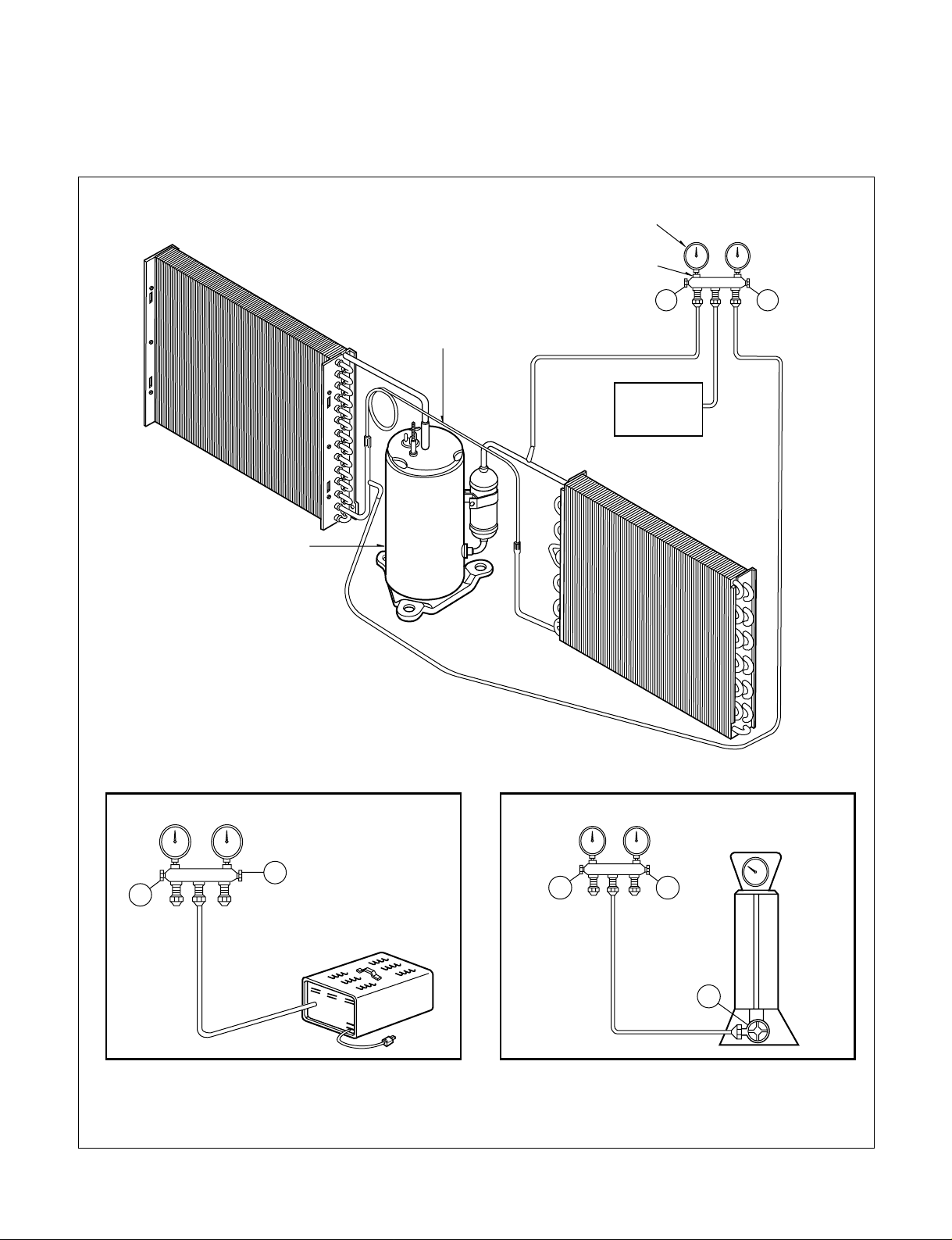
Equipment needed: Vacuum pump, Charging cylinder, Manifold gauge, Brazing equipment. Pinch-off tool
capable of making a vapor-proof seal, Leak detector, Tubing cutter, Hand Tools to remove components, Service
valve.
A
COMPOUND GAUGE
EVAPORATOR
(LOW PRESSURE SIDE)
COMPRESSOR
CAPILLARY TUBE
CONDENSER
(HIGH PRESSURE SIDE)
SEE INSETS
BELOW
MANIFOLD
GAUGE
B
Figure 18A-Pulling Vacuum
Figure 18B-Charging
A
B
EXTERNAL
VACUUM PUMP
A
CHARGING
CYLINDER
LOW
HI
B
C
Page 12
—12—
3. INSTALLATION
3.1 HOW TO INSTALL THE UNIT
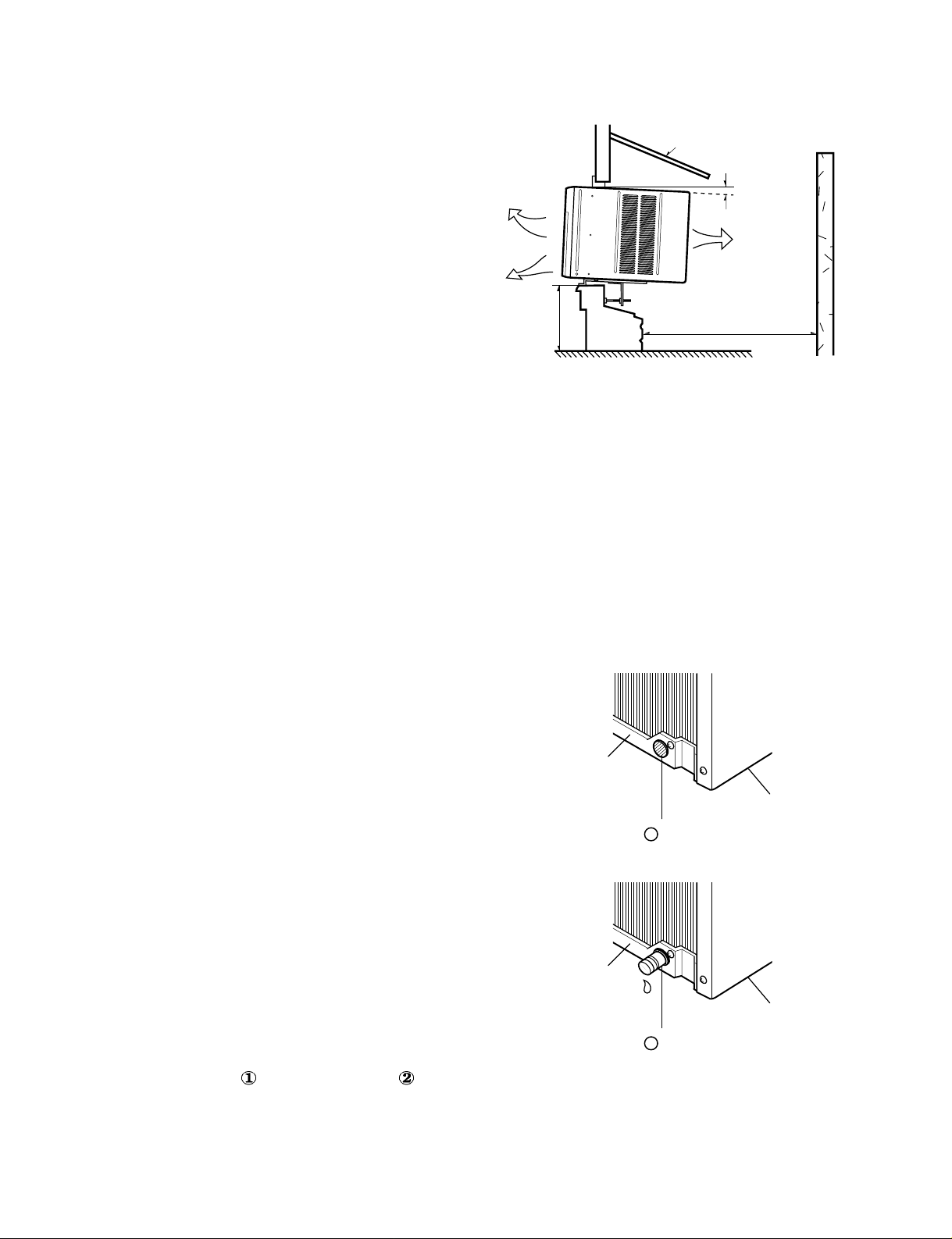
1. To avoid vibration and noise, make sure the unit is
installed securely and firmly.
2. Install the unit where the sunlight does not shine directly
on the unit.
If the unit receives direct sunlight, build an awning to
shade the cabinet.
3. There should be no obstacle, like a fence, within 20"
which might restrict heat radiation from the condenser.
4. To prevent reducing performance, install the unit so that
louvers of the cabinet are not blocked.
5. Install the unit with a slight downward slope towards the
outside (about 1/4"), to ensure that all condensate drains
outside.
6. Install the unit with its bottom portion 30~60" above the
interior floor level.
7. Stuff the foam gasket between the top of the unit and the
wall to prevent air and insects from getting into the room.
8. The power cord must be connected to an independent
circuit. The green wire must be grounded.
9. Connect the drain tube to the base pan hole in the rear
side if you need to run a drain hose.(consult a dealer).
Plastic hose or equivalent may be connected to the drain
tube.
3.2 CHECKING INSTALLATION
The setting conditions must be checked prior to
initial start up.
The items mentioned below are important check
points to review when the installation is complete.
1. A grounding wire (Green or Green and Yellow) is
provided in the power cord. The green wire must
be grounded.
2. Connect to a single-outlet 15A circuit.
3. To avoid vibration or noise, make sure the air
conditioner is securely installed.
4 Avoid placing furniture or draperies in front of the
air inlet and outlet.
3.3. HOW TO DRAIN
(When using drain pipe)
The air conditioner must be installed with a slight tilt
towards the outside for proper water drainage.
On exceptionally hot and humid days the air
conditioner may overflow condensed water to the
outside.
If the air conditioner is used in a high humidity
zone, exchange the DRAIN CAP for the
DRAIN PIPE.(See Figure 20, Figure 21)
About 1/4"
30"~60"
Awning
Cooled air
Fence
Over 20"
Heat
radiation
BOTTOM
DRAIN CAP
1
BASE PAN
BOTTOM
DRAIN PIPE
2
BASE PAN
Figure 20
Figure 21
Figure 19
Page 13
—13—
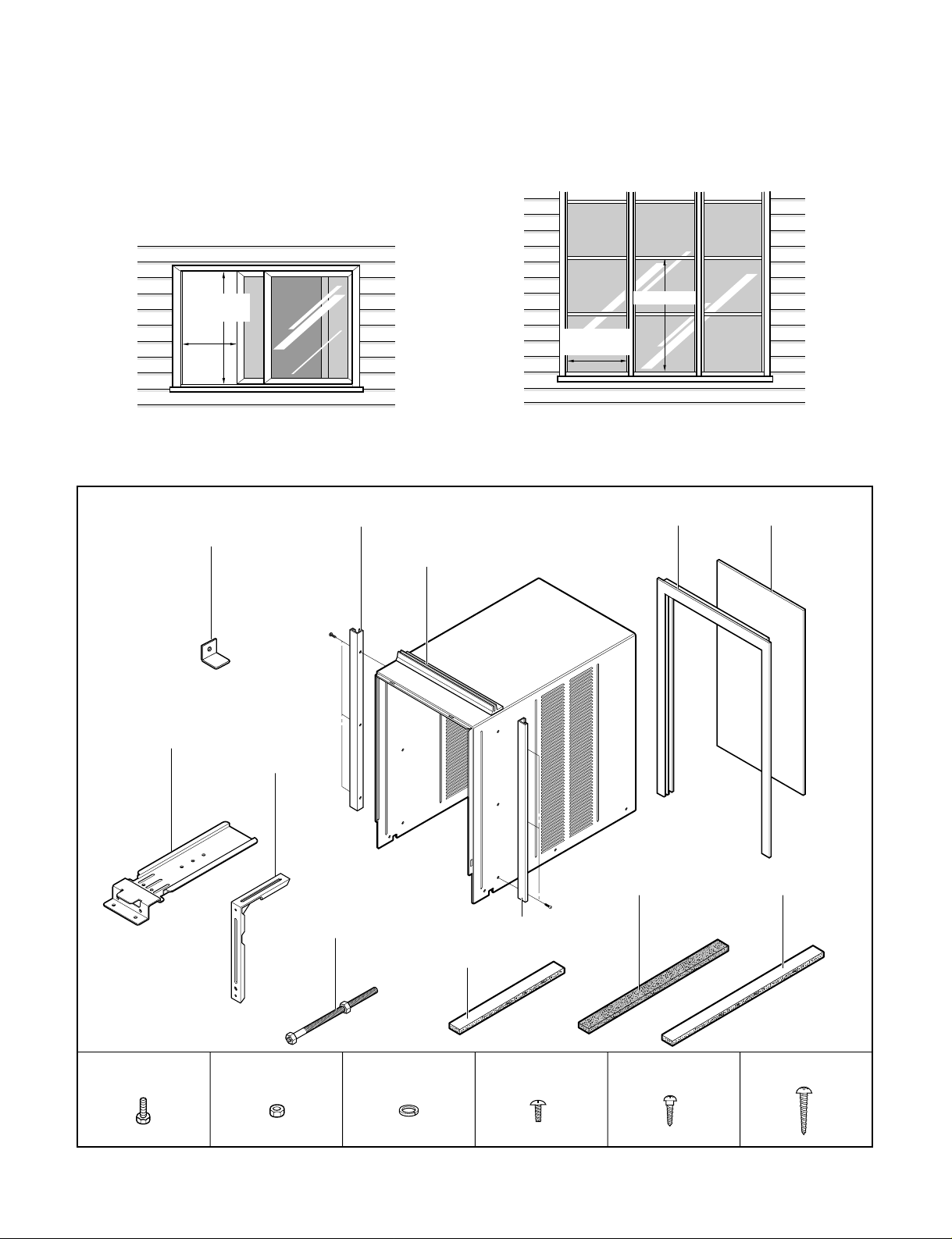
3.4 WINDOW REQUIREMENTS
1. These instructions are for a horizontal sliding or a
casement window.
2. The electrical outlet must be within reach of the
power cord.
For installation in a casement window, the window
frame assembly and the side of the building must be
adequate to support the weight of the air conditioner.
3.5 INSTALLATION KIT CONTENTS
21" min.
40 1/2" max.
15 1/2"
min.
Horizontal sliding window
21 1/2" min.
15 1/2" min.
16 1/2" max.
Casement window
Nut (2) Washer (2) Type A (9)
Type B (3) Type C (8)
Bolt (2)
CurtainWindow Locking
Bracket
Side Guide
Support Bracket
Leveling
bolt & nut
Bracket
Side Guide
Upper Guide
Curtain Frame
Side Guide SealFoam Seal Gasket
Window Track Seal
Page 14
—14—
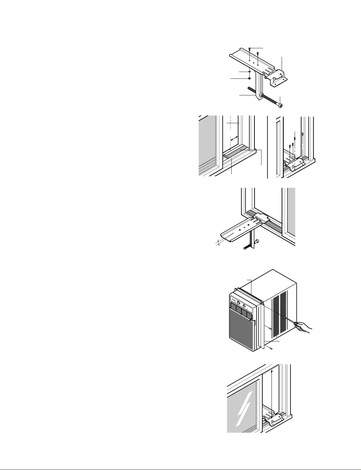
1. Loosely attach the support bracket to the bottom of
bracket using bolts, washers, and nuts. Attach the
leveling bolt and nut. (See Figure 22)
2. Remove protective backing from window track seal
and apply seal to window track. (See Figure 23)
3. Measure and lightly mark a line 8-1/4" from window
jamb. Center the support bracket assembly on the
window track and fasten with 4-type C screws. (See
Figure 23)
4. Put the support bracket against the outside wall and
tighten the bolts on top of the bracket. Adjust the
leveling bolt so that the air conditioner will be installed
with a very slight tilt (about 1/4") downward toward the
outside for proper drainage.
Tighten the nut. (See Figure 24)
NOTE: DO NOT drill a hole in the bottom of the base
pan. The air conditioner is designed to operate
with the bottom of the base pan approximately
half-full of water.
5. Fasten side guides to the sides of the air conditioner
using 3-type A screws per guide. start with first screw
at middle of guide. (See Figure 25)
6. Fasten upper guide on the top of the air conditioner
using 3-type A screws. (See Figure 25)
7. Measure height of window opening from top of
bracket assembly as shown Fig. 26.
Subtract 20-3/4". Mark this measurement on curtain
and cut the curtain. (See Figure 26)
Window T r ack
Window T r ack
Seal
Fastening Side Guides
Upper Guide
Side Guide
WindoWindow jambw jambWindow jamb
Type C screype C screwType C screw
Outside Wall
Bracket
Support Bracket
Nut
Washer
Leveling Bolt & Nut
Bolt
about 1/4"
H
i
g
h
C
o
o
l
M
e
d
F
a
n
O
f
f
M
o
d
e
T
e
m
p
e
r
a
t
u
r
e
M
e
d
C
o
o
l
L
o
w
C
o
o
l
L
o
w
F
a
n
C
o
o
l
e
r
W
a
r
m
e
r
811/16"
Figure 22
Figure 23
Figure 24
Figure 25
Figure 26
3.6 HORIZONTAL SLIDING WINDOW INSTALLA TION
Page 15
—15—
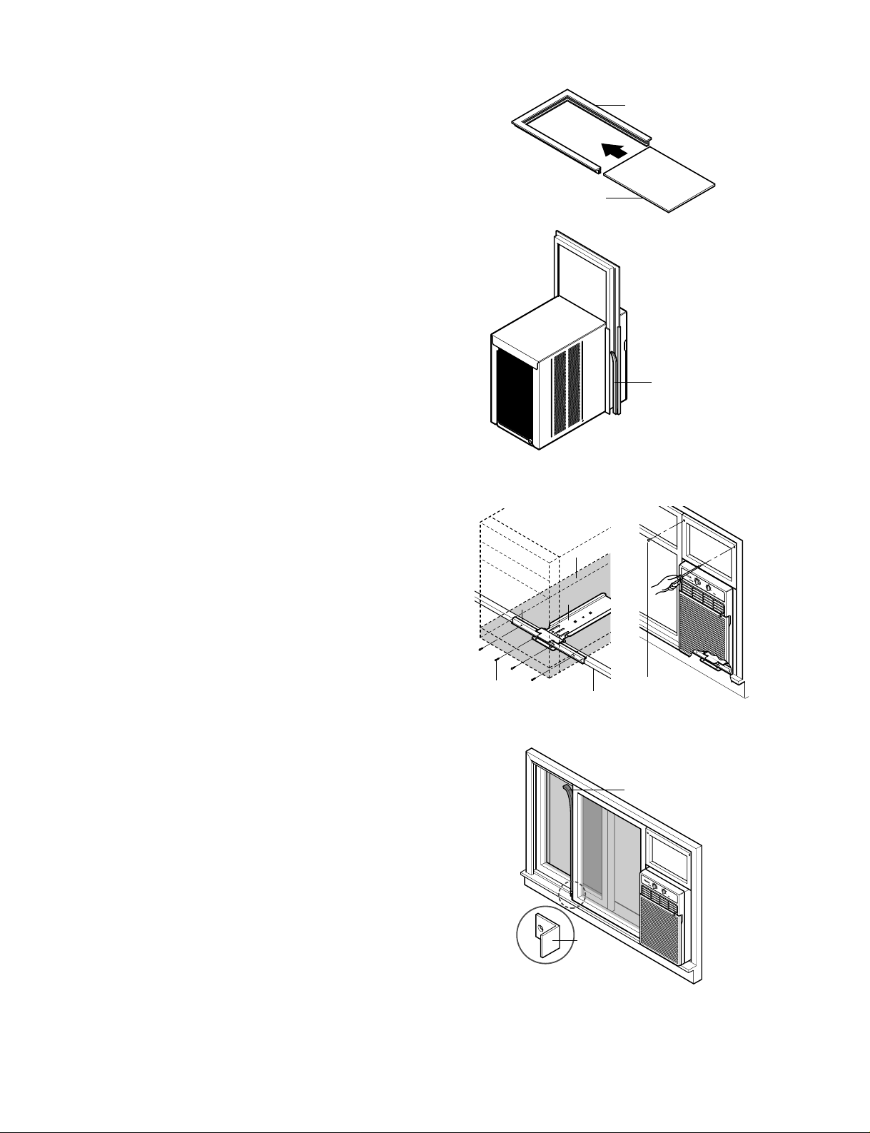
8. Slide curtain into curtain frame. Slide curtain frame
assembly into side guides of the air conditioner
cabinet. Make sure curtain is firmly enclosed on all
sides by the frame. (See Figure 27)
9. Cut side guide seal into 2 equal lengths. Remove
protective backing and apply it to the rear side of
cabinet side guides, starting just below curtain frame
assembly. Pinch off excess length so seal is even with
the bottom of side guide. (See Figure 28)
10. Place air conditioner in window opening. It should sit
on bracket assembly so that curtain frame and
cabinet side guides are against top and side window
jambs. Mate front of bracket with base guide
attached to the bottom of base pan.
11. Drill 1/8 inch holes in window track through the
existing holes on base guide. Screw 4-type C screws
through the holes. (See Figure 29)
12. If this is a casement window installation, proceed to
casement window installation. If not, slide inner
window sash firmly against side of the cabinet.
13.
Drill 1/8 inch hole in window jamb to align with the
existing holes in the curtain frame. Attach curtain
frame to window frame with 2-type B screws.
(See
Figure 29)
NOTE: Check all seals and plug any remaining air gaps
with a suitable weatherproof caulk.
14. If this is a casement window installation, proceed to
casement window installation. If not, stuff the foam
seal strip between the vertical sash and the window
glass.
(See Figure 30)
15. Attach the window locking bracket with a type B
screw.
(See Figure 30)
3.7 CASEMENT WINDOW
INSTALLATION
• Installation procedure is the same as that described in
steps 1 through 11 and step 13 of the horizontal sliding
window installation.
• If the window opening is wider than 15-3/4" you will
need to install a filler panel. Make this panel from 3/4
inch thick wood and run it the full length of the window.
Attach it securely to the window frame and paint it to
protect it from the weather.
• Since styles and sizes of casement windows vary
widely, it is advisable to have the air conditioner
installed by someone skilled in this type of installation.
Curtain Frame
Curtain
Window
locking
bracket
Foam seal strip
Apply weather seal
to side guides
just below edge of
Curtain Frame.
Type B screwType B screw
Hi
gh
C
oo
l
M
ed
Fa
n
O
ff
M
o
d
e
T
e
m
p
e
r
a
t
u
r
e
Me
d
C
oo
l
Lo
w C
o
ol
Low
F
a
n
C
oo
ler
W
a
r
me
r
H
i
g
h
C
o
o
l
M
e
d
F
a
n
O
f
f
M
o
d
e
T
e
m
p
e
r
a
t
u
r
e
M
e
d
C
o
o
l
L
o
w
C
o
o
l
L
o
w
F
a
n
C
o
o
l
e
r
W
a
r
m
e
r
Figure 27
Figure 28
Figure 29
Figure 30
Base GuideBase Guide
Type C screw
Base panBase pan
BracketBracket
Window TrackWindow Track
Page 16
—16—
4. TROUBLESHOOTING GUIDE
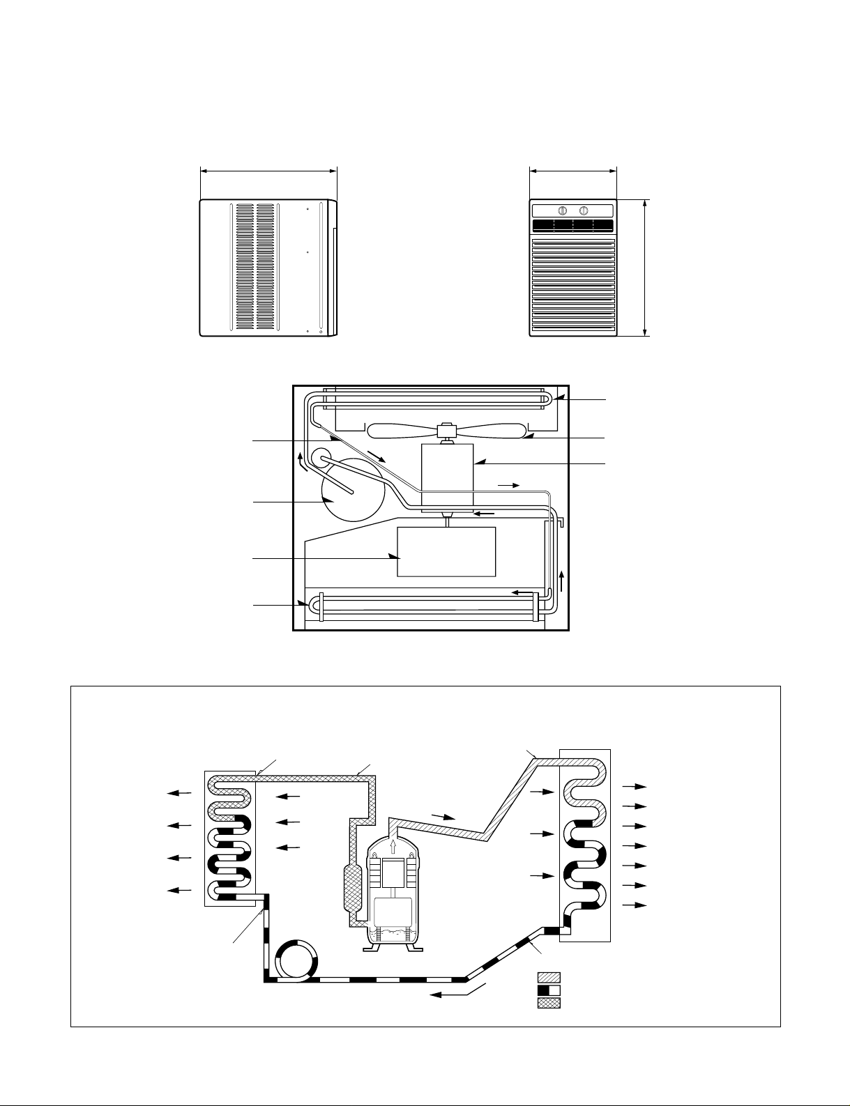
4.1 OUTSIDE DIMENSIONS
368(14 1/2)
521(20
1
/
2
)
607(23 3/5)
CAPILLARY TUBE
COMPRESSOR
TURBO FAN
EVAPORATOR COIL
CONDENSER COIL
FAN
MOTOR
4.2 PIPING SYSTEM
Following is a brief description of the important components and their functions in the refrigeration system.
Refer to Fig. 31 to follow the refrigeration cycle and the flow of the refrigerant in the cooling cycle.
(LIQUID REFRIGERANT)
CAPILLARY TUBE
OUTSIDE COOLING
AIR FOR REFRIGERANT
PASS THROUGH
SUCTION LINE
COOL LOW PRESSURE VAPOR
COOLED
AIR
COMPLETE LIQUID
BOIL OFF POINT
LIQUID
PRESSURE
DROP
ROOM AIR HEAT LOAD
VAPOR INLET
HOT
DISCHARGED
AIR
LIQUID OUTLET
HIGH PRESSURE VAPOR
LIQUID REFRIGERANT
LOW PRESSURE VAPOR
ROOM AIR CONITIONER
EVAPORATOR COIL CONDENSER COIL
CYCLE OF REFRIGERATION
MOTOR
COMPRESSOR
OIL
Figure 31
Unit: mm(inchs)
Page 17
—17—
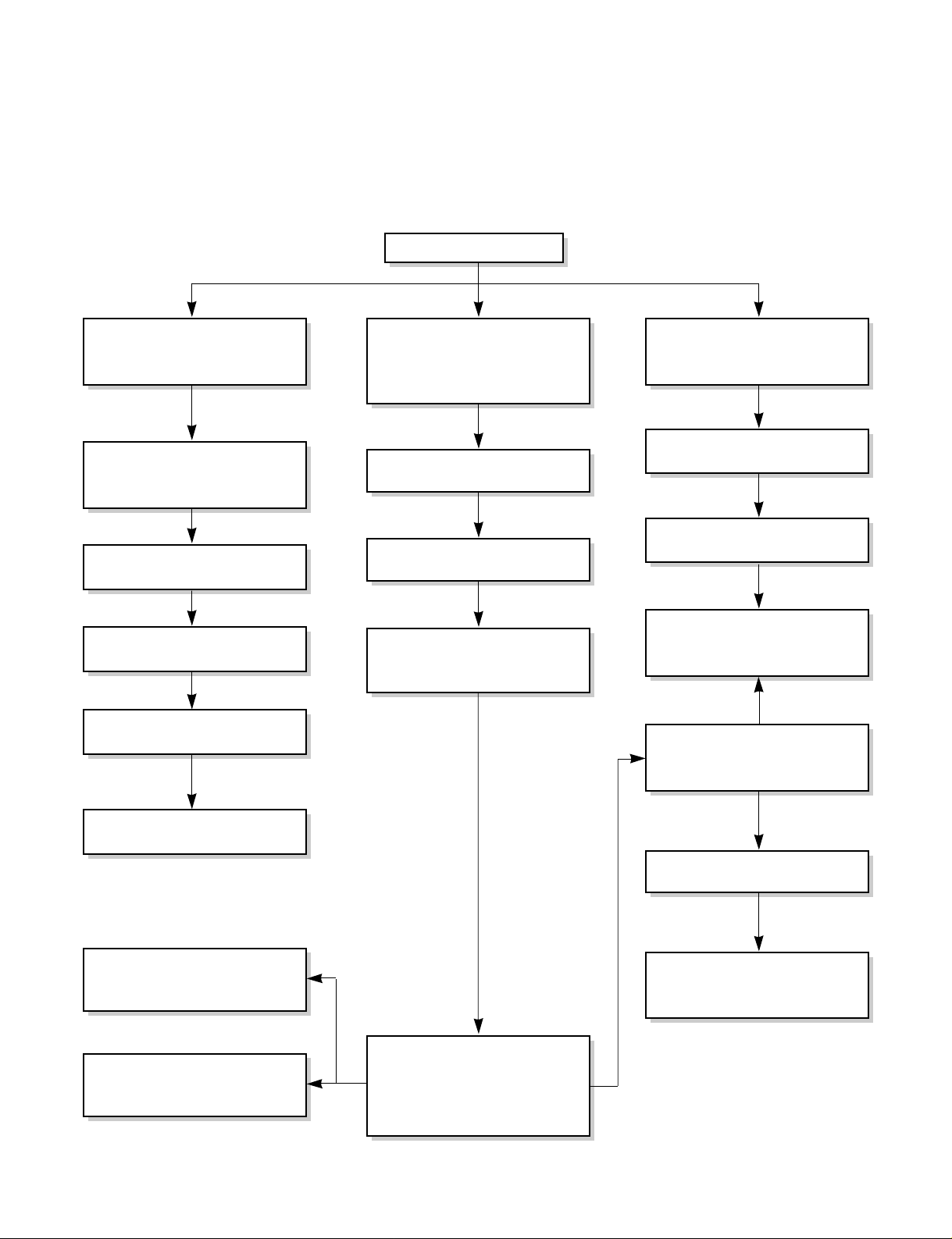
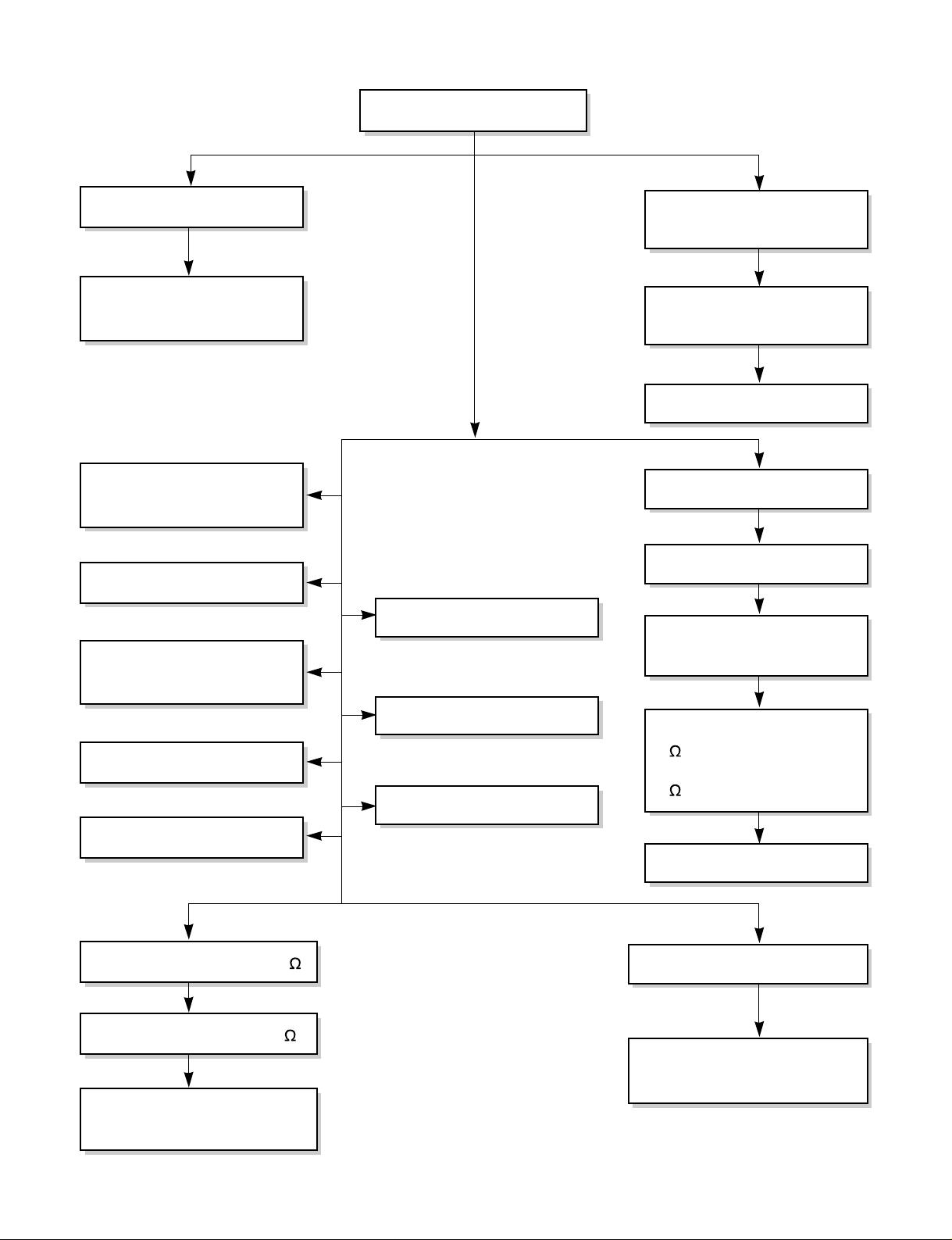
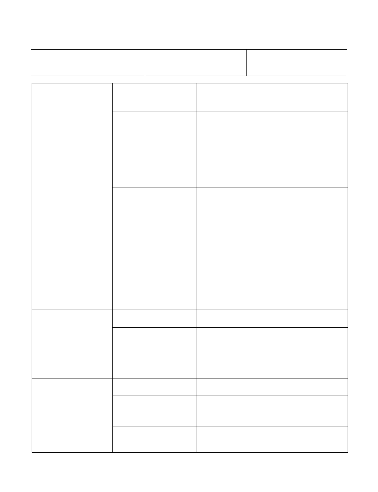
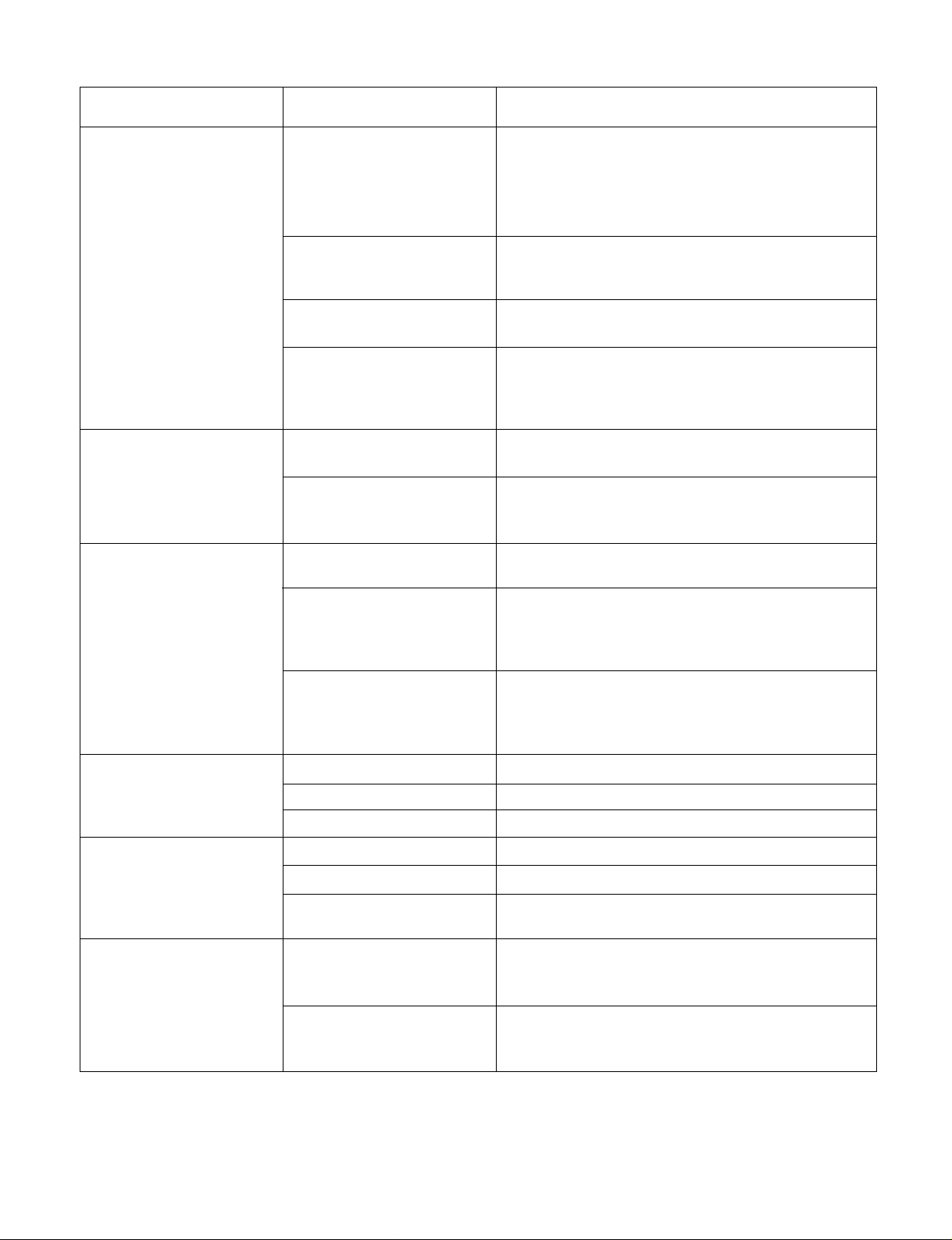
4.3 TROUBLESHOOTING GUIDE
In general, possible trouble is classified in two kinds.
The one is called Starting Failure which is caused from an electrical defect, and the other is ineffective Air
Conditioning caused by a defect in the refrigeration circuit and/or improper application.
Unit runs but poor cooling.
Ineffective Cooling
Check outdoor coil
(heat exchanger) & the fan
operation.
Check for gas leakage.
Repair gas leak.
Replace unit if the
unit is beyond repair.
Satisfactory operation with
temperature difference of
inlet & outlet air ;
44~50°F(7~10°C)
Check heat load
increase.
Clean condenser.
Not on separate circuit.
Check inside gas
pressure.
Adjustment of refrigerant
charge.
Malfunction of compressor.
Replacement of
compressor.
Check cold air circulation
for smooth flow.
Dirty indoor coil
(Heat exchanger)
Correct above problem
Check clogging in refrigeration system.
Repair clogging in refrigeration system.
Obstruction at air outlet
Clogged air filter
Malfunction of fan
Page 18
—18—
Fails to Start
Check circuit breaker
and fuse.
Gas leakage of feeler bulb
of thermostat
Check control switch.
Fan only fails to start.
Improper wiring.
Defective of fan motor
capacitor.
Irregular motor resistance
(
).
Irregular motor insulation
(
).
Replacement of fan motor.
Tests normal but fails to start.
Replacement of compressor
(locking of rotor, metal).
Improper thermostat setting.
Loose terminal connection.
Improper wiring.
Irregular motor resistance ( )
Irregular motor insulation ( )
Replacement of compressor
(Motor damaged)
Drop of power voltage.
Capacitor check.
Replacement
Compressor only fails to
start.
Defective of compressor
capacitor.
Check power source.
Check control switch
setting.
Page 19
—19—
COMPLAINT CAUSE REMEDY
Check voltage at outlet. Correct if none.
Check voltage to rotary switch. If none, check power
supply cord. Replace cord if circuit is open.
Check switch continuity. Refer to wiring diagram for
terminal identification. Replace switch if defective.
Connect wire. Refer to wiring diagram for terminal
identification. Repair or replace loose terminal.
Test capacitor.
Replace if not within ±10% of manufacturer's rating.
Replace if shorted, open, or damaged.
Fan blade hitting shroud or blower wheel hitting
scroll. Realign assembly.
Units using slinger ring for condenser fan must have
1
/4to 5/16inch clearance to the base. If it hits the
base, shim up the bottom of the fan motor with
mounting screw(s).
Check fan motor bearings; if motor shaft will not
rotate, replace the motor.
Check voltage. If not within limits, call an electrician.
Test capacitor.
Check bearings. Does the fan blade rotate freely?
If not, replace fan motor.
Pay attention to any change from high speed to
low speed. If the speed does not change, replace the
motor.
If cracked, out of balance, or partially missing,
replace it.
If cracked, out of balance, or partially missing,
replace it.
Tighten it.
If knocking sounds continue when running or loose,
replace the motor. If the motor hums or noise
appears to be internal while running, replace motor.
Check voltage.
If not within limits, call an electrician.
Check the wire connections, if loose, repair or
replace the terminal. If wires are off, refer to wiring
diagram for identification, and replace. Check wire
locations. If not per wiring diagram, correct.
Check for continuity, refer to the wiring diagram for
terminal identification. Replace the switch if circuit is
open.
No power
Power supply cord
Rotary switch
Wire disconnected or
connection loose
Capacitor (Discharge
capacitor before testing.)
Will not rotate
Revolves on overload.
Fan
Blower
Loose clamper
Worn bearings
Voltage
Wiring
Rotary
Fan motor will not run
Fan motor runs
intermittently
Fan motor noise
Compressor will not run,
but fan motor runs
NAME PLATE RATING MINIMUM MAXIMUM
115V ±10% 103.5V 126.5V
ROOM AIR CONDITIONER VOLTAGE LIMITS
Page 20
—20—
COMPLAINT CAUSE REMEDY
Check the position of knob If not at the coldest
setting, advance the knob to this setting and restart
unit.
Check continuity of the thermostat. Replace
thermostat if circuit is open.
Check the capacitor.
Replace if not within ±10% of manufacturers rating.
Replace if shorted, open, or damaged.
Check the compressor for open circuit or ground. If
open or grounded, replace the compressor.
Check the compressor overload, if externally
mounted. Replace if open. (If the compressor
temperature is high, remove the overload, cool it,
and retest.)
Check the voltage.
If not within limits, call an electrician.
Check overload, if externally mounted.
Replace if open. (If the compressor temperature is
high, remove the overload, cool, and retest.)
If not running, determine the cause. Replace if
required.
Remove the cabinet. inspect the interior surface of
the condenser; if restricted, clean carefully with a
vacuum cleaner (do not damage fins) or brush.
Clean the interior base before reassembling.
If condenser fins are closed over a large area on the
coil surface, head pressures will increase, causing
the compressor to overload. Straighten the fins or
replace the coil.
Test capacitor.
Check the terminals. If loose, repair or replace.
Check the system for a restriction.
If restricted, clean or replace.
Close if open.
Determine if the unit is properly sized for the area to
be cooled.
Check the set screw or clamp. If loose or missing,
correct. If the blower or fan is hitting the air guide,
rearrange the air handling parts.
Remove the cabinet carefully and rearrange tubing
so that it doesn't contact the cabinet, compressor,
shroud, and barrier.
Thermostat
Capacitor (Discharge
capacitor before servicing.)
Compressor
Overload
Voltage
Overload
Fan motor
Condenser air flow
restriction
Condenser fins (damaged)
Capacitor
Wiring
Refrigeration System
Air filter
Exhaust damper door
Unit undersized
Blower or fan
Copper tubing
Compressor will not run,
but fan motor runs.
Compressor cycles on
overload.
Compressor cycles on
overload.
Compressor cycles on
overload.
Insufficient cooling or
heating
Excessive noise
Page 21
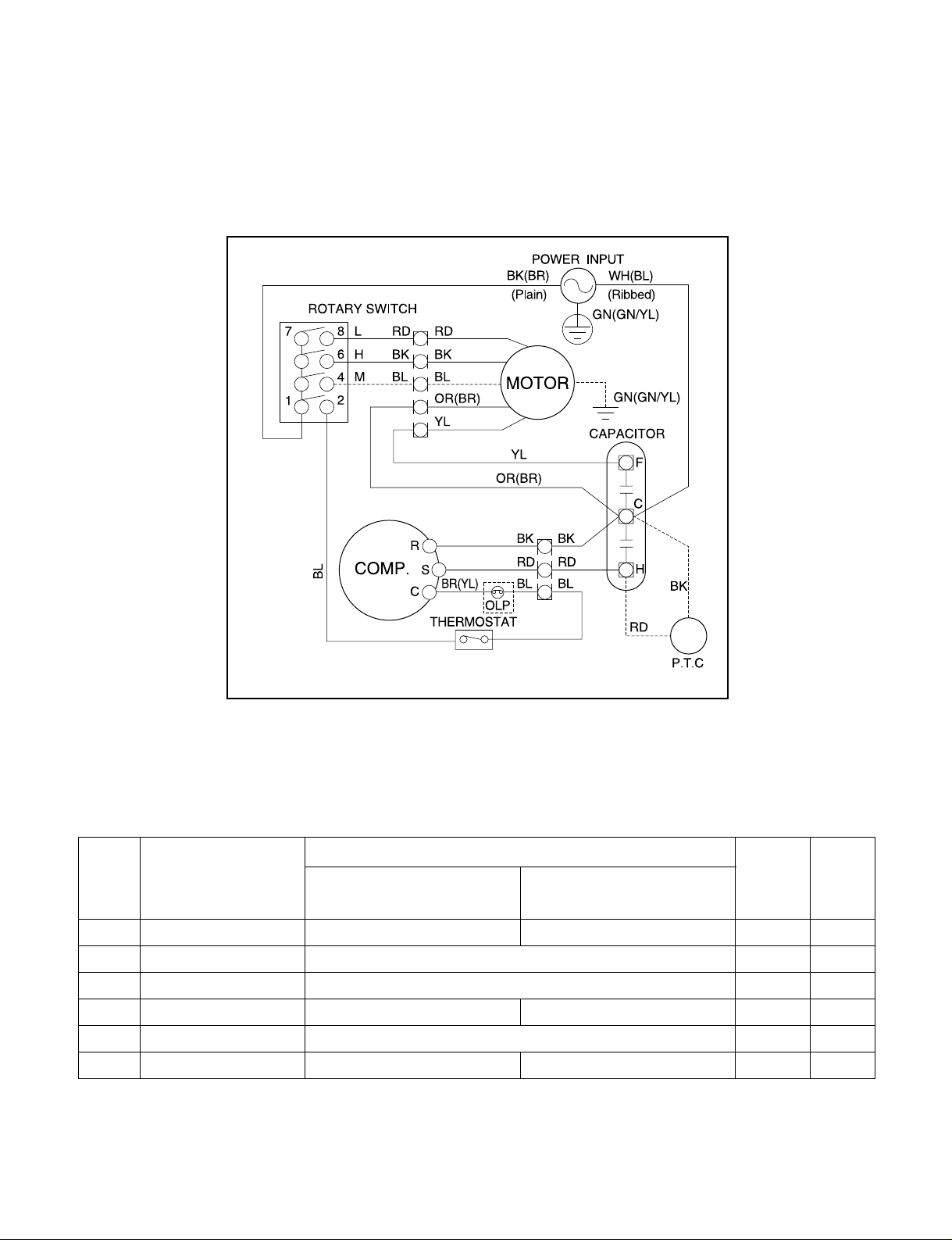
5. SCHEMATIC DIAGRAM
5.1 CIRCUIT DIAGRAM
■ MODEL : SV10A10A / SV1210A
—21—
SV10A10A SV12A10A
PART NO.
1 POWER CORD - - 1 S
2 ROTARY SWITCH 67300501 1 S
3 FAN MOTOR 67303015 1 S
4 CAPACITOR 67300709 - 1 S
5 THERMOSTAT 67300403 1 S
6 COMPRESSOR 67301614 67301615 1 S
LOCATION
NO.
DESCRIPTION
RE-
MARKS
Q'TY
PER SET
S: Service Parts
N: Non Service Parts
Page 22
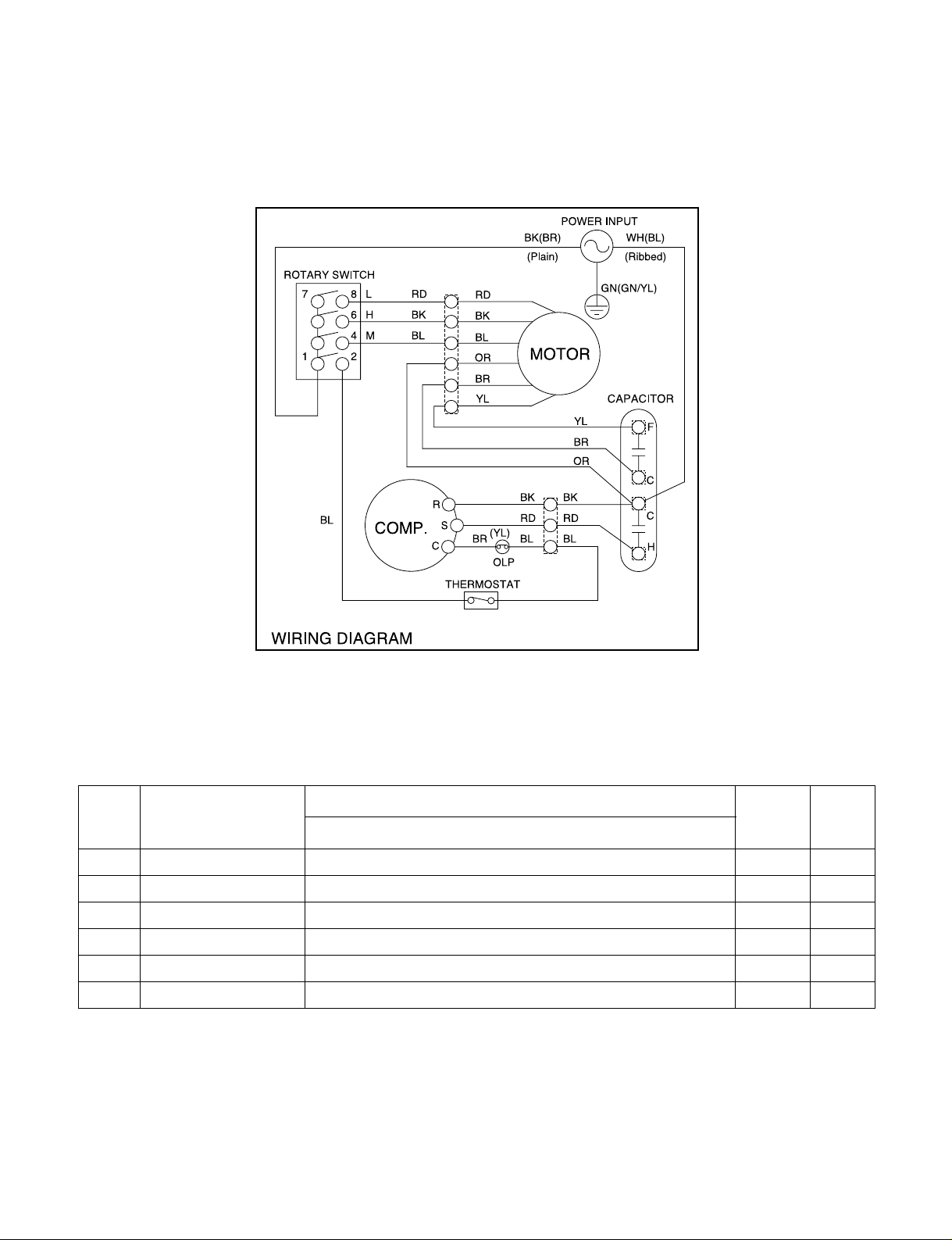
—22—
5.2 CIRCUIT DIAGRAM
■ MODEL : SV08A10A
SV08A10A
PART NO.
1 POWER CORD 67300005 1 S
2 ROTARY SWITCH 67300501 1 S
3 FAN MOTOR 67303014 1 S
4 CAPACITOR 67300712 1 S
5 THERMOSTAT 67300403 1 S
6 COMPRESSOR 67301612 1 S
LOCATION
NO.
DESCRIPTION
RE-
MARKS
Q'TY
PER SET
S: Service Parts
N: Non Service Parts
Page 23
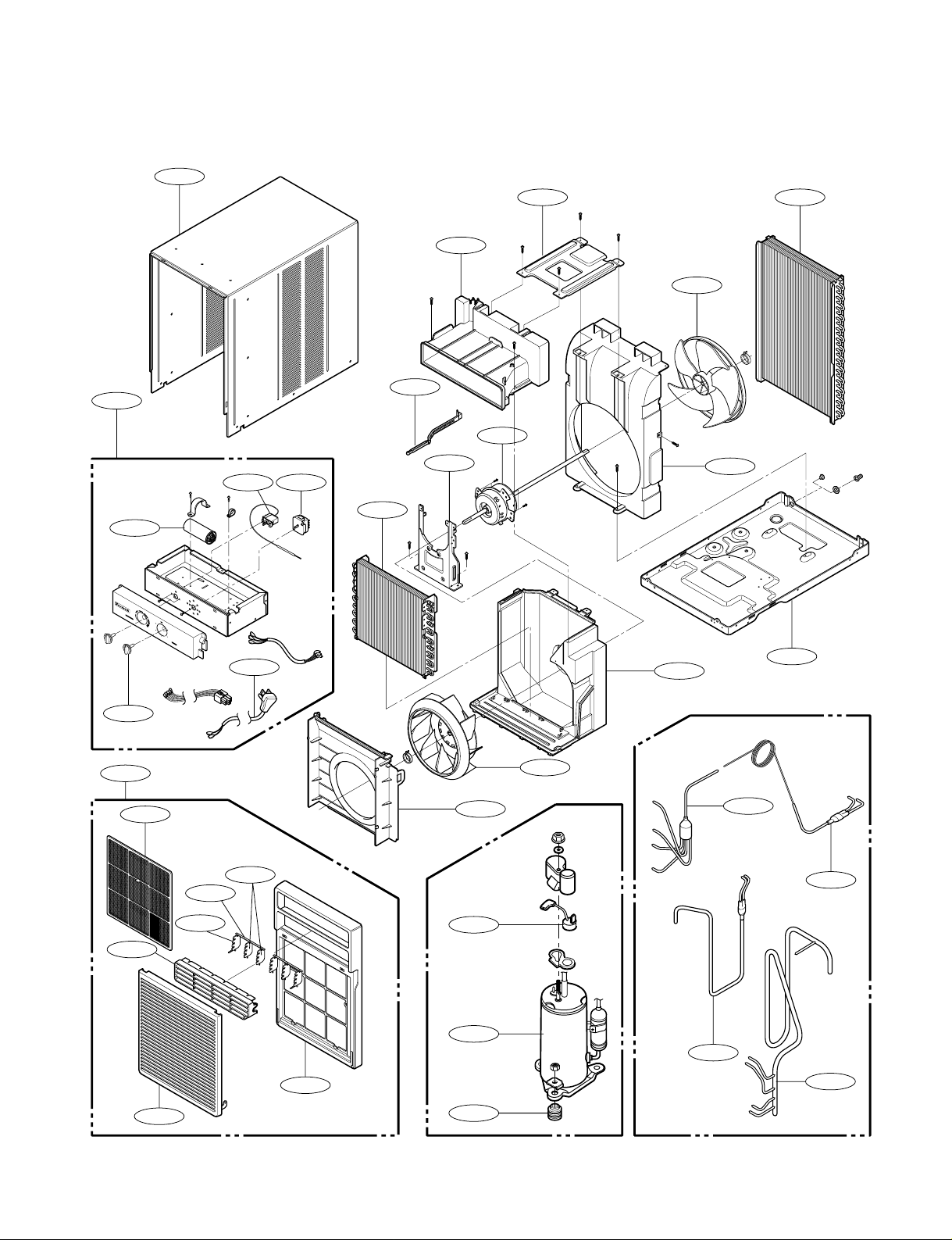
6. EXPLODED VIEW
—23—
554030148000
352390-2
349001
349600
346811
354210
152312
147581
145200
147582-2
135312
147582-1
135301
264110
269310 266003
249950
130910
359011
130410
552111
352113
352390-1
149980
W0CZZ
567502
554160
550140
349480
135303
359012
352115
35211A
149410
H
i
g
h
C
o
o
l
M
e
d
F
a
n
O
f
f
M
o
d
e
M
e
d
C
o
o
l
L
o
w
C
o
o
l
L
o
w
F
a
n
C
o
o
l
e
r
W
a
r
m
e
r
T
e
m
p
e
r
a
t
u
r
e
Page 24
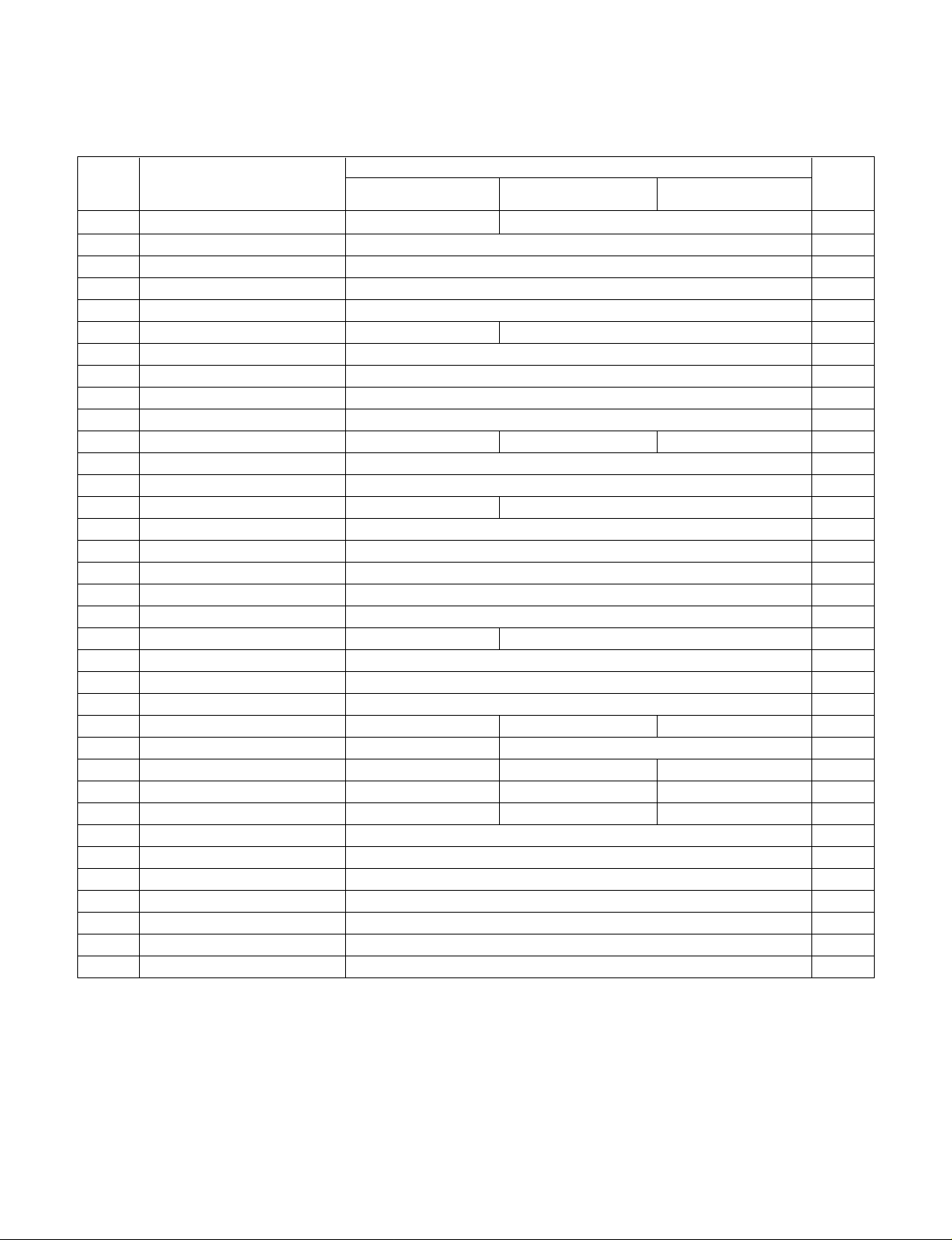
—24—
7. REPLACEMENT PARTS LIST
■ MODEL : SV08A10A, SV10A10A, SV12A10A
P/No
SV08A10A SV10A10A SV12A10A
130410 BASE ASSEMBLY, SINGLE 67302911 67302910 R
130910 CABINET ASSEMBLY, SINGLE 67303706 R
135303 GRILLE INLET 67306105 R
135312 GRILLE ASSEMBLY, FRONT 67306007 R
147581 VANE, HORIZONTAL 67306204 R
147582 VANE, VERTICAL 67306254 67306255 R
148000 BRACE 67303904 R
149410 KNOB ASSEMBLY 67304104 R
149980 SHROUD ASSEMBLY 67303109 R
152312 FILTER ASSEMBLY 67304305 R
264110 POWER CORD ASSEMBLY 67300005 67300006 67300007 R
266003 SWITCH, ROTARY 67300501 R
269310 THERMOSTAT ASSEMBLY 67300403 R
346811 MOTOR ASSEMBLY, SINGLE 67303014 67303015 R
349001 DAMPER 67303505 R
349480 ORIFICE 67303407 R
349600 MOUNT, MOTOR 67303608 R
352380 AIR GUIDE-LOWER ASSEMBLY 67302715 R
352390 AIR GUIDE ASSEMBLY-UPPER 67302714 R
354210 EVAPORATOR ASSEMBLY 67302411 67302412 R
359011 FAN ASSEMBLY AXIAL 67303206 R
359012 FAN ASSEMBLY, TURBO 67302610 R
550140 ISOLATOR, COMP 67301900 R
552111 TUBE ASSEMBLY, CAPILLARY 67302108 67302109 67302110 R
554030 CONDENSER ASSEMBLY 67303310 67303311 R
554160 COMPRESSOR 67301612 67301614 67301615 R
567502 O.L.P 67301410 67301409 67301407 R
W0CZZ CAPACITOR, DRAWING 67300712 67300709 67300713 R
731273 INSTALLATION KIT 67306306
237900 WINDOW, DISPLAY 67308101 R
132100 FRAME, PANEL 67308100 R
749740-1 GUIDE, UPPER 67304004 R
749740-2 GUIDE, FRAME 67306402 R
W4810-1 BRACKET 67303905 R
W4810 SUPPORT, BRACKET 67303906
LOCATION
No.
DESCRIPTION
REMARK
Page 25

—25—
MEMO
Page 26

—26—
MEMO
Page 27

Printed in the U.S.A
Post Office Box 1540 • 4200 N. Pan Am Expressway • San Antonio, Texas 78295-1540
• (210) 357-4400 • FAX (210) 357-4480
FRIEDRICH AIR CONDITIONING CO.
Visit our web site at www.friedrich.com
P/NO.: 3828A20190X
SV08 / SV10 / SV12 (01/05)
Use Factory Certified Parts...
 Loading...