

Page 1
Room Air Conditioners
AUTO
°F°C
AUTO
CONTINUOUS
AUTO
SYSTEM FAN MODE
SCHEDULE FAN SPEED
Window Installation Instructions
Standard Chassis Models
115-Volt:
208-230-Volt:
115-Volt:
208-230-Volt:
93001014_00
SS08, SS10, SS12, SS14
SS12, SM18,SM21
, SM15,
SL24, SL28, SL36
EQ08,YS10
ES12, ES16, YS12, EM18,
YM18, EM24, EL24, EL36, YL24
Page 2
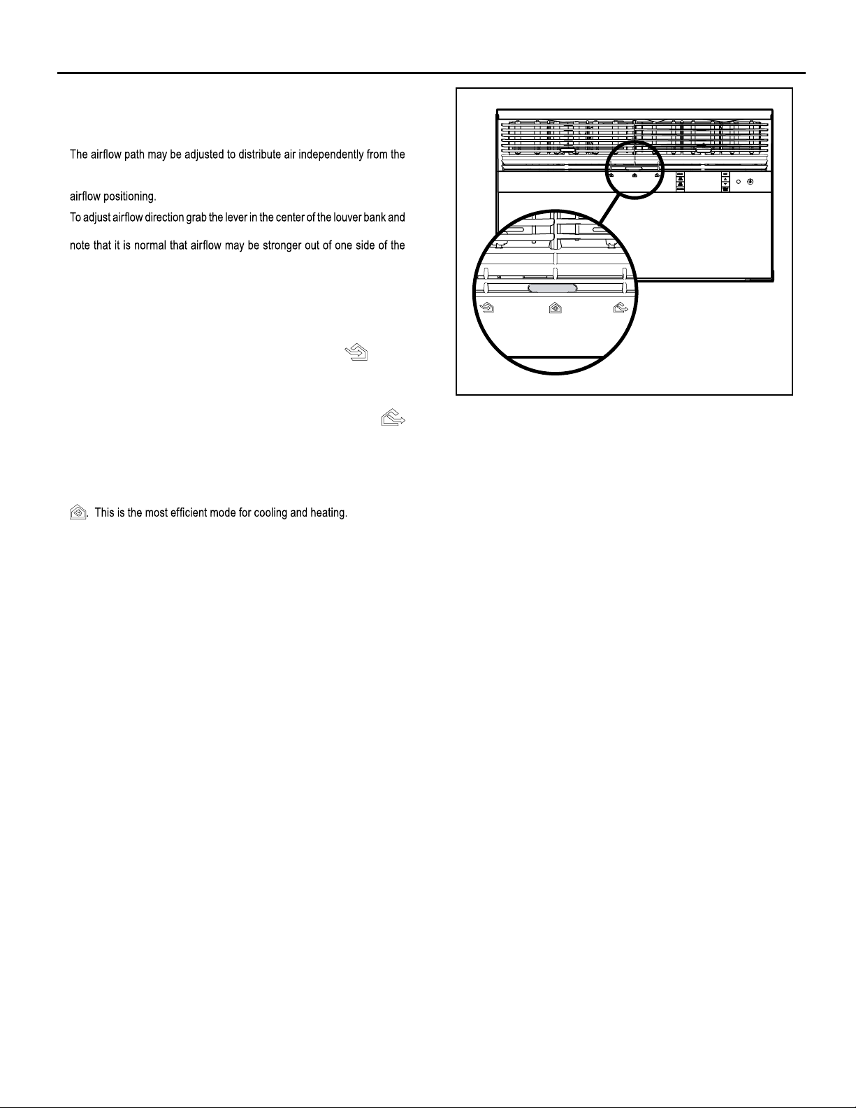
Airflow Selection and Adjustment
Air flow direction adjustment
left or right side of the discharge opening. Each of the banks of louvers
can be directed left, right, up or down in order to achieve the most optimum
move it in the direction that you would like the air to be directed. Please
louvers than the other.
Fresh air and exhaust control
Your air conditioner has the ability to bring fresh air into the room or exhaust
stale air out of the room. The control slide is found on the upper part of
the unit (See Figure 13).
TO BRING IN FRESH AIR – Move the lever to the Fresh Air
which allows outside air to enter the room. This is useful in fall and spring as
a means of bringing in fresh outside air when using FAN ONLY . It can also
be used in the summer with the compressor in the Cooling Mode if you wish.
TO EXHAUST INDOOR AIR – Move the lever to the Exhaust
position. This will allow stale air to be expelled to the outside of the dwelling.
This is especially handy in the spring or fall when indoor air tends to get
stale, or after a social gathering involving smokers, or to remove cooking
odors.
BEST PERFORMANCE – Move the lever to the Re-Circulate Position
position
Figure 13
FRR008
17
Page 3
Installation Instructions
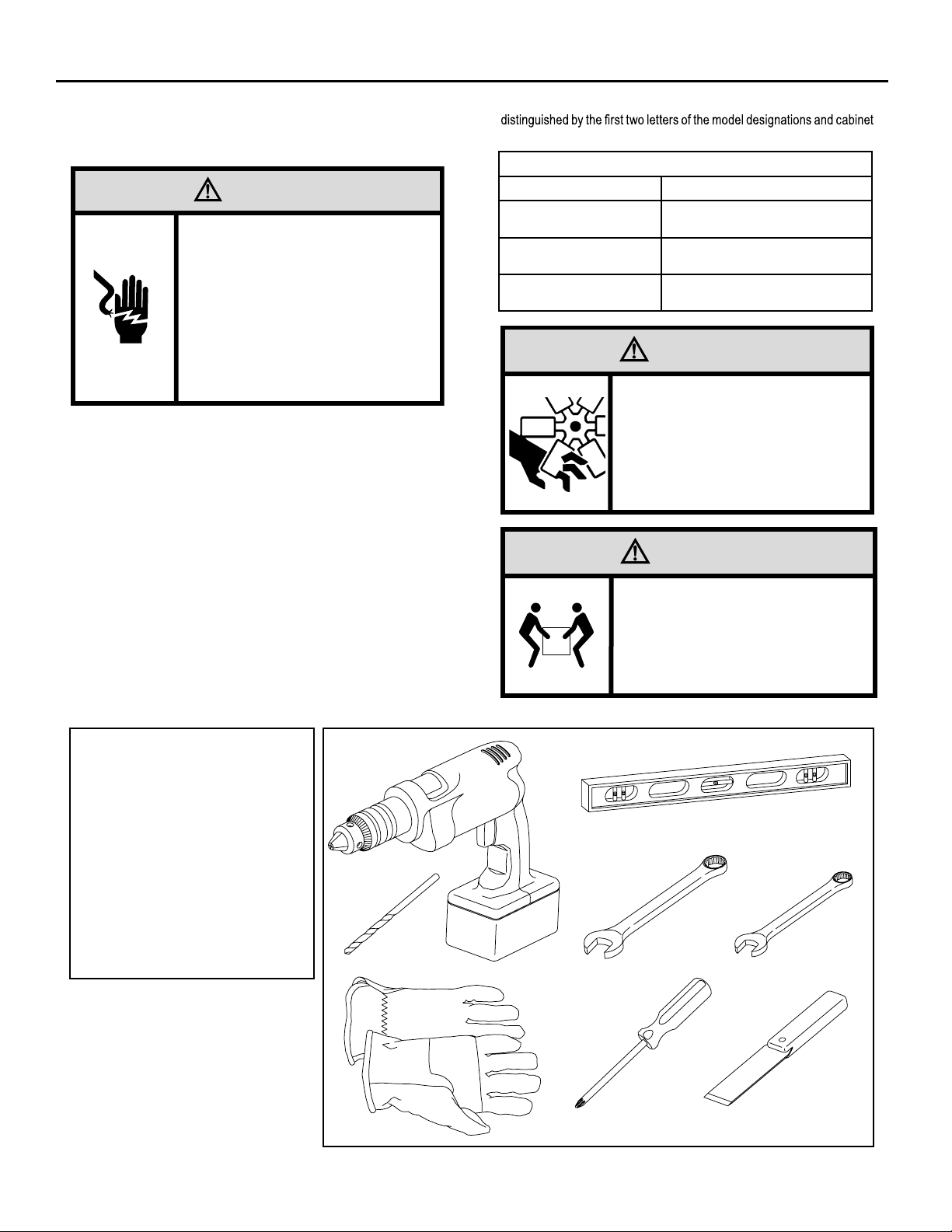
READ THIS FIRST! Electrical Requirements
WARNING
Electrical Shock Hazard
Make sure your electrical receptacle has the
same configuration as your air conditioner’s
plug. If different, consult a Licensed Electrician.
Do not use plug adapters.
Do not use an extension cord.
Do not remove ground prong.
Always plug into a grounded 3 prong oulet.
Failure to follow these instructions can result in
death, fire, or electrical shock.
IMPORTANT: Before you begin the actual installation of your air
Your air conditioner must be connected to a power source with the same
alternating current (A.C.) voltage and amperage as marked on the name
plate located on the chassis. Only A.C. can be used. Direct Current (D.C.)
cannot b
e used.
CIRCUIT PROTECTION – Use on single outlet circuit only. An overloaded
circuit will invariably cause malfunction or failure of an air conditioner,
therefore, it is necessary that the electrical protection is adequate. Due
to momentary high current demand when the air conditioner starts, use a
"TIME DELAY" fuse or a HACR type circuit breaker. Consult your dealer
or power company if in doubt.
fer to the electrical name plate located on the air conditioner chassis
Re
(See page 2) to determine the correct fuse or circuit breaker amperage
for your model (See Table 1 on Page 6 for electrical receptacle types).
The power cord has a plug with a grounding prong and a matching
receptacle is required.
The following instructions are for standard chassis model groups
sizes listed in Table 3.
Table 3
MODEL DESIGNATION CABINET SIZE (H x W x D)
SMALL CHASSIS - SS,
ES, YS
MEDIUM CHASSIS - SM,
EM, YM
LARGE CHA SS IS - SL,
EL, YL
15
15
⁄16" x 25 15⁄16" x 29" (405 mm x
660 mm x 737 mm)
15
17
⁄16" x 25 15⁄16" x 29" (455 mm x
660 mm x 737 mm)
3
20
⁄16" x 28" x 35 1⁄2" (513 mm x 711
mm x 851 mm)
WARNING
MOVING PARTS HAZARDS
* Do not operate unit out of sleeve
or with front grille removed.
.woleb noitamrofni eht dna sedoc lacirtcele lacol kcehc ,renoitidnoc
* Do not place hands in blower or
fan blade areas.
Failure to do so can result in
serious injury.
CAUTION
Excessive Weight Hazard
Use two or more people when
installing your air conditioner.
Failure to do so can result in
back or other injury.
Recommended Tools
1. Power Drill
2. 5/32" Drill Bit
3. Gloves
4. Carpenters Level
5. 5/16" Wrench
6. 1/4" Wrench
7. #2 Phillips Screw Driver
8. Putty Knife or (wood stir stick)
18
4
1
5/16
2
3
ITEMS NOT TO SCALE
5/16
1/4
1/4
65
87
Page 4
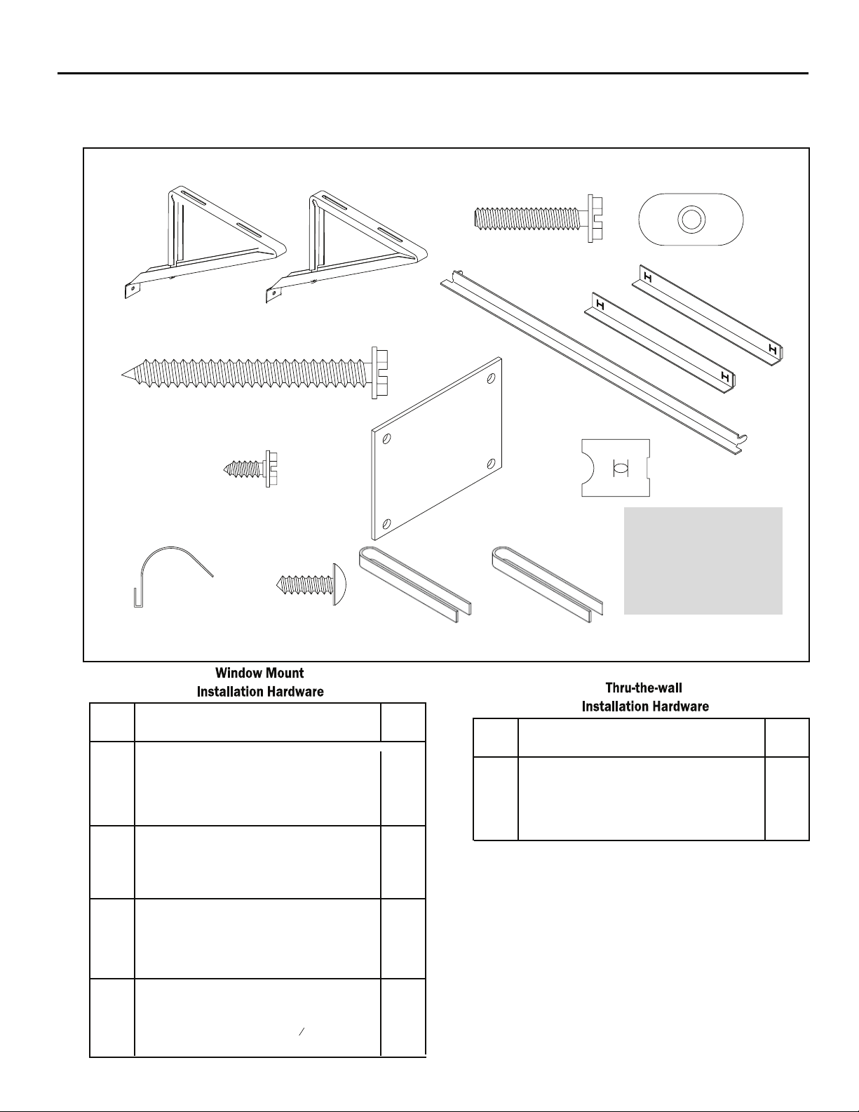
INSTALLATION HARDWARE AND ACCESSORY DETAIL
ITEM 10
ITEMS NOT TO SCALE
ITEM 1
ITEM 4
ITEM 7
ITEM 11
ITEM 2
ITEM 8
ITEM 12 ITEM 13
ITEM 3
ITEM 5 ITEM 6
ITEM 9
ITEM 14
FRR009
ITEM
DESCRIPTION QTY.
NO
SHELL MOUNTING PARTS
1
2
3
4
5
6
7
8
9
10
11
12 1
13
14
SUPPORT BRACKET
SCREW, 10-24 x 1" HEX HEAD
10-24 FLAT WELD NUT
SCREW, SHEET METAL #12 x 2"
WINGBOARD ANGLE MOUNTING
WINGBOARD ANGLE, TOP
WINGBOARD ANGLE, SIDE
SCREW, SHEET METAL #8 x
WINGBOARD MOUNTING PARTS
WINGBOARD (MASONITE)
"J" TYPE SPEED NUT
WINGBOARD CLIP (SPRING STEEL)
SCREW, #8 x ½" PHILLIPS TRUSS HD.
WINDOW SEALING
WINDOW SEAL GASKET (DARK FOAM)
CHASSIS SEAL GASKET (LIGHT FOAM)
R1 INSULATION PANEL (GREY FOAM)
3
8
"
ITEM
DESCRIPTION QTY.
NO
2
4
4
7
1
2
2
1
4
4
4
1
1
13
NOTE: Kühl + models do not come with window mounting
MOUNTING PARTS
4
SCREW, SHEET METAL #12A x 2”
CHASSIS SEAL GASKET (LIGHT FOAM)
components. When mounting a cooling and heating model
a window installation kit must be purchased separately.
KWIKS – For all ES and YS models.
KWIKM – For all EM and YM models.
KWIKL – For all EL and YL models.
7
1
19
Page 5
Standard Window Installation
Figure 15
NOTE: Hardware and accessories used during installation are shown
STEP 1. Remove the chassis Entrygard retainer by removing the far
on page 18. Each part will be referred as Item No.
right screw (See Figure 14), save this screw to reattach the
chassis retainer after installation (Step 12). Also, remove and
discard the two retainer screws and washers located at the
rear of the unit (See Figure 14).
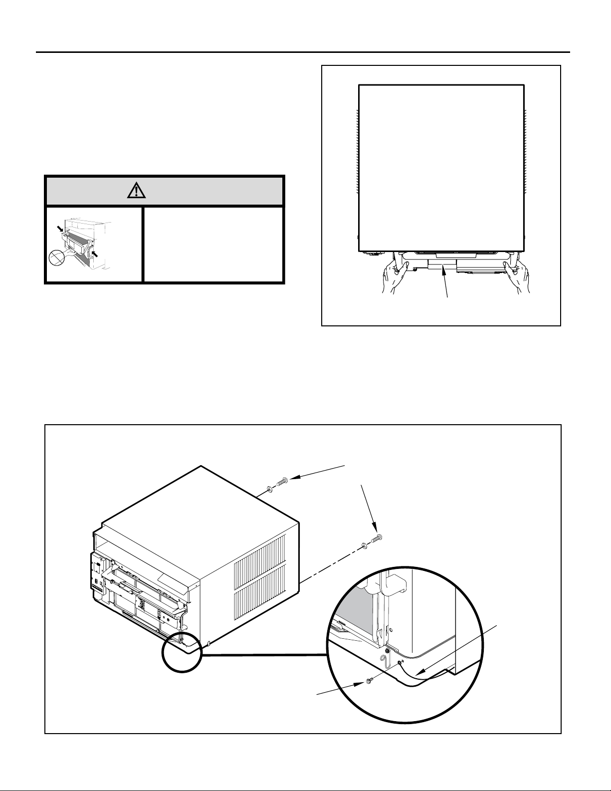
CAUTION
Handle Use
Use handle on both sides to
eldnaH esU
pull unit from sleeve.
snoitacoL
]sedis htob[
Do not push, pull or lift from
center of support.
STEP 2. Hold the cabinet stationary, then use the hand grips on both
STEP 3. Remove the large white foam blocks used to restrain the
ends of the control unit support bracket to pull the chassis out
of the cabinet (See Figure 15).
compressor during shipment (See Figure 16). Inspect base
pan for dislodged white foam blocks and remove. Do not
remove any other foam parts.
CONTROL UNIT
SUPPORT BRACKET
STEP 4. Anchor the side angles (Item 6) by engaging the tabs of the
lo
wer sill plate (See Figure 17, Detail B-2) with the loops of the
side angle. Engage the tabs of the top angle (Item 5) with the
top loops of the side angle (See Figure 17, Detail B-1). Install
two (2) screws (Item 7) to secure the top angle tabs and the
side angle to the cabinet (See Figure 17, Detail B-1).
FRR012
Figure 14
RETAINER SCREWS
AND WASHERS
ENTRYGARD
RETAINER
WIRE
FAR RIGHT
SCREW
20
FRR011
Page 6
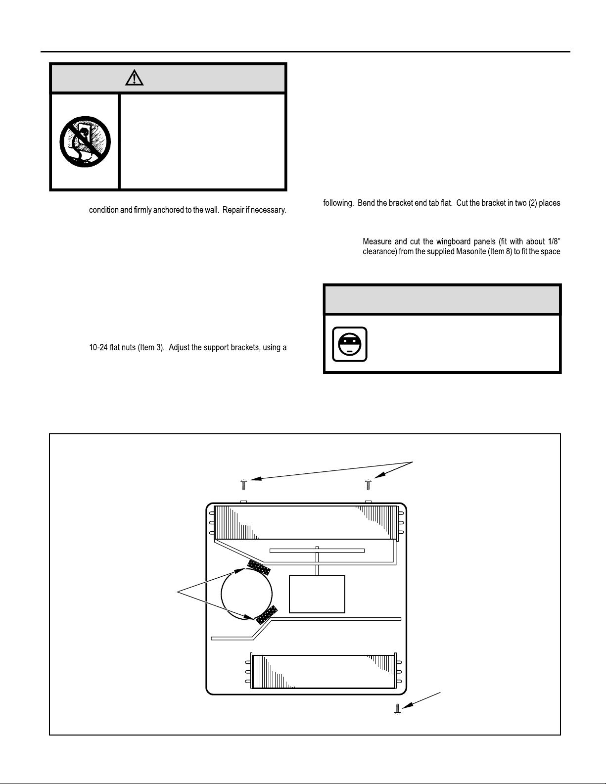
CAUTION
TOP VIEW OF UNIT
Remove Shipping Blocks
Prior to operating the unit remove
the foam shipping blocks.
Failure to do so may result in
damage to the unit which is not
covered by the manufacturer’s
warranty!
STEP 5. Check the window sill and frame to be sure they are in good
STEP 6. CABINET MOUNTING – Raise the lower window 1/4" more
STEP 7. OUTSIDE SUPPORT MOUNTING – Refer to Figures 19 and
Figure 16
than the height of the cabinet. Carefully slide the cabinet
through the opening until the lower sill plate channel rests
behind the window sill and the top angle rests against the
window (See Figure 18). Center the cabinet within the
opening. Drill three (3) 5/32" diameter pilot holes into window
sill using the holes in the cabinet sill plate as a guide. Install
th
ree (3) #12 x 2" long screws (Item 4) (See Figure 18).
20. Assemble the support brackets (Item 1) to the bottom of
the cabinet with four (4) 10-24 1” long screws (Item 2) and four
combination of the elongated holes of the bracket and different
hole locations in the cabinet, to bring the bottom support bracket
pads in contact with the wall. A 1" x 4" or 2" x 4" SPACER
SHOULD BE USED BETWEEN THE WALL AND SUPPORT
THE BRACKETS WHEN INSTALLED ON ALUMINUM OR
VINYL SIDING. Drill 5/32" diameter pilot holes and secure
the brackets to the wall with two (2) 12A x 2" long screws
(Item 4).
NOTE: DO NOT LEVEL the cabinet from front to back. Make sure there
Adjust the support brackets to provide an inside-to-outside slope for excess
condensation drainage (Refer to Standard Window Installation, Figures 19
through 23). Tighten all screws.
Alternate support method A: If you have a wide window sill which prevents
Using the elongated holes and different
Tighten all screws.
Alternate support method B: If the window ledge gap is narrow, try the
as shown in Figure 23. Bend the short piece so it will be vertical when
installed. Adjust the placement as required. Tighten all screws.
STEP 8.
is approximately 3/8” to 1/2” slope (1/8 to 1/4 bubble on level)
toward the outside of the house.
hole locations in the cabinet,
Make sure you include the depth of the window channel.
NOTICE
For YOUR security and safety, YOU must
provide a means of preventing the upper
part of the window from opening.
STEP 9. To assemble the wingboard panels, push on the "J" type speed
nuts (Item 9) and spring steel clips (Item 10) (See Figures 25)
on page 26. Secure each panel with two (2) screws (Item 11).
:gniwollof eht yrt ,22 erugiF ni nwohs sa stekcarb eht gnitnuom morf uoy
.)22 erugiF( thgiew s’tinu eht troppus ot tekcarb eht fo tnemecalp eht tes
.)42 erugiF( .tenibac dna slennahc edis wodniw eht neewteb
LEFT SIDE
REMOVE AND DISCARD
FOAM BLOCKS
COMPRESSOR
BACK
FAN MOTOR
EVAPORATOR COIL
FRONT
REMOVE AND DISCARD
SCREWS
RIGHT SIDE
REMOVE AND SAVE
SCREW FOR
RE-INSTALLATION
FRR045
21
Page 7

Figure 17
CABINET
#8 x 3/8” LONG SCREW
(ITEM 7) 2 REQUIRED
TOP ANGLE (ITEM 5)
TAB
Figure 18
DRILL (3) 5/32” DIA.
PILOT HOLES AND
INSTALL (3) #12 x 2”
CENTER
CABINET
IN WINDOW
SIDE TO SIDE
LONG SCREWS
(ITEM 4)
SILL PLATE
TAB
SIDE ANGLE
(ITEM 6)
2 REQUIRED
DETAIL B-2
DETAIL B-1
TAB
LOOP
FRR013
TOP ANGLE
(ITEM 5)
PULL WINDOW
SASH DOWN
BEHIND TOP
ANGLE
22
SIDE ANGLE
(ITEM 6)
WINDOW SILL
LOCATE SILL PLATE GUIDE CHANNEL
JUST BACK OF WINDOW SILL
FRR014
Page 8

Figure 19
3/8” SLOPE DOWN
#10-24 x 1” HEX HD.
SCREW (ITEM 2)
SUPPORT BRACKET
(ITEM 1)
SPACER SHOULD BE USED BETWEEN
WALL AND BRACKET WHEN INSTALLED
ON ALUMINUM OR VINYL SIDING.
Figure 20
#12 x 2” SCREW
(ITEM 4)
SUPPORT
BRACKET
(ITEM 1)
10-24 x FLAT WELD
NUT (ITEM 3)
FRR015
3/8” SLOPE DOWN
CONDENSER
AIR OUTLET
CONDENSER
AIR INLETS
#10-24 SCREW
#10-24 FLAT WELD NUT
#12 x 2” SHEET METAL
SCREW (ITEM 4)
SPACER SHOULD BE USED BETWEEN
WALL AND BRACKET WHEN INSTALLED
ON ALUMINUM OR VINYL SIDING.
FRR016
23
Page 9

Figure 21
STONE LEDGE
3/8” SLOPE DOWN
CONDENSER
AIR INLETS
#10-24 SCREW
#10-24 FLAT WELD NUT
#12 x 2” SHEET METAL
SCREW (ITEM 4)
SPACER
FRR017
Figure 22
3/8” SLOPE DOWN
#10-24 SCREW
STRAIGHTEN TAB TO LAY FLAT
ALONG THE BOTTOM RAIL OF
THE SHELL
#10-24 FLAT WELD NUT
SECURE THE LONGEST SIDE OF
THE BRACKET TO THE SHELL
ADJUST IN OR OUT TO REST
ON THE LEDGE
24
STONE LEDGE
FRR018
Page 10

Figure 23
3/8” SLOPE DOWN
Figure 24
#10-24 SCREW
#10-24 FLAT WELD NUT
STONE LEDGE
OUTSIDE WALL
DIMENSION “A”
CUT
HERE
CUT TO FIT DIMENSION “A”
AND BEND DOWN TO FORM
A VERTICAL LEG.
A
DISCARD
SHADED AREA
MEASURE DISTANCE “B” TO INSIDE OF THE
CHANNEL ON EACH SIDE.
FRR019
B
B
B
CUT HERE AND DISCARD CENTER WASTE
MATERIAL.
WINGBOARD
B
SUBTRACT 1/8” FROM DIMENSION “B” AND
MEASURE FROM THE EDGE OF THE WINGBOARD (ITEM 8), MARK, SCORE AND CUT
WITH APPROPRIATE CUTTING TOOL.
FRR020
25
Page 11

Figure 25
“J” TYPE SPEED NUT
(ITEM #9) 2 REQUIRED
CUT
WINGBOARD
PANEL
SPRING STEEL
CLIP (ITEM 10)
2 REQUIRED
3"
CUT EDGE
CENTER THE HOLE IN THE
SPEED NUT OVER THE SLOT
IN THE WINGBOARD PANEL
3"
SLIDE CLIP OVER CUT EDGE
OF WINGBOARD PANEL
ROTATED 90°
FRR021
2
Page 12

STEP
INSTALL THE R1 INSULATION PANEL – To
10.
minimize air leaks and ensure optimal insulation, install the
included R1 insulation panel. (14 in parts list) (See Figure
below A-C).
First, measure the width from one side of the cabinet/sleeve
(covering the side angles where the wingboard was just
secured) to the end of the wingboard. (See Figure A)
Next cut the R1 insulation panel to the measured width and
remove protective cover, exposing adhesive on back panel
(See Figure B)
Last, evenly apply the adhesive side of the panel across the
entire height and width from side angle to wingboard panel.
(See Figure C)
Repeat the steps above for the other wingboard panel.
STEP 11. INSTALL THE WINDOW SEALING GASKETS – Measure
the
and cut
Pull the window sash down behind the gasket. Measure and
cut the dark foam window seal gasket (Item 13) and install it
between the upper glass panel and the top part of the lower
window sash (Figure 29).
vinyl window seal gasket (grey color, Item 12) to
CAUTION
Excessive Weight Hazard
Use two or more people when
installing your air conditioner.
INSERT FOAM WINDOW
SEAL GASKET (ITEM 12)
I
Failure to do so can result in
back or other injury.
CAUTION
Cut/Sever
Although great care has been
taken to minimize sharp edges
in the construction of your unit,
use gloves or other hand
protection when handling unit
Failure to do so can result in minor
to moderate personal injury.
STEP 12 Carefully team lift the chassis and set it into the cabinet. Slide
NOTE:
the chassis stopping approximately 3" from full insertion. Insert
the chassis seal gasket (Item 14) one inch deep between the
A paint stir stick or ruler might be helpful here. Begin inserting
the gasket at either bottom corner and go up the side, across
the top, and down the opposite side. Then push the chassis
all the way into the cabinet.
If the chassis seal gasket is not installed or installed improperly,
the operation of the unit will be negatively affected. Operational
.82 egap no nwohs sa )92 erugiF eeS( tenibac eht dna sissahc
26
STEP 13. Reattach the entry guard chassis entry guard retainer wire with
the same screw retained in Step 1 (See Figure 14).
C
Page 13

FRR023
TOP OF CABINET
Figure 27Figure 26
PLACE WINGBOARD PANEL IN WINDOW JAM
TO COMPRESS THE SPRINGS INSIDE THE
RUNNERS, AND SWING THE WINGBOARD
PANELS INTO PLACE AS INDICATED BY THE
DASHED LINES.
WINDOW JAM
CLIP (ITEM 10)
SECTION A-A
INSERT VINYL WINDOW SEAL
GASKET OVER TOP ANGLE
TO WINGBOARD (ITEM 12)
B
B
LOWER WINDOW SASH
INSERT FOAM WINDOW
SEAL GASKET (ITEM 13)
A
SECURE THE SIDE WINGBOARD PANELS TO
THE SIDE ANGLES WITH FOUR (4) #8 x 1/2” LONG
SCREWS (ITEM 11), TWO ON EACH SIDE.
A
FRR022
VINYL
WINDOW
GASKET
TOP WINGBOARD ANGLE
SECTION B-B
27
Page 14

OPTIONAL: The factory assembles the supply cord so that it exits the left
SECTION A-A
SCALE 1 / 3
side of the unit at the bottom. At the consumer’s discretion,
To do this, route the supply cord to the right side. Pull the
supply cord taunt through the loops (Refer to Cord Routing
Change, Figure 30) and route the cord down.
Use Tool Provided
.tinu eht fo edis thgir eht tixe ot detuor eb nac droc ylppus eht
Please use the provided tool to attach the decorative front to the chassis.
Figure 28
STEP 1
To attach and prevent damage to the front grille align the
4.
cord notch over the cord and center the fresh air lever, then
align and tighten the four (4) captive screws as indicated by
the arrows in Figure 28. Before closing the front panel, be
sure the filter is in place. Make sure curtains do not block
the side air intakes.
STEP 15. Refer to the Control Panel Operation section for instructions.
STEP 1
6. You are now ready to control the comfort level of the room.
Figure 29
USE HAND TOOLS
DO NOT O VER T IGHTE N
B
LOCATION OF GRILLE
REMOVAL TOOL
FRR05 3
28
POWER CORD
CLIP
NOTE: WHEN INSTALLING THE CHASSIS
SEAL GASKET; BEGIN AT EITHER BOTTOM
CORNER AND GO UP THE SIDE & ACROSS
THE TOP & DOWN THE OPPOSITE SIDE.
CHASSIS SEAL
GASKET (ITEM 14)
FRR024
Page 15

Cord Routing Change
FRR054
Unplug unit.
STEP 17. Carefully pull out electrical control panel 1", but not all the way.
Figure 32
WARNING
Electrical Shock Hazard
Make sure your electrical receptacle has the
same configuration as your air conditioner’s
plug. If different, consult a Licensed Electrician.
Do not use plug adapters.
Do not use an extension cord.
Do not remove ground prong.
Always plug into a grounded 3 prong oulet.
Failure to follow these instructions can result in
death, fire, or electrical shock.
For convenience and optimum appearance the direction that the power cord
exits the unit may be changed from left to right by following the procedure
below. Select the exit location on the left or right based on proximity to
the power outlet.
Figure 30
ELECTRICAL
CONTROL PANEL
1 INCH
STEP 1
8. Pull electrical cord strain relief downward until free and rotate
90 degrees to the right.
Figure 33
FRR056
NOTE:
DECORATIVE FRONT REMOVED USE TOOL PROVIDED.
(SEE FIGURE 28 FOR LOCATION OF TOOL).
Remove 3 screws as shown from the electrical control panel. Save to
reinstall later.
Figure 31
ELECTRICAL CONTROL
PANEL SCREWS (3)
FRR055
90°
ELECTRICAL CORD
STRAIN RELIEF
STEP 1
9. Push electrical cord strain relief back upward into the electrical
control panel.
Figure 34
ENSURE THE ELECTRICAL CORD STRAIN RELIEF IS
FLUSH WITH THE TOP OF ELECTRICAL CONTROL PANEL
FRR057
FRR058
30
Page 16

STEP 20. Carefully push electrical control panel back into chassis.
Figure 35
ELECTRICAL
CONTROL PANEL
FRR059
STEP 2
2. If running power cord to the right of the unit install the cord
into the cord retainer clips along the bottom front of the unit.
Figure 37
CORD RETAINER
CLIPS
STEP 21. Reinstall the 3
screws removed earlier to secure electrical
control panel.
Figure 36
ELECTRICAL CONTROL PANEL SCREWS (3)
(RETAINED FROM STEP 1)
FRR060
FRONT
GRILLE
POWER
CORD
FRR061
31
Page 17

THIS PAGE INTENTIONALLY LEFT BLANK
29
Page 18

Friedrich Air Conditioning Co.
Post Office Box 1540 • San Antonio, Texas 78295-1540
4200 N. Pan Am Expressway • San Antonio, Texas 78218-5212
(210) 357-4400 • FAX (210) 357-4480
www.friedrich.com
Printed in Mexico
 Loading...