

Page 1
Room Air Conditioners
AUTO
°F°C
AUTO
CONTINUOUS
AUTO
SYSTEM FAN MODE
SCHEDULE FAN SPEED
Installation and Operation Manual
Standard Chassis Models
115-Volt:
208-230-Volt:
115-Volt:
208-230-Volt:
920-198-12 (3-11)
SS08, SS10, SS12, SS14, SM15
SS12, SS15, SM18, SM21
SM24, SL28, SL36
YS10
ES12, ES15, YS12, EM18
YM18, EM24, EL36, YL24
Page 2
THANK YOU!
your unit to assure quiet operation, the greatest circulation of cool, dry air, and the most economic operation.
AIR CONDITIONING CO.
SAN ANTONIO, TEXAS
ASSEMBLED IN MEXICO
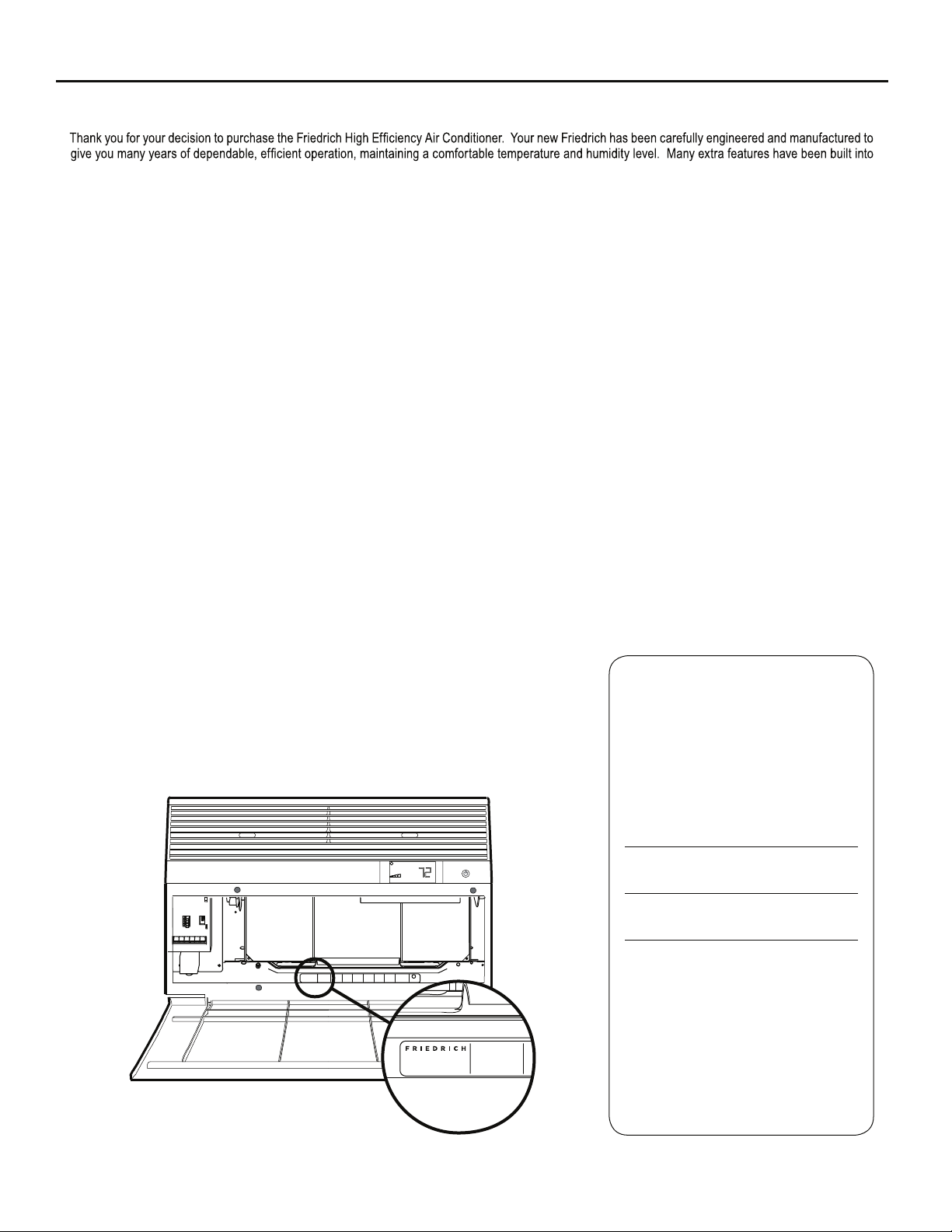
Register your air conditioner
Model information can be found on the name
plate behind the front cover.
Ple a s e complete an d mail the ow ner
registration card furnished with this product,
or register online at www.friedrich.com (USA
only). For your future convenience, record the
model information here.
MODEL NUMBER
SERIAL NUMBER
PURCHASE DATE
MODEL NUMBER
HEATING
REFRIGERANT
XXXXXXXXX
XXXXXXXXXX
VOLTS 115
COOLING
YS10M10A
60 HZ / 1 PH
BTH/HR 6500
SERIAL NUMBER
VOLTS MIN 108
EER 12.0
LICY00008
AMPS 8.0
FUSE PROTECTED
U
600 PSIG HS
XXXXXXXXX
CIRCUITS USE 15A
300 PSIG LS
XXXXXXXXXX
TIME DELAY FUSE
XXXXXXXXXX
L
X XX
XXXXX
XXXXXXXXXX
AIR CONDITIONING CO.
SAN ANTONIO, TEXAS
ASSEMBLED IN MEXICO
MODEL NUMBER
YS10M10A
SERIAL NUMBER
LICY00008
BTH/HR 6500
30.1 OZ R410A
EER 10.4
AMPS 7.0
2
Page 3
Table of Contents
Safety Precautions ................................................................................................................................................................................................................... 4
Unpacking Instructions............................................................................................................................................................................................................. 5
WARNING: Before Operating Your Unit ..................................................................................................................................................................................6
Standard Filter Cleaning / Installation Instructions ..................................................................................................................................................................7
Premium Carbon Filter Installation Instructions .......................................................................................................................................................................8
Control Panel Operation ........................................................................................................................................................................................................ 10
Add a Remote Thermostat ..................................................................................................................................................................................................... 14
Remote Thermostat Selection ...............................................................................................................................................................................................14
Remote Control Operation ..................................................................................................................................................................................................... 15
Remote Effectiveness ............................................................................................................................................................................................................ 15
.......................................................................................................................................................................................... 17
Installation Instructions .......................................................................................................................................................................................................... 18
Standard Window Installation ................................................................................................................................................................................................20
Cord Routing Change ............................................................................................................................................................................................................30
Through-the-Wall Installation ................................................................................................................................................................................................. 32
Programmable Thermostat ....................................................................................................................................................................................................36
Final Inspection & Start-up Checklist..................................................................................................................................................................................... 38
Routine Maintenance ............................................................................................................................................................................................................. 39
Service and Assistance .........................................................................................................................................................................................................39
Available Accessories ............................................................................................................................................................................................................ 39
Troubleshooting Tips .............................................................................................................................................................................................................. 40
Addendum 1 ........................................................................................................................................................................................................................... 42
3
Page 4
Safety Precautions
We have provided many important safety messages in this manual and on your appliance. Always read and obey all
safety messages.
WARNING
CAUTION
All safety messages will tell you what the potential hazard is, tell you how to reduce the chance of injury, and tell you
what will happen if the instructions are not followed.
Your safety and the safety of others are very important.
This is a safety Alert symbol.
This symbol alerts you to potential hazards that can kill or hurt you and others.
All safety messages will follow the safety alert symbol with the word “WARNING”
or “CAUTION”. These words mean:
Indicates a hazard which, if not avoided, can result in severe personal injury or
death and damage to product or other property.
Indicates a hazard which, if not avoided, can result in personal injury and
damage to product or other property.
NOTICE
Indicates property damage can occur if instructions are not followed.
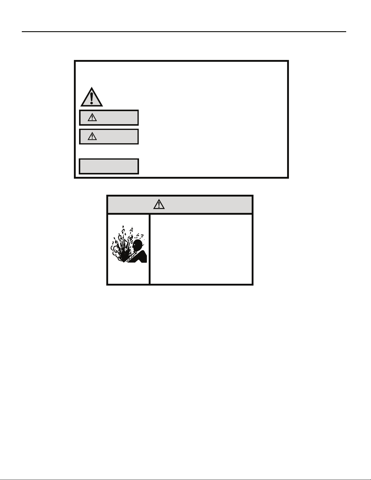
WARNING
Refrigeration system
under high pressure
Do not puncture, heat, expose to flame or
incinerate.
Only certified refrigeration technicians should
service this equipment.
R410A systems operate at higher pressures
than R22 equipment. Appropriate safe
service and handling practices must be used.
Only use gauge sets designed for use with
R410A. Do not use standard R22 gauge sets.
4
Page 5
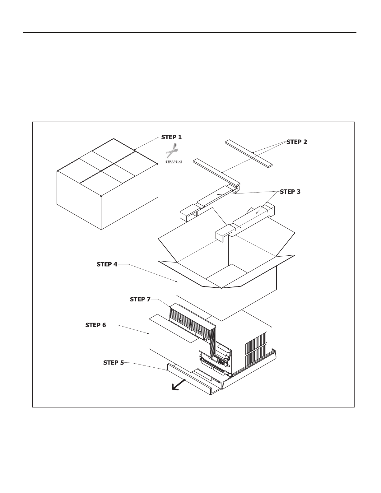
Unpacking Instructions
STEP 5. Slide the foam front support forward
STEP 1. Cut all 4 packing straps.
STEP 2. Remove wooden shipping bar dividers.
STEP 3. Remove top foam pads.
STEP 4. Slowly remove outer box, careful not to loosen decorative front.
STEP 6. Carefully lift decorative front box from foam front support
STEP 7. Remove decorative front and set safely aside
5
Page 6
WARNING: Before Operating Your Unit
WARNING
Electrical Shock Hazard
Make sure your electrical receptacle has the
same configuration as your air conditioner’s
plug. If different, consult a Licensed Electrician.
Do not use plug adapters.
Do not use an extension cord.
Do not remove ground prong.
Always plug into a grounded 3 prong oulet.
Failure to follow these instructions can result in
death, fire, or electrical shock.
Make sure the wiring is adequate for your unit.
If you have fuses, they should be of the time delay type. Before you install
or relocate this unit, be sure that the amperage rating of the circuit breaker
or time delay fuse does not exceed the amp rating listed in Table 1.
DO NOT use an extension cord.
The cord provided will carry the proper amount of electrical power to the
unit; an extension cord may not.
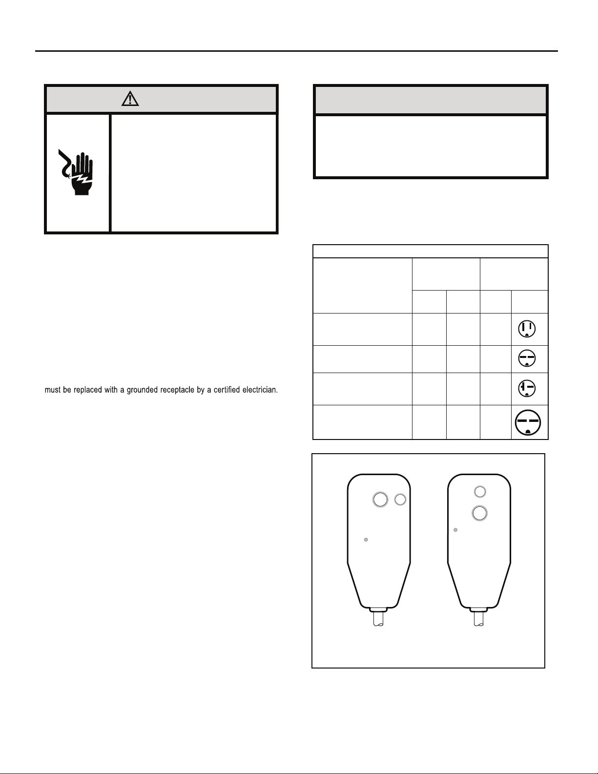
Make sure that the receptacle is compatible with
the air conditioner cord plug provided.
Proper grounding must be maintained at all times. Two prong receptacles
The grounded receptacle should meet all national and local codes and
ordinances. You must use the three prong plug furnished with the air
conditioner. Under no circumstances should you remove the ground
prong from the plug.
Test the power cord
All Friedrich room air conditioners are shipped from the factory with a
Leakage Current Detection Interrupter (LCDI) equipped power cord. The
LCDI device on the end
for cord connected air conditioners.
To test your power supply cord:
1. Plug power supply cord into a grounded 3 prong outlet.
2. Press RESET (See Figure 1).
3. Press TEST, listen for click; the RESET button trips and pops out.
4. Press and release RESET (Listen for click; RESET button latches
and remains in). The power cord is ready for use.
of the cord meets the UL and NEC requirements
NOTICE
Do not use the LCDI device as an ON/OFF switch.
Failure to adhere to this precaution may cause
premature equipment malfunction.
Once plugged in, the unit will operate normally without the need to reset
the LCDI device. If the LCDI device fails to trip when tested or if the power
supply cord is damaged, it must be replaced with a new power supply cord
from the manufacturer. Contact our Technical Assistance Line at (800)
541-6645. To expedite service, please have your model number available.
Table 1.
SS08, SS10
SS12, SS14
YS10
, SM15
SS12, SS15
SM18, SM21
SM24
, SL28
ES12, ES15
YS12
SL36, EM18
EM24,
EL36
YM18, YL24
Figure 1
MODEL
RESET
WARNING
TEST BEFORE EACH USE
1. PRESS RESET BUTTON
2. PLUG LCDI INTO POWER
RECEPTACLE
3. PRESS TEST BUTTON,
RESET BUTTON SHOULD
POP UP
4. PRESS TEST BUTTON,
FOR USE
DO NOT USE IF ABOVE TEST
FAILS
WHEN GREEN LIGHT IS ON
IT IS WORKING PROPERLY
CIRCUIT RATING
OR TIME DELAY
AMP VOLT
15 125 5-15R
15 250 6-15R
20 250 6-20R
30 250 6-30R
TEST
FUSE
TEST BEFORE EACH USE
1. PRESS RESET BUTTON
2. PLUG LCDI INTO POWER
RECEPTACLE
3. PRESS TEST BUTTON,
RESET BUTTON SHOULD
POP UP
4. PRESS TEST BUTTON,
FOR USE
DO NOT USE IF ABOVE TEST
FAILS
WHEN GREEN LIGHT IS ON
IT IS WORKING PROPERLY
REQUIRED
WALL
RECEPTACLE
NEMA
NO.
TEST
RESET
WARNING
15/20A LCDI Device 30A LCDI Device
FRR001
6
Page 7
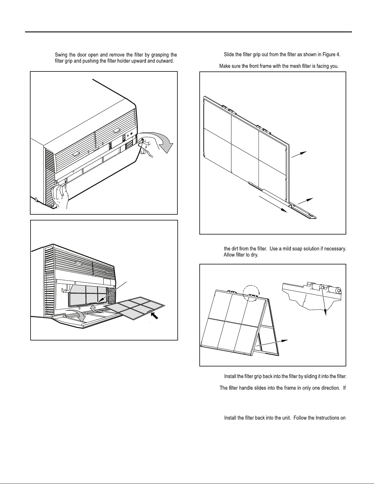
Standard Filter Cleaning / Installation Instructions
STEP 1.
Figure 2
FRR071
STEP 2.
NOTE:
Figure 4
FILTER
FILTER
GRIP
Figure 3
FILTER
GRIP
HANDLE
FRR052
FRR047
STEP 3. Swing the front frame open. Clean the front frame by washing
Figure 5
A
TOP TAB
FRONT
FRAME WITH
STANDARD
MESH FILTER
FRR048
STEP 4.
NOTE:
the tab in the frame stops the handle from sliding in, slide the
handle from the other direction. Do not force the handle into
the frame.
STEP 5.
the inside of the front door.
7
Page 8
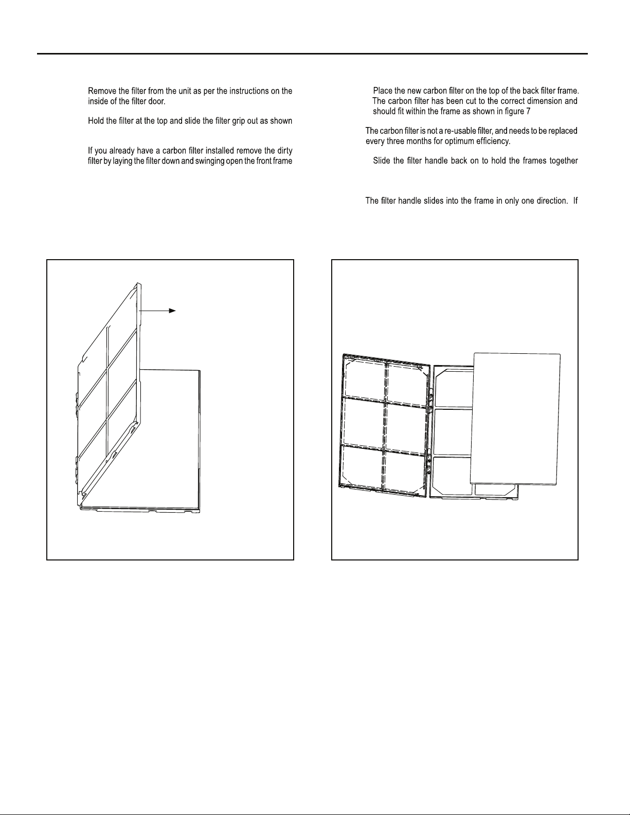
Premium Carbon Filter Installation Instructions
STEP 1.
STEP 4.
STEP 2.
in Figure 4.
STEP 3.
as shown in Figure 6.
NOTE: Make sure the frame with the mesh is facing towards you.
Figure 6
FRONT FRAME WITH
MESH FILTER
NOTE:
STEP 5.
and slide the assembly into the unit as per the instructions
on the door.
NOTE:
the tab in the frame stops the handle from sliding in, slide the
handle from the other direction. Do not force the handle into
the frame.
Figure 7
FRR051FRR050
8
Page 9

THIS PAGE INTENTIONALLY LEFT BLANK
9
Page 10
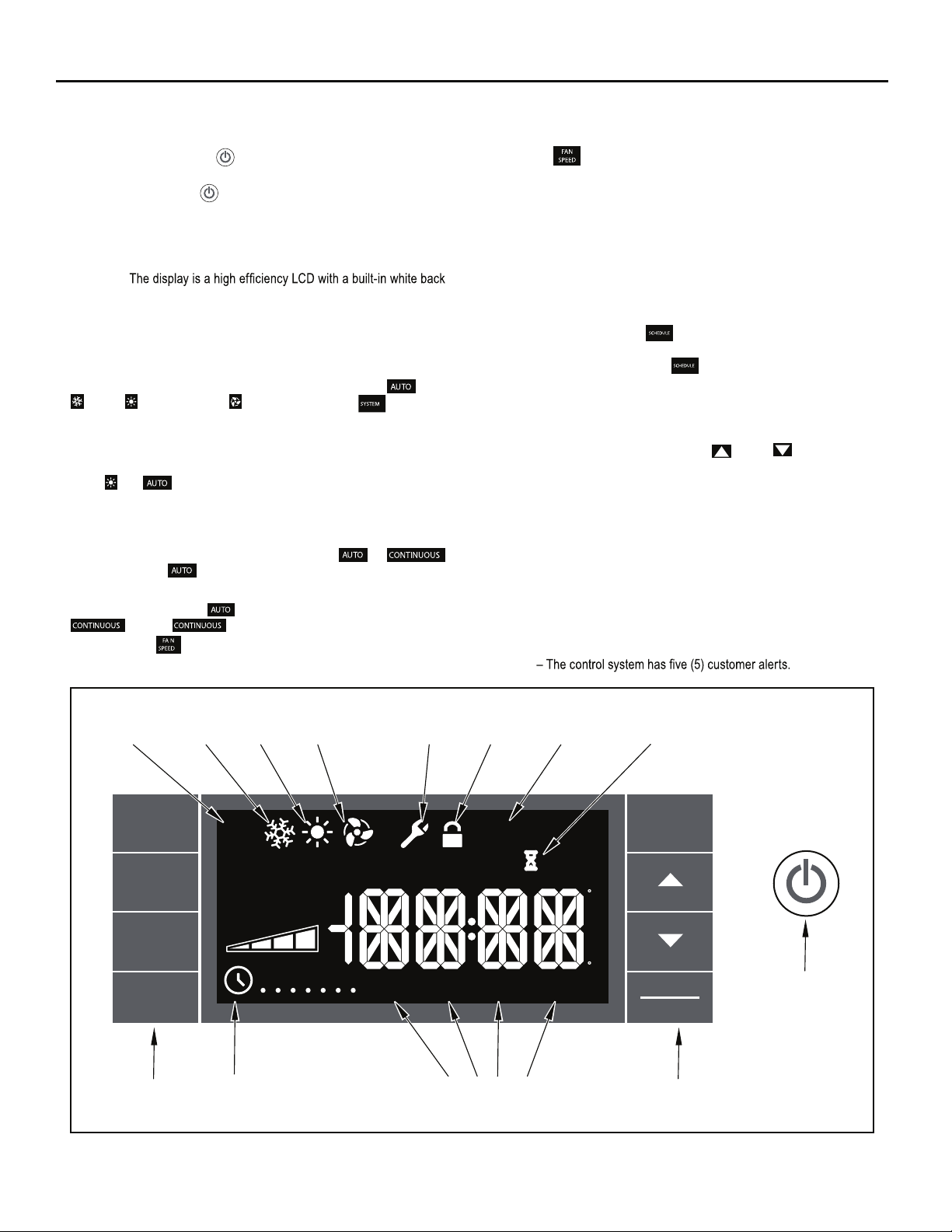
Control Panel Operation
Let’s check out how to control your air conditioner. On the control panel,
just to the left of the POWER , is a liquid crystal display (LCD). All of the
control panel function buttons and mode icons can be viewed in Figure 8.
Power On – Press the
power button will illuminate to indicate the power is on. The backlight on
the power switch will automatically dim to 20% intensity after 15 seconds
of inactivity. The remote control can also be used to turn power ON / OFF
(See Remote Control).
Display –
light. The back light has an automatic two (2) step dim function. After 15
seconds of inactivity, the display dims to 20% intensity. After an additional
120 seconds, the display switches off. Touching buttons will automatically
bring the display to full brightness.
There are four control push buttons on each side of the display.
S
YSTEM Button – Allows the user to sequentially select,
, HEAT , and FAN ONLY operation. Press the button and
the display advances to the next mode. A new icon appears. At the same
time, the mode displays for two (2) seconds, then returns the display to
the temperature set point for modes other than FAN. Note that when the
heating function is not available, the system will automatically skip the
HEAT
and modes.
NOTE: After the compressor stops the fan will continue to operate for 30
seconds.
FAN MODE Button – Selects between automatic
operation. In the mode, the fan only turns on and off when the
compressor operates or the heat function is enabled.
In the FAN ONLY Mode,
. In the mode, fans speed is determined by your
selection on the button.
button to turn on the air conditioner. The
Cool
or
is not available. The display indicates
FAN SPEED Button .sdeeps naf neewteb tceles yllaitneuqes ot desU –
Depending on your model, you can select between LOW, MED, HIGH,
When the
button is pressed, the fan speed is temporarily displayed
in the display window, plus a fan speed icon (triangle) changes to indicate
the new speed level. W
hen auto is selected,
fan speed automatically varies
depending on the set temperature on the control panel and the actual
room temperature. Let me explain. Say for example you’re working in
your garage and you need to open the big door for several minutes. The
air conditioner will sense a wide difference between the set temperature
and the actual room temperature when this occurs the system fan speed
increases to MAX. The fan speed decreases (in step) as the temperature
difference decreases. When the set point temperature is reached the FAN
speed returns to the original setting.
SCHEDULE Button – The
button turns the schedule function on
and off. The current day of the week is indicated as a dot underneath
the day symbol. Pressing the
button a second time turns the
schedule function off. The schedule function comes preprogrammed with
recommended energy savings values (Addendum 1). The values may
be changed through the schedule program function (See Programmable
Thermostat).
UP and DOWN arrows – Pressing either
(UP) or (DOWN) button
changes the desired room temperature. The factory preset lower and
upper limits are 60° F (16° C) and 99° F (37° C). These buttons are also
used to navigate between function options when using the User Menu or
Maintenance Mode.
BACK Button .detceles neeb sah meti unem a retfa desu si nottub sihT –
It takes the user back to the previous menu level.
DISPLAY/ENTER Button – This button is used in conjunction with User
menu and Maintenance Mode operation to select items.
This button may also be used alternately to
RATURE
and TIME. If the display is left inactive for 10 seconds it will
display the ROOM TEMPE-
reset to the TEMPERATURE SET POINT.
Alerts
.)sledom sulp looc ro LY ,LE ,LS no ton gnittes xaM .OTUA dna XAM dna
Figure 8
AUTO
MODE
SYSTEM
FAN
MODE
FAN
COOL
MODE
HEAT
MODE
AUTO
AUTO
CONTINUOUS
AUTO
FAN
ONLY
MODE
MAINTENANCE
REQUIRED
OUTDOOR TEMP
% RH
SPEED
M
SCHEDULE
BUTTONS BUTTONS
SCHEDULE
ON/OFF
T W
T F S
S
WAKE
AWAY
SCHEDULE
FRONT
PANEL
LOCK
CHECK
FILTERONOFF
HEAT ->
RETURN NIGHT
PERIODS
FILTER
MAINTENANCE
EXIT
RESET
<- COOLROOM TEMP SET POINT
F
A
M
P
M
C
WAIT
BACK
DISPLAY
ENTER
POWER
FRR002
10
Page 11
CHECK FILTER
appears on screen. The word “ ” appears next to the .nottub
The alert is issued when the fan run .sruoh 005 naht retaerg si emit
This alert may be reset by the user (Refer to Special Functions, Filter Reset).
Maintenance Required – When maintenance is required, a service icon
appears on screen. This icon will not be dismissed until maintenance
has been performed. If the service icon
the icon .noitidnoc lamronba na desnes sah metsys eht ybdnats no si
is established the service icon goes away.
Wait – The WAIT icon .evitca si tuokcol rosserpmoc eht nehw setanimulli
Whenever the compressor shuts off, system pressures must be allowed
to equalize. At this time, an internal timer begins a count-down from up to
240 seconds. If a demand for heat or cool occurs during this count-down
the WAIT icon
displays letting you know that the compressor will not
operate until the count-down has completed. This timer prevents damage
to the unit if it tries to start too quickly after it stops running. Normally the
WAIT icon
is off. Once the timer has cleared, the air conditioner will
heat or cool based on the temperature setting. Electric heat is not affected
by this timer.
Protection Alert (Freeze) – If the room freeze protection is active, the
display indicates this by showing Room Freeze Protection "FRZ". Once
temperature is less than 40° F (4° C), and the air conditioner is equipped with
electric heat, the room freeze protection will activate. The air conditioner
will run high fan and electric heat until the room temperature reaches
46° F (8° C). Pressing the
Low Battery – When the battery is low a warning display
button delays the freeze protection function
will be
inserted before other messages such as “COOL”. If the Low Battery
alert is on, the battery in the control unit must be changed. Refer
to the changing the battery procedure. Once the battery is changed, the
alert message will go off. Refer to Troubleshooting Tips. Under normal
conditions the battery life should be greater than 7 years.
Special Functions
Panel Lock
inadvertent operation. To lock the front panel, press and hold the
buttons for three (3) seconds. A double beep indicates your mode
change was successful and a icon appears on the display. To unlock
the display, press and hold the + .sdnoces )3( eerht rof snottub
The icon will no longer be visible.
Filter Reset –
and holding the button for three (3) seconds. A beep indicates the
system timer was reset and the icon and the word "
no longer be visible.
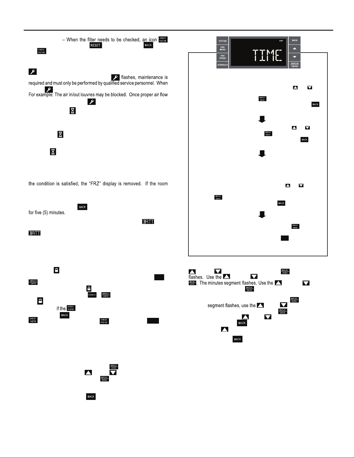
User Menu Functions – The User Menu Functions allows you to change
the following selections: Set TIME, 12/24 Hour Clock Format, BEEP ON /
OFF, DIM ON / OFF, Emergency Heat (EMHT) ON / OFF, Auto BAND Adjust,
F/ C Select, FRZ ON / OFF, the Automatic Temperature Sensing Feature
and Temp Offset.
To enter the User Menu, press and hold
selection appears. Use the (UP) or (DOWN) buttons to scroll
through the User Menu. Press the button to enter the displayed
function. If left inactive for 15 minutes the User Menu display will no longer
be visible and it returns to normal operation mode display. To manually
exit the User Menu, press the
– The front panel push buttons can be locked to prevent
SCHEDULE
icon displays, the timer may be reset by pressing
" will
RESE T
for 3 seconds, the TIME
button.
+
The hour digits flash first. The user presses the or
to change the hours. To change AM-PM, the hours must be
advanced 12 hours. Press the key to change to the
minutes. To exit the selection process, user presses the
key which will go to the time screen.
The minutes digits flash. The user presses the or
to change the minutes. Press the key to change the days.
To exit the selection process, the user presses the key
which will go to the time screen.
The dot underneath the days of the week begins to blink to
indicate which day it is. If the user has not set the date before,
the dot starts on Monday. If the user is making a correction to
previously set information the dot appears under whichever
day the unit thinks it is. The user can press or to move
the dot left or right (respectively) along the week. The user
presses to loop back to the hours setting. To exit the
selection process, the user presses the key which will go
to the time screen.
Tuesday has been selected. The user presses to loop
back to the hours setting. To exit the selection process and
accept the changes, the user presses the key which will go
to the time screen.
BACK
FRR062
Time Setting – When in the User Menu, on the Control Panel, use the
(UP) and (DOWN) to select TIME. Push , the hours segment
(UP) and hsup neht ,ruoh eht tes ot )NWOD(
(UP) and
to set the minutes, then push
.
NOTE: If the AM or PM indicator is incorrect, push
(DOWN)
until the hours
(UP) or (DOWN) to advance
the hour segment 12 hours, then push
displays. Use the
day. Press the
Press
(UP) to go to the next menu 1224.
NOTE: Pressing the
(UP) or (DOWN) to select the current
key to
save and go back to the TIME screen.
button again will exit the user menu function
. The day of the week
mode. Or simply leave the control inactive for 15 seconds and
the control will return back to normal operation.
11
Page 12
SYSTEM
FAN
MODE
FAN
SPEED
SCHEDULE
BACK
EXIT
DISPLAY
ENTER
SYSTEM
FAN
MODE
FAN
SPEED
SCHEDULE
BACK
EXIT
DISPLAY
ENTER
User presses or to toggle the format between 12HR and
24HR display. To exit the selection process and accept the
change, press the key.
FRR063
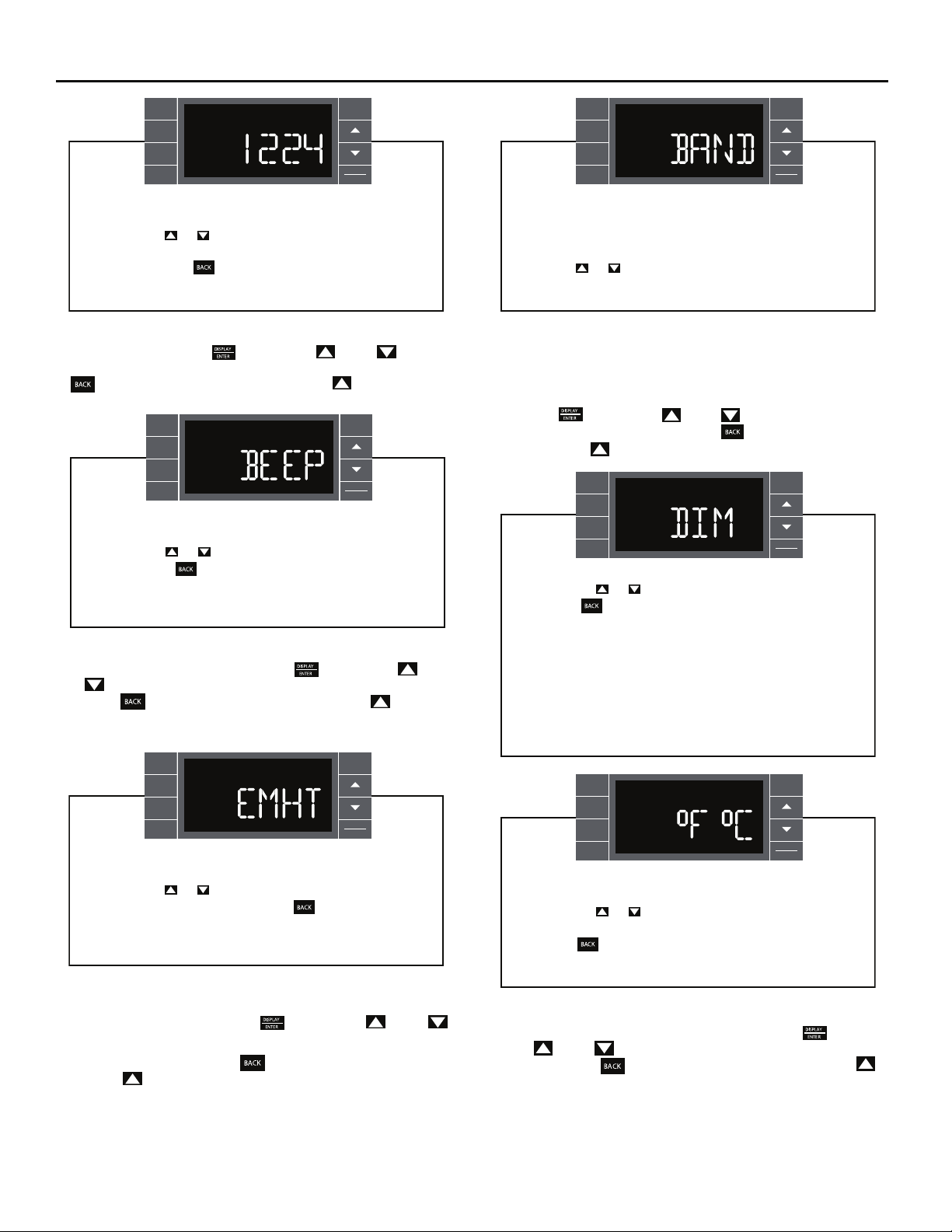
Clock Type – You may select between a 12 hr and 24 hr clock. When
1224 is displayed press the
key then press (UP) or (DOWN)
to toggle between 12 hr and 24 hr clock. To accept the change, press the
key to return to the 1224 screen. Press the (UP) to go to the
next menu BEEP.
BACK
SYSTEM
FAN
MODE
FAN
SPEED
SCHEDULE
EXIT
DISPLAY
ENTER
User presses or to toggle between Beep On and Beep
Off. Press the key to accept the change and exit the
selection process.
FRR064
Audible Alerts – You can select to have the control beep when entering
menus.
When BEEP is displayed press the
or
(DOWN) to toggle between ON and OFF. To accept the change,
press the
key to return to the BEEP screen. Press the (UP) to go
key then press (UP)
to the next menu EMHT on Kühl+ models or F C for Kühl models.
The menu allows the user to adjust the minimum spread
between the Auto Cool set point and the Auto Heat set point.
Press the or key to adjust. The adjust range is 3 to 10.
FRR066
Auto Changeover ‘Dead Band’ – A buffer Zone between heating and
cooling in which no conditioning occurs. For Kühl+ models with the auto
changeover feature you can select the temperature band between heating
and cooling. From the factory the band is set at 3° F (-16° C). The band is
adjustable from 3° F (-16° C) to 10° F (-12° C). When BAND is displayed
press the key then press (UP) or (DOWN) to toggle between
3 and 10. To accept the change, press the key to return to the BAND
screen. Press the (UP) to go to the next menu F C.
BACK
SYSTEM
FAN
MODE
FAN
SPEED
SCHEDULE
User presses or to select between AUTO, DM 20, OFF.
Press the key to accept the change and exit the
selection process.
The Dim Auto automatically dims the display and then turns it
off after a period of time. The Dim 20 setting behavior is similar
to AUTO, but prevents the display from turning off. Minimum
brightness is 20%. The Dim Off setting forces the display to run
at full brightness.
EXIT
DISPLAY
ENTER
BACK
SYSTEM
FAN
MODE
FAN
SPEED
SCHEDULE
EXIT
DISPLAY
ENTER
User presses or to toggle between Emergency Heat On
and Emergency Heat Off. Press the key to accept the
change and exit the selection process.
FRR065
Emergency Heat – The Kühl+ heat pump models (YS, YM, YL) have
a special feature that is designed to keep the unit providing heat.
When EMHT is displayed press the
key then press (UP) or
.FFO dna NO neewteb elggot ot )NWOD(
To accept the change, press the
Press the
(UP) to go to the next menu BAND
.
In the unlikely event of a compressor failure, the heat pump unit may be
switched to operate in the electric heat mode only until repairs can be
made.
12
FRR067
BACK
SYSTEM
FAN
MODE
FAN
SPEED
SCHEDULE
EXIT
DISPLAY
ENTER
User presses or at the same time to toggle between
Fahrenheit or Celsius as their temperature unit of choice.
Press the key to accept the change and exit the selection
process.
FRR068
Fahrenheit / Celsius Selection – You may select between displaying
temperature in F or C. When F C is displayed press the
key then
press (UP) or (DOWN) to toggle between F and C. To accept the
.neercs THME eht ot nruter ot yek
change, press the key to return to the F C screen. Press the
(UP) to go to the next menu FRZ.
Page 13
BACK
SYSTEM
FAN
MODE
FAN
SPEED
SCHEDULE
EXIT
DISPLAY
ENTER
User presses or to select between Freeze Protection On
& Freeze Protection Off. Press the key to accept the
change and exit the selection process.
FRR069
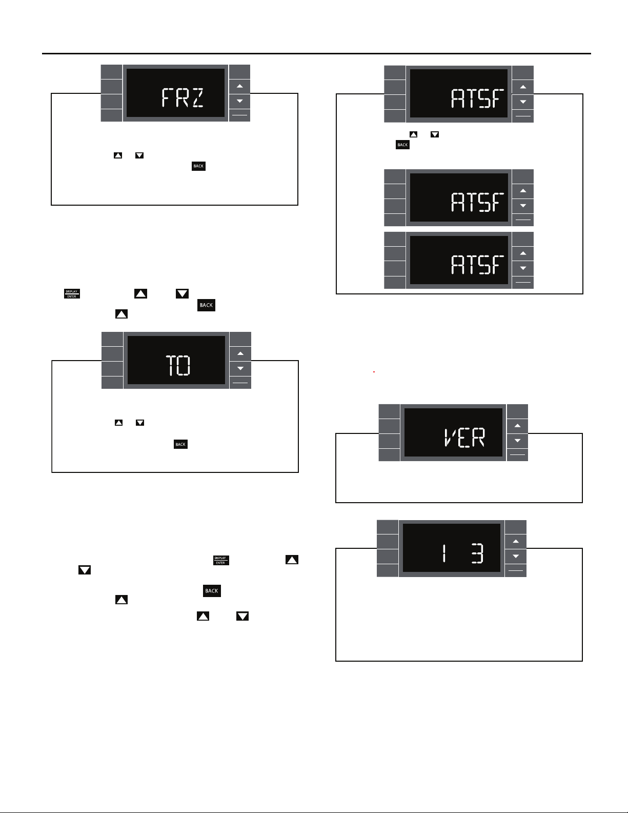
Freeze Protection – The Kühl+ models have a special feature that is
designed to keep the interior space above freezing by energizing the
electric heater anytime the indoor room temperature f . )C °4( F °04 ot slla
With the freeze protection feature turned on, when the unit senses the
indoor temperature fall to 40° F (4° C) the unit will run the heater and high
fan until the space reaches 46° F (8° C) W
the
key then press (UP) or (DOWN) to toggle between ON
hen FRZ is displayed press
and OFF. To accept the change, press the key to return to the FRZ
screen. Press the
(UP) to go to the next menu TO.
SYSTEM
FAN
MODE
FAN
SPEED
SCHEDULE
BACK
EXIT
DISPLAY
ENTER
BACK
SYSTEM
FAN
MODE
FAN
SPEED
SCHEDULE
F
F
Y
R
EXIT
DISPLAY
ENTER
FRR072
User presses or to select between ATSF On or Off.
Press the key to accept the change and exit the
selection process.
BACK
SYSTEM
FAN
MODE
FAN
SPEED
SCHEDULE
SYSTEM
FAN
MODE
FAN
SPEED
SCHEDULE
EXIT
OFF
DISPLAY
ENTER
BACK
EXITON
DISPLAY
ENTER
FRR073
FRR074
Automatic Temperature Sampling Feature - The automatic temperature
sampling feature maintains a balanced temperature throughout the room
by circulating the air for 30 seconds once every 9 minutes that the unit is
not running and set to cooling or heating mode. By circulating the air the
unit can detect hot or cold area in the room and operate the unit to cool or
warm the room as necessary. This function is only available when the fan
mode is set to ‘AUTO’ and in COOL or HEAT mode. (Heating function only
available on Kuhl+ units)
User presses or to increment/decrement the temperature
offset (TO) for the room temperature sensor. (Maximum offset
= +/- 8 degrees F). Press the key to accept the change
and exit the selection process
FRR070
Temperature Offset – In some cases the built in thermostat on the unit
may not display the temperature as it is felt in the room. This can be caused
by many things including the size of the unit, the heat load on the room or
other factors. Friedrich allows you to select the appropriate temperature
offset to make the temperature readout as accurate as possible for your
application. In
many cases the factory 0° F (-18° C) offset will provide
an accurate temperature readout. To change the offset follow these
instructions. When TO is displayed press the
(UP) or
(DOWN) to toggle between 0° F (-18° C) and 8° F (-13 . )C °
key then press
In most instances an offset from 0° F (-18° C) to 2° F (-17° C) is all that is
necessary. To accept the change, press the
screen. Press the
(UP) to go to the next menu TIME.
key to return to the TO
You may cycle through the menus using the (UP) or (DOWN) keys
to access any of the menus.
BACK
SYSTEM
FAN
MODE
FAN
SPEED
SCHEDULE
EXIT
Y
DISPLAY
ENTER
For display only. No user selectable options.
SYSTEM
FAN
MODE
FAN
SPEED
SCHEDULE
F
F
BACK
EXIT
DISPLAY
ENTER
Firmware Version - When VER is displayed press Display /
Enter key. The firmware version is displayed as left digit
(Major) and right digit (Minor). This version number should be
used along with Model and Serial numbers for service.
FRR075
FRR076
13
Page 14
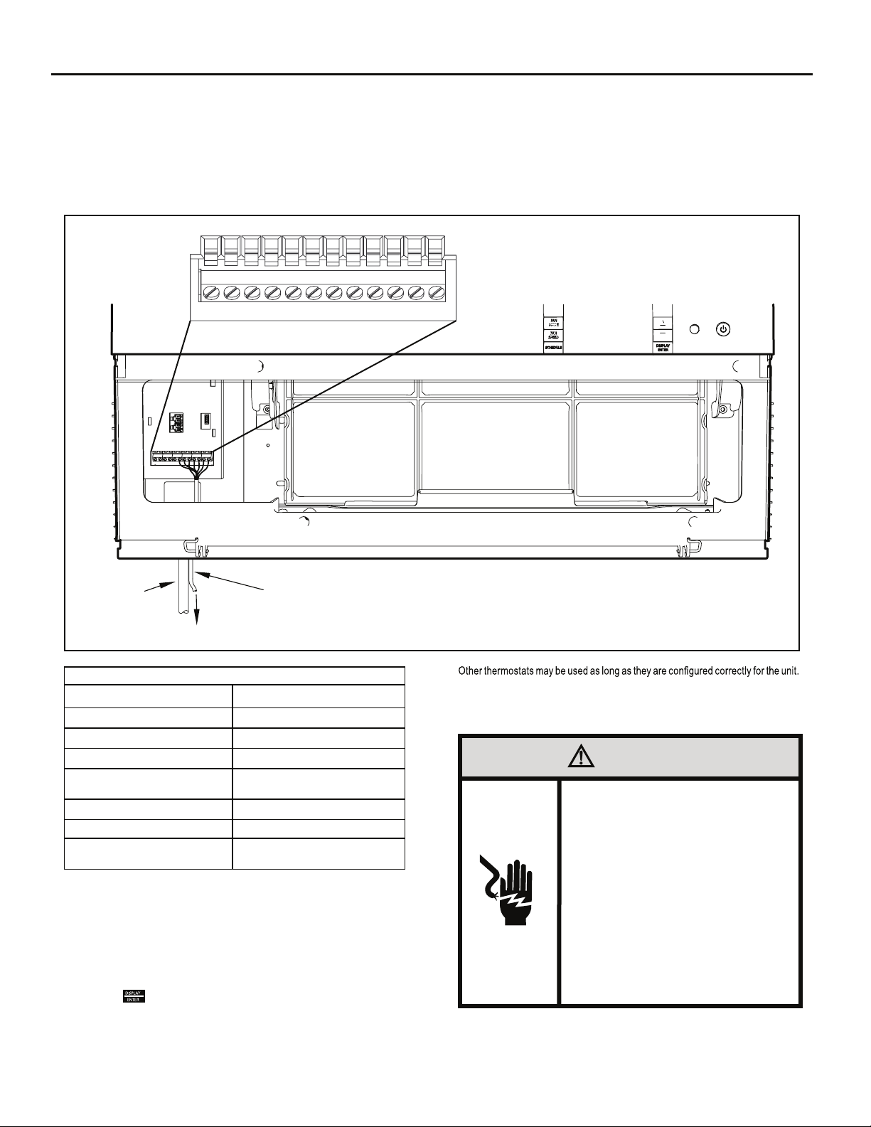
Add a Remote Thermostat
Remote Thermostat – An external thermostat may be added to the air
conditioner to provide remote temperature sensing and control. The
thermostat interface connector is located on the panel behind the front
grille. To enable the remote thermostat operation, remove the jumper
4. Changing modes on the remote thermostat will not illuminate the
Control Panel LCD.
Remote Thermostat Selection
Friedrich recommends the use of either the RT4 or RT5. The RT4 is a
digital display thermostat with single speed fan control. The RT5 features
a digital display, two fan speed selection, battery backup and backlight.
Figure 9
POWER
CORD
THERMOSTAT CONNECTOR
FP
F2
D2
F1
THERMOSTAT WIRE ROUTING USE #18
AWG COLORED THERMOSTAT WIRE
GH
CD1
GL
B
Y
W
R
TO REMOTE THERMOSTAT
Table 2
Terminal Code
between terminals
Interface Definitions
C
GH
GL
B
Y
W
R
FP & F2
on the terminal block. Connect the thermostat
Wire Connection Function
Common Ground Terminal
Call for High Fan
Call for Low Fan
Call for Heat Pump Reversing Valve
Call for Compressor
Call for Heating
24V Power from Electronic Control to
Wall Thermostat
using Figure 9 and Table 2 as a guide.
If you connect an external thermostat, all Control Panel buttons will be
disabled with the following exception:
1. Maintenance commands (double button press & single button
extended press).
2. The
button for Freeze protection.
3. First Button pushed, illuminate the LCD.
FRR004
For cooling models a single stage cooling thermostat with C, R, G, Y terminals must
be used. For electric heat ‘E’ models a single stage heating and cooling thermostat
with C, R, G, Y, W terminals must be used. For heat pump ‘Y’ models a single
stage heating and cooling thermostat with C, R, G, Y, W, B terminals must be used.
CAUTION
It is the installer’s responsibility to
ensure that all control wiring
connections are made in accordance
with the installation instructions.
Improper connection of the thermostat
control wiring and/or tampering with
the unit’s internal wiring can void the
equipment warranty.
Failure to follow these instructions can
result in personal injury and damage to
product or other property.
14
Page 15
Remote Control Operation
Remote Control – Refer to Figures 11 and 12 during operation description.
Getting Started – Install two (2) AAA batteries in the battery compartment
located on the back of the unit.
Operation – The remote control should be within 25 feet of the air
conditioner for operation (Refer to Figure 10 for effectiveness). Press the
button to turn the remote on. The remote will automatically power off
after 15 seconds if the buttons are not being pressed. The remote must
be on to control the unit.
POWER Button – Turns remote and unit on and off.
SYSTEM Button – Allows the user to sequentially select,
HEAT , and FAN ONLY operation. When the button is pressed, the
Note that when the heating function is not available, the system will
automatically skip the HEAT and AUTO modes.
FAN MODE Button – Selects between automatic (
operation. In the AUTO mode, the fan only turns on and off when the
compressor operates or the heat function is enabled.
NOTE: AUTO is not available in the FAN ONLY Mode, the display
indicates
. In the mode, fan speed is
determined by your selection on the button.
Figure 10
Cool ,
) or
FAN SPEED Button – Used to sequentially select new fan speed, plus
AUTO operation. When the
FAN
button is pressed, the fan speed is
SPEED
temporarily displayed in the display window, plus a fan speed icon (triangle)
changes to indicate the new speed level. Fan speed automatically varies
depending on the set temperature on the control panel and the actual
room temperature. Let me explain. Say for example you’re working in
your garage and you need to open the big door for several minutes. Since
there is a big difference between your set temperature and the actual room
temperature the system fan speed increases to MAX. It remains at this
speed until the room temperature matches the set temperature.
SCHEDULE
SCHEDULE Button
off. Pressing the
– The
SCHEDULE
button a second time turns the schedule function
button turns the schedule function on and
off. Only the schedule icon will be displayed.
.egassem yalpsid a aiv detceles neeb sah edom hcihw setacidni yalpsid
button changes the desired room temperature. The factory preset lower
UP and DOWN Arrows – Pressing either the
(UP) or (DOWN)
and upper limits are 60° F (16° C) and 99° F (37° C). These buttons are
also used to navigate between function options when using the User Menu
or Maintenance Mode.
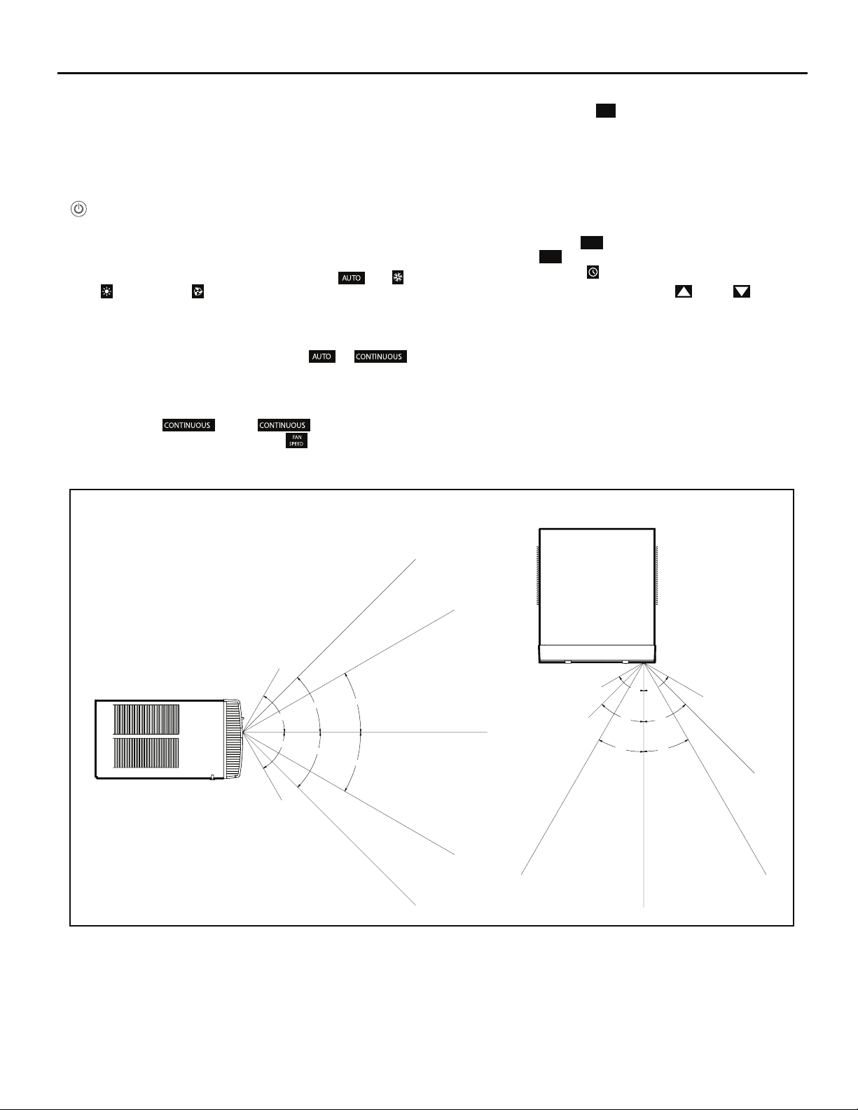
Remote Effectiveness
Hand Held Remote – Has an operating range of up to 25 ft. The infrared
remote control signal must have a clear path to transmit the command to
the air conditioning unit. The remote signal has some ability to "bounce"
off of walls and furniture similar to a television remote control. The diagram
below shows the typical operating range of the control in a standard room
with 8 ft high ceilings.
TOP VIEW
SIDE VIEW
25ft
25ft
7.5ft
45°
60°
60°
8ft
30°
25ft
45°
30°
25ft
25ft
25ft
4ft
8ft
60°
60°
45°
45°
30°
30°
25ft
6ft
16ft
25ft
FRR046
15
Page 16
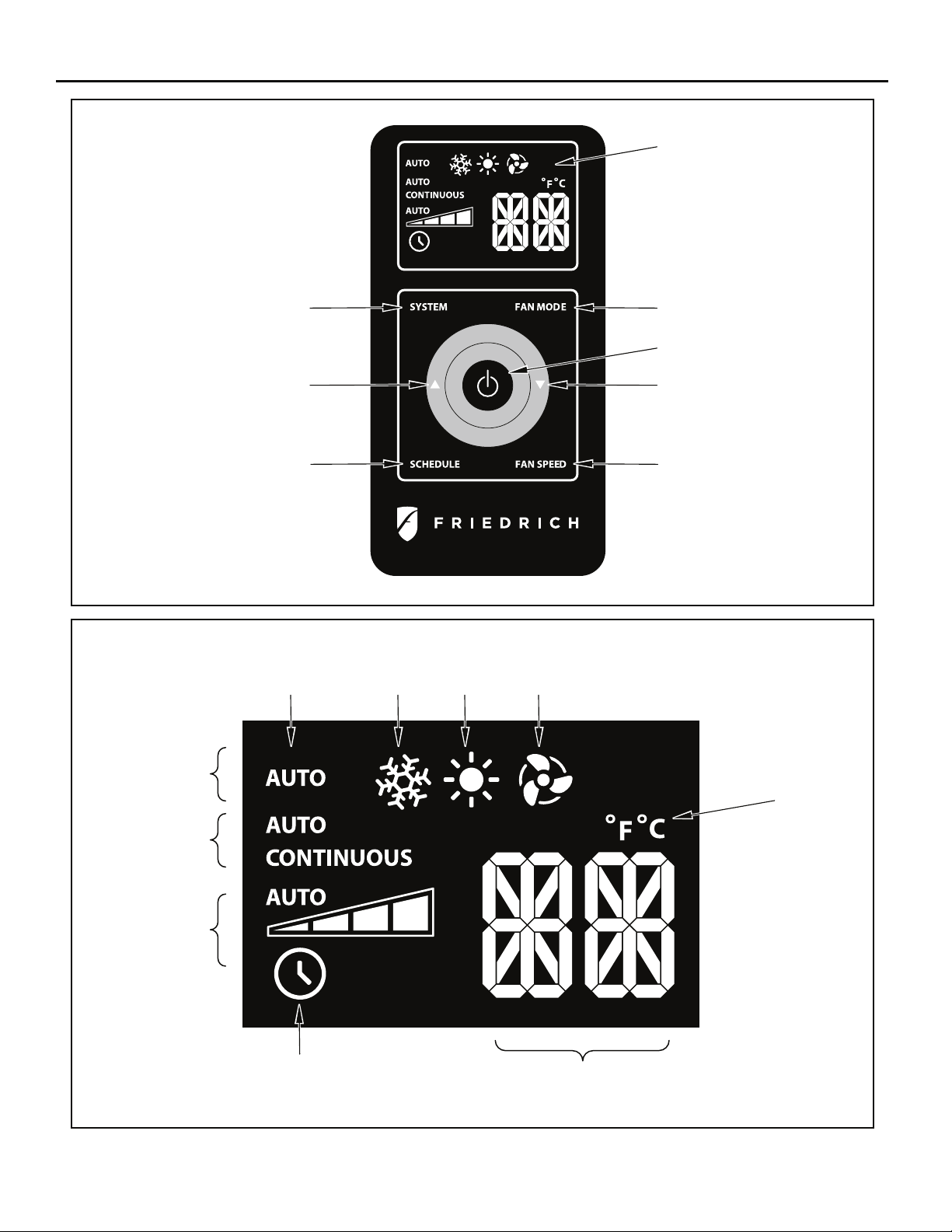
Figure 11
DISPLAY
Figure 12
SYSTEM
TEMPERATURE
UP
SCHEDULE
AUTO
ICON
COOL
ICON
HEAT
ICON
FAN MODE
POWER
TEMPERATURE
DOWN
FAN SPEED
FRR005
FAN ONLY
ICON
16
SYSTEM
MODE
FAN
MODE
FAN
SPEED
SCHEDULE
ICON
°F / °C
ICONs
2 X 16 SEGMENT
DISPLAY
FRR006
Page 17
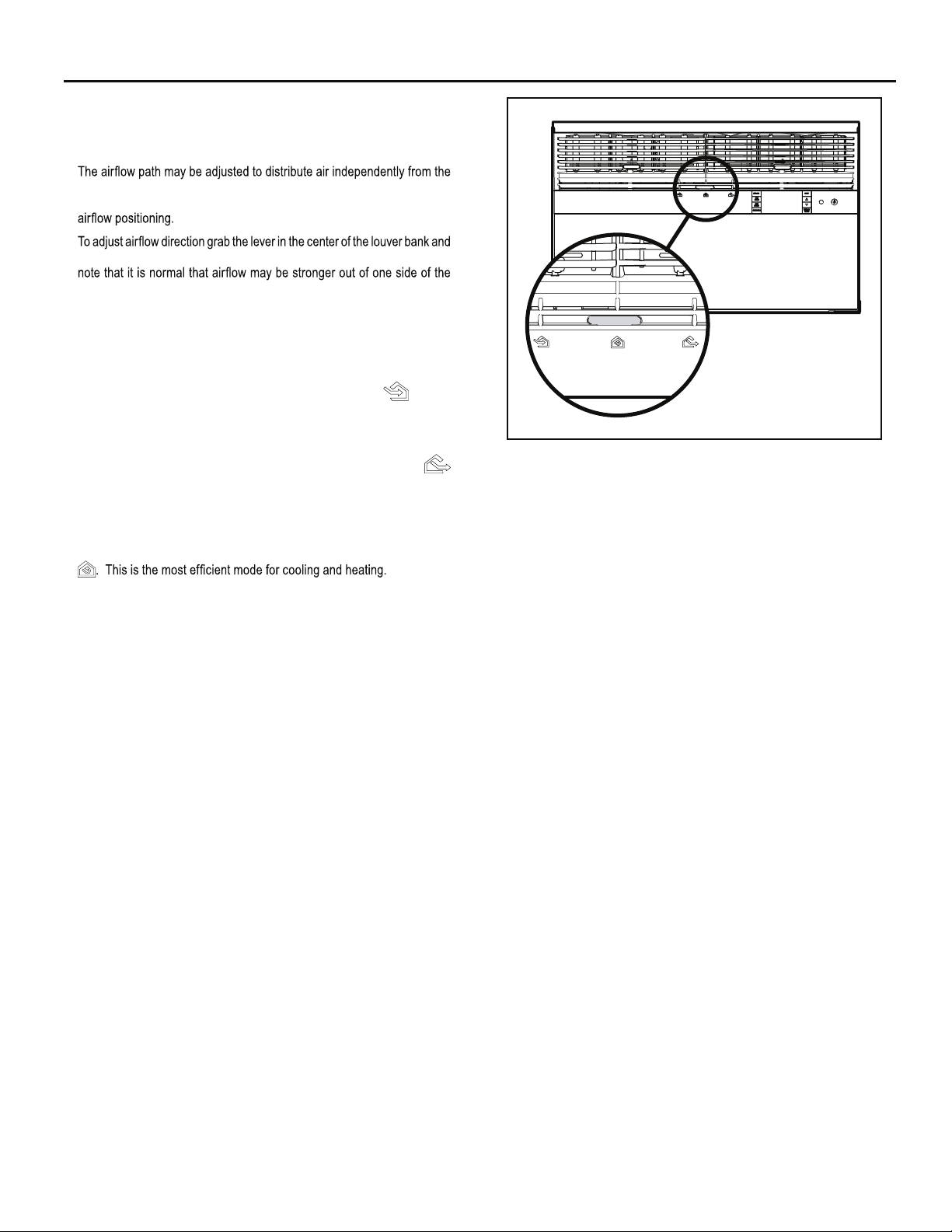
Airflow Selection and Adjustment
Air flow direction adjustment
left or right side of the discharge opening. Each of the banks of louvers
can be directed left, right, up or down in order to achieve the most optimum
move it in the direction that you would like the air to be directed. Please
louvers than the other.
Fresh air and exhaust control
Your air conditioner has the ability to bring fresh air into the room or exhaust
stale air out of the room. The control slide is found on the upper part of
the unit (See Figure 13).
TO BRING IN FRESH AIR – Move the lever to the Fresh Air
which allows outside air to enter the room. This is useful in fall and spring as
a means of bringing in fresh outside air when using FAN ONLY . It can also
be used in the summer with the compressor in the Cooling Mode if you wish.
TO EXHAUST INDOOR AIR – Move the lever to the Exhaust
position. This will allow stale air to be expelled to the outside of the dwelling.
This is especially handy in the spring or fall when indoor air tends to get
stale, or after a social gathering involving smokers, or to remove cooking
odors.
BEST PERFORMANCE – Move the lever to the Re-Circulate Position
position
Figure 13
FRR008
17
Page 18
Installation Instructions
READ THIS FIRST! Electrical Requirements
WARNING
Electrical Shock Hazard
Make sure your electrical receptacle has the
same configuration as your air conditioner’s
plug. If different, consult a Licensed Electrician.
Do not use plug adapters.
Do not use an extension cord.
Do not remove ground prong.
Always plug into a grounded 3 prong oulet.
Failure to follow these instructions can result in
death, fire, or electrical shock.
IMPORTANT: Before you begin the actual installation of your air
Your air conditioner must be connected to a power source with the same
alternating current (A.C.) voltage and amperage as marked on the name
plate located on the chassis. Only A.C. can be used. Direct Current (D.C.)
cannot be used.
CIRCUIT PROTECTION – Use on single outlet circuit only. An overloaded
circuit will invariably cause malfunction or failure of an air conditioner,
therefore, it is necessary that the electrical protection is adequate. Due
to momentary high current demand when the air conditioner starts, use a
"TIME DELAY" fuse or a HACR type circuit breaker. Consult your dealer
or power company if in doubt.
Refer to the electrical name plate located on the air conditioner chassis
(See page 2) to determine the correct fuse or circuit breaker amperage
for your model (See Table 1 on Page 6 for electrical receptacle types).
The power cord has a plug with a grounding prong and a matching
receptacle is required.
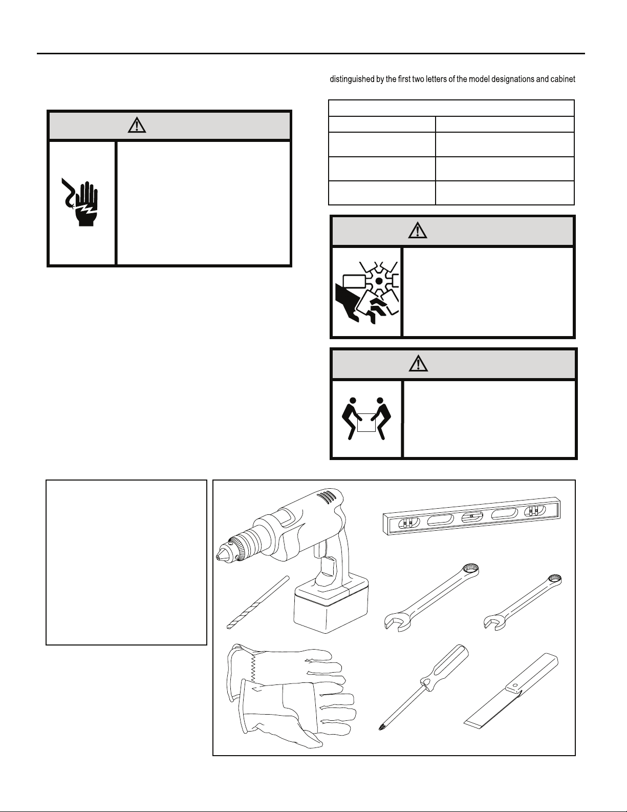
The following instructions are for standard chassis model groups
sizes listed in Table 3.
Table 3
MODEL DESIGNATION CABINET SIZE (H x W x D)
SMALL CHASSIS - SS,
ES, YS
MEDIUM CHASSIS - SM,
EM, YM
LARGE CHASSIS - SL,
EL, YL
15 15⁄16" x 25 15⁄16" x 29" (405 mm x
660 mm x 737 mm)
15
17
⁄16" x 25 15⁄16" x 29" (455 mm x
660 mm x 737 mm)
20 3⁄16" x 28" x 35 1⁄2" (513 mm x 711
mm x 851 mm)
WARNING
MOVING PARTS HAZARDS
* Do not operate unit out of sleeve
or with front grille removed.
.woleb noitamrofni eht dna sedoc lacirtcele lacol kcehc ,renoitidnoc
* Do not place hands in blower or
fan blade areas.
Failure to do so can result in
serious injury.
CAUTION
Excessive Weight Hazard
Use two or more people when
installing your air conditioner.
Failure to do so can result in
back or other injury.
Recommended Tools
1. Power Drill
2. 5/32" Drill Bit
3. Gloves
4. Carpenters Level
5. 5/16" Wrench
6. 1/4" Wrench
7. #2 Phillips Screw Driver
8. Putty Knife or (wood stir stick)
18
4
1
5/16
2
3
ITEMS NOT TO SCALE
5/16
/4
1
1
/4
65
87
Page 19
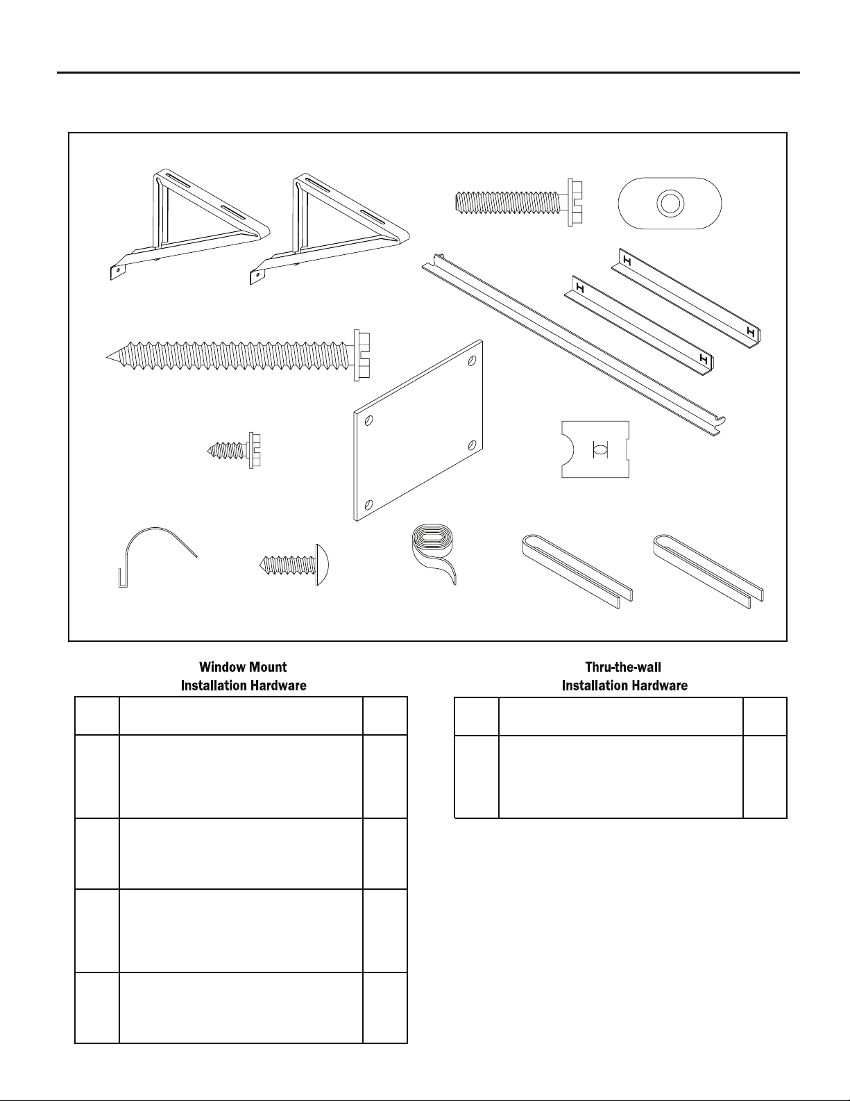
INSTALLATION HARDWARE AND ACCESSORY DETAIL
ITEM 10
ITEMS NOT TO SCALE
ITEM 1
ITEM 4
ITEM 7
ITEM 11
ITEM 12
ITEM 8
ITEM 2
ITEM 5 ITEM 6
ITEM 9
ITEM 13
ITEM 3
ITEM 14
FRR009
ITEM
DESCRIPTION QTY.
NO
WINGBOARD MOUNTING PARTS
8 WINGBOARD (MASONITE) 1
9 "J" TYPE SPEED NUT 4
10 WINGBOARD CLIP (SPRING STEEL) 4
11 SCREW, #8 x ½" PHILLIPS TRUSS HD. 4
WINDOW SEALING
12 SEALING GASKET (VINYL) 1
13 WINDOW SEAL GASKET (DARK FOAM) 1
14 CHASSIS SEAL GASKET (LIGHT FOAM) 1
SHELL MOUNTING PARTS
1 SUPPORT BRACKET 2
2 SCREW, 10-24 x 1" HEX HEAD 4
3 10-24 FLAT WELD NUT 4
4 SCREW, SHEET METAL #12 x 2" 7
WINGBOARD ANGLE MOUNTING
5 WINGBOARD ANGLE, TOP 1
6 WINGBOARD ANGLE, SIDE 2
7 SCREW, SHEET METAL #8 x 3!8" 2
ITEM
DESCRIPTION QTY.
NO
NOTE: Kü h l + models do n ot come with window m ounting
MOUNTING PARTS
4
SCREW, SHEET METAL #12A x 2”
CHASSIS SEAL GASKET (LIGHT FOAM)
14
components. When mounting a cooling and heating model
a window installation kit must be purchased separately.
7
1
KWIKS – For all ES and YS models.
KWIKM – For all EM and YM models.
KWIKL – For all EL and YL models.
19
Page 20
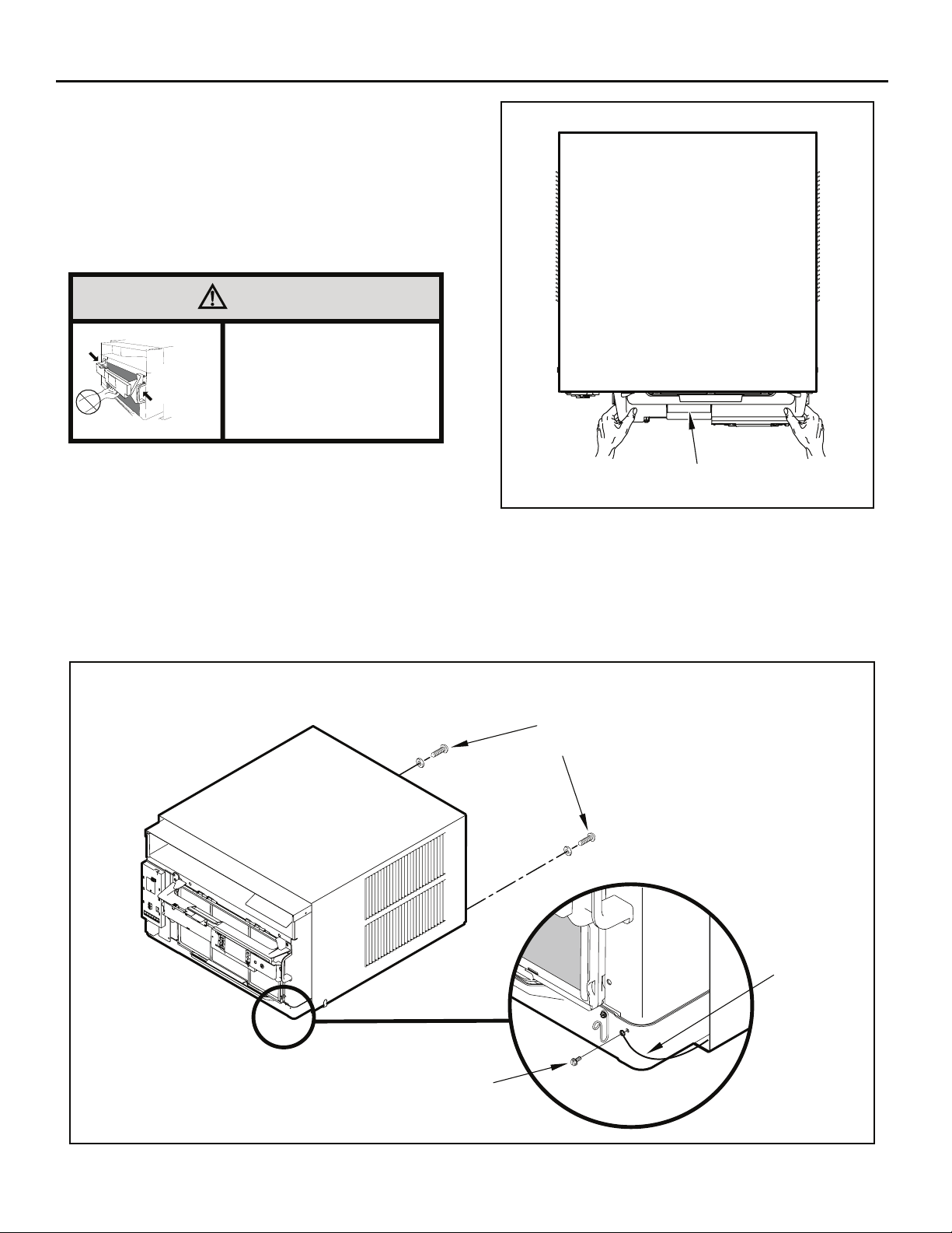
Standard Window Installation
NOTE: Hardware and accessories used during installation are shown
on page 18. Each part will be referred as Item No.
Figure 15
STEP 1. Remove the chassis Entrygard retainer by removing the far
right screw (See Figure 14), save this screw to reattach the
chassis retainer after installation (Step 12). Also, remove and
discard the two retainer screws and washers located at the
rear of the unit (See Figure 14).
CAUTION
Handle Use
Use handle on both sides to
eldnaH esU
pull unit from sleeve.
snoitacoL
]sedis htob[
Do not push, pull or lift from
center of support.
STEP 2. Hold the cabinet stationary, then use the hand grips on both
ends of the control unit support bracket to pull the chassis out
of the cabinet (See Figure 15).
STEP 3. Remove the large white foam blocks used to restrain the
compressor during shipment (See Figure 16). Inspect base
pan for dislodged white foam blocks and remove. Do not
remove any other foam parts.
CONTROL UNIT
SUPPORT BRACKET
STEP 4. Anchor the side angles (Item 6) by engaging the tabs of the
lower sill plate (See Figure 17, Detail B-2) with the loops of the
side angle. Engage the tabs of the top angle (Item 5) with the
top loops of the side angle (See Figure 17, Detail B-1). Install
two (2) screws (Item 7) to secure the top angle tabs and the
side angle to the cabinet (See Figure 17, Detail B-1).
FRR012
Figure 14
RETAINER SCREWS
AND WASHERS
ENTRYGARD
RETAINER
WIRE
FAR RIGHT
SCREW
20
FRR011
Page 21
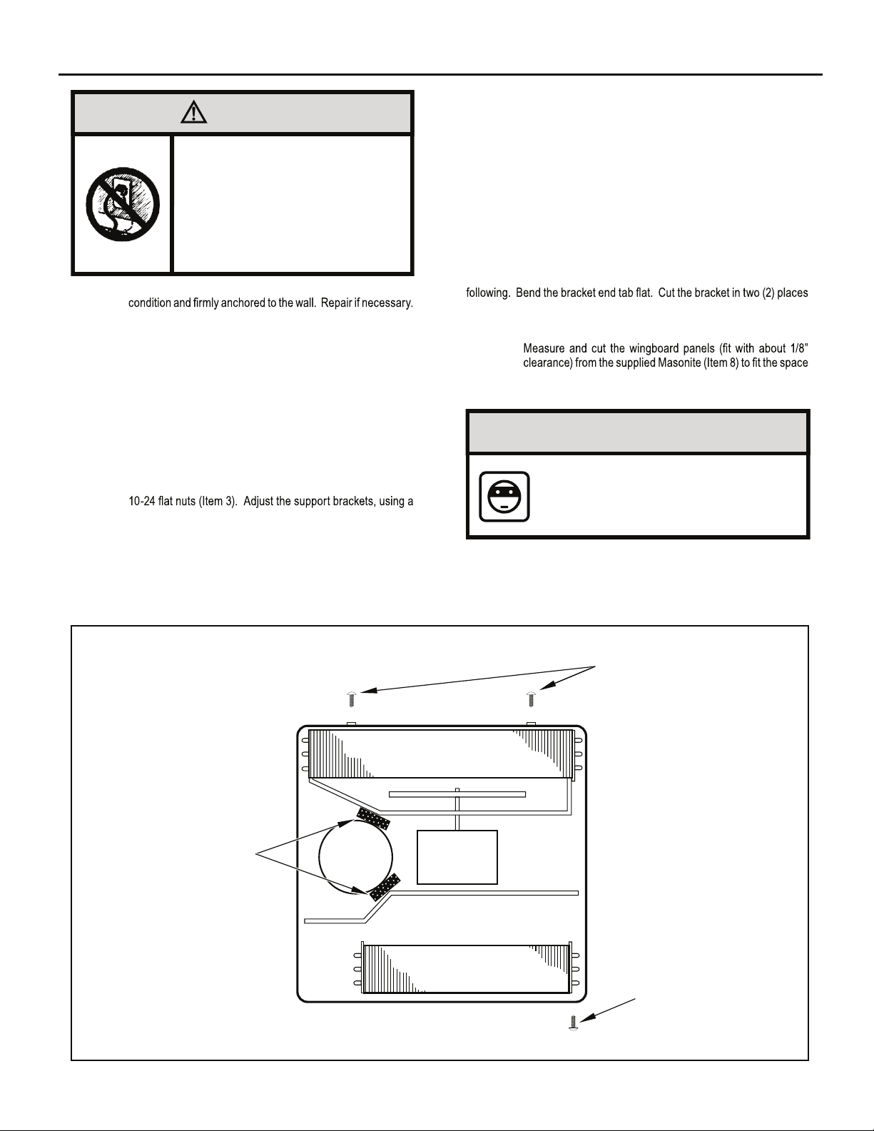
CAUTION
TOP VIEW OF UNIT
Remove Shipping Blocks
Prior to operating the unit remove
the foam shipping blocks.
Failure to do so may result in
damage to the unit which is not
covered by the manufacturer’s
warranty!
STEP 5. Check the window sill and frame to be sure they are in good
STEP 6. CABINET MOUNTING – Raise the lower window 1/4" more
than the height of the cabinet. Carefully slide the cabinet
through the opening until the lower sill plate channel rests
behind the window sill and the top angle rests against the
window (See Figure 18). Center the cabinet within the
opening. Drill three (3) 5/32" diameter pilot holes into window
sill using the holes in the cabinet sill plate as a guide. Install
three (3) #12 x 2" long screws (Item 4) (See Figure 18).
STEP 7. OUTSIDE SUPPORT MOUNTING – Refer to Figures 19 and
20. Assemble the support brackets (Item 1) to the bottom of
the cabinet with four (4) 10-24 1” long screws (Item 2) and four
combination of the elongated holes of the bracket and different
hole locations in the cabinet, to bring the bottom support bracket
pads in contact with the wall. A 1" x 4" or 2" x 4" SPACER
SHOULD BE USED BETWEEN THE WALL AND SUPPORT
THE BRACKETS WHEN INSTALLED ON ALUMINUM OR
VINYL SIDING. Drill 5/32" diameter pilot holes and secure
the brackets to the wall with two (2) 12A x 2" long screws
(Item 4).
Figure 16
NOTE: DO NOT LEVEL the cabinet from front to back. Make sure there
is approximately 3/8” to 1/2” slope (1/8 to 1/4 bubble on level)
toward the outside of the house.
Adjust the support brackets to provide an inside-to-outside slope for excess
condensation drainage (Refer to Standard Window Installation, Figures 19
through 23). Tighten all screws.
Alternate support method A: If you have a wide window sill which prevents
:gniwollof eht yrt ,22 erugiF ni nwohs sa stekcarb eht gnitnuom morf uoy
Using the elongated holes and different hole locations in the cabinet,
.)22 erugiF( thgiew s’tinu eht troppus ot tekcarb eht fo tnemecalp eht tes
Tighten all screws.
Alternate support method B: If the window ledge gap is narrow, try the
as shown in Figure 23. Bend the short piece so it will be vertical when
installed. Adjust the placement as required. Tighten all screws.
STEP 8.
.)42 erugiF( .tenibac dna slennahc edis wodniw eht neewteb
Make sure you include the depth of the window channel.
NOTICE
For YOUR security and safety, YOU must
provide a means of preventing the upper
part of the window from opening.
STEP 9. To assemble the wingboard panels, push on the "J" type speed
nuts (Item 9) and spring steel clips (Item 10) (See Figures 25)
on page 26. Secure each panel with two (2) screws (Item 11).
LEFT SIDE
REMOVE AND DISCARD
FOAM BLOCKS
COMPRESSOR
BACK
FAN MOTOR
EVAPORATOR COIL
FRONT
REMOVE AND DISCARD
SCREWS
RIGHT SIDE
REMOVE AND SAVE
SCREW FOR
RE-INSTALLATION
FRR045
21
Page 22
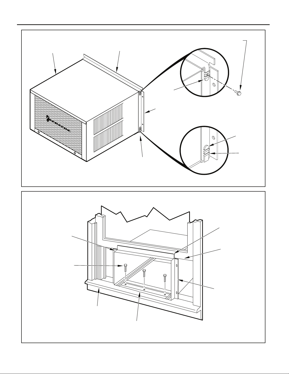
Figure 17
CABINET
#8 x 3/8” LONG SCREW
(ITEM 7) 2 REQUIRED
TOP ANGLE (ITEM 5)
TAB
Figure 18
DRILL (3) 5/32” DIA.
PILOT HOLES AND
INSTALL (3) #12 x 2”
LONG SCREWS
CENTER
CABINET
IN WINDOW
SIDE TO SIDE
(ITEM 4)
SILL PLATE
TAB
SIDE ANGLE
(ITEM 6)
2 REQUIRED
DETAIL B-2
DETAIL B-1
TAB
LOOP
FRR013
TOP ANGLE
(ITEM 5)
PULL WINDOW
SASH DOWN
BEHIND TOP
ANGLE
22
SIDE ANGLE
(ITEM 6)
WINDOW SILL
LOCATE SILL PLATE GUIDE CHANNEL
JUST BACK OF WINDOW SILL
FRR014
Page 23
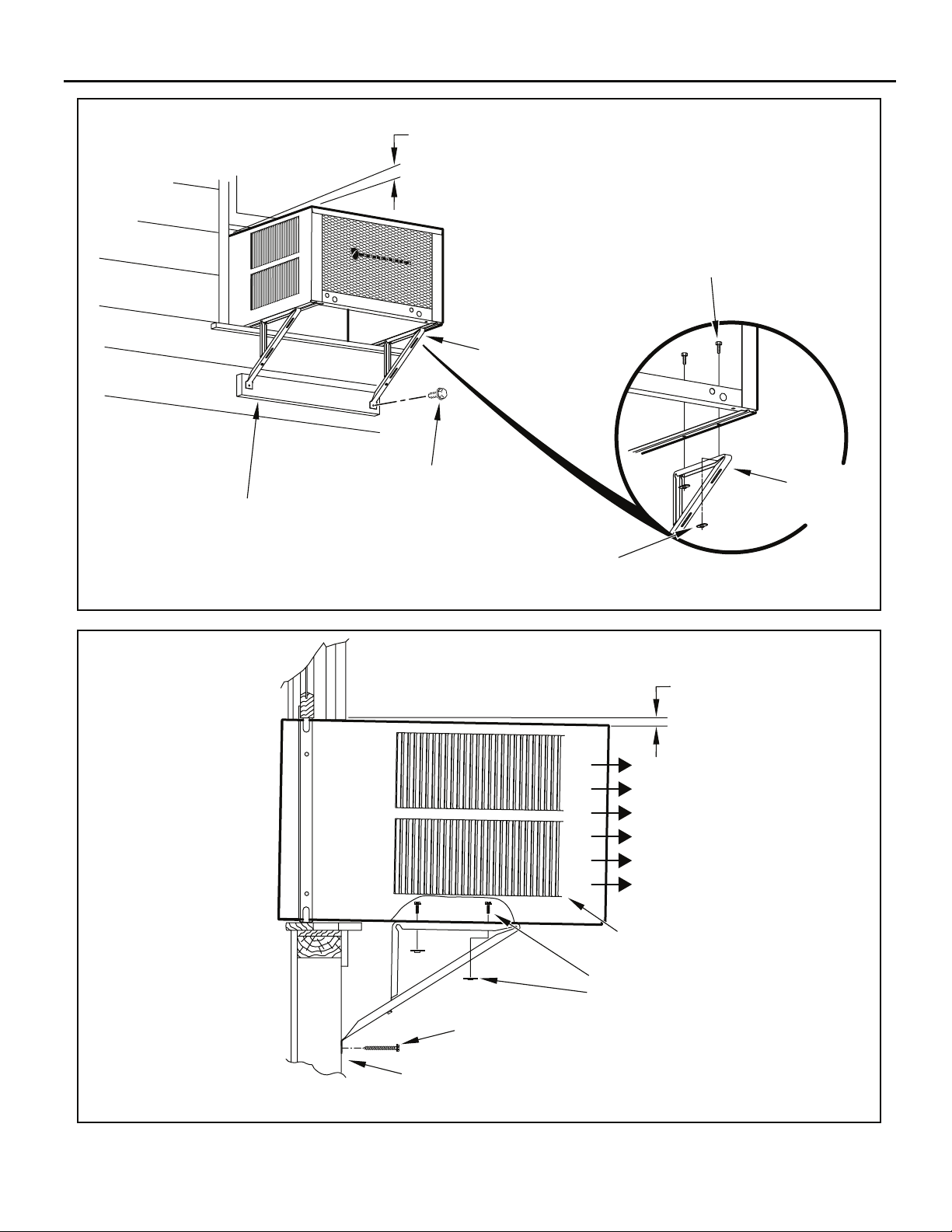
Figure 19
3/8” SLOPE DOWN
#10-24 x 1” HEX HD.
SCREW (ITEM 2)
SUPPORT BRACKET
(ITEM 1)
SPACER SHOULD BE USED BETWEEN
WALL AND BRACKET WHEN INSTALLED
ON ALUMINUM OR VINYL SIDING.
Figure 20
#12 x 2” SCREW
(ITEM 4)
SUPPORT
BRACKET
(ITEM 1)
10-24 x FLAT WELD
NUT (ITEM 3)
FRR015
3/8” SLOPE DOWN
CONDENSER
AIR OUTLET
CONDENSER
AIR INLETS
#10-24 SCREW
#10-24 FLAT WELD NUT
#12 x 2” SHEET METAL
SCREW (ITEM 4)
SPACER SHOULD BE USED BETWEEN
WALL AND BRACKET WHEN INSTALLED
ON ALUMINUM OR VINYL SIDING.
FRR016
23
Page 24
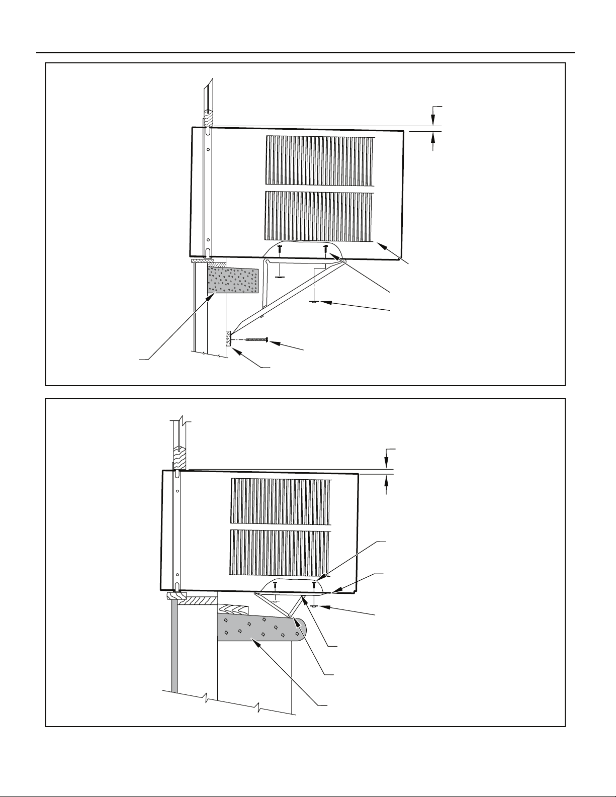
Figure 21
STONE LEDGE
3/8” SLOPE DOWN
CONDENSER
AIR INLETS
#10-24 SCREW
#10-24 FLAT WELD NUT
#12 x 2” SHEET METAL
SCREW (ITEM 4)
SPACER
FRR017
Figure 22
3/8” SLOPE DOWN
#10-24 SCREW
STRAIGHTEN TAB TO LAY FLAT
ALONG THE BOTTOM RAIL OF
THE SHELL
#10-24 FLAT WELD NUT
SECURE THE LONGEST SIDE OF
THE BRACKET TO THE SHELL
ADJUST IN OR OUT TO REST
ON THE LEDGE
24
STONE LEDGE
FRR018
Page 25
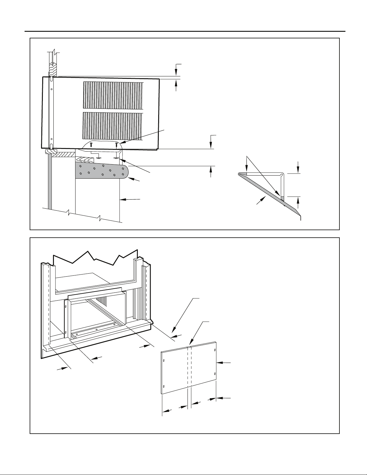
Figure 23
3/8” SLOPE DOWN
Figure 24
#10-24 SCREW
#10-24 FLAT WELD NUT
STONE LEDGE
OUTSIDE WALL
DIMENSION “A”
CUT
HERE
CUT TO FIT DIMENSION “A”
AND BEND DOWN TO FORM
A VERTICAL LEG.
A
DISCARD
SHADED AREA
MEASURE DISTANCE “B” TO INSIDE OF THE
CHANNEL ON EACH SIDE.
FRR019
B
B
B
CUT HERE AND DISCARD CENTER WASTE
MATERIAL.
WINGBOARD
B
SUBTRACT 1/8” FROM DIMENSION “B” AND
MEASURE FROM THE EDGE OF THE WINGBOARD (ITEM 8), MARK, SCORE AND CUT
WITH APPROPRIATE CUTTING TOOL.
FRR020
25
Page 26
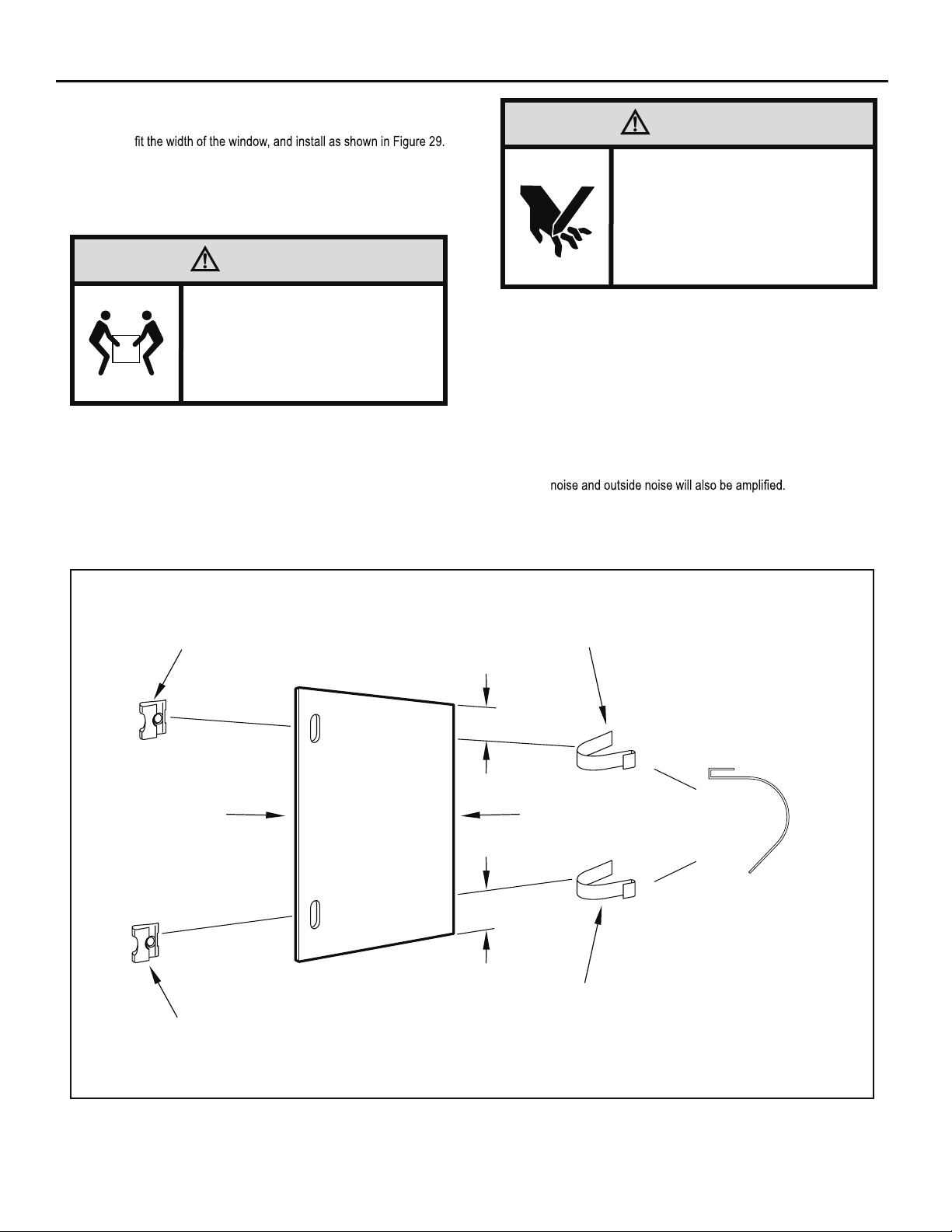
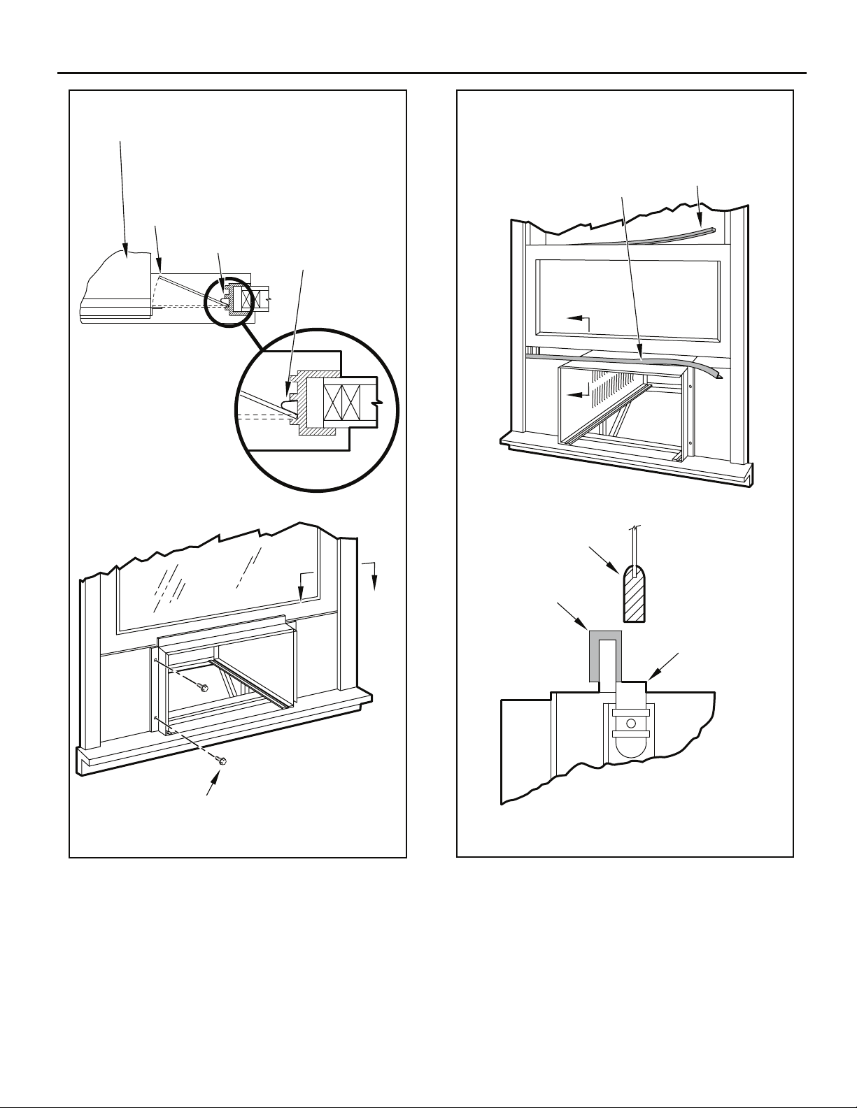
STEP 10. INSTALL THE WINDOW SEALING GASKETS – Measure
and cut the vinyl window seal gasket (grey color, Item 12) to
CAUTION
Figure 25
Pull the window sash down behind the gasket. Measure and
cut the dark foam window seal gasket (Item 13) and install it
between the upper glass panel and the top part of the lower
window sash (Figure 29).
CAUTION
Excessive Weight Hazard
Use two or more people when
installing your air conditioner.
Failure to do so can result in
back or other injury.
“J” TYPE SPEED NUT
(ITEM #9) 2 REQUIRED
Cut/Sever
Although great care has been
taken to minimize sharp edges
in the construction of your unit,
use gloves or other hand
protection when handling unit
Failure to do so can result in minor
to moderate personal injury.
STEP 11. Carefully team lift the chassis and set it into the cabinet. Slide
the chassis stopping approximately 3" from full insertion. Insert
the chassis seal gasket (Item 14) one inch deep between the
.82 egap no nwohs sa )92 erugiF eeS( tenibac eht dna sissahc
A paint stir stick or ruler might be helpful here. Begin inserting
the gasket at either bottom corner and go up the side, across
the top, and down the opposite side. Then push the chassis
all the way into the cabinet.
NOTE: If the chassis seal gasket is not installed or installed improperly,
the operation of the unit will be negatively affected. Operational
STEP 12. Reattach the entry guard chassis entry guard retainer wire with
the same screw retained in Step 1 (See Figure 14).
SPRING STEEL
CLIP (ITEM 10)
2 REQUIRED
26
CUT
WINGBOARD
PANEL
CENTER THE HOLE IN THE
SPEED NUT OVER THE SLOT
IN THE WINGBOARD PANEL
3"
CUT EDGE
3"
SLIDE CLIP OVER CUT EDGE
OF WINGBOARD PANEL
ROTATED 90°
FRR021
Page 27
FRR023
TOP OF CABINET
Figure 27Figure 26
PLACE WINGBOARD PANEL IN WINDOW JAM
TO COMPRESS THE SPRINGS INSIDE THE
RUNNERS, AND SWING THE WINGBOARD
PANELS INTO PLACE AS INDICATED BY THE
DASHED LINES.
WINDOW JAM
CLIP (ITEM 10)
SECTION A-A
INSERT VINYL WINDOW SEAL
GASKET OVER TOP ANGLE
TO WINGBOARD (ITEM 12)
B
B
LOWER WINDOW SASH
INSERT FOAM WINDOW
SEAL GASKET (ITEM 13)
A
SECURE THE SIDE WINGBOARD PANELS TO
THE SIDE ANGLES WITH FOUR (4) #8 x 1/2” LONG
SCREWS (ITEM 11), TWO ON EACH SIDE.
A
FRR022
VINYL
WINDOW
GASKET
TOP WINGBOARD ANGLE
SECTION B-B
27
Page 28
OPTIONAL: The factory assembles the supply cord so that it exits the left
side of the unit at the bottom. At the consumer’s discretion,
To do this, route the supply cord to the right side. Pull the
supply cord taunt through the loops (Refer to Cord Routing
Change, Figure 30) and route the cord down.
Use Tool Provided
.tinu eht fo edis thgir eht tixe ot detuor eb nac droc ylppus eht
Please use the provided tool to attach the decorative front to the chassis.
Figure 28
STEP 13.
To attach and prevent damage to the front grille align the
cord notch over the cord and center the fresh air lever, then
align and tighten the four (4) captive screws as indicated by
the arrows in Figure 28. Before closing the front panel, be
sure the filter is in place. Make sure curtains do not block
the side air intakes.
STEP 14. Refer to the Control Panel Operation section for instructions.
STEP 15. You are now ready to control the comfort level of the room.
Figure 29
USE HAND TOOLS
DO NOT O VER T IGHTE N
B
LOCATION OF GRILLE
REMOVAL TOOL
FRR053
28
POWER CORD
CLIP
NOTE: WHEN INSTALLING THE CHASSIS
SEAL GASKET; BEGIN AT EITHER BOTTOM
CORNER AND GO UP THE SIDE & ACROSS
THE TOP & DOWN THE OPPOSITE SIDE.
CHASSIS SEAL
GASKET (ITEM 14)
FRR024
Page 29

THIS PAGE INTENTIONALLY LEFT BLANK
29
Page 30
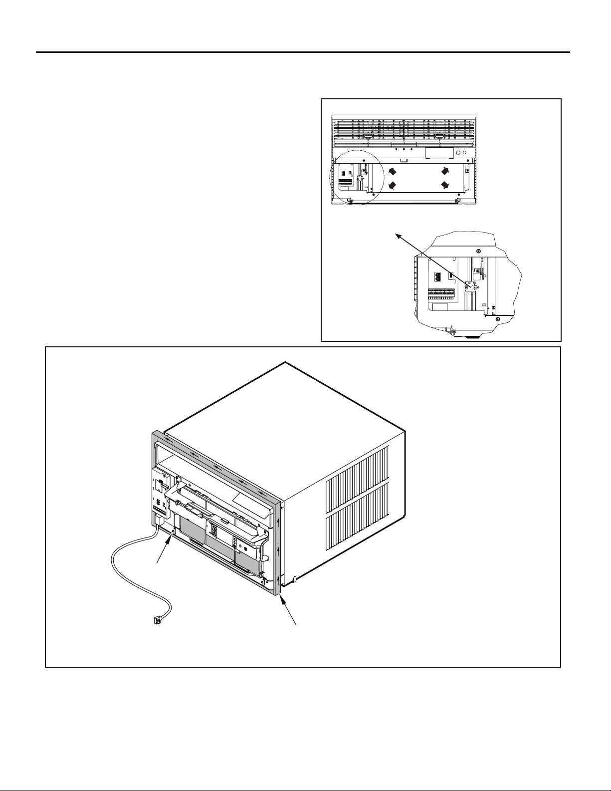
Cord Routing Change
FRR054
Unplug unit.
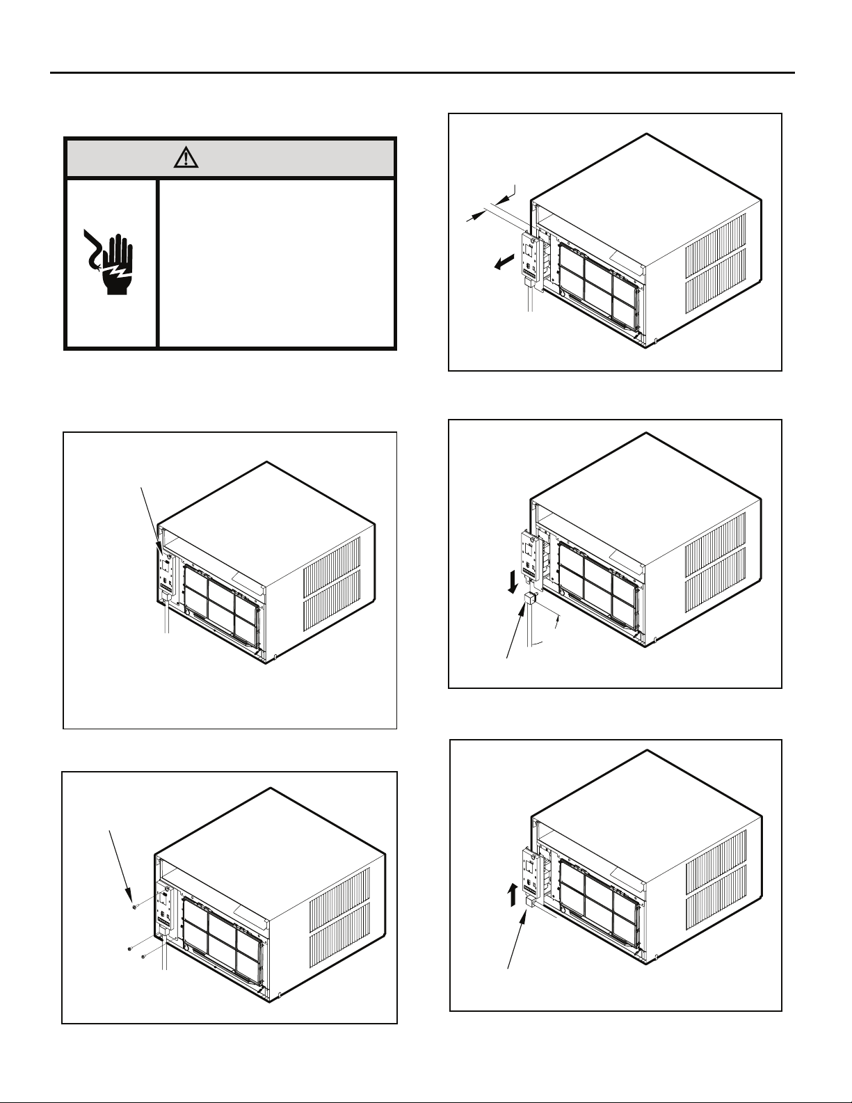
STEP 16. Carefully pull out electrical control panel 1", but not all the way.
Figure 32
WARNING
Electrical Shock Hazard
Make sure your electrical receptacle has the
same configuration as your air conditioner’s
plug. If different, consult a Licensed Electrician.
Do not use plug adapters.
Do not use an extension cord.
Do not remove ground prong.
Always plug into a grounded 3 prong oulet.
Failure to follow these instructions can result in
death, fire, or electrical shock.
For convenience and optimum appearance the direction that the power cord
exits the unit may be changed from left to right by following the procedure
below. Select the exit location on the left or right based on proximity to
the power outlet.
Figure 30
ELECTRICAL
CONTROL PANEL
1 INCH
FRR056
STEP 17. Pull electrical cord strain relief downward until free and rotate
90 degrees to the right.
Figure 33
NOTE:
DECORATIVE FRONT REMOVED USE TOOL PROVIDED.
(SEE FIGURE 28 FOR LOCATION OF TOOL).
Remove 3 screws as shown from the electrical control panel. Save to
reinstall later.
Figure 31
ELECTRICAL CONTROL
PANEL SCREWS (3)
FRR055
90°
ELECTRICAL CORD
STRAIN RELIEF
FRR057
STEP 18. Push electrical cord strain relief back upward into the electrical
control panel.
Figure 34
ENSURE THE ELECTRICAL CORD STRAIN RELIEF IS
FLUSH WITH THE TOP OF ELECTRICAL CONTROL PANEL
FRR058
30
Page 31

STEP 19. Carefully push electrical control panel back into chassis.
Figure 35
ELECTRICAL
CONTROL PANEL
FRR059
STEP 20. Reinstall the 3 screws removed earlier to secure electrical
control panel.
Figure 36
STEP 21. If running power cord to the right of the unit install the cord
into the cord retainer clips along the bottom front of the unit.
Figure 37
CORD RETAINER
CLIPS
POWER
CORD
ELECTRICAL CONTROL PANEL SCREWS (3)
(RETAINED FROM STEP 1)
FRR060
FRONT
GRILLE
FRR061
31
Page 32

Through-the-Wall Installation
The following instructions apply to wood, masonry, brick, concrete or cinder
block wall construction.
STEP 1. Follow steps 1, 2, 3, and 4 of the "STANDARD WINDOW
INSTALLATION" instructions beginning on page 20.
STEP 2. CABINET PREPARATION – Remove the sill plate from the
Note that the chassis retainer is secured by a right side nut
and screw (Detail A, Figure 38). Bend the tabs of the sill plate
down into its channel at both ends of the plate or cut them off
(Detail B, Figure 38) Rotate the sill plate 180° (end-to-end,
Detail B, Figure 38) and reinstall. Reverse the orientation of
the nuts and screws, so that the head of the screws are on the
underside of cabinet facing up and the nuts are on top (Detail
C, Figure 38). Ensure that the chassis retainer is reinstalled
as shown in the detail.
NOTICE
The outside cabinet condenser air intake louvers
MUST NOT BE BLOCKED by extra thick walls.
STEP 3. WALL PREPARATION – The maximum wall thickness
permissible without special construction is determined by
the model size to be installed. Observe the maximum wall
thickness shown in Figure 39. Walls exceeding the maximum
thickness shown in the chart, should be altered as shown in
Figure 39.
STEP 4. CHECKING WIRING AND PLUMBING – Check for wiring and
plumbing inside and outside of the wall to be sure none will be
damaged when the cabinet framework is being constructed.
.)83 erugiF( swercs dna stun )4( owt gnivomer yb tenibac
A
B
Table 4
FINISHED
DIMENSION
A 16 3⁄16" 18 3⁄16" 20 3⁄8"
B 26 3⁄16" 26 3⁄16" 28 1⁄4"
SMALL
CHASSIS
MEDIUM
CHASSIS
LARGE
CHASSIS
size.
STEP 5. OPENING CONSTRUCTION – Depending upon size of unit
to be installed, lay out the hole dimensions per Table 4. Cut
construction is typical frame or 2” x 4” studding with brick or
For masonry, concrete or cinder block walls, locate opening
for your convenience (See Figures 40, 41, and 42).
32
.sduts eht fo eno ot txen gninepo eht etacol ,sreenev enots
Page 33

Figure 38
CABINET
BEFORE AFTER
SCREW
(4 REQUIRED)
CABINET
SILL PLATE
TURN SILL PLATE
END TO END
Figure 39
A
MAXIMUM WALL THICKNESS
CONDENSER AIR
INTAKE LOUVERS
NOTE: HOLES IN SILL
PLATE MOVED TO
BACK SIDE
DETAIL A
NUT
(4 REQUIRED)
DETAIL B
BEND TABS DOWN
NOTE: SCREW AND NUT
ORIENTATION NOW REVERSED.
TOP VIEW
NUT
(4 REQUIRED)
DETAIL C
SCREW
(4 REQUIRED)
FRR026
CONDITIONED
ROOM SIDE AIR
MODEL A
SMALL CHASSIS 7-3/8”
MEDIUM CHASSIS 7-3/8”
LARGE CHASSIS 15-1/8”
TOP VIEW SHOWING
BEVELED SIDES FOR
AIR INTAKE.
WALL BELOW UNIT MUST
BE BEVELED ALSO.
NOTE: CONDENSER AIR INLETS AND OUTLETS
MUST BE UNOBSTRUCTED TO AVOID THE
RECIRCULATION OF REJECTED HEATED AIR.
2" MINIMUM
BOTH SIDES
CONDENSER AIR
INTAKE LOUVERS
CONDENSER AIR
OUTLET / REJECTED
HEATED AIR
FRR027
33
Page 34

Figure 40
Figure 41
CAULK ALL SIDES
INSIDE AND OUTSIDE
CABINET
SHIM TO FILL IN VOID AT THE
TOP AND SIDES WITH WOOD
AS REQUIRED.
ELECTRICAL RECEPTACLE
(SEE FIG. 42 FOR LOCATION NOTE)
FRR028
CAULK ALL SIDES
INSIDE AND OUTSIDE
CABINET
SHIM TO FILL IN VOID AT THE
TOP AND SIDES WITH WOOD
AS REQUIRED.
ELECTRICAL RECEPTACLE
(SEE FIG. 42 FOR LOCATION NOTE)
FRR029
Figure 42
MORTAR
CABINET
CAULK ALL SIDES
INSIDE AND OUTSIDE
POINT “X”
POINT “Y”
From Point "X" Small/Medium Large
115V 69” N/A
230V 45” 45”
From Point "Y" Small/Medium Large
115V 45” N/A
230V 21” 20”
ELECTRICAL
RECEPTACLE
FRR030
34
Page 35

STEP 6. Slide the cabinet into the hole far enough to allow the
guide-channel of the sill plate to contact the inside wall surface
(Figure 20).
STEP 7. Drill three (3) 5/32” diameter pilot holes (use the sill-plate holes
as a guide) into the frame and install three (3) #12 x 2" long
screws (Item 4) (Figure 20).
NOTE: Alternate fasteners are required when securing the sill plate or
support brackets to material other than wood (cinder block, brick,
masonry or concrete). These items can be purchased at your
local hardware store.
EXPANSION ANCHOR BOLT
MOLLY OR TOGGLE BOLT
Figure 43
NOTE: DO NOT LEVEL the cabinet from front to back. Make sure there
is approximately 3/8” to 1/2” slope (1/8 to 1/4 bubble on the level)
toward the outside of the house.
STEP 8. Drill two (2) 5/32" diameter pilot holes in each cabinet side
at the locations shown (Figure 20) and install four (4) #12 x
2" screws (Item 4). Provided that Step 5 (hole construction)
provides a sturdy mount with solid vertical studs, support
brackets may not be required. The installation must support
the weight of the unit plus an additional weight of 400 pounds
on the rear of the cabinet. If support brackets (Item 1) are
available, they can be installed as shown in Figure 20.
STEP 9. Complete the installation by following steps 12 through 15
of “STANDARD WINDOW INSTALLATION” instructions,
page 20.
TRIM MOULDING
4"
SCREW #12 x 2"
LONG (USE 3)
(ITEM 4)
SILL PLATE GUIDE CHANNEL
INSIDE WALL SURFACE
CAULK ALL SIDES WEATHER TIGHT
INSIDE AND OUTSIDE
3/8" SLOPE DOWN
3"
NOTE: SUPPORT BRACKET MAY BE
OMITTED FROM THROUGH-THE-WALL
INSTALLATIONS IF THE CABINET IS
SECURED AS FOLLOWS. DRILL TWO
HOLES IN EACH SIDE AND INSTALL 4
FASTENERS (2 EACH SIDE). USE #12 x 2"
SCREWS, (ITEM 4).
TOGGLE BOLTS OR EXPANSION BOLTS
MAY BE REQUIRED.
CABINET
SUPPORT BRACKETS
SCREW #12 x 2" LONG
DRILL 5/32" DIA. PILOT HOLES.
FRR031
35
Page 36

Programmable Thermostat
Your unit’s digital control features an advanced 7 day programmable
thermostat feature that can be used to turn the unit on or off or even
change modes and maintain temperatures throughout the day.
Factory settings are shown in addendum 1 (Schedule Table with Energy
Saving Values). These values can be changed by following the procedures
in the preceding paragraphs. Basic options are: Four (4) day groups.
1. Monday through Friday.
2. Saturday and Sunday only.
3. Monday through Sunday.
4. Individual days (Mon thru Sun).
Each of the day groups have four (4) time periods: WAKE (06:00), AWAY
(08:00), RETURN (18:00), and NIGHT (22:00).
The start time for each of the time periods can be changed. In addition,
each time period can have its own temperature and fan mode.
For example, let’s say you are in a cool climate region. You leave for work
at 08:00 and return home around 18:30. You can set the temperature lower
while you are away from your home. At 18:00, you set the temperature
higher for the RETURN period so the room is nice and comfortable when
you arrive.
Set Schedule Sequence – 1 Wake Period
SYSTEM
FAN
MODE
FAN
SPEED
SCHEDULE
Press and hold
AUTO
AUTO
<- COOLSET POINT
for three (3) seconds to enter the schedule setting
mode and returns to normal display without saving any settings that might
have been changed. To exit and save the changes, press and hold
for three (3) seconds. All changed parameters will be saved. The
key allows the user to back up through the menus.
SYSTEM
FAN
MODE
FAN
SPEED
M
T F S
S
SCHEDULE
T W
WAKE
the schedule icon blinks. The display begins with all weekday (MTWTF)
dots lit. Changes made will apply equally to all weekdays.
BACK
F
DISPLAY
ENTER
FRR032
BACK
A
M
DISPLAY
ENTER
FRR033
SYSTEM
FAN
MODE
FAN
SPEED
SCHEDULE
M
T F S
T W
S
WAKE
BACK
A
M
DISPLAY
ENTER
FRR034
The user can select a different day group by pressing . If the user
continues to press , the system will cycle through all the day groups
in the following order: MTWTF SS Mon, Tues, Wed, Thur, , Fri,
Sat, Sun.
Note the last day group is each individual day. In other words, the user can
adjust each of the four (4) time period start times per day. This is a real
helpful feature if you have an adjustable work shift. Each day group begins
showing the start time for the wake time period.
SYSTEM
FAN
MODE
FAN
SPEED
SCHEDULE
M
T F S
T W
S
WAKE
BACK
A
M
DISPLAY
ENTER
FRR035
To change the time, press (UP) or (DOWN) to increment/decrement
the time by 15 minute jumps. Once the correct time is set, press to
advance to the next step.
Set Schedule Sequence – 2 Wake Period
SYSTEM
FAN
MODE
FAN
SPEED
SCHEDULE
CONTINUOUS
M
T W
T F S
S
WAKE
Now you can adjust the settings for SYSTEM, FAN MODE, FAN SPEED
and TEMPERATURE.
SYSTEM
FAN
MODE
FAN
SPEED
SCHEDULE
CONTINUOUS
M
T W
T F S
S
WAKE
<- COOLSET POINT
Press , , or to change the perspective option. Use the
(UP) or (DOWN) to adjust the cool setpoint.
BACK
F
DISPLAY
ENTER
FRR036
BACK
F
DISPLAY
ENTER
FRR037
36
Page 37

FRR038
If the system mode is set to AUTO (Heat-Cool Unit only), a 2nd temperature
labeled “Heat !! Set Point” displays. Use (UP) or (DOWN) arrows
to increment/decrement the heat temperature. The other parameters
The temperature range for AUTO mode must remain a minimum of 3
degrees apart at all times. If the high or low temperature is adjusted too
close to its counterpart, that temperature not being directly changed will
increase/decrease as needed to maintain the 3 degree spread. The user
presses
to advance to the next time period.
FRR039
If the user selects FAN-Only mode, the word FAN displays for 2 seconds.
In this mode you may adjust the FAN SPEED. The FAN SPEED options
are: LOW, MED, HIGH or MAX*. Fan speed depends on your unit's
model. The MAX* Setting is available on all SS and SM models.
Set Schedule – Away, Return, Night Periods
Each of the additional periods (Away, Return, Night) are programmed
.neercs siht no degnahc eb tonnac )EDOM NAF ,DEEPS NAF ,METSYS(
identical to the programming for the Wake period. The appropriate
sequence.
Once the user has programmed all four (4) time periods, the program goes
to the next day or day group by pressing SCHEDULE. For example, if
individual days are being programmed, the program will go from Mon to
Tues leading the user through 4 periods for Tues until it reaches the end of
the week.
NOTE: Day group sequence is as follows: Monday through Friday
(weekday), Saturday – Sunday (weekend), Monday through
Sunday (7-day), and individual days Mon !!Tue !!Wed !!Thru
!! !! !!
Note that by pressing SCHEDULE repeatedly the process follows a
continuous loop until the user decides to exit.
When the user has completed setting start times and options (or at any
point in the process) they can press to toggle to the next day (or set of
days), or they can press and hold for 3 seconds to save their changes
and exit the set schedule mode. Once programmed you can SAVE and
EXIT or select another day group by pressing SCHEDULE.
FRR042
FRR040
If the user wants the air conditioner to power down for a period of time,
pressing
hibernation until the next scheduled period. This feature is available during
FRR041
If the user should decide they don’t want to use any or all four time
periods for the day, they can set any period to be pressing This will
blank out the options and display the word SKIP. This can be undone by
pressing again. The digital control defaults to the time period setting
inmediately prior to the user advancing to SKIP. to
continue on to the next time period. SKIP
previous time period, it will terminate at the
Press
,
continue
continues the settings of the
start of the next time period
P is not selected.where SKI
Schedule Mode Completed.
FRR043
37
Page 38

Final Inspection & Start-up Checklist
u Inspect and ensure that all components and accessories have been
installed properly and that they have not been damaged during the
installation progress.
u Check the condensate water drain(s) to ensure that they are adequate
for the removal of condensate water, and that they meet the approval
of the end user.
u Ensure that all installation instructions concerning clearances around
indoor coil, and outdoor coil are free from any obstructions.
u Ensure that the circuit breaker(s) or fuse(s) and supply circuit wire
size have been sized correctly. If the unit was supplied with a power
supply cord, insure that it is stored properly.
u Ensure that the entire installation is in compliance with all applicable
national and local codes and ordinances having jurisdiction.
u Secure components and accessories, such as a decorative front
cover.
u Start the unit and check for proper operation of all components in
each mode of operation.
u Instruct the owner or operator of the units operation, and the
manufacturer's Routine Maintenance.
NOTE: A log for recording the dates of maintenance and/or service is
recommended.
u Present the owner or operator of the equipment with the Installation
& Operation Manual, all accessory installation instructions, and the
name, address and telephone number of the Authorized Friedrich
Warranty Service Company in the area for future reference if
necessary.
Heat pumps operate differently
If your unit is a "Y", or heat pump model, there are some things that you
will want to be aware of. Some functions of a heat pump differ from your
unit when it is used for heating:
1. .pmup taeh eht fo lioc roodtuo eht no mrof ot eci rof lamron si tI
Moisture in the outside air, passing over the coil when very cold,
will form ice.
2. If the outdoor temperature drops below 37° F (3° C), your heat
pump will automatically turn on the electric resistance heat. When
the temperature rises to 40° F (4° C), the compressor will resume
the heat pump operation. If your unit is a 115 volt model (YS10),
it is designed for use in warmer climates and does not have an
electrical heat feature, and will not provide adequate heat below
37° F (2.8° C).
Control Panel Battery Change Procedure
Remove the grille, by loosening four (4) captive screws (See Figure 44). In
the upper left corner, remove one (1) screw on the battery retaining door
(See Figure 45). Remove and replace the battery (CR2450). Reinstall
the battery retaining door. Align the grille guide pins then tighten the four
Clean or replace it as necessary.
Figure 44
This is a warm weather appliance
Your air conditioner is designed to cool in warm weather when the outside
temperature is above 60° F (15.6° C) and below 115° F (46.1° C), so it won't
cool a room if it is already cool outside. If you want to cool a room in the
spring or fall, select the FAN ONLY
air control to Fresh Air. This will bring in a supply of cooler outside air.
mode and set the Fresh Air/Exhaust
Condensation is normal
Air conditioners actually pump the heat and humidity from your room to the
outside. Humidity becomes water, and your air conditioner will use most
of the water to keep the outside coil cool. If there is excessive humidity,
there may be excess water that will drip outside. This is normal operation.
Frosting
ONLY and the frost will disappear. Setting the thermostat a little warmer
will probably prevent the frosting from recurring.
Noises
All air conditioners make some noise. Friedrich units are designed to
operate as quietly as possible. An air conditioner mounted in a wall is
quieter than one mounted in a window. It is important to ensure that the
chassis seal gasket (Item 14) is properly installed (refer to installation
instructions).
USE HAND TOOLS
DO NOT OVER TIGHTEN
1. USE HAND TOOLS WHEN INSTALLING AND
REMOVING FRONT PANEL.
DO NOT OVERTIGHTEN SCREWS.
2. DISCONNECT POWER AND FOLLOW ALL
LABELED WARNINGS WHEN FRONT PANEL
IS REMOVED.
Figure 45
FRR010
38
Page 39

Routine Maintenance
monthly, and more frequently if conditions warrant. The unit must be turned
WARNING
Wall Sleeve
Inspect the inside of the wall sleeve and drain system periodically (annually
or semi-annually) and clean as required. Under extreme conditions, more
frequent cleaning may be necessary. Clean both of these areas with an
antibacterial and antifungal cleaner. Rinse both items thoroughly with
water and ensure that the drain outlets are operating correctly. Check the
sealant around the sleeve and reseal areas as needed.
Electrical Shock Hazard
Make sure your electrical receptacle has the
same configuration as your air conditioner’s
plug. If different, consult a Licensed Electrician.
Do not use plug adapters.
Do not use an extension cord.
Do not remove ground prong.
Always plug into a grounded 3 prong oulet.
Failure to follow these instructions can result in
death, fire, or electrical shock.
To Remove, Wash and Replace Filter
Coils & Chassis
NOTE: .nap esab ro slioc no tnega gninaelc lioc citsuac a esu ton oD
Use a biodegradable cleaning agent and degreaser. The use
of harsh cleaning materials may lead to deterioration of the
The indoor coil and outdoor coils and base pan should be inspected
periodically (annually or semi-annually) and cleaned of all debris (lint, dirt,
leaves, paper, etc.) as necessary. Under extreme conditions, more frequent
cleaning may be required. Clean the coils and base pan with a soft brush
and compressed air or vacuum. A pressure washer may also be used,
pack when pressure cleaning coils.
NOTE: It is extremely important to insure that none of the electrical
and/or electronic parts of the unit get wet. Be sure to cover all
electrical components to protect them from water or spray.
Decorative Front
Use a damp (not wet) cloth when cleaning the control area to prevent
water from entering the unit, and possibly damaging the electronic control.
The decorative front and the cabinet can be cleaned with warm water
and a mild liquid detergent. Do NOT use solvents or hydrocarbon based
cleaners such as acetone, naphtha, gasoline, benzene, etc.
The indoor coil can be vacuumed with a dusting attachment if it appears
to be dirty. DO NOT BEND FINS. The outdoor coil can be gently
sprayed with a hose if you can get to it. If not, you might call your dealer
for a more thorough cleaning when needed.
vacuuming with a dust attachment or by cleaning in the sink using warm
reinstalling. Use caution the coil surface can be sharp.
Fan Motor & Compressor
The fan motor & compressor are permanently lubricated, and require no
additional lubrication.
Service and Assistance
Before calling for service, please check the “Troubleshooting Tips” section
avoid unnecessary service calls, and save you the cost of a service call
if the problem is not due to the product itself. If you have checked the
“Basic Troubleshooting” section and still need help, it is available as follows:
our web site at www.friedrich.com.
If you require further assistance
You can call the Customer Support Call Center at 1-800-541-6645.
Before calling, please make sure that you have the complete model and
serial number, and date of purchase of your equipment available. By
providing us with this information, we will be better able to assist you.
Our specialists are able to assist you with:
u
u Referrals to dealers, and distributors.
u Use and Care Information.
u Recommended maintenance procedures.
u Installation information.
u Referrals to Authorized Service Providers and Parts depots.
Available Accessories
DC-2 Drain Kit – Part No. 01900235
In some installations, excess condensate water caused by extremely humid
conditions, may result in an undesirable water drip such as on a patio or
over an entryway. MODEL DC-2 DRAIN KIT (Part No. 01900-235) can be
installed to drain excess condensation to an alternate location.
Carbon Filter Kits
The kits vary depending on the chassis size (small, medium, large). Each
WCFS
WCFM
WCFL
Remote Wall Thermostats
RT4 – Digital wall thermostat hard wired with single speed fan.
RT5 – Digital wall thermostat hard wired with two fan speed selection,
battery backup and backlight display.
Window Installation Kits (Standard in Kühl
Models without Heat)
KWIKS – For all ES and YS models.
KWIKM – For all EM and YM models.
KWIKL – For all EL and YL models.
See www.friedrich.com for additional accessories for your unit.
39
Page 40

Troubleshooting Tips
COMPLAINT CAUSE SOLUTION
Unit does not operate.
Unit Trips Circuit Breaker or
Blows Fuses.
LCDI Power Cord Trips (Reset
Button Pops Out).
NOTE: A damaged power supply cord must be replaced with a new power supply cord
Unit Does Not Cool/Heat
Room Sufficiently, Or Cycles
On And Off Too Frequently.
● The unit is turned to the off position,
or the thermostat is satisfied.
● The LCDI power cord is unplugged. ● Plug into a properly grounded 3 prong
● The LCDI power cord has tripped
(Reset button has popped out).
● The circuit breaker has tripped or
the supply circuit fuse has blown.
● There has been a local power
failure.
● Other appliances are being used on
the same circuit.
● An extension cord is being used. ● Do NOT use an extension cord with this or any
● The circuit breaker or time-delay
fuse is not of the proper rating.
● The LCDI power cord can trip
(Reset button pops out) due to
disturbances on your power supply
line.
● Electrical overload, overheating, or
cord pinching can trip (Reset button
pops out) the LCDI power cord.
obtained from the product manufacturer and must not be repaired.
● The return/discharge air grille is
blocked.
● Windows or doors to the outside are
open.
● The temperature is not set at a cool
enough/warm enough setting.
● The filter is dirty or obstructed. ● Clean the filter, (See Routine Maintenance), or
● The indoor coil or outdoor coil is
dirty or obstructed.
● There is excessive heat or moisture
(cooking, showers, etc.) in the room.
● The temperature of the room you
are trying to cool is extremely hot.
● Turn the unit to the on position and raise or
lower temperature setting (as appropriate) to
call for operation.
receptacle. See “Electrical Rating Tables” on
pg. 6 for the proper receptacle type for your
unit.
● Press and release RESET (listen for click;
Reset button latches and remains in) to resume
operation.
● Reset the circuit breaker, or replace the fuse as
applicable. If the problem continues, contact a
licensed electrician.
● The unit will resume normal operation once
power has been restored.
● The unit requires a dedicated outlet circuit, not
shared with other appliances.
other air conditioner.
● Replace with a circuit breaker or time-delay
fuse of the proper rating. See “Electrical
Rating Tables” on pg. 6 for the proper circuit
breaker/fuse rating for your unit. If the problem
continues, contact a licensed electrician.
● Press and release RESET (listen for click;
Reset button latches and remains in) to resume
normal operation.
● Once the problem has been determined and
corrected, press and release RESET (listen for
click; Reset button latches and remains in) to
resume normal operation.
● Ensure that the return and/or discharge air
paths are not blocked by curtains, blinds,
furniture, etc.
● Ensure that all windows and doors are closed.
● Adjust the Temperature control to a cooler or
warmer setting as necessary.
remove obstruction.
● Clean the coils, (See Routine Maintenance), or
remove obstruction.
● Be sure to use exhaust vent fans while cooking
or bathing and, if possible, try not to use heat
producing appliances during the hottest part of
the day.
● Allow additional time for the air conditioner to
cool off a very hot room.
40
Page 41

Troubleshooting Tips (continued)
COMPLAINT CAUSE SOLUTION
Unit Does Not Cool/Heat
Room Sufficiently, Or Cycles
On And Off Too Frequently
(continued).
Unit Runs Too Much.
● The outside temperature is below
60° F (16° C).
● The digital control is set to fan
cycling mode.
● The air conditioner has insufficient
cooling capacity to match the heat
gain of the room.
● The air conditioner has insufficient
heating capacity to match the heat
loss of the room.
● This may be due to an excessive
heat load in the room.
● It may also be due to an improperly
sized unit.
● This may be normal for higher
efficiency (EER) air conditioners.
● You may notice that the discharge
air temperature of your new air
conditioner may not seem as cold
as you may be accustomed to from
older units. This does not, however,
indicate a reduction in the cooling
capacity of the unit.
● Do not try to operate your air conditioner in the
cooling mode when the outside temperature
is below 60° F (16° C). The unit will not cool
properly, and the unit may be damaged.
● Since the fan does not circulate the room
air continuously at this setting, the room air
does not mix as well and hot (or cold) spots
may result. Using the continuous fan setting
is recommended to obtain optimum comfort
levels.
● Check the cooling capacity of your unit to
ensure it is properly sized for the room in which
it is installed. Room air conditioners are not
designed to cool multiple rooms.
● Check the heating capacity of your unit. Air
conditioners are sized to meet the cooling load,
and heater size is then selected to meet the
heating load. In extreme northern climates,
room air conditioners may not be able to be
used as a primary source of heat.
● If there are heat producing appliances in use
in the room, or if the room is heavily occupied,
the unit will need to run longer to remove the
additional heat.
● Be sure to use exhaust vent fans while cooking
or bathing and, if possible, try not to use heat
producing appliances during the hottest part of
the day.
● The use of higher efficiency components in
your new air conditioner may result in the
unit running longer than you feel it should.
This may be more apparent, if it replaced an
older, less efficient, model. The actual energy
usage, however, will be significantly less when
compared to older models.
● The energy efficiency ratio (EER) and cooling
capacity rating (Btu/h) listed on the unit’s rating
plate are both agency certified.
41
Page 42

Addendum 1
Schedule Table with Energy Saving Values
Cool , Hea t, Auto, Fan Only, Skip, OFF
Aut o
Aut o
Set
Se t
Set
Set
Poin t
Pe riod
Away
Return
Pe riod
Away
Return
Pe
rio d
Away
Return
Def ault
Fro nt
Pane l
Def ault
Fro nt
Panel
Def ault
Fro nt
Panel
Defa ult
Walls tat
Defa ult
Walls tat
Defa ult
Walls tat
Def ault
Mo de
Def ault
Mo de
Def ault
Mo de
Fan
M ode
Fan
M ode
Fan
M ode
Day of Week
Day of Week
Tuesday Wake ON Off Coo l A uto Lo w 7 8 70 78 70 6:0 0AM
Tuesday Retur n ON Of f Cool A uto Lo w 85 62 85 6 2 8: 00 A M
Tuesday Aw ay ON Off Cool Auto Lo w 78 70 78 7 0 6:00PM
Tuesday Night ON Off Cool A uto L ow 82 62 82 62 10:00PM
Day of Week
Wedne sday Wake ON Off Cool A uto Lo w 78 70 78 7 0 6:0 0AM
Wedne sday Return ON Off Coo l A uto Lo w 8 5 62 85 62 8:00 A M
Wedne sday Aw ay ON Off Cool Auto Lo w 78 70 78 7 0 6:00PM
Wedne sday Night ON Of f Cool Auto L ow 82 62 82 62 10:00PM
Sche dule
Monday Wake ON Of f Cool Auto L ow 78 70 78 70 6:00A M
Monday Return ON Off Cool Auto Low 8 5 62 85 62 8:00 AM
Monday Aw ay ON Off Cool A uto L ow 78 70 78 7 0 6:00 PM
Monday Night ON Off Coo l A uto Lo w 82 62 82 62 10:00PM
Sched ule
Sched ule
Fan
Spe ed
Fan
Spe ed
Fan
Spe ed
Poin t
Coo l)
(SSPC )
Set
Poin t
Coo l)
(SSPC )
Set
Poin t
Coo l)
(SSPC )
Heat
(SSPH)
Set
Poin t
Heat
(SSPH)
Set
Poin t
Heat
(SSPH)
Poin t
Coo l
(SA SPC)
Aut o
Se t
Poin t
Coo l
(SA SPC)
Aut o
Se t
Poin t
Coo l
(SA SPC)
Poin t
Heat
(SASPH) Tim e
Aut o
Set
Poin t
Heat
(SASPH) Tim e
Aut o
Set
Poin t
Heat
(SASPH) Tim e
Set
Poin t
Pe riod
Away
Return
Pe riod
Away
Return
Pe riod
Away
Return
Pe riod
Away
Return
Def ault
Fro nt
Panel
Def ault
Fro nt
Pane l
Def ault
Fro nt
Panel
Def ault
Fro nt
Pane l
Defa ult
Walls tat
Defa ult
Walls tat
Defa ult
Walls tat
Defa ult
Walls tat
Def ault
Mo de
Def a
Mo de
Def ault
Mo de
Def ault
Mo de
Fan
M ode
ult
Fan
M ode
Fan
M ode
Fan
M ode
Day of Week
Thurs day Wake ON Off Coo l A uto Lo w 78 70 78 70 6:00A M
Thurs day Return ON Of f Cool A uto L ow 85 62 85 6 2 8: 00 AM
Thurs day A w ay ON Of f Cool A uto L ow 78 70 78 7 0 6:00 PM
Thurs day Night ON Off Cool A uto Lo w 82 62 82 6 2 10: 00PM
Day of Week
Day of Week
Satur day Wake ON Off Cool A uto L ow 78 70 78 7 0 6:00A M
Satur day Retur n ON Of f Cool A uto L ow 85 62 85 62 8:00 A M
Satur day A w ay ON Off Cool A uto Low 7 8 70 78 70 6 :00PM
Satur day Night ON Off Cool Auto Low 82 62 82 62 10:00PM
Day of Week
Sched ule
Sche dule
Friday Wa ke ON Of f Cool A uto Lo w 78 70 78 70 6:0 0AM
Friday Return ON Of f Cool A uto L ow 85 62 85 6 2 8: 00 AM
Friday A w ay ON Of f Cool A uto L ow 78 70 78 7 0 6:00 PM
Friday Night ON Off Cool A uto Lo w 8 2 62 82 62 10:00PM
Sche dule
Sched ule
Sunday Wake ON Of f Cool Auto Low 78 70 78 70 6:00 AM
Sunday Return ON Of f Cool A uto Lo w 85 62 85 62 8:00 AM
Sunday Aw ay ON Of f Cool Auto Lo w 78 70 78 7 0 6:00PM
Sunday Night ON Of f Cool A uto Lo w 82 62 82 62 10:00PM
Fa
Spe ed
Fan
Spe ed
Fan
Spe ed
Fan
Spe ed
Poin t
Heat
Coo l)
n
(SSPC )
Set
Poin t
Coo l)
(SSPC )
Set
Poin t
Coo l)
(SSPC )
Set
Poin t
Coo l)
(SSPC )
(SSPH)
Set
Poin t
Heat
(SSPH)
Set
Poin t
Heat
(SSPH)
Set
Poin t
Heat
(SSPH)
Poin t
Coo l
(SA SPC)
Aut o
Se t
Poin t
Coo l
(SA SPC)
Aut o
Se t
Poin t
Coo l
(SA SPC)
Aut o
Se t
Poin t
Coo l
(SA SPC)
Poin t
Heat
(SASPH) Tim e
Aut o
Set
Poin t
Heat
(SASPH) Tim e
Aut o
Set
Poin t
Heat
(SASPH) Tim e
Aut o
Set
Poin t
Heat
(SASPH) Tim e
Aut o
Aut o
Set
Se t
Set
42
Page 43

Friedrich Air Conditioning Company
10001 Reunion Place, Suite 500
San Antonio, TX 78216
800.541.6645
www.friedrich.com
ROOM AIR CONDITIONERS
LIMITED WARRANTY
FIRST YEAR
ANY PART: If any part supplied by FRIEDRICH fails because of a defect in workmanship or material within twelve months from
date of original purchase, FRIEDRICH will repair the product at no charge, provided room air conditioner is reasonably accessible
for service. Any additional labor cost for removing inaccessible units and/or charges for mileage related to travel by a Service
Agency that exceeds 25 miles one way will be the responsibility of the owner. This remedy is expressly agreed to be the exclusive
remedy within twelve months from the date of the original purchase.
SECOND THROUGH FIFTH YEAR
SEALED REFRIGERANT SYSTEM: If the Sealed Refrigeration System (defined for this purpose as the compressor, condenser
coil, evaporator coil, reversing valve, check valve, capillary, filter drier, and all interconnecting tubing) supplied
your Room Air Conditioner fails because of a defect in workmanship or material within sixty months from date of
FRIEDRICH will pay a labor allowance and parts necessary to repair the Sealed Refrigeration System; PROVIDED FRIEDRICH will
not pay the cost of diagnosis of the problem, removal, freight charges, and transportation of the air conditioner to and from the
Service Agency, and the reinstallation charges associated with repair of the Sealed Refrigeration System. All such cost will be the
sole responsibility of the owner. This remedy is expressly agreed to be the exclusive remedy within sixty months from the date of the
original purchase.
APPLICABILITY AND LIMITATIONS: This warranty is applicable only to units retained within the Fifty States of the U.S.A., District
of Columbia, and Canada. This warranty is not applicable to:
1. Air filters, fuses, batteries and the front grille removal tool.
3. Products which have defects or damage which results from improper installation, wiring, electrical current
OBTAINING WARRANTY PERFORMANCE: Service will be provided by the FRIEDRICH Authorized Dealer or Service
Organization in your area. They are listed in the Yellow Pages. If assistance is required in obtaining warranty performance, write
to: Room Air Conditioner Service Manager, Friedrich Air Conditioning Co., P.O. Box 1540, San Antonio, TX 78295-1540.
LIMITATIONS: THIS WARRANTY IS GIVEN IN LIEU OF ALL OTHER WARRANTIES. Anything in the warranty
notwithstanding, ANY IMPLIED WARRANTIES OF FITNESS FOR PARTICULAR PURPOSE
SHALL BE LIMITED TO THE DURATION OF THIS EXPRESS WARRANTY. MANUFACTURER EXPRESSLY DISCLAIMS AND
EXCLUDES ANY LIABILITY FOR CONSEQUENTIAL OR INCIDENTAL DAMAGE FOR BREACH OF ANY
IMPLIED WARRANTY.
Performance of Friedrich’s Warranty obligation is limited to one of the following methods:
2. A refund to the customer for the prorated value of the unit based upon the remaining warranty period of the unit.
2. Products on which the model and serial numbers have been removed.
characteristics, or maintenanc
of the product and/or units installed in a corrosive atmosphere, default or delay in performance caused by war,
government restrictions or restraints, strikes, material shortages beyond the control of FRIEDRICH, or acts of God.
1. Repair of the unit
3. Providing a replacement unit of equal value
e; or caused by accident, misuse or abuse, fire, flood, alterations and/or misapplication
AND/OR MERCHANTABILITY
by FRIEDRICH in
purchase,
EXPRESSED OR
The method of fulfillment of the warranty obligation is at the sole discretion of Friedrich Air Conditioning.
NOTE: Some states do not allow limitations on how long an implied warranty lasts, or do not allow the limitation or exclusion of
consequential or incidental damages, so the foregoing exclusions and limitations may not apply to you.
OTHER: This warranty gives you specific legal rights, and you may also have other rights which vary from state to state.
PROOF OF PURCHASE: Owner must provide proof of purchase in order to receive any warranty related services.
All service calls for explaining the operation of this product will be the sole responsibility of the consumer.
All warranty service must be provided by an
repairs being made.
Authorized FRIEDRICH Service Agency, unless authorized by FRIEDRICH prior to
(11-10)
Page 44

Page 45

Aire Acondicionado de Habitación
AUTO
°F°C
AUTO
CONTINUOUS
AUTO
SYSTEM FAN MODE
SCHEDULE FAN SPEED
Manual de Instalación y Operación
Modelos de Chasis Estándar
115-Volt:
208-230-Volt:
115-Volt:
208-230-Volt:
920-198-12 (3-11)
SS08, SS10, SS12, SS14, SM15
SS12, SS15, SM18, SM21
SM24, SL28 , SL36
YS10
ES12, ES15, YS12, EM18
YM18, EM24, EL36, YL24
Page 46

Gracias!
Gracias por su decisión de comprar un aire acondicionado Friedrich de Alta Eficiencia. Su nuevo Friedrich ha sido cuidadosamente diseñado y fabricado para
darle larga vida de uso, operación eficiente, manteniendo una temperatura y un nivel de humedad cómodo. Muchas características de su unidad han sido
creadas para asegurar la máxima operación silenciosa y económica, y la circulación de aire seco y fresco.
AIR CONDITIONING CO.
SAN ANTONIO, TEXAS
ASSEMBLED IN MEXICO
Registre su aire acondicionado
La información sobre el modelo se puede
encontrar detrás de la placa de la cubierta
frontal.
Por favor, complet e y envíe la tarjeta
de registro de propiet ario inclu ída en
est e prod ucto, o r egistrese en línea
en:
www .friedric h.com (só lo en EE. UU.).
Par a su com odidad en el futuro, regis tre la infor mación de l modelo aquí.
NÚMERO DE MODELO
NÚMERO DE SERIE
MODEL NUMBER
HEATING
REFRIGERANT
XXXXXXXXX
XXXXXXXXXX
VOLTS 115
COOLING
YS10M10A
60 HZ / 1 PH
BTH/HR 6500
SERIAL NUMBER
VOLTS MIN 108
EER 12.0
LICY00008
AMPS 8.0
FUSE PROTECTED
U
600 PSIG HS
XXXXXXXXX
CIRCUITS USE 15A
300 PSIG LS
XXXXXXXXXX
TIME DELAY FUSE
XXXXXXXXXX
L
X XX
XXXXX
XXXXXXXXXX
AIR CONDITIONING CO.
SAN ANTONIO, TEXAS
ASSEMBLED IN MEXICO
MODEL NUMBER
YS10M10A
SERIAL NUMBER
LICY00008
FECHA DE COMPRA
BTH/HR 6500
30.1 OZ R410A
EER 10.4
AMPS 7.0
2
Page 47

Contenido
Precauciones de Seguridad ..................................................................................................................................................................................................... 4
Instrucciones para desempacar ............................................................................................................................................................................................. 5
AVISO IMPORTANTE: Antes de operar su unidad ...................................................................................................................................................................6
Estándar de limpieza de filtro/ Instrucciones de instalación ................................................................................................................................................... 7
Instrucciones de instalación del filtro de carbón .......................................................................................................................................................................8
Operación de Panel de control ..............................................................................................................................................................................................10
Añadir un termostato remoto ................................................................................................................................................................................................. 14
Selección de termostato remoto ..............................................................................................................................................................................................14
Operación de control remoto ................................................................................................................................................................................................. 15
Efectividad del remoto ............................................................................................................................................................................................................ 15
Selección y ajuste de flujo de aire
Instrucciones de instalación ...................................................................................................................................................................................................18
Instalación de ventanas estándar ........................................................................................................................................................................................ 20
Cambio de orientación del cable ......................................................................................................................................................................................... 30
Instalación en pared ............................................................................................................................................................................................................ 32
Termostato Programable ..................................................................................................................................................................................................... 36
Checklist de instalación final ............................................................................................................................................................................................... 38
Rutina de Mantenimiento .............................................................................................................................................................................................................39
Servicio y Asistencia ............................................................................................................................................................................................................ 39
Accesorios disponibles ........................................................................................................................................................................................................... 39
Sugerencias para problemas frecuentes ............................................................................................................................................................................. 40
Apéndice 1 ........................................................................................................................................................................................................................... 42
........................................................................................................................................................................................ 17
3
Page 48

Precauciones de seguridad
Tu seguridad y la de los demás es muy importante.
Hemos incluido varios mensajes de seguridad en este manual y en su aparato. Siempre lea, y siga todos los mensajes de
seguridad.
Este es un símbolo de alerta de seguridad
Este símbolo le advierte de los peligros potenciales que pueden matar ó herir a usted y a otros.
Todos los mensajes de seguridad acompañaran el símbolo de alerta de seguridad con las palabras
”ADVERTENCIA" o "PRECAUCIÓN". Estas palabras significan:
Indica un peligro que si no se evita, puede dar resultado a heridas graves ó muerte
ADVERTENCIA
PRECAUCIÓN
Todos los mensajes de seguridad le diran cual es el peligro potencial, cómo reducir el riesgo de heridas, y le dirá lo que
sucederá.
y daños al producto ú otros bienes.
Indica un peligro que si no se evita, puede dar resultado a heridas y daños al
producto ú otros bienes.
AVISO
Indica que puede ocurrir daño a su propiedad si las instrucciones no se siguen.
ADVERTENCIA
Sistema de refrigeración
bajo alta presión.
No debe de perforar, calentar, exponer a
llamas ó incinerar.
Sólo técnicos certificados en refrigeración
deben reparar este equipo.
Los sistemas R410A funcionan a presiones
más altas que el equipo R22. Un mantenimiento apropiado y prácticas de manejo
adecuadas deben utilizarse.
Solo use indicadores diseñados para
trabajar con R410A. No utilize indicadores
estandar R22.
4
Page 49

Instrucciones de desempacar
PASO 1. Corte los 4 tirantes del empaque.
PASO 2. Quite los separadores de madera
PASO 3. Quite la almohadilla de espuma superior
PASO 4.
PASO 5. Deslice el frente de foam de apoyo hacia adeltante.
PASO 6. Levante con cuidado la caja del frente decorativo del frente de
PASO 7. Cuidadosamente quite la tapa frontal decorativa.
Lentamente retire la caja exterior, tenga cuidado de no aflojar
la tapa frontal decorativa.
apoyo de foam.
PASO 4
PASO 1
TIRANTES X4
PASO 2
PASO 3
PASO 6
PASO 5
PASO 7
5
Page 50

ADVERTENCIA: Antes de operar su unidad
ADVERTENCIA
Peligro de choque eléctrico
Asegúrese de que su enchufe tenga la misma
configuración eléctrica que el acondicionador
de aire. Si es diferente, consulte a un electricista
autorizado.
No utilice adaptadores de enchufe
No utilice un cable de extensión
No quite la clavija de tierra.
Siempre conecte a un enchufe de tres clavijas.
El no cumplir con estas instrucciones se
puede ocasionar la muerte, un incendio o un
choque eléctrico.
Asegúrese de que el cableado es el adecuado para su
unidad.
Si tiene fusibles, deben ser del tipo de retraso de tiempo. Antes de
instalar o mover esta unidad, asegúrese de que el amperaje del disyuntor o fusible de retraso de tiempo no supera el número de amperios que
figuran en la Tabla 1.
NO utilice un cable de extensión
El cable que viene incluído llevará la cantidad adecuada de energía
eléctrica a la unidad, un cable de extensión no puede.
Asegúrese de que el enchufe sea compatible con el
cable que está incluido con el aire acondicionado.
La conexión a tierra adecuada se debe mantener en
Enchufes de dos clavijas deben ser reemplazados por un enchufe de
tierra por un electricista certificado. El enchufe de tierra debe cumplir con
todos los códigos nacionales y locales y las ordenanzas. Debe utilizar el
enchufe de tres clavijas equipadas con el aire acondicionado. No debe de
quitar las clavijas de tierra del enchufe bajo ningún circunstancia.
Prueba el cable de alimentación
Todos los acondicionadores de aire habitación de Friedrich se envían
desde la fábrica con un cable de alimentación equipado con un
Interruptor de detección de fugas (LCDI). El aparato de LCDI en la
punta del cable cumple con los requisitos de UL y NEC para los aires
acondicionados con la conexión de cable.
Para probar el cable de alimentación:
1. Enchufe el cable de alimentación a un enchufe
clavijas.
2. Presione RESET (vea figura 1).
3. Presione TEST, escuche el clic; el botón de RESET se sale.
4. Presione y suelte RESET (Escuche clic; el botón de RESET se
mantiene para adentro). El cable de alimentación está listo para
su uso.
todo momento.
de tierra de tres
AVISO
No utilice el aparato de LCDI como un interruptor
ON / OFF (encender/apagar).
Se puede causar mal funcionamiento prematuro
del equipo si no sigue esta precaución.
La unidad funcionará normalmente ya que esté conectado, sin necesidad de reiniciar el aparato LCDI. Si el aparato de LCDI no dispara
durante la prueba o si el cable de alimentación está dañado, se debe
reemplazar con un nuevo cable de alimentación del fabricante.
Contacta nuestr
servicio, por favor tenga su número de serie.
Tabla 1.
SS08, SS10
SS12, SS14
, SM15
YS10
SS12, SS15
SM18, SM21
SM24
, SL28
ES12, ES15
YS12
SL36, EM18
EM24,
YM18, YL24
Figura 1
a Asistencia Técnica al (800) 541-6645. Para facilitar el
MODELO
EL36
TEST BEFORE EACH USE
1. PRESS RESET BUTTON
2. PLUG LCDI INTO POWER
RECEPTACLE
3. PRESS TEST BUTTON,
RESET BUTTON SHOULD
POP UP
4. PRESS TEST BUTTON,
FOR USE
DO NOT USE IF ABOVE TEST
FAILS
WHEN GREEN LIGHT IS ON
IT IS WORKING PROPERLY
RESET
WARNING
CLASIFICACION
DE CIRCUITO O
FUSIBLE DE TIEMPO
DE RETRASO
AMP VOLT
15 125 5-15R
15 250 6-15R
20 250 6-20R
30 250 6-30R
TEST
1. PRESS RESET BUTTON
2. PLUG LCDI INTO POWER
RECEPTACLE
3. PRESS TEST BUTTON,
RESET BUTTON SHOULD
POP UP
4. PRESS TEST BUTTON,
FOR USE
DO NOT USE IF ABOVE TEST
FAILS
WHEN GREEN LIGHT IS ON
IT IS WORKING PROPERLY
ENCHUFE DE
PARED
REQUERIDO
NEMA
NO.
TEST
RESET
WARNING
TEST BEFORE EACH USE
Aparato de LCDI 15/20A Aparato de LCDI 30A
FRR001
6
Page 51

Page 52

Instrucciones de instalación del filtro de carbón
PASO 1.
PASO 2.
PASO 3.
AVISO:
Sigue las instrucciones de la parte interior de la puerta del filtro
para quitar el filtro de la unidad.
Agarre el filtro de la parte superior y deslice la agarradera
hacia afuera como se muestra en la figura 4.
Acueste el filtro y abra la puerta del marco delantero para
quitar el filtro sucio, si usted ya tiene instalado un filtro de
carbón, como se muestra en la Figura 6.
Asegúrese que el marco con la malla esté hacia usted.
PASO 4.
AVISO:
PASO 5.
AVISO:
Coloque el nuevo filtro de carbón en la parte superior del marco
del filtro trasero. El filtro de carbón se ha cortado a las
dimensiones correctas y debe encajarse con el marco como se
muestra en la figura 7.
El filtro de carbón no se debe reutilizar, se debe reemplazar
cada tres meses para la eficiencia optima.
Coloque de nuevo la agarradera del filtro al filtro, para que se
mantengan juntos los marcos, y meta el ensamblado a la
unidad. Sigua las instruciones en la puerta.
La agarradera del filtro solo se puede meter al marco en una
dirección. Si la ficha del marco no permite que se meta, deslice la
agarradera hacia la otra dirección. No debe de forzar la agarradera
en el marco.
Figura 6
Figura 7
MARCO FRONTAL CON
FILTRO DE MALLA
FRR051FRR050
8
Page 53

ESTA PAGINA ESTA EN BLANCO INTENCIONALMENTE
9
Page 54

Operación de Panel de control
Vamos a ver como se controla su aire acondicionado. En el panel de
control, a la izquierda del boton de encendido esta una pantalla de
cristal líquido (LCD). Todos los botones de las funciones del panel de
control iconos de modo se muestran en Figura 8.
Encender Presione el botón para encender el aire acondicionado.
El botón se iluminará para indicar que está encendido. La luz del fondo del
interruptor de encendido automáticamente se disminuirá al 20% de intensidad despues de 15 segundos de inactividad. El control remoto se puede
utilizar para encender/apagar la unidad (vea el control remoto).
Demostración La pantalla es un LCD de alta eficiencia con una luz del
fondo incorporada. La luz del fondo tiene una función de disminución
automática de dos pasos. Después de 15 segundos de inactividad la
pantalla se disminurará al 20% de intensidad. Después de 120 segundos adicionales, la pantalla se apagará. Tocando los botones automáticamente encendera la pantalla.
Hay cuatro botones de control en cada lado de la pantalla.
Botón de Sistema - Permite que el usuario seleccione entre las operaciones
de , enfriamiento , calefacción o solo abanico . La pantalla
avanzará al próximo modo cuando presione el botón de . Al mismo
tiempo, se aparecerán un icono nuevo, el modo se mostrara por 2 segundos,
y luego regresará a mostrar las temperaturas por los otros modos que no
sean el abanico. Cuando la función de calefacción no está disponible, el
sistema automáticamente cambiará el modo de calefacción y .
Nota:
durante 30 segundos.
Botó
En el modo el abanico se prende y se apaga cuando está funcionando el
compresor o la calefacción está funcionando.
En el modo de solo abanico no es disponible. La pantalla indica
En el modo de la velocidad del abanico se determina por su
selección del boton de
–
AUTO
Después de que el compesor se detiene el ventilador continuará funcionando
n de modo de abanico - Seleccione entre la oper
ación o
para mostrar la temperatura ambiente, la temperatura exterior y el tiempo.
Si la pantalla se deja inactivo durante 10 segundos se regresa al punto
de ajuste de la temperatura.
10
Page 55

REVISE EL FILTRO- Cuando se tiene que revisar el filtro, un icono
se aparecerá en la pantalla. La palabra se aparecerá junto al botón
. . La alerta sale cuando el abanico ha funcionado más de 500 horas.
El usuario puede reiniciar esta alerta (vea Funciones Especiales, reinicio de
filtro).
Requiere mantenimiento - Cuando se requiere mantenimiento, un ícono
de servicio se aparecerá en la pantalla . Este icono no se desaparecerá hasta que se arregle el problema. Si el ícono de servicio relampaguea, el mantenimiento solo lo podrá hacer personal de servicio
calificado. Cuando el icono esté en espera el sistema percibe una
condición anormal. Por ejemplo, las rejillas pueden estar bloqueadas. Ya
cuando se reestablezca el flujo de aire el icono se desaparecerá.
Espera - El icono de espera se ilumina cuando el bloqueo del compresor esta activado. Cuando el compresor se apaga, se debe permitir que las
presiones del sistema se nivelen. Un temporizador incorporado iniciará un
periodo de 240 segundos. Si una demanda de enfriamiento o calefacción
ocurre en la duración de este periodo, el icono se mostrará, para avisar
que el compresor no funcionará hasta que los 240 segundos se han completado. Esto previene daños a la unidad si inicia demasiado rápido después
que se ha apagado. Normalmente el ícono está apagado. Cuando se
termine el periodo el aire acondicionado iniciará. La calefacción eléctrica no
se afectará.
Alerta de protección (congelación) - Si la protección de congelación está
activa, la pantalla mostrará “FRZ”. Ya que las condiciones de la habitación
se corrijan, se desaparecerá el “FRZ” de la pantalla. Si la temperatura de la
habitación es menos de 40° F (4° C) , y el aire acondicionado tiene la
calefacción eléctrica, la protección de la congelación de habitación se
activará. El aire acondicionado iniciará el abanico alto y la calefacción
eléctrica hasta que la habitación alcance 46° F (8° C). Oprimiendo el botón
retrasara la función de protección de congelación por cinco minutos.
Batería baja - Cuando esté baja la batería, se mostrará como una
advertencia antes de otros mensajes tal como "COOL". Si la alerta está
presente, la batería en la unidad de control se tiene que cambiar.
Refiere al procedimiento de cambiar la batería. Ya cuando se cambie la
batería, se apagará la alerta. Refierase a las sugerencias a problemas
frecuentes. Bajo condiciones normales la batería debe de durar por más
de 7 años.
Funciones especiales
Bloque del panel - Los botones del panel frontal se pueden bloquear
para evitar la operación accidental. Para bloquear el panel frontal, oprima
y por tres segundos. Un beep doble indica que el modo se
cambio, y se aparecera en la pantalla. Para desbloquear la pantalla,
oprima y por tres segundo y ya no estará visible.
Re
inicio del filtro - Si el icono se muestra, el timer se puede reinciar
si oprimas el botón por tres segundos. Un beep indica que el sistema
CHECK
de fue reiniciado y el y la palabra ya no serán visibles.
FILTER
Funciones de menú de usuario- Permite cambiar lo siguiente: la hora,
formato de 12/24 hora reloj, encender/apagar el beep, encender/apagar el
dim , encender/apagar la calefacción de emergencia (EMHT), ajuste
automático de BAND, F/C,
y la temperatura compensada y ajustada.
Para entrar al menú de usuario, oprima por tres segundos, la selección
de la hora (TIME) se aparecerá. Utilice o para ver el menú.
DISPLAY
Oprima para iniciar la función deseada. Si el menú de usuario no está
ENTER
activado por 15 minutos se apagará y regresará a la pantalla original.
Para manualmente salir del menú de usuario, oprima .
encender/apagar FRZ, la temperatura del sensor
BACK
SYSTEM
FAN
MODE
FAN
SPEED
SCHEDULE
Primero los dígitos de la hora empezarán a relampaguear.
El usuario oprima o para cambiar la hora. Para cambiar
de AM-PM, las horas se deben de avanzar por 12 horas.
Oprima para cambiar los minutos. Para salir del
procedimiento,oprima .
Los dígitos de los minutos parpadean. Presione ó para
cambiar los minutos. Presione para cambiar los días.
Para salir del procedimiento presione
El punto debajo los días de la semana empezara a relampaguear, para indicar que día de la semana es. Si el usuario
no ha programado el día, comenzará en Lunes. Si el usuario
está haciendo cambios a información que ya esté programado, el punto aparecerá en el día que cree que es. El
usuario puede oprimir o para mover el punto a la
izquierda o derecha entre los días. Para regresar a los ajustes
de la hora el usuario oprima Para salir del procedimiento
oprima .
Martes se ha seleccionado. El usuario oprima para
regresar a los ajustes de la hora. Para aceptar los cambios y
salir del procedimiento, el usuario oprima .
EXIT
BACK
DISPLAY
ENTER
FRR062
Ajuste de la hora-Cuando utilice el menú de usuario en el panel de
control, utilice y para seleccionar la hora. Oprima la hora
empezará a relampaguear. Utilice y para programar la hora
y los minutos relampaguearán. Utilice y para programar los minutos,luego oprima .
AVISO:
Si el indicador de AM o PM no es correcto, oprima hasta
que la hora relampaguea, utilice y para que la hora
avance 12 horas, luego oprima El día de la semana saldrá
en la pantalla.
Utilice o para seleccionar el día de la semana actual.
Oprima para guardar. Oprima para seguir al próximo
menú 1224.
AVISO:
Si oprime otra vez, saldrá del menú de usuario. O simplemente deje el control inactivo por 15 segundos y regresará a su
operación normal.
11
Page 56

SYSTEM
FAN
MODE
FAN
SPEED
SCHEDULE
BACK
EXIT
DISPLAY
ENTER
SYSTEM
FAN
MODE
FAN
SPEED
SCHEDULE
BACK
EXIT
DISPLAY
ENTER
Oprima o para alternar entre el formato de la pantalla
de 12hr y 24 hrs. Para aceptar los cambios y salir del procedimiento, oprima .
FRR063
Tipo de reloj - Puedes elegir entre un reloj de 12 horas y 24 horas.
Cuando se muestra 1224 en la pantalla oprima y luego o para
alternar entre 12 horas y 24 horas. Para aceptar los cambios y salir del
procedimiento y regresar a la pantalla de 1224, oprima . Oprima
para continuar al próximo menú de beep.
SYSTEM
FAN
MODE
FAN
SPEED
SCHEDULE
Oprima o para apagar o encender el beep. Para aceptar
los cambios y salir del procedimiento, oprima .
R
BACK
EXIT
DISPLAY
ENTER
K .
FRR064
Alertas audibles- Puedes elegir en que su control suena con un beep
cuando se entra al menú.
Cuando BEEP sale en la pantalla oprima
y luego o para decidir entre encender y apagar. Para aceptar
los cambios y regresar a la pantalla, oprima .Oprime para continuar
al próximo menu de EMHT en los modelos de Kühl+ o F C para los modelos
Kühl.
SYSTEM
FAN
MODE
FAN
SPEED
SCHEDULE
El usuario oprime o para decidir entre apagar o encender
la calefacción de emergencia. Para aceptar los cambios y salir
del procedimiento, oprima .
BACK
EXIT
BACK
DISPLAY
ENTER
FRR065
El menú permite que el usuario ajuste el intervalo mínimo entre
la programación de "Auto Cool" (enfriamiento automático) y
"Auto Heat" (calefacción automática). Oprima o para
ajustar. El rango de ajuste es entre 3
°F y 10°F.
FRR066
Cambio Automatico de ‘Rango’ - Para los modelos de Kühl+ con
cambio automático puedes seleccionar la temperatura entre enfriamiento
y calefacción de el rango. El rango esta ajustada en fabrica a 3°F (-16° C).
El rango es ajustable de 3°F (-16°C) a 10°F (-12°C). Cuando se muestra
DISPLAY
BAND en la pantalla, oprima y luego o para alternar entre
3°F y 10°F. Para aceptar los cambios oprima para regresar a BAND.
Presiona para ir al siguiente menú FC.
R
BACK
SYSTEM
FAN
MODE
FAN
SPEED
SCHEDULE
El usuario oprime o para elegir entre AUTO, Dim 20,
OFF (apagar). Para aceptar los cambios y salir del procedimiento, oprima .
Dim auto automáticamente disminuye el brillo de la pantalla y
lo apaga después de un periodo de tiempo. El ajuste de Dim
20, es parecido al AUTO, pero previene que la pantalla se
apague.
La luminosidad mínima es de 20%. El ajuste de Dim Off
(apague el difuminara) hace que la pantalla funcione a su
luminosidad máxima. Oprima para continuar al próximo
menú de
°F y °C.
SYSTEM
FAN
MODE
FAN
SPEED
SCHEDULE
EXIT
DISPLAY
ENTER
FRR067
BACK
EXIT
DISPLAY
ENTER
mantienen
a la unidad proporcionando calor.
, en el caso improbable
de una averia del compresor, la bomba de calor pasaria a operar en el modo
de calor eléctrico hasta que las reparaciones puedan ser hechas.
Selección entre Fahrenheit / Celsius - Puedes elegir la temperatura en
°
F y
para alternar entre °
pantalla oprima . Oprima para continuar al
FRZ.
12
El usuario oprime o a la vez para alternar entre Fahrenheit o Celsius. Para aceptar los cambios y salir del procedimiento, oprima .
FRR068
°C Cuando °F y °C esté en la pantalla oprima y luego o
F y °C. Para aceptar los cambios y regresar a la
próximo menú de
Page 57

SYSTEM
FAN
MODE
FAN
SPEED
SCHEDULE
BACK
EXIT
DISPLAY
ENTER
SYSTEM
FAN
MODE
FAN
SPEED
SCHEDULE
ATSF
BACK
EXIT
OFF
DISPLAY
ENTER
Oprima o para elegir entre apagar o encender la protección
de congelación. Para aceptar los cambios y salir del procedimiento,
oprima .
FRR069
Protección de congelación - Los modelos Kühl+ tienen una característica especial diseñado para mantener la temperatura del ambiente a mas de
40° F (4° C), al momento que baje la temperatura a menos de 40°F (4°C)
utilizara la calefacción eléctrica cada vez que ocurre eso. Con esta
característica activada, la unidad iniciará el uso de la calefacción en alto
hasta que la temperatura llegue a 46° F (8° C). Cuando se demuestra
FRZ en la pantalla, oprima y luego o para alternar en "ON"
(encender) y "OFF: (apagar). Para aceptar los cambios y regresar a la
pantalla de FRZ, oprima . Oprima para continuar al próximo
menú de TO.
BACK
SYSTEM
FAN
MODE
FAN
SPEED
SCHEDULE
EXIT
DISPLAY
ENTER
Oprima o para aumentar / disminuir la temperatura de
programación (temperature offset TO) para el sensor de temperatura de la habitación. (la programación máxima
= +/- 8 grados
°F) Oprima para aceptar los cambios y salir del procedimiento.
El usuario presiona o para seleccionar entre ATSF
activado o desactivado. Para aceptar los cambios y salir del
procedimiento, oprima .
SYSTEM
FAN
MODE
FAN
SPEED
SCHEDULE
SYSTEM
FAN
MODE
FAN
R
SPEED
SCHEDULE
SYSTEM
FAN
MODE
FAN
SPEED
SCHEDULE
ATSF
ATSF
VER
EXITON
EXIT
EXIT
Para mostrar solamente. Ninguna opción de usuario seleccionable.
BACK
DISPLAY
ENTER
BACK
DISPLAY
ENTER
BACK
DISPLAY
ENTER
FRR072
FRR073
FRR074
FRR070
Función de muestreo de temperatura automático - La función de
muestreo automático de temperatura mantiene una temperatura
equilibrada en toda la habitación haciendo circular el aire durante 30
segundos una vez cada 9 minutos, cuando la unidad no esta funcionando y se puso a modo de refrigeración o calefacción. Haciendo
circular el aire la unidad puede detectar las zonas calientes o frías en
la habitación y así operar en frío o calor según sea necesario.
Esta función solo esta disponible cuando el modo de ventilador está
configurado “Auto” y en modo “COOL” o “CALOR”. (La función de
calefacción solo esta disponible en unidades Kühl).
Programación de temperatura - En ciertos casos, el termostato incorpo-
rado en unidad no demostrará la temperatura que se siente en la
habitación.
Esto puede ser debido al tamaño de la unidad, la carga que tiene u otros
factores. Friedrich le permite que elija la programación de temperatura
apropiada para que la unidad demuestre la temperatura correcta.
Generalmente la programación se ajusta en la fábrica con una interpreta-
ción exacta de 0° F (-18° C). Para cambiar la programación oprima
TO cuando esté en la pantalla, y luego oprima o para alternar entre
0° F (-18° C) y 8° F (-13° C). La mayoría del tiempo solo es necesario ajustar la programación entre 0° F (-18° C) y 2° F (-17° C). Para
aceptar el cambio oprima y regrese a la pantalla de TO. Oprima
para continuar al proximo menú de TIME.
Para tener acceso a cualquier menú utilice o para poder elegir
entre los menús.
FRR075
BACK
SYSTEM
FAN
MODE
FAN
SPEED
SCHEDULE
1 3
EXIT
DISPLAY
ENTER
Versión de Firmware - Cuando VER es mostrado presiona .
La versión de Firmware se muestra como el digito izquierdo
Mayor) y el digito derecho (Menor). Este número de versión se
debe utilizar junto con el modelo y número de serie para el
servicio.
FRR076
13
Page 58

Añadir un termostato remoto
Termostato remoto - Un termostato externo se puede añadir al aire
acondicionado para suministrar detección y control de temperatura
remoto. El conector de la interfaz del termostato está ubicado detrás de
la rejilla frontal. Para activar la operación del termostato remoto, quite el
jumper entre terminales FP y F2 en el bloque de terminales. Conecte el
termostato utilizando figura 9 y tabla 2 como una guía.
Figura 9
FP
CONECTOR DE TERMOSTATO
F2
D2
F1
GH
CD1
GL
B
Y
Cambiando los modos en el termostato no iluminará la pantalla
4.
de panel de control de LCD.
Selección de termostato remoto
Friedrich recomienda el uso de cualquiera de los RT4 o RT5. RT4 es un
termostato con pantalla dig
RT5 cuenta con una pantalla digital, selección de dos velocidades de abanico,
batería de respaldo y luz de fondo.
W
R
ital de un control de una velocidad de abanico. El
CABLE DE
ALIMENTACIÓN
HACIA EL TERMOSTATO REMOTO
Tabla 2 Definiciones de interfaz
Código de Terminal Función del cable de conexión
C
GH
GL
B
Y
W
R
CABLEADO DE TERMOSTATO UTILICE
#18 CABLES COLORADOS DE TERMOSTATO DE AWG
Terminal de tierra común
Conexion de abanico a alta velocidad
Conexión de abanico a baja velocidad
Conexión de la Válvula Reversible para
la Bomba de calor
Conexión para compresor
Conexión para calor
Alimentación de 24V del control
electrónico del Termostato de Pared
Si conectas un termostato externo, todos los botones del panel de control
serán discapacitados con las siguientes excepciones :
1.
Órdenes de mantenimiento (oprime dos botones a la vez y un botón
por tiempo extendido).
2.
El botón de par la protección de la congelación.
El primer botón que se oprime iluminara la pantalla.
3.
FRR004
Otros termostatos se podrán utilizar siempre y cuando están configurados con la
unidad. Para los modelos de enfriamiento, se debe utilizar un termostato de una
sola fase con terminales de C, R, G, Y se debe utilizar. Para los modelos "E" de
calefacción eléctrica, utilice
fase con terminales de C, R, G, Y, W .Para las bombas de calefacción de modelo "Y"
utilice un termostato de calefacción y enfriamiento de una sola fase con terminales
de C, R, G, Y, W, B.
un termostato de calefacción y enfriamiento de una sola
PRECAUCIÓN
14
Page 59

Operación de control remoto
Efectividad del remoto
Page 60

Figura 11
PANTALLA
Figura 12
ICONO DE
AUTO
SISTEMA
TEMPERATURA
ARRIBA
PROGRAMACIÓN
ICONO
DE
ENFRIAMENTO
ICONO DE
CALEFACCIÓN
MODO DE ABANICO
ENCENDIDO
TEMPERATURA
ABAJO
VELOCIDAD DEL ABANICO
FRR005
ICONO DE
SOLO ABANICO
16
MODEO DE
SISTEMA
MODO
DE
ABANICO
VELOCIDAD
DE
ABANICO
ICONO DE
PROGRAMACIÓN
ICONOS DE
°F / °C
SECCIÓN DE
PANTALLA 2 X 16
FRR006
Page 61

Selección y ajuste de flujo de
aire
Ajuste de dirección de flujo de aire
El paso del flujo de aire se puede ajustar para distribuir el aire a la
izquierda o la derecha de la abertura de la descarga. Se puede dirigir
hacia la izquierda, derecha, arriba y abajo para obtener la posición del
flujo de aire optimo.
Para ajustar la dirección del flujo de aire, mueva la palanca ubicada en
el centro de las rejillas hacia la dirección deseada. Es normal que el
flujo de aire salga más fuerte de un lado de las rejillas que el otro.
Control del aire fresco y de escape
Su aire acondicionado tiene la habilidad de permitir la entrada de aire
fresco y escape del aire interior. La palanca de control está ubicada en
la parte superior de la unidad (vea figura 13).
PARA PERMITIR LA ENTRADA DE AIRE FRESCO- Mueva la palanca
a la posición de aire fresco (fresh air) que permitiera la entrada de
aire fresco hacia adentro. Esto es muy útil en los modos de solo abanico
(fan only), y enfriamiento (cooling mode) que se utilice con el compresor.
PARA PERMITIR EL ESCAPE DEL AIRE INTERIOR - Mueva la
palanca a la posición de escape (exhaust) . Esto permite que el
aire interior se escape al exterior de la vivienda. Esto es muy útil cuando
el aire se sienta bochornoso, o que alguien fume adentro o cualquier
otro olor.
Funcionamiento Máximo- Mueva la palanca a la posición de recirculación . Este es el modo mas eficiente para el enfriamiento y calefacción.
Figura 13
FRR008
17
Page 62

Instrucciones de instalación
LEA ESTO PRIMERO! Requisitos eléctricos
ADVERTENCIA
Peligro de choque eléctrico
Asegúrese de que su enchufe tiene la misma
configuración eléctrica que el aire acondicionado. Si es diferente, consulte a un electricista
autorizado.
No utilice adaptadores de enchufe.
No utilice un cable de extensión.
No quite la clavija de tierra.
Siempre conecte a un enchufe de tres clavijas.
El no cumplir con estas instrucciones puede
ocasionar la muerte, un incendio o un choque
eléctrico.
IMPORTANTE: Antes de empezar la instalación de su aire acondicionado, revise los códigos eléctricos y la información a continuación. Su
aire acondicionado debe de estar conectado a una conexión con la misma
corriente alterna (AC) de voltaje y amperaje que está indicada en la placa
del chasis.
PROTECCIÓN DE CIRCUITO - Utilice un enchufe de un solo circuito. Un
circuito sobrecargado puede causar el mal funcionamiento de su aire
acondicionado, por eso es importante la protección eléctrica adecuada.
Utilice un fusible de tiempo de retraso (TIME DELAY) o un disyuntor tipo
HACR cuando inicia su unidad. Si existe alguna duda consulte su
distribuidor.
Refiérase a la placa eléctrica ubicada en el chasis del aire acondicionado
(vea página 2) para elegir el fusible o amperaje del disyuntor adecuado
para su modelo (vea tabla 1 en página 6 para el tipo de enchufe).
El cable de alimentación tiene una conexión con una clavija de tierra
y se requiere un enchufe correspondiente.
Las siguientes instrucciones son para modelos de chasis estándar,
están clasificadas por las primeras letras del modelo en tabla 3.
Tabla 3
DESIGNACIÓN DE MODELO TAMAÑO (H x W x D)
CHASIS CH I C O
SS, ES, YS
CHASIS M E DI AN O
SM, EM, YM
CHASIS GRANDE
SL, EL, YL
15 15⁄16" x 25 15⁄16" x 29" (405 mm x
660 mm x 737 mm)
15
17
⁄16" x 25 15⁄16" x 29" (455 mm x
660 mm x 737 mm)
20 3⁄16" x 28" x 35 1⁄2" (513 mm x 711
mm x 902 mm)
ADVERTENCIA
Peligro de partes móviles
* No debe de operar la unida fuera
de su marco o sin la rejilla frontal.
* No ponga sus manos junto a las
aspas del abanico.
El no hacerlo puede resultar en
heridas graves.
PRECAUCIÓN
Peligro de Peso Excesivo
Dos o más personas deben de
instalar el aire acondicionado.
El no hacerlo puede resultar en
dolor de espalda ú otras heridas.
Herramientas recomendadas
1. Taladro eléctrico
2. Broca 5/32"
3. Guantes
4. Nivel
5. Llave mixta de 5/16"
6. Llave mixta de 1/4"
7. Desarmador plano #2
8. Espátula.
18
4
1
5/16
2
3
LAS ILUSTRACIONES NO ESTAN A ESCALA
5/16
1/4
1
/4
65
87
Page 63

INSTALACIÓN DE ARTÍCULOS DE FERRETERÍA Y DETALLE DE ACCESORIOS
ARTÍCULO10
LAS ILUSTRACIONES NO ESTÁN A ESCALA
ARTÍCULO1
ARTÍCULO4
ARTÍCULO 7
ARTÍCULO 11
ARTÍCULO 2
ARTÍCULO 8
ARTÍCULO 12
ARTÍCULO 3
ARTÍCULO 5 ARTÍCULO 6
ARTÍCULO 9
ARTÍCULO13
ARTÍCULO 14
FRR009
Accesorios para la instalación
en la ventana
NUM
DE PART
PIEZAS DE MONTAJE DEL
8 TABLÓN (MASONITE) 1
9 "J" TYPE SPEED NUT 4
10 PRESILLA DEL TABLÓN (ACERO) 4
11 TORNILLO, #8 x ½" PHILLIPS TRUSS HD
SELLO DE VENTANA
12 JUNTA DE SELLO (VINYL) 1
13
14 JUNTA DE SELLO DE CHASIS (ESPUMA CLARA) 1
PIEZAS DE MONTAJE
1 MÉNSULA DE SOPORTE 2
2 TORNILLO DE CABEZA HEXAGONAL,10-24x1" 4
3 10-24 TUERCA PLANA DE SOLDADURA 4
4 TORNILLO, LAMINA DE #12 A x 2" 7
MONTAJE DE ANGULO DEL
5 ANGULO DE ARRIBA 1
6 ANGULO DE LADO 2
7 TORNILLO, LAMINA DE #8 x 3!8" 2
JUNTAS DE SELLO DE VENTANA (ESPUMA OSCURA) 1
DESCRIPCIÓN CANT.
TABLÓN
TABLÓN
Accesorios para la instalación
en la pared
NUM
DE PART
PARTES DE MONTAJE
TORNILLO, SHEET METAL #12A x 2”
4
14
EMPAQUE PARA SELLADO DE CHASIS (LIGHT FOAM)
4
AVISO:
Modelos Kühl + no vienen con componentes para montar en
ventanas. Debe de comprar aparte un estuche de instalación
en ventanas cuando monta modelos de enfriamiento y/o
calefacción.
KWIKS – Para modelos ES y YS.
KWIKM – Para modelos EM y YM .
KWIKL – Para modelos EL y YL.
DESCRIPCIÓN CANT
7
1
19
Page 64

Instalación de ventanas estándar
NOTE:
PASO 1.
Los artículos de ferretería y los accesorios utilizados en la
instalación se muestran en la página 18. Cada pieza se refiere
por su número de artículo.
Quite el tornillo de la derecha para quitar la retención de la
entrada del chasis (vea figura 14), aparte el tornillo para
utilízarlo después (paso 12). Quite y deshágase de los dos
tornillos y arandelas de retención en la parte trasera de la unidad
(vea figura 14)
PRECAUCIÓN
Uso de las agarraderas
Utilice las
agarraderas
[ambos lados]
Utilice las agarraderas de
ambos lados para sacar la
unidad.
No empuje, jale o levante del
apoyo central.
Figura 15
PASO 2.
Mantenga la unidad firme, utilice las agarraderas de ambos
lados de la ménsula de apoyo de la unidad de control para
sacar el chasis de la unidad (vea figura 15)
PASO 4.
PASO 3.
Quite los bloques de espuma que vienen con el compresor
(vea figura 16) Inspeccioné la bandeja de la base por pedazos
de espuma del bloque y tire. No debe de remover otras piezas
de espuma.
Figura 14
UNIDAD DE CONTROL
MÉNSULA DE SOPORTE
FRR012
Junte las puntas del alfeizar inferior (vea figura 17, detalle
B-2) con las presillas del ángulo del lado para sujetar los
ángulos (artículo 6). Junte las puntas del ángulo superior
(artículo 5) con las presillas del ángulo del lado (vea figura
17, Detalle B-1). Instale dos tornillos (artículo 7) para fijar
los ángulos del lado y superior al gabinete (vea figura 17,
Detalle B-1).
TORNILLOS DE RETENCION
Y ARANDELAS
20
CABLE DE
RETENCION
DE LA ENTRADA
TORNILLO DE
LA DERECHA
FRR011
Page 65

VISTA DE ARRIBA DE LA UNIDAD
PASO 5.
PASO 6.
PASO 7.
PRECAUCIÓN
Quite los bloques de empaque
Antes de operar la unidad quite
los bloques de espuma .
El no hacerlo puede resultar en
daños a la unidad, por lo cual la
garantía no se hará responsable.
Revise el alféizar y marco de la ventana para asegurar que
están en buenas condiciones. Repara donde sea necesario.
MONTAJE DE GABINETE - Levante la ventana inferior 1/4"
más que de la altura del gabinete. Cuidadosamente introduzca
el gabinete en la abertura hasta que el canal del alféizar se junte
con el alfeizar de la ventana, y el ángulo de arriba se junte con
la ventana (vea figura 18).
MONTAJE DE APOYO EXTERIOR - Refiérase a las figuras
19 y 20. Ensamble las ménsulas de apoyo (artículo 1) con
cuatro tornillos de 10-24 de 1" (artículo 2) y cuatro tuercas
planas de 10-24 (artículo 3). Ajuste las ménsulas de apoyo
con los agujeros de la ménsula y del gabinete, para que las
ménsulas inferiores estén en contacto con la pared. UN
DIVISOR DE 1" x 4" o 2" x 4" SE DEBE UTILIZAR ENTRE LA
PARED Y LAS MENSUELAS DE APOYO CUANDO SE
INSTALE EN UNA BASE DE ALUMINIO O VINILO. Taladré
agujeros de un diámetro de 5/32" con dos tornillos de 12A x2"
(artículo 4) para fijar bien las ménsulas en la pared.
AVISO:
Ajuste las ménsulas de apoyo para que se forme una inclinación para que
se desahogue la condensación (refiérase a la instalación de ventana
estándar figura 19 a 23) Apriete los tornillos.
Método de apoyo alternativo A: Si tienes una ventana ancha que no
permite que monte la ménsula como se muestra en Figura 22, sigue
las siguientes instrucciones: Utilice los agujeros alargados y alternos
en el gabinete, ajuste las ménsulas para que resista el peso de la
unidad (figura 22) Apriete los tornillos.
Método de apoyo alternativo B: Si el espacio de la repisa de la ventana
esta estrecha, intente lo siguiente. Doble la punta de la ménsula para
que aplane. Corte la ménsula en dos partes como se muestra en la
figura 23. Doble la pieza pequeña para que quede en una posición
vertical cuando se instale. Ajuste la colocación y apriete los tornillos.
PASO 8.
NO DEBE DE NIVELAR el gabinete del frente hacia atrás.
Asegúrese que haya aproximadamente una inclinación de 3/8"
a 1/2" (extendido 1/8 a 1/4 en el nivel) hacia el exterior de la
casa.
Mida y corte los paneles del tablón (con un espacio de1/8")
del masonite suministrado (artículo 8) para que quede
entre el canal del lado de la ventana y el gabinete (figura 24)
Asegúrese de incluir la profundidad del canal de la ventana.
AVISO
Por su seguridad, debe de tener un
método de prevenir que la ventana se
abra.
PASO 9.
Para ensamblar los paneles del tablón, oprima las tuercas
tinnerman tipo “J” (articulo 9) presillas de acero (artículo 10)
(vea figura 25 en página 26) Asegure cada panel con dos
tornillos (artículo 11).
Figura 16
QUITE Y DESHAGASE
DE LOS BLOQUES DE
ESPUMA
LADO IZQUIERDO
COMPRESOR
TRASERO
MOTOR DE
ABANICO
BOBINA DE EVAPORADOR
FRENTE
QUITE Y DESHAGASE DE
LOS TORNILLOS
LADO DERECHO
QUITE Y APARTE EL TORNILLO
PARA LA REINSTALACIÓN
FRR045
21
Page 66

Figura 17
GABINETE
#8 x 3/8” TORNILLO LARGO
(ARTÍCULO 7) 2 REQUERIDO
ANGULO DE ARRIBA (ARTICULO 5)
PUNTA
Figura 18
GABINETE DEL
CENTRO DE LA
VENTANA
LADO A LADO
TALADRE 3 AGUJEROS
DE 5/32" DE DIAMETRO E
INSTALE 3 TORNILLOS
LARGOS DE #12x2"
(ARTÍCULO 4)
PUNTA DE
ALFÉIZAR
ANGLULO DEL LADO
DETALLE B-2
(ARTÍCULO 6)
REQUIERE 2
DETALLE B-1
PUNTA
PRESILLA
ANGULO DE ARRIBA
(ARTÍCULO 5)
JALE EL PANEL
DE LA VENTANA
HACIA ATRÁS DEL
ÁNGULO
FRR013
22
ANGULO DEL LADO
(ARTÍCULO 6)
ALFÉIZAR DE LA VENTANA
COLOQUE LA GUIA DEL CANAL DE
ALFÉIZAR ATRAS DEL ALFÉIZAR
DE LA VENTANA
FRR014
Page 67

Figura 19
3/8” INCLINACIÓN
HACIA ABAJO
#10-24 x 1” TORNILLO DE
CABEZA HEXAGONAL
(ARTÍCULO 2)
MÉNSULA DE SOPORTE
(ARTÍCULO 1)
SE DEBE UTILIZAR UN SEPARADOR ENTRE LA
PARED Y LA MÉNSULA CUANDO SE
INSTALE EN BASE DE ALUMINIO O VINILO.
Figura 20
#12 x 2” TORNILLO
(ARTÍCULO 4)
TUERCA PLANA DE
SOLDADURA 10-24 x
(ARTÍCULO 3)
MÉNSULA DE
SOPORTE
(ARTÍCULO 1)
FRR015
3/8” INCLINACIÓN
HACIA ABAJO
SALIDA DE
AIRE DE
CONDENSADOR
ENTRADA DE AIRE
DE CONDENSADOR
#10-24 TORNILLO
TUERCA PLANA DE
SOLDADURA #10-24
#12 x 2” TORNILLO
DE LAMINA (ARTÍCULO 4)
SE DEBE UTILIZAR UN SEPARADOR ENTRE LA
PARED Y LA MÉNSULA CUANDO SE
INSTALE EN BASE DE ALUMINIO O VINILO.
FRR016
23
Page 68

Figura 21
3/8” INCLINACIÓN
HACIA ABAJO
ENTRADA DE AIRE
DE CONDENSADOR
#10-24 TORNILLO
#10-24 TUERCA PLANA
DE SOLDADURA
REPISA DE PIEDRA
Figura 22
#12 x 2” TORNILLO DE
LAMINA (ARTÍCULO 4)
SEPARADOR
3/8” INCLINACIÓN
HACIA ABAJO
#10-24 TORNILLO
AJUSTE LA PUNTA PARA QUE ESTE
JUNTO A LA ORILLA DE LA MOLDURA
#10-24 TUERCA PLANA
DE SOLDADURA
FRR017
24
ASEGURE EL LADO MAS LARGO DE
LA MÉNSULA A LA MOLDURA
AJUSTE HACIA ADENTRO Y AFUERA PARA QUE
APOYE EN LA REPISA
REPISA DE PIEDRA
FRR018
Page 69

Figura 23
3/8” INCLINACIÓN HACIA
ABAJO
Figura 24
#10-24 TORNILLO
#10-24 TUERCA PLANA
DE SOLDADURA
REPISA DE PIEDRA
PARED EXTERIOR
DIMENSIÓN “A”
CORTE
AQUI
DESHAGASE
DE ESTA PARTE
EN GRIS
MIDA LA DISTANCIA DE "B" HACIA
LOS DOS LADOS DEL CANAL.
CORTE PARA QUE QUEPA
EN DIMENSIÓN "A" Y DOBLE
PARA QUE FORME UNA "L"
A
FRR019
B
B
B
CORTE AQUI Y DESHAGASE DE LA
.
PORCION DEL CENTRO
TABLÓN
UTILIZANDO LA HERRAMIENTA ADECUADA,
B
MARQUE Y CORTE EL TABLÓN, RESTE 1/8"
DE LA DIMENSIÓN "B" Y MIDA DE LA ORILLA
DEL TABLÓN (ARTÍCULO 8)
FRR020
25
Page 70

PASO 10.
INSTALE LA JUNTA DEL SELLO DE VENTANA- Mida y
corte la junta del sello de vinilo de la ventana (color gris,
articulo 12) para que quepa en la anchura de la ventana e
instale, como se muestra en figura 29. Jale el panel de la
ventana detrás de la junta. Mida y corte la junta del sello de
la ventana de espuma oscura (artículo 13) e instalelo entre
el panel de vidrio superior y la parte superior del panel de la
ventana inferior (figura 29).
PRECAUCIÓN
PRECAUCIÓN
Peligro de cortarse
Algunas orillas pueden ser filosas,
utilice guantes o protección de las
manos al manejar la unidad.
El no hacerlo puede resultar en
heridas leves a moderadas.
Figura 25
Peligro de Peso Excesivo
Dos o más personas deben de
instalar el aire acondicionado.
El no hacerlo puede resultar en
heridas de espalda ú otras heridas.
TUERCA DE TINNERMAN TIPO “J”
(ARTÍCULO #9) REQUIERE 2
PASO 11.
AVISO:
PASO 12.
3"
Cuidadosamente levante el chasis y coloquelo en el gabinete,
dejando 3" hacia afuera. Inserte la junta de sellamiento del
chasis (artículo 14) con una 1" de profundidad entre el chasis y
el gabinete (vea figura 29) como se muestra en la pagina 28.
Puede meter la junta en cualquier esquina de la parte inferior, y
continúa hacia arriba, y luego hacia abajo y jale por el lado
opuesto. Una espátula seria útil para eso. Empuje el chasis
completamente adentro del gabinete.
La operación de la unidad estará afectada si la instalación de la
junta de sellamiento del chasis no se instale o esté mal hecha.
Resultará en la amplificación del ruido exterior y de la unidad.
Vuelva a colocar el chasis de la entrada y la retención con el
mismo tornillo que apartó en el paso 1 (vea figura 14).
PRESILLA DE ACERO
(ARTÍCULO 10)
REQUIERE 2
CORTE EL PANEL
DEL TABLÓN
26
CENTRE EL AGUJERO DE LA TUERCA
DE TINNERMAN SOBRE LA RANURA
DEL PANEL DEL TABLÓN
CORTE LA ORILLA
3"
PRESILLA DEL LADO SOBRE LA ORILLA
CORTADA DEL PANEL DEL TABLÓN
GIRADA 90°
FRR021
Page 71

FRR023
Figura 27Figura 26
ARRIBA DEL GABINETE
COLOQUE EL TABLÓN DEL PANEL EN EL
ATASCO DE LA VENTANA PARA COMPRIMIR LOS RESORTES ADENTRO DE LA
CORREDERA, Y PONGA LOS PANELES DEL
TABLÓN EN EL LUGAR INDICADO.
ATASCO DE VENTANA
SECCIÓN A-A
BROCHE
(ARTIÍCULO 10)
INSERTE LA JUNTA DE
VINILO DE SELLO DE LA
VENTANA SOBRE EL
ÁNGULO DE ARRIBA A
EL TABLÓN (ARTÍCULO
B
B
INSERTE LA JUNTA DE
ESPUMA DE SELLAMIENTO DE LA VENTANA
(ARTÍCULO 13)
A
ASEGURE EL PANEL DEL TABLÓN DEL LADO
A LOS ANGULOS DEL LADO CON CUATRO
TORNILLOS DE #8 x 1/2"(ARTÍCULO 11), DOS
EN CADA LADO.
A
FRR022
PANEL DE VENTANA
INFERIOR
JUNTA DE
VINILO DE
LA VENTANA
ANGULO DE ARRIBA
DEL TABLÓN
SECCIÓN B-B
27
Page 72

OPCIONAL: La fábrica manufactura el cable de alimentación para que
salga a la izquierda de la unidad. Si el cliente lo requiere, el cable se
puede dirigir para que salga del lado derecho. Para hacer esto, jale el
cable a través de las presillas estrechamente. (Refiérase a cambio del
enrutamiento de cable, vea la figura 37) y dirige hacia abajo.
Utilice la herramienta suministrada
Por favor, utilice la herramienta suministrada para ajuntar la tapa decorativa al chasis.
Figura 28
PASO 13.
Para fijar y prevenir daños en la rejilla delantera, alinee la
ranura del cordón por encima del cable y de la rejilla de aire
fresco, luego alinee y apriete los 4 tornillos cautivos según lo
indicado por las flechas en la figura 28. Antes de cerrar el
panel frontal asegúrese de que el filtro esté en su lugar y
asegúrese de no bloquear las cortinas de las tomas de aire
laterales.
PASO 14.
Refiérase a la sección de la operación del panel de control
para instrucciones.
PASO 15. Ya puede controlar el nivel de comodidad de la habitación.
Figura 29
DO NOT O VER T IGHTE N
B
UBICACIÓN DE LA
HERRAMIENTA DE
RETIRO DE LA REJILLA
USE HAND TOOLS
FRR053
28
BROCHE DE CABLE
DE ALIMENTACIÓN
JUNTA DE SELLO
DEL CHASIS (ARTÍCULO14)
AVISO: CUANDO INSTALE LA JUNTA,
INTRODUZCALA A TRAVÉS DE CUALQUIER
ESQUINA DE LA PARTE INFERIOR, Y
CONTINUE HACIA ARRIBA, Y LUEGO HACIA
ABAJO Y LUEGO BAJE POR EL LADO OPUESTO.
FRR024
Page 73

ESTA PÁGINA ESTA EN BLANCO INTENCIONALMENTE
29
Page 74

Cambio de orientación del cable
FRR054
Desenchufe la unidad
PASO 16. Cuidadosamente saque (no completamente) el panel de control
eléctrico de 1"
Figura 32
ADVERTENCIAS
Peligro de choque eléctrico
Asegúrese de que su enchufe tenga la misma
configuración electrica que el acondicionador
de aire. Si es diferente, consulte a un
electricista autorizado
No utilice adaptadores de enchufe
No utilice un cable de extensión
No quite la clavija de tierra
Siempre conecte a un enchufe de tres clavijas.
El no cumplir con estas instrucciones se puede
ocasionar la muerte, un incendio o un choque
eléctrico.
Se puede cambiar la dirección del cable de alimentación si sigue las
siguientes instrucciones. Elija la ubicación del cable dependiendo de su
proximidad al enchufe.
Figura 30
PANEL DE CONTROL
ELÉCTRICA
1 PULGADA
FRR056
PASO 17. Jale al conector del cable eléctrico hacia abajo,
y luego girar a un ángulo de 90 grados.
Figura 33
AVISO:
UTILICE LA HERRAMIENTA SUMINISTRADA PARA QUITAR
LA TAPA DECORATIVA. (VEA FIGURA 28 POR LA
UBICACIÓN.
Quite los tres tornillos del panel de control eléctrico, apártelos para
reinstalarlos después.
Figura 31
(3) TORNILLOS DEL PANEL
DE CONTROL ELÉCTRICO.
FRR055
90°
CONECTOR DEL
CABLE ELÉCTRICO
PASO 18.
Empuje el alivio de tensión de cable hacia arriba en el panel
de control eléctrico.
Figura 34
ASEGÚRESE QUE EL CONECTOR DEL CABLE
ESTE CERCA DE LA PARTE SUPERIOR DEL PANEL DE
CONTROL ELÉCTRICO.
FRR057
FRR058
30
Page 75

PASO 19.
Cuidadosamente introduzca el panel de control eléctrico en el chasis.
Figura 35
PANEL DE CONTROL
ELÉCTRICO
FRR059
PASO 21.
Si utilizara el cable de alimentación hacia el lado derecho de
la unidad, instale el cable en la retención de cable en la
parte debajo de la unidad.
Figura 37
BROCHE DE
RENTENCIÓN DE CABLE
PASO 20.
Figura 36
(DEL PASO 1)
Reinstale los 3 tornillos para asegurar el panel de control eléctrico.
PANEL DE CONTROL ELÉCTRICO
FRR060
REJILLA
FRONTAL
ALIMENTACIÓN
DE CABLE
FRR061
31
Page 76

Instalación en pared
Las siguientes instrucciones se aplican a la madera, mampostería, ladrillo,
concreto o bloques de hormigón.
PASO 1.
PASO 2.
Las instrucciones para la instalación de ventana estándar,
empiezan en la pagina 20. Sigue los pasos 1, 2, 3 y 4.
PREPARACION DE GABINETE: Quite los tornillos y tuercas
del alféizar del gabinete (figura 38). Asegurese que el retenedor del chasis se fije con una tuerca y tornillo del lado derecho
(detalle A, figura 38). Doble las puntas del alféizar hacia
adentro de su casa; o corte los (Detalle B, figura 38) Gire el
alféizar 180 grados (detalle B, figura 38) y reinstale. Voltee la
orientación de los tornillos y tuercas, para que la cabeza de los
tornillos estén en el inferior del gabinete (detalle C, figura 38).
Asegure que el retenedor del chasis se instalé como se
muestra en los detalles.
AVISO
NO BLOQUEE las rejillas de entrada de aire del
condensador del gabinete exterior con paredes
gruesas.
PASO 3.
PREPARACION DE PARED - El tamaño de modelo que se
instalará determina la anchura máxima de pared permitida
sin la construcción especial. Observe la anchura máxima
en figura 39. Si la anchura de la pared es más que lo que
se permite en la tabla, se debe alterar como se muestra en
la figura 39.
A
B
Tabla 4
DIMENSIONES
TERMINADAS
A 16 3⁄16" 18 3⁄16" 20 3⁄8"
B 26 3⁄16" 26 3⁄16" 28 1⁄4"
CHASIS
CHICO
CHASIS
MEDIANO
CHASIS
GRANDE
Aviso: Estas medidas son para el tamaño final de
la abertura
PASO 4.
PASO 5.
REVISE EL CABLEADO Y LA PLOMERÍA - Revise el
Cableado y plomería del interior y exterior de la pared para
asegurar que no se dañe nada cuando se construye el gabinete.
ABERTURA DE CONSTRUCCIÓN - Dependiendo del
tamaño de su unidad, sigua las dimensiones en la tabla 4.
Corte y enmarque la apertura de las dimensiones terminadas. Si la pared es de marco típico o con chapas de piedra
en pared de ladrillo de 2"x4" coloque la abertura junta a uno
de los soportes para paredes de mampostería, concreto,
bloques de hormigón, coloque la apertura a su conveniencia
(vea figuras 40, 41, y 42)
32
Page 77

Figura 38
GABINETE
ANTES DESPUES
TORNILLOS
(REQUIERE 4)
GABINETE
ALFÉIZAR
PON LOS ALFÉIZARES
PUNTA A PUNTA
Figura 39
A
MAXIMO DE ANCHURA DE PARED
REJILLAS DE
ENTRADA DE AIRE
DE CONDENSADOR
NOTE: LOS AGUJEROS
DEL ALFÉIZAR ESTAN
DEL LADO TRASERO
DETALLE A
TUERCA
(REQUIERE 4)
DETALLE B
DOBLE PUNTAS HACIA ABAJO
TUERCA
(REQUIERE 4)
DETALLE C
TORNILLOS
(REQUIERE 4)
TUERCAS Y TORNILLOS AHORA
HACIA LA OTRA DIRECCION.
VISTA DE ARRIBA
AIRE ACONDICIONADO DEL
LADO DE LA HABITACION
FRR026
MODELO A
CHASIS CHICO 7-3/8”
CHASIS MEDIANO 7-3/8”
CHASIS GRANDE 15-1/8”
VISTA DE ARRIBA
MOSTRANDO LOS LADOS
INCLINADOS PARA LA
ENTRADA DEL AIRE.
LA PARED DEBAJO LA
UNIDAD TAMBIEN DEBE
DE ESTAR INCLINADA.
2" MINIMO DE
AMBOS LADOS
REJILLAS DE
ENTRADA DE AIRE
ACONDICIONADO
SALIDA DE AIRE CONDENSADO/
RECHAZO DE AIRE CALIENTE.
AVISO: LAS ENTRADAS Y SALIDAS DEL AIRE
DEL CONDENSADOR NO DEBEN ESTAR
OBSTRUIDAS PARA PREVENIR LA RECIRCULACIÓN DEL AIRE CALIENTE.
FRR027
33
Page 78

Figura 40
Figura 41
SELLE TODO LOS LADOS
DE ADENTRO Y AFUERA
GABINETE
AJUSTE LA MADERA PARA
LLENAR HUECO DE ARRIBA
Y DE LOS LADOS
ENCHUFE
(VEA FIG. 42 PARA LA UBICACION)
SELLE TODO LOS LADOS
DE ADENTRO Y AFUERA
GABINETE
AJUSTE LA MADERA PARA
LLENAR HUECO DE ARRIBA
Y DE LOS LADOS
ENCHUFE
(VEA FIG. 42 PARA LA UBICACION)
FRR028
FRR029
Figura 42
MORTERO
GABINETE
SELLE TODO LOS LADOS
DE ADENTRO Y AFUERA
ENCHUFE
PUNTO “X”
PUNTO “Y”
From Point "X" Chico/Mediano Grande
115V 69” N/A
230V 45” 45”
From Point "Y" Chico/Mediano Grande
115V 45” N/A
230V 21” 20”
FRR030
34
Page 79

PASO 6.
AVISO:
PASO 7.
AVISO:
Figura 43
TAQUETE EXPANSOR
PERNO DE ANCLAJE
MOLDURA DEL BORDE
TORNILLO
LARGO #12 x 2"
(UTILICE 3)
(ARTICULO 4)
PASO 8.
PASO 9.
SELLE TODOS LOS
LADOS INTERIOR Y
EXTERIOR COMPLETAMENTE
3/8" INCLINACION HACIA ABAJO
3"
4"
AVISO: LA MÉNSULA DE SOPORTE SE PUEDE
OMITIR DE LAS INSTALACIONES A TRAVES DE
LA PARED SI EL GABINETE SE FIJA COMO LO
SIGUIENTE: TALADRE DOS AGUJEROS EN
CADA LADO E INSTALE CUATRO PRESILLAS
(DOS A CADA LADO). UTILICE TORNILLOS DE
#12 x2" (ARTÍCULO 4). SE PUEDEN REQUERIR
UN TAQUETE EXPANSOR O UN PERNO DE
ANCLAJE.
CANAL DE GUIA DE ALFÉIZAR
SUPERFICIE DE PARED
INTERIOR
GABINETE
MÉNSULAS DE SOPORTE
TORNILLO LARGO#12 x 2"
TALADREE UN AGUJERO DE 5/32” EN DIAMETRO.
.
FRR031
35
Page 80

Termostato Programable
Su unidad de control digital tiene una característica de programación de termostato de siete días
que se puede utilizar para encender, apagar la unidad y cambiar de modos
durante todo el día.
Los ajustes de fábrica se muestran en el apéndice 1 (Tabla de programación
con valores de ahorro de energía). Los valores se pueden cambiar si sigue las
siguientes instrucciones. Opciones básicas: Grupos de cuatro días.
1.
Lunes a Viernes
2.
Solo Sabado y Domingo
3.
Lunes a Domingo
4. Dias individules (Lunes a Domingo)
Cado uno de los grupos tienen cuatro periodos de hora que se pueden
modificar. WAKE (Despertar) 6:00, AWAY (Fuera) 8:00, RETURN
(regreso) 18:00, y NIGHT (noche) 22:00).
Las horas de inicio de cada periodo se pueden cambiar. También, cada
periodo puede tener diferente temperatura y modo de abanico.
Por ejemplo, si vives en una área adonde tiene el clima fresco. Puedes
ajustar la temperatura a un nivel más bajo mientras que estés fuera de la
casa, y cuando regreses a una temperatura más caliente.
Secuencia de progrmacion – 1 Despertar
SYSTEM
FAN
MODE
FAN
SPEED
SCHEDULE
Oprime por tres segundos para iniciar el modo de programación.
Si está inactivo por cinco minutos, la unidad se saldrá del modo de
programación y regresará a la pantalla normal sin guardar ningún
cambio. Para salir y guardar los cambios, oprime por tres segundos.
Todos los parámetros se guardarán. permite que el usuario se
regrese entre los menús.
SYSTEM
FAN
MODE
FAN
SPEED
M
T F S
S
SCHEDULE
T W
WAKE
El icono de programación relampaguea y un sonido confirmara el inicio
del modo de programación. La pantalla mostrará todo los días entre
semana (L,M,M,J,V). Todos los cambios se aplicarán a todos los días
entre semana.
BACK
F
DISPLAY
ENTER
FRR032
BACK
A
M
DISPLAY
ENTER
FRR033
SYSTEM
FAN
MODE
FAN
SPEED
SCHEDULE
M
T F S
T W
S
WAKE
BACK
A
M
DISPLAY
ENTER
FRR034
El usuario puede elegir otro grupo de día cuando oprime . Si el
usuario continua oprimiendo ,el sistema se cambiara entre los
grupos en el orden siguiente: Lunes, Martes, Miércoles, Jueves, Viernes,
Sabado, Domingo, L, M, M, J, V, S, D. Note que el ultimo grupo muestra
cada día individualmente.
Esta característica es útil para cambiar las horas de inicio de los cuatro
periodos por cada día. Cada grupo de día inicia mostrando la hora de
despertar (wake).
SYSTEM
FAN
MODE
FAN
SPEED
SCHEDULE
M
T F S
T W
S
WAKE
BACK
A
M
DISPLAY
ENTER
FRR035
Para cambiar la hora, oprime o para cambiar la hora en incrementos de 15 minutos. Cuando la hora este programada, oprima para
avanzar al próximo paso.
Secuencia de programación – 2 Despertar
SYSTEM
FAN
MODE
FAN
SPEED
M
T F S
SCHEDULE
T W
S
WAKE
Ahora puede ajustar SISTEMA (SYSTEM), MODO DE ABANICO (FAN
MODE), VELOCIDAD DE ABANICO (FAN SPEED) y TEMPERATURA
(TEMPERATURE).
SYSTEM
FAN
MODE
FAN
SPEED
M
T F S
SCHEDULE
T W
S
WAKE
Oprima , o para cambiar la opción. Utilice o
para ajustar la programación de enfriamiento (cool).
BACK
F
DISPLAY
ENTER
FRR036
BACK
F
DISPLAY
ENTER
FRR037
36
Page 81

!
SYSTEM
FAN
MODE
FAN
SPEED
SCHEDULE
M
T F S
T W
S
BACK
F
DISPLAY
ENTER
FRR038
Si el sistema está en el modo de AUTO (solo unidad de Calefacción
!
-Enfriamiento), un segundo ajuste de temperatura, "Heat Setpoint
!
(ajuste de calefacción) se mostrará. Utilice las flechas o para
aumentar / disminuir la temperatura. Los otros parámetros (SYSTEM
[sistema], FAN SPEED [velocidad de abanico], FAN MODE [modo de
abanico] no se pueden cambiar en esta pantalla. El rango de temperatura en AUTO debe pertenecer un mínimo de tres grados de separación. Si
el ajuste de alto o bajo (high/low) están muy cercas, esa temperatura se
aumentará / disminuirá para mantener los tres grados de separación.
Oprimir para continuar al próximo periodo.
SYSTEM
FAN
MODE
FAN
SPEED
SCHEDULE
M
T F S
T W
S
WAKE
BACK
DISPLAY
ENTER
FRR039
Si el usuario elige el modo de FAN- only (solo abanico), por 2 segundos
la temperatura en la pantalla se cambiará por FAN (abanico). En este
modo es posible ajustar la velocidad del ventilador. Las opciones de velocidad son: bajo, medio, alto o máximo*. La velocidad del ventilador varía según el modo de su unidad. El máximo* esta disponible en todos los
modelos SS y SM.
SYSTEM
FAN
MODE
FAN
SPEED
SCHEDULE
M
T F S
T W
S
WAKE
BACK
DISPLAY
ENTER
FRR040
Si el usuario quiere que el aire acondicionado se apague por un tiempo,
oprimiendo por la quinta vez apagará las opciones de la unidad y se
pondrá a hibernar hasta iniciar el próximo periodo. Esta característica
solo está disponible durante la configuración de programación.
SKIP sigue la configuraciòn del período de tiempo anterior, se dará por
terminada a principios del próximo período de tiempo cuando SKIP no
este activada.
Programación – Periodos de Fuera, Regreso, Noche
SYSTEM
FAN
MODE
FAN
SPEED
M
T F S
SCHEDULE
T W
S
Cada uno de los periodos (afuera, regreso, noche) están programados
idénticamente al periodo de despertar. El identificador de periodo
apropiado (afuera, regreso, noche) sale en la pantalla después de cada
secuencia de programación.
Ya que el usuario ha programado los cuatro periodos, el programa
continua al próximo día o grupo de día. Por ejemplo, si días individuales se están programando, el programa continuará de Lunes a Martes,
y los cuatro periodos de Martes, hasta que alcance el final de la
semana.
AVISO:
La secuencia del grupo de día es como lo siguiente: Lunes a
Viernes (días entre semana) Sábado a Domingo (fin de
semana), Lunes a Domingo (7 días), y días individuales
Lunes Martes Miércoles Jueves Viernes Sábado
! !
!
Domingo.
Note que el proceso sige un ciclo hasta que el usuario decida salir.
!
!
!
!
!
!
Cuando el usuario ha terminado de ajustar las horas de inicio y las opciones
(o en cualquier punto del procedimiento) puede oprimir para continuar
al próximo día (o grupo de días), o puede oprimir por tres segundos
para guardar los cambios y salir del modo de programación. Una vez programado,
se puede guardar y salir o seleccionar otro grupo de día pulsando el .
SYSTEM
FAN
MODE
FAN
SPEED
SCHEDULE
<- ROOM TEMP
Modo de programación completada.
BACK
A
M
DISPLAY
ENTER
FRR042
!
!
BACK
F
DISPLAY
ENTER
FRR043
SYSTEM
FAN
MODE
FAN
SPEED
SCHEDULE
M
T F S
T W
S
WAKE
BACK
DISPLAY
ENTER
FRR041
Si el usuario decide no utilizar ninguno de los periodos del día, pueden
programar la unidad para brincarlo cuando oprime . Esto pondrá la
opción en blanco y mostrará las palabras SKIP (brincar) en la pantalla.
Esto se puede deshacer si oprime otra vez. El control digital regresará
al ajuste anterior de tiempo. Oprima para continuar al próximo período.
37
Page 82

Checklist de instalación final
u
Revise y asegure que todos los componentes y accesorios han sido
instalados correctamente y que no se han dañado durante la
instalación.
Revise los desagües de agua de condensado para asegurar que son
u
adecuados para la eliminación del agua de condensado.
Asegurese que todas las instrucciones de instalación relacionados a los
u
espacios alrededor de la unidad se han cumplido. Revise para
asegurar que el filtro de aire de la unidad, bobina interior y exterior estén
libres de obstrucciones.
Asegure que el disyuntor o fusible y el tamaño del cableado de circuito
u
estén del tamaño correcto. Si la unidad recibe electricidad de un cable
de alimentación, asegure que este guardado apropiadamente.
u
Asegurese que la instalación cumple con los códigos nacionales y
locales y que las ordenanzas tengan jurisdicción.
Fije bien los componentes y accesorios, como la tapa decorativa.
u
u
Inicie la unidad y revise que todo los componentes trabajen en cada
modo de operación.
Revise la Rutina de Mantenimiento del fabricante.
u
AVISO:
Se recomienda mantener un registro de las fechas de mantenimiento.
y / o servicio
Las bombas de calor funcionan de manera diferente
Hay algunas cosas que usted debe estar al tanto si su unidad es de
modelo "Y" o de bomba de calor. Unas funciones de una bomba de
calor son diferentes cuando su unidad esté calentando.
1.
Es normal que se forme hielo en el serpentín exterior de la
bomba de calor. El hielo se forma por la humedad en el aire
exterior cuando pase sobre el serpentín frío.
2.
Si la temperatura exterior baja a menos de 37° F (3° C), la bomba de
calor automáticamente encenderá el calor de la resistencia eléctrica.
Cuando sube la temperatura a 40° F (4° C), el compresor reiniciará
la operación de la bomba de calor. La unidad de modelo de115 v
(YS10),no tiene una característica de resistencia eléctrica, esta
diseñado por el uso en climas mas tibios, y no suministrará suficiente
calor para temperaturas más bajas menos de 37° F (2.8° C).
Procedimiento de cambio de la batería del Panel de control
Afloje los cuatro tornillos para quitar la rejilla (vea la figura 44). En la
esquina izquierda de arriba, quite un tornillo de la puerta de la batería
(vea figura 45). Quite y reemplace la batería (CR2450). Reinstale la
puerta de la batería. Alinear la rejilla y apretar los cuatro tornillos. Antes
de cerrar la puerta del panel de la rejilla, revise el filtro. Limpie o
reemplace si es necesario.
Presente el equipo, el manual de Instalación y Operación, todas las
u
instrucciones de instalación y el número, dirección y teléfono de la Compañía de Servicio autorizada por Friedich en el área correspondiente para
futuras referencias si es necesario.
Servicio de Garantía Autorizado de Friedrich local para referencia, si es
necesario.
Este es un aparato de clima tibio
Su aire acondicionado esta diseñado para enfriar en clima tibio, cuando la
temperatura exterior esté a más de 60° F (15.6° C) y menos de 115° F (46.1° C),
para que no enfrié una habitación si esta fresco afuera. Si quiere enfriar una
habitación en la primavera o en otoño, selecione el modo de solo abanico (FAN
ONLY) y ponga el control de Aire Fresco/ Escape de aire a aire fresco. Esto
traerá el aire fresco exterior hacia el interior.
Condensacion es normal
Aires acondicionados sacan el calor y la humedad de la habitación hacia
afuera. La humedad se convierte a agua, y su aire acondicionado
utilizara la mayoría de esa agua para mantener el serpentín exterior
fresco. Si hay humedad en exceso, puede ver agua que gotea afuera.
Esto es normal.
Escarcha
Esto usualmente ocurre porque no hay suficiente circulación del flujo de
aire en los serpentines, un filtro sucio, clima húmedo y fresco, o todo de
estos. Coloque el modo del sistema a solo abanico (FAN ONLY) y la
escarcha se desaparecerá. Si programa el termostato a una temperatura
más caliente probablemente impedirá que la escarcha ocurra otra vez.
Figura 44
1.
2.
Figura 45
UTILICE LAS HERRAMIENTAS
DE MANO NO APRIETE DEMASIADO
UTILICE LAS HERRAMIENTAS CUANDO
INSTALE Y QUITE EL PANEL FRONTAL.
NO DEBE DE APRETAR LOS TORNILLOS
DEMASIADO
CUANDO QUITE EL PANEL FRONTAL SIGA TODAS
LAS ADVERTENCIAS Y DESCONECTE LA ELEC-
TRICIDAD.
FRR010
Ruidos
Todos los aires acondicionados hacen ruido. Las unidades de Friedrich
están diseñadas para operar lo mas silencioso posible. Una unidad
montada en pared es mas silenciosa que una montada en una ventana.
Es importante asegurarse que la junta del sello del chasis (artículo 14)
se instale correctamente (refiérase al las instrucciones de instalación).
38
Page 83

Rutina de Mantenimiento
Para asegurar la operación máxima, los filtros de aire se deben de limpiar
mensualmente, y más seguido si se requiere. Debe de apagar la unidad
antes de limpiar los filtros.
ADVERTENCIA
Peligro de choque eléctrico
Asegúrese de que su enchufe tenga la misma
configuración electrica que el acondicionador de
aire. Si es diferente, consulte a un electricista
autorizado.
No utilice adaptadores de enchufe.
No utilice un cable de extensión.
No quite la clavija de tierra.
Siempre conecte a un enchufe de tres clavijas. En
no cumplir con estas instrucciones se puede
ocasionar la muerte, un incendio o un choque
eléctrico.
Para quitar, lavar y reemplazar el filtro
Baje el panel frontal (vea figura 2). Para sacar el filtro de su retenedor
utilice las agarraderas en el filtro, quite de la unidad (vea figura 3).
Limpie el filtro mensualmente o mas frecuente si se requiere. Refiéra-
se a la sección de accesorios para las opciones del filtro.
Bobina y Chasis
AVISO:
Los serpentines interiores y exteriores y la bandeja se deben revisar periódicamente anual o semi-anual) y limpie todos los desechos (de pelusa, polvo,
hojas, papel, etc.) como se requiere. Bajo condiciones más extremas, la
limpieza mas frecuente se puede requerir. Limpie los serpentines y bandeja
con un cepillo suave, aire comprimido, o una aspiradora. Una lavadora de
presión también se puede utilizar, pero debe de tener cuidado en no doblar
las laminas de aluminio. Cuando limpie los serpentines a presión mueva la
dirección del chorro de agua en dirección vertical en el sentido de las
láminas de aluminio hacia arriba y abajo.
AVISO:
Tapa frontal Decorativa
Para limpiar el área de control utilice un trapo húmedo, para prevenir que
entre agua a la unidad y dañe el control eléctrico.
La tapa frontal decorativa y el gabinete se pueden limpiar con agua tibia
y un detergente suave. NO DEBE de utilizar disolventes o limpiadores
a base de hidrocarburos como la acetona, nafta, gasolina, benceno, etc.
El serpentín interior se puede limpiar con el cepillo que viene con la
aspiradora.
NO DOBLE LAS LAMINAS. Si tiene acceso al serpentín exterior, se
puede limpiar con una manguera. Puede contactar a su distribuidor
para una limpieza más profunda.
El filtro de aire se debe revisar y limpiar semanalmente si es necesario, con
el adjunto de polvo que viene con la aspiradora o con agua tibia y con un
detergente suave. Seque el filtro completamente antes de reinstalar.
Tenga cuidado, la superficie de la bobina puede estar filosa.
Motor de abanico y compresor
El motor del abanico y el compresor están lubricados permanentemen-
te, y no requieren lubricación adicional.
No utilice productos de limpieza cáusticos en los serpentines o en la
bandeja. Utilice un producto biodegradable para limpiar y un
desengrasante. La utilización de productos fuertes pueden deteriorar las laminas de aluminio o los tubos de cobre del serpentín.
Es muy importante asegurarse de que ninguna de las piezas
eléctricas de la unidad se mojen. Asegúrese de tapar todos los
componentes electrónicos para protegerlos del agua.
Marco
Periódicamente revise el interior del marco y del sistema de desagüe (anual
o semi-anual) y limpie como vea necesario. Bajo condiciones más extremas,
Limpiar la unidad más seguido puede ser requerido. Limpie el marco y el
sistema utilizando un limpiador antibacterial y antihongos y enjuague.
Asegurese que las salidas del drenaje estén trabajando correctamente.
Revise el sello alrededor del marco y selle las áreas necesarias.
Servicio y Asistencia
Antes de llamar por asistencia, por favor revise la sección de "Sugerencias para problemas frecuentes" en las páginas 40 y 41. Esto le podrá
ayudar a resolver su problema, evite llamadas innecesarias, y ahorre el
costo de la llamada si el problema no está relacionado con el producto.
Si ya reviso los "Problemas frecuentes" y todavía requiere asistencia,
siga las siguientes direcciones:
Puedes encontrar el nombre de su proveedor de Servicio Autorizado en
la página www.friedrich.com.
Si requiere mas asistencia
Puedes llamar el Centro de llamadas de atención al cliente 1-800-541-6645.
Antes de llamar, asegurese que tenga el numero de modelo, número de
serie y la fecha de compra de su unidad disponible. Con esta información, le podríamos ayudar mejor.
Nuestros especialistas le pueden ayudar con:
u
Especificaciones y características de nuestro equipo
u Referencias a los distribuidores.
u Información de uso y cuidado
u Procedimientos de mantenimiento recomendados.
u Información de instalación
u Referencias a los proveedores de servicios autorizados y depósitos
Accesorios Disponibles
DC-Estuche de Drenaje 2 – Num. 01900235
En algunas instalaciones, el exceso de agua de condensación es causada
por las condiciones extremadamente húmedas, y puede resultar en el
goteo indeseable.
El MODELO DC-ESTUCHE DE DRENAJE (Num. 01900-235) se puede
instalar para drenar el exceso de condensación hacia otra ubicación.
Estuche de filtro de carbón
Los estuches varían dependiendo del tamaño del chasis (chico, mediano, grande). Cada estuche contiene tres filtros.
WCFS
- Estuche de filtro de carbón para modelos de chasis chico
- Estuche de filtro de carbón para modelos de chasis mediano
WCFM
- Estuche de filtro de carbón para modelos de chasis grande
WCFL
Termostato de pared remoto
RT4
– Termostato de pared digital cableado con abanico de una velocidad.
Termostato de pared digital cableado con abanico de dos velocida-
RT5
des, con batería de respaldo y pantalla retroiluminada.
Estuches de instalación de ventana (Estándar en
modelos Kühl sin calefacción)
KWIKS – Para todos los modelos ES y YS
KWIKM – Para todos los modelos EM y YM
KWIKL – Para todos los modelos EL y YL
Visite www.friedrich.com para accesorios adicionales para su unidad.
39
Page 84

Sugerencias para problemas frecuentes
QUEJA CAUSA SOLUCIÓN
● ●
La unidad está apagada, o el
termostato está satisfecho.
Encienda la unidad, aumente y disminuya la temperatura (como vea necesario) para iniciar operación.
La unidad no funciona
La unidad tiene fallas con el
disyuntor o quema fusibles.
El cable de alimentación de
LCDI (El botón de RESET se
sale)
La unidad no enfria/calienta la
habitación suficiente, o se
encienda y apaga muy seguido.
● ●
El cable de alimentación de LCDI
no esta conectado.
El cable de alimentación de LCDI
● ● Oprima y suelte RESET (escuche por el clic,
ha fallado (el botón de RESET se
ha salido)
● ● Reinicie el disyuntor, o reemplace el fusible. Si
El disyuntor ha fallado, o el fusible
del circuito de alimentación se ha
quemado.
● ●
La electricidad ha fallado localmente.
● ●
Otros aparatos están utilizando el
mismo circuito.
● ●
Un cable de extensión se está
utilizando.
● ●
El disyuntor o el fusible del retraso
de tiempo no son de la clasificación
apropiado.
● ●
El cable de alimentación de LCDI
ha fallado (el botón de RESET se ha
salido) debido a obstrucciones a su
alimentación de electricidad.
● ●
Sobrecargo de electricidad, sobrecalentamiento o un corte en el cable (el botón de
RESET se ha salido) pueden hacer que
falle el cable de alimentación de LCDI.
AVISO: Un cable de alimentación
de la unidad, no se debe de reparar.
● ●
La rejilla de aire de retorno / descarga está bloqueada.
Ventanas o puertas hacia el exterior
●
están abiertas.
● ●
La temperatura no está ajustada
correctamente (muy fresco o caliente)
● ●
El filtro está sucio o tiene obstrucciones
● ● Limpie la bobina (vea mantenimiento de rutina)
La bobina interior / exterior está
sucia o tiene obstrucciones.
● ●
Hay un exceso de calor o humedad
en la habitación (cocinando,
duchas, etc.)
● ●
La temperatura de la habitación que
quiere enfriar esta demasiada alta.
eléctrica se debe reemplazar con un cable nuevo del fabricante
Conecte a un enchufe de tierra de tres clavijas.
Vea "Tablas de Clasificación Eléctricas" en la
página 6 para el enchufe adecuado para su
unidad.
el botón se queda adentro) para continuar el
funcionamiento.
el problema continua, llame a un electricista
autorizado.
Cuando la electricidad este restaurada, la
unidad continuará a su operación normal.
La unidad requiere un circuito delicado, no
debe de compartir con otros aparatos.
No utilice un cable de extensión con este o
cualquier otro aire acondicionado.
Reemplace con un disyuntor o fusible de
tiempo de retraso con la clasificación adecuada. Vea "Tablas de clasificación eléctrica" en
la pagina 6. Si el problema continua llame a un
electricista autorizado.
Oprima y suelte RESET (escuche el clic, el
botón se queda adentro) para continuar con el
funcionamiento.
Cuando el problema se ha determinado y
resuelto, oprima y suelte RESET (escuche el
clic, RESET se queda adentro) para continuar
con la operación normal.
Asegúrese que los pasos al aire de retorno /
descarga estén libres de obstrucciones
(muebles, cortinas, etc.)
●
Asegúrese que las ventanas y las puertas estén
cerradas.
Ajuste el control de la temperatura (aumenta
/disminuye)
Limpie el serpentín (vea mantenimiento de
rutina) o quite la obstrucción.
o quite la obstrucción.
Asegúrese de utilizar el ventilador de escape de
aire cuando este cocinado, bañándose, o si es
posible no utilice aparatos que producen calor
en las horas más calientes del día.
Permite tiempo adicional para que el aire acondicionado enfrié una habitación caliente.
40
Page 85

Sugerencias para problemas frecuentes (continuado)
QUEJA CAUSA SOLUCIÓN
La unidad no enfría/calienta
la habitación suficiente, o se
encienda y apaga muy
seguido (continuo).
La unidad trabaja mucho
● ●
La temperatura exterior está a
menos de 60° F (16° C).
● El control digital está programado a
un modo de ciclo de abanico y pueden resultar áreas calientes o frías.
● ●
El aire acondicionado no tiene la
suficiente capacidad de enfriamiento para coincidir con el calor que
aumentó en la habitación.
● ●
El aire acondicionado no tiene la
suficiente capacidad de calefacción
para coincidir con la disminución de
calor en la habitación.
● ●
Puede ser debido a una sobrecarga
de calor en la habitación.
Puede ser debido a una unidad del
●
tamaño inadecuado.
● ●
Puede ser normal para aires acondicionados de alta eficiencia (EER).
No intente utilizar su aire acondicionado en el modo
de enfriamiento (cooling) si la temperatura exterior
está a menos de 60° F (16° C). La unidad no enfriara apropiadamente, y se puede dañar.
●
Como el abanico no circula el aire de la habitación continuamente en este ajuste, el aire de la
habitación no se mezcla tan bien. Se recomienda
utilizar el ajuste de abanico de continuo
(continuous fan) para obtener la máxima comodidad.
Revise la capacidad de enfriamiento de su unidad para
asegurar que sea de tamaño adecuado para la habitación
que lo ocupa. Los aires acondicionados de habitación no
están diseñados para refrescar varias habitaciones.
Revise la capacidad de calentamiento de su unidad. Aires
acondicionados están diseñados para coincidir con la
carga de enfriamiento, y el tamaño de la calefacción está
diseñado para la carga de calentamiento. En climas
extremos del norte, aires acondicionados de habitación no
se podrán utilizar como el único método de calentamiento.
Si hay aparatos que producen calor en la habitación o si hay demasiada gente en la habitación, la
unidad tendrá que trabajar más tiempo para
disminuir el calor adicional.
●
Asegurase de utilizar el ventilador de escape de
aire cuando este cocinado, bañándose, o si es
posible no utilice aparatos que producen calor en
las horas más calientes del día.
El uso de componententes de alta eficiencia
puede resultar en que su unidad trabaje por más
tiempo que el que debe. Esto puede ser más
notable si acaba de reemplazar un modelo más
antiguo o menos eficiente. El uso de energía
actual, es menor que en otros modelos.
● ●
Puede notar que el aire que sale de
su nuevo aire acondicionado no se
siente tan frío como puede estar
acostumbrado con modelos anteriores. Esto no significa que la capacidad de enfriamiento es menor.
El ratio de la eficiencia de energía (EER) y la
clasificación de la capacidad de enfriamiento
(Btu/h) se podrán encontrar en la placa de clasificación de la unidad.
41
Page 86

Apéndice 1
Tabla de programación con los valores de ahorro de energía
Cool , Hea t, Auto, Fan Only, Skip, OFF
(enfriar, calefacción, auto, solo abanico, brinca, apagar)
Ajuste
automático
Coo l
(SA SPC)
Ajuste
automático
Coo l
(SA SPC)
Ajuste
automático
Coo l
(SA SPC)
Ajuste
automático
Heat
(SASPH) Hora
Ajuste
automático
Heat
(SASPH Hora
Ajuste
automático
Heat
(SASPH ) Hora
Dias de la
semana
Lunes Despertar
Lunes Retur n
Lunes Aw ay
Lunes Noche
Dias de la
semana
Martes Despertar
Martes eturn
Martes w ay
Martes Noche
Dias de la
semana
Miércoles Despertar
Miércoles
Miércoles
Miércoles Noche
Periodo
Fuera
Retorno
Periodo
Fuera
Regreso
Periodo
Fuera
Regreso
Control de
Panel
Frontal
Pre-
determinado
ENCENDIDO APAGADO
APAGADO
ENCENDIDO
ENCENDIDO APAGADO
ENCENDIDO
APAGADO
Panel
Frontal
Pre-
determinado
ENCENDIDO
ENCENDIDO APAGADO
ENCENDIDO APAGADO
ENCENDIDO APAGADO
Control de
Panel
Frontal
determin-
Pre-
determinado
ENCENDIDO APAGADO
ENCENDIDO
APAGADO
ENCENDIDO
APAGADO
ENCENDIDO APAGADO
Modo
pared
Pre-
determin-
ado
Control de
pared
Pre-
determin-
ado
APAGADO
pared
Pre-
ado
Modo
de
abanico
Modo
de
abanico
Modo
de
abanico
Velocidad
Velocidad
Coo l
de
abanico
Velocidad
de
abanico
Bajo
de
abanico
Pre-
determin-
ado
ENFRIAR Auto Baj o 78 70 78 7 0 6:00A M
ENFRIAR Auto Baj o 85 62 85 62 8:00 A M
ENFRIAR Auto Ba jo 78 70 78 70 6 :00PM
ENFRIAR A uto Ba jo
Modo
Pre-
determin-
ado
ENFRIAR Au to Bajo
ENFRIAR Au to Bajo
ENFRIAR Auto Bajo
ENFRIAR Auto 82 62 82 6 2 10:0 0PM
Modo
Pre-
determin-
ado
ENFRIAR Au to Bajo 78 70 7 8 70 6:00 AM
ENFRIAR Au to Bajo 85 62 85 62 8:00 AM
ENFRIAR Au to Bajo 78 70 78 70 6:00 PM
ENFRIAR Auto Bajo 82 62 82 62 10: 00PM
Aj us te
Aj us te
Heat
(SSPC )
(SSPH)
82 62 82 62 10:00PM
Aj us teAj us te
Heat
Coo l
(SSPH)
(SSPC )
78 70 78 70 6:00 AM
85 62 85 62 8 :00 AM
78 70 78 70 6:00 PM
Aj us te
Aj us te
Coo l
Heat
(SSPC )
(SSPH)
Dias de la
semana
Jueves Despertar
Jueves Retur n
Jueves Aw ay
Jueves Noche
Dias de la
semana
Viernes Despertar
Viernes Return
Viernes A w ay
Viernes Noche
Dias de la
semana
Sábado Despertar
Sábado Return
Sábado A w ay
Sábado Noche
Dias de la
semana
Domingo Despertar
Domingo Retur n
Domingo Aw ay
Domingo
Periodo
Fuera
Regreso
Periodo
Fuera
Regreso
Periodo
Fuera
Regreso
Periodo
Fuera
Regreso
Noche
Control de
Panel
Frontal
Pre-
determin-
determinado
ENCENDIDO APAGADO
ENCENDIDO APAGADO
ENCENDIDO APAGADO
ENCENDIDO APAGADO
Control de
Panel
Frontal
Pre-
determin-
determinado
ENCENDIDO APAGADO
ENCENDIDO APAGADO
ENCENDIDO APAGADO
ENCENDIDO APAGADO
Control de
Panel
Frontal
Predeterrminado
ENCENDIDO APAGADO
ENCENDIDO APAGADO
ENCENDIDO APAGADO
APAGADO
ENCENDIDO
Control de
Panel
Frontal
determi-
Pre-
determinado
ENCENDIDO APAGADO
ENCENDIDO APAGADO
APAGADO
ENCENDIDO
APAGADO
ENCENDIDO
Aj us te
Heat
(SSPH)
Aj us te
Heat
(SSPH)
Aj us teAj us te
Heat
(SSPH)
Aj us te
Heat
(SSPH)
Ajuste
automático
Coo l
(SA SPC)
Ajuste
automático
Coo l
(SA SPC)
Ajuste
automático
Coo l
(SA SPC)
Ajuste
automático
Coo l
(SA SPC)
Modo
pared
Pre-
ado
pared
Pre-
ado
pared
Pre-
determi-
nado
pared
Pre-
nado
Modo
Pre-
determin-
ado
ENFRIAR Auto Bajo 78 70 78 70 6:0 0A M
ENFRIAR Auto Bajo 85 62 85 62 8: 00 AM
ENFRIAR Auto Bajo 78 70 78 70 6 :00 PM
ENFRIAR A uto Bajo
Modo
determin-
ENFRIAR Auto Baj o 78 70 78 70 6: 00A M
ENFRIAR Auto Baj o 85 62 85 62 8: 00 AM
ENFRIAR Auto Baj o 7 8 70 78 70 6: 00 PM
ENFRIAR
Modo
Pre-
determin-
ado
ENFRIAR Auto 78 70 78 7 0 6: 00AM
ENFRIAR Auto 85 62 8 5 6 2 8: 00 AM
ENFRIAR
ENFRIAR A uto Bajo
Modo
Pre-
determi-
nado
ENFRIAR Auto Ba jo 78 70 78 70 6: 00AM
ENFRIAR A uto Ba jo 85 62 85 62 8:00 A M
ENFRIAR Auto Ba jo 78 70 78 70 6:00 PM
ENFRIAR Auto Bajo
de
abanico
Modo
Pre-
de
abanico
ado
Auto Bajo 82 62 82 62 10:00PM
Modo
de
abanico
Auto Baj o 78 70 78 70 6:00 PM
Modo
de
abanico
Aj us te
Velocidad
Coo l
de
abanico
(SSPC )
82 62 82 62 10:00PM
Velocidad
Aj us te
Coo l
de
abanico
(SSPC )
Velocidad
de
Coo l
abanico
(SSPC )
Baj o
Baj o
82 62 82 62 10:00PM
Velocidad
Aj us te
de
Coo l
abanico
(SSPC )
82 62 82 62 10:00PM
Ajuste
automático
Heat
(SASPH) Hora
Ajuste
automático
Heat
(SASPH) Hora
Ajuste
automático
Heat
(SASPH) Hora
Ajuste
automático
Heat
(SASPH) Hora
42
Page 87

Friedrich Air Conditioning Company
10001 Reunion Place, Suite 500
San Antonio, Tx 78216
1-800-541-6645
www.friedrich.com
AIRE ACONDICIONADO DE HABITACIÓN
GARANTÍA LIMITADA
EL PRIMER AÑO
CUALQUIER PIEZA: Si cualquier pieza suministrada por FRIEDRICH falla debido a un defecto de fabricación o de material dentro de los doce meses a partir
de la fecha original de compra, FRIEDRICH reparara el producto sin costo adicional, siempre cuando el aire acondicionado de la habitación esté accesible
para servicio. El propietario será responsable de cualquier costo adicional de mano de obra para desinstalar unidades inaccesibles y/o cargos relacionados
con los viajes de una agencia de servicio que excede de 25 millas. Esta garantía sólo será válida 12 meses después de la fecha de compra original.
SEGUNDO A QUINTO AÑO
SISTEMA DE ENFRIAMIENTO: Si el sistema de enfriamiento (para este propósito se define como el compresor, serpentín de evaporador y del condensador,
válvula de retorno, válvula de retención, capilar, filtro, secador, todas las tuberías de interconexión) suministrados por FRIEDRICH fallan debido a un defecto
de fabricación o de material dentro de los sesenta
necesarias para reparar el sistema de enfriamiento, asumiendo que FRIEDRICH no pagará el costo del diagnóstico del problema, desinstalación, los gastos
de flete y transporte del aire acondicionado a la Agencia de Servicio, y los cargos asociados con la reparación y la reinstalación del sistema de refrigerante
sellado. Todos los gastos se harán de la exclusiva responsabilidad del propietario. Esta garantía sólo será válida 60 meses después de la fecha de compra
original.
APLICABILIDAD Y LIMITACIONES: Esta garantía sólo es aplicable a las unidades dentro de los cincuenta estados de los EE.UU., Distrito de Columbia
y Canadá.
Esta garantía no se aplica a:
1.
Filtros de aire o fusibles.
2. Productos en los que los números de modelo y de serie han quitado.
Los productos que tienen defectos o daños que son debidos a una mala instalación, cableado, corriente
3.
abuso, negligencia, mal uso, incendios, inundaciones, alteraciones, unidades instaladas en
debidos a la guerra, restricciones del gobierno, huelgas, provocados por la escasez de materiales fuera del control de FRIEDRICH, o actos de Dios
OBTENIENDO RESULTADOS DE LA GARANTIA: El servicio será suministrado por el distribuidor autorizado de servicio o la Organización de Servicio
de FRIEDRICH en su área. Se podrán encontrar en las Páginas Amarillas. Si se requiere asistencia con la garantía, escriba a: Ro om Air Conditioner
Service Manager, Friedrich Air Conditioning Co., P.O
LIMITACIONES: ESTA GARANTÍA SE DA EN LUGAR DE CUALQUIER OTRA GARANTÍA Cualquier objeto incluido en esta garantía, CUALQUIER
GARANTÍA IMPLÍCITA PARA UN PROPÓSITO EN PARTICULAR Y/O MERCANTIL SERA LIMITADA POR LA DURACION DE ESTA GARANTIA. EL
FABRICANTE DECLARA EXPLICITAMENTE Y SE DESLINDA DE CUALQUIER RESPONSABILIDAD POR DAÑOS CONSECUENTES O INCIDENTALES POR IN
La ejecución de la obligación de la garantía de Friedrich está limitada a cualquiera de los siguientes métodos:
1. Reparación de la unidad.
2. Reembolso al cliente por el valor prorrateado de la unidad basado en el período remanente de la garantía de la unidad.
3. Proveyendo el reemplazo de una unidad de igual valor.
El método de cumplimiento de la obligación de la garantía de Friedrich es a la sola discreción de Friedrich Air Conditioning.
AVISO: Algunos estados no permiten limitaciones en la duración de una garantía, o no permiten la limitación o ex
daños indirectos o incidentales; por lo que las exclusiones y las limitaciones anteriores no se aplicaran a usted.
OTROS:
COMPROBANTE DE COMPRA: El propietario debe entregar el comprobante de compra para poder recibir servicios de ga
Todas las llamadas de servicio para explicar el funcionamiento de este producto, será responsabilidad del consumidor.
La agencia de servicio autorizado de FRIEDRICH debe de dar servicio de garantía, o FRIEDRICH debe dar autorización antes que se haga l
reparación.
CUMPLIMIENTOS EN ACUERDOS DE CUALQUIER GARANTIA EXPLICITA O IMPLICITA.
Esta garantía le da derechos legales específicos para que reciba servicios relacionados con la garantía.
meses a partir de la fecha original de compra, FRIEDRICH pagará un subsidio de mano de obra y las partes
eléctrica, o mantenimiento; accidente,
una atmósfera corrosiva, retraso en funcionamiento
. Box 1540
, San Antonio, TX 78216-1540.
clusión de consecuenci as o
rantía .
a
43
Page 88

Page 89

Climatiseurs Individuels
AUTO
°F°C
AUTO
CONTINUOUS
AUTO
SYSTEM FAN MODE
SCHEDULE FAN SPEED
Manuel d’installation et d’utilisation
Modèles pour fenêtres à guillotine
Chauffage électrique
Thermopompe
920-198-12 (3-11)
115-Volt:
208-230-Volt:
115-Volt:
208-230-Volt:
SS08, SS10, SS12, SS14, SM15
SS12, SS15, SM18, SM21
SM24, SL28 , SL36
YS10
ES12, ES15, YS12, EM18
YM18, EM24, EL36, YL24
Page 90

Merci d’avoir choisi Friedrich !
Votre nouveau climatiseur haute-efficacité a été conçu et fabriqué avec soin afin de vous fournir une température et un niveau d’humidité confortables, avec
constance et efficacité pendant de nombreuses années. Les nouvelles caractéristiques de cet appareil assurent un fonctionnement silencieux et optimisent la
circulation d’air frais et sec tout en économisant au maximum les ressources énergétiques.
Tout le personnel VOUS REMERCIE pour votre
confiance dans la qualité des appareils Friedrich.
Enregistrez votre climatiseur
Vous trouverez les renseignements
concernant le modèle sur la plaque signalétique située derrière le panneau de façade
de l’appareil.
Veuillez remplir le certificat d’enregistrement
fourni avec ce produit et l’expédier par la
poste ou vous enregistrer en ligne sur le site
www.friedrich.com (pour les États-Unis
uniquement). Pour votre usage personnel,
vous pouvez recopier ces renseignements
ci-dessous.
NUMÉRO DE MODÈLE
MODEL NUMBER
HEATING
REFRIGERANT
XXXXXXXXX
XXXXXXXXXX
AIR CONDITIONING CO.
SAN ANTONIO, TEXAS
ASSEMBLED IN MEXICO
VOLTS 115
COOLING
YS10M10A
60 HZ / 1 PH
BTH/HR 6500
SERIAL NUMBER
VOLTS MIN 108
EER 12.0
LICY00008
AMPS 8.0
FUSE PROTECTED
U
L
30.1 OZ R410A
600 PSIG HS
300 PSIG LS
X XX
XXXXXXXXX
CIRCUITS USE 15A
XXXXX
XXXXXXXXXX
TIME DELAY FUSE
XXXXXXXXXX
XXXXXXXXXX
AIR CONDITIONING CO.
SAN ANTONIO, TEXAS
ASSEMBLED IN MEXICO
MODEL NUMBER
YS10M10A
SERIAL NUMBER
LICY00008
BTH/HR 6500
EER 10.4
AMPS 7.0
2
NUMÉRO DE SÉRIE
DATE D’ACHAT
Page 91

Table des matières
Pour votre sécurité .........................................................................................................................................................................................................
4
Déballage de l’appareil ...................................................................................................................................................................................................
AVERTISSEMENT : Avant de mettre l’appareil en marche ............................................................................................................................................
Nettoyage / installation du filtre standard .......................................................................................................................................................................
Installation du filtre au charbon ......................................................................................................................................................................................
Le panneau de commandes de l’appareil ......................................................................................................................................................................
Connexion d’un thermostat mural .................................................................................................................................................................................
Utilisation de la télécommande .....................................................................................................................................................................................
Efficacité de la télécommande ......................................................................................................................................................................................
Sélection et réglage du flux d’air ..................................................................................................................................................................................
Instructions d’installation ..............................................................................................................................................................................................
Installation en fenêtre à guillotine ................................................................................................................................................................................
Changement d’orientation du cordon ...........................................................................................................................................................................
Installation à travers le mur ..........................................................................................................................................................................................
Thermostat programmable ...........................................................................................................................................................................................
Liste de vérification finale .............................................................................................................................................................................................
Entretien périodique .....................................................................................................................................................................................................
Dépannage et assistance .............................................................................................................................................................................................
Accessoires disponibles ...............................................................................................................................................................................................
10
14
15
15
18
20
30
32
36
39
39
39
6
7
8
14
17
5
38
Diagnostic de dépannage .............................................................................................................................................................................................
Annexe 1 ......................................................................................................................................................................................................................
40
42
3
Page 92

Pour votre sécurité
La sécurité est primordiale, pour vous comme pour votre entourage.
Vous trouverez dans ce manuel et sur l’appareil plusieurs messages de sécurité. Veuillez respecter systématiquement leurs
indications.
AVERTISSEMENT
ATTENTION
Tous les messages vous informent sur la nature du danger et la manière de l’éviter ainsi que sur les conséquences
en cas de négligence.
Ceci est un symbole d’alerte.
Il attire votre attention sur un risque potentiel de blessures ou un danger de mort.
Il est toujours suivi de « AVERTISSEMENT » ou « ATTENTION ».
Voici la signification de ces mots.
Indique un danger qui, s’il n’est pas évité, peut provoquer des blessures graves ou
fatales et endommager l’équipement et d’autres biens.
Indique un danger qui, s’il n’est pas évité, peut provoquer des blessures et
endommager l’équipement et d’autres biens.
IMPORTANT
Indique un risque de dommages matériels en cas de non-respect des instructions.
AVERTISSEMENT
Système de réfrigération
sous pression.
Ne pas percer ni incinérer. Éloigner de
toute flamme et de toute source de chaleur.
Les réparations et l’entretien ne doivent
être effectués que par un technicien qualifié
en réfrigération.
Les pressions utilisées pour le R410A sont
supérieures à celles du R22. À chaque
intervention technique, prendre
toutes les précautions recommandées.
Utiliser exclusivement des collecteurs
conçus pour du R410A et non pour du R22.
4
Page 93

Déballage de l’appareil
ÉTAPE 1. Coupez les courroies d’emballage.
ÉTAPE 2. Retirez les armatures d’expédition en bois.
ÉTAPE 3. Retirez les coins supérieurs en mousse.
ÉTAPE 4.
ÉTAPE 5. Faites glisser le support en mousse vers l’avant.
ÉTAPE 6.
ÉTAPE 7. Déballez le panneau de façade et mettez-le de côté.
Enlevez délicatement le carton extérieur en prenant soin de
ne pas faire tomber le panneau avant de l’appareil.
Soulevez délicatement l’emballage du panneau de façade
de son support en mousse.
ÉTAPE 4
ÉTAPE 7
ÉTAPE 1
4 COURROIES
ÉTAPE 2
ÉTAPE 3
ÉTAPE 6
ÉTAPE 5
5
Page 94

AVERTISSEMENT : Avant de mettre l’appareil en marche
AVERTISSEMENT
Risque d’électrocution
Assurez-vous que votre prise électrique murale
soit du type
correspondant à la prise du climatiseur. Si ce
n’est pas le cas, faites
appel à un électricien professionnel.
N’utilisez pas d’adaptateur de prise.
N’utilisez pas de cordon de rallonge.
N’enlevez pas la broche de mise à la terre.
Branchez uniquement sur une prise pour 3
broches, reliée à la terre.
Coupez l’alimentation électrique avant une
réparation ou une
Assurez-vous que votre circuit électrique convienne
au climatiseur.
S’il y a des fusibles, ceux-ci doivent être du type à retardement. Avant
d’installer ou de déplacer cet appareil, veillez à ce que les
caractéristiques d’intensité du disjoncteur ou du fusible à retardement ne
dépassent pas les valeurs indiquées au tableau 1.
N’utilisez JAMAIS un cordon de rallonge.
Le cordon électrique fourni est conçu pour supporter le courant
d’alimentation du climatiseur, ce qui n’est peut-être pas le cas
cordon de rallonge.
Assurez-vous que votre prise murale soit compatible
avec la fiche fournie avec l’appareil.
La mise à la terre doit être adéquate et permanente. Une prise murale
pour deux broches doit être remplacée par un modèle avec prise de terre
par un électricien professionnel. La prise murale avec mise à la terre doit
être conforme au Code canadien de l’électricité. Vous devez impérativement utiliser la fiche à trois broches livrée avec le climatiseur. Vous ne
devez en aucun cas enlever la broche de mise à la terre.
Testez le cordon d’alimentation
Tous les climatiseurs individuels Friedrich sont livrés avec un cordon
d’alimentation équipé d’un protecteur contre le courant de fuite. Ce
dispositif situé à l’extrémité du cordon électrique répond aux normes L
et NEC sur l’alimentation électrique des climatis
Pour tester le cordon d’alimentation :
1. Branchez - le sur une prise murale 3 broches.
2. Appuyez sur RESET (voir figure 1).
3. Appuyez sur TEST (vous entendrez un déclic). Le
bouton RESET se déclenche et ressort.
4. Enfoncez et relâchez le bouton RESET (vous enten-
drez un déclic; le bouton RESET se verrouille en
position enfoncée).
Votre cordon d’alimentation est prêt à l’emploi.
eurs individuels.
d’un
IMPORTANT
Ne vous servez pas du protecteur contre le courant
de fuite en tant qu’interrupteur marche/arrêt.
Ne pas observer cette recommandation peut
entraîner une défaillance prématurée de
l’équipement.
Une fois branché, l’appareil fonctionnera normalement sans qu’il soit
ssaire de réinitialiser le protecteur. Si celui-ci ne se déclenche pas
néce
lors du test ou si le cordon d’alimentation est endommagé, il doit être
remplacé par un modèle identique. Appelez notre service technique au
(800) 541-6645. Pour accélérer le service, munissez-vous de votre
numéro de modèle.
Tableau 1.
SS08, SS10
SS12, SS14
, SM15
YS10
SS12, SS15
SM18, SM21
SM24
, SL28
ES12, ES15
YS12
SL36, EM18
EM24,
EL36
YM18, YL24
Figura 1
FUSIBLE À
RETARDEMENT /
MODÈLE
TENSION CIRCUIT
AMPÈRES
VOLTS
15 125 5-15R
15 250 6-15R
20 250 6-20R
30 250 6-30R
RESET
TEST
WARNING
TEST BEFORE EACH USE
1. PRESS RESET BUTTON
2. PLUG LCDI INTO POWER
RECEPTACLE
3. PRESS TEST BUTTON,
RESET BUTTON SHOULD
POP UP
4. PRESS TEST BUTTON,
FOR USE
DO NOT USE IF ABOVE TEST
FAILS
WHEN GREEN LIGHT IS ON
IT IS WORKING PROPERLY
Protecteur 15/20A Protecteur 30A
PRISE MURALE
REQUISE
N°
NEMA
TEST
RESET
WARNING
TEST BEFORE EACH USE
1. PRESS RESET BUTTON
2. PLUG LCDI INTO POWER
RECEPTACLE
3. PRESS TEST BUTTON,
RESET BUTTON SHOULD
POP UP
4. PRESS TEST BUTTON,
FOR USE
DO NOT USE IF ABOVE TEST
FAILS
WHEN GREEN LIGHT IS ON
IT IS WORKING PROPERLY
FRR001
6
Page 95

Nettoyage / installation du filtre standard
ÉTAPE 1.
Figure 2
Abaissez le panneau de façade, saisissez le porte-filtre par
sa poignée et soulevez-le pour le tirer vers l’extérieur.
FRR071
ÉTAPE 2.
NOTE:
Figure 4
Enlevez la poignée en la faisant coulisser. Voir figure 4.
Tenez le porte-filtre avec le côté filtre vers vous.
FILTRE
POIGNÉE
Figure 3
POIGNÉE
LANGUETTE
FRR052
ÉTAPE 3.
Figure 5
ÉTAPE 4.
NOTE:
FRR047
Ouvrez le porte-filtre. Dépoussiérez le filtre. Si nécessaire,
utilisez une solution de savon doux.
Laissez sécher.
A
FCHARNIÈRE
FACE DU
PORTEFILTRE
AVEC FILTRE À TAMIS
FRR048
Installez à nouveau la poignée sur le porte-filtre en la faisant
coulisser.
La poignée du porte-filtre ne peux s’insérer que d’un seul côté. Si
elle est bloquée par la languette du cadre, insérezla par l’autre
côté. Faites-la coulisser sans forcer.
ÉTAPE 5.
Réinstallez le filtre dans l’appareil. Suivez les instructions qui se
trouvent sur la face intérieure du panneau de façade de l’appareil.
7
Page 96

Installation du filtre au charbon
ÉTAPE 1.
ÉTAPE 2.
ÉTAPE 3.
NOTE:
Retirez le filtre de l’appareil selon les instructions figurant à
l’intérieur du panneau de façade.
En tenant le filtre par le haut, enlevez la poignée en la faisant
coulisser (voir figure 4).
Pour enlever le filtre au charbon usé, posez le portefiltre à plat
et ouvrez-le tel qu’indiqué à la figure 6.
NOTE : Tenez le porte-filtre avec le côté filtre face à vous.
ÉTAPE 4.
NOTE:
ÉTAPE 5.
AVISO:
Posez le nouveau filtre au charbon sur le fond du portefiltre. Le
filtre au charbon a été coupé aux dimensions du porte-filtre
comme le montre la figure 7.
Le filtre au charbon n’est pas réutilisable et doit être remplacé
tous les trois mois pour être réellement efficace.
Remettez en place la poignée coulissante sur le portefiltre pour
le refermer et installez celui-ci dans l’appareil en suivant les
instructions du panneau de façade.
La poignée du porte-filtre ne peux s’insérer que d’un seul côté.
Si elle est bloquée par la languette du cadre, insérez-la par
l’autre côté. Faites-la coulisser sans forcer.
Figure 6
Figure 7
FACE DU PORTE-FILTRE
AVEC FILTRE À TAMIS
FRR051FRR050
8
Page 97

CETTE PAGE EST LAISSÉE VIDE INTENTIONNELLEMENT
9
Page 98

Le tableau de bord de l’appareil
Voici comment prendre les commandes de votre climatiseur. Sur la façade
de l’appareil, juste à gauche du bouton POWER, se trouve un écran à
cristaux liquides (LCD). La figure 8 illustre tous les boutons de commandes
et l’affichage de tous les modes.
La mise en marche – Appuyez sur le bouton POWER pour mettre
l’appareil en marche. Le bouton s’éclairera et sa luminosité diminuera
automatiquement à 20% au bout de 15 secondes d’inactivité. Vous pouvez
également utiliser la télécommande pour mettre l’appareil en marche (voir le
chapitre Télécommande).
L’affichage – L’écran d’affichage est du type LCD haute-efficacité avec
rétro-éclairage. Ce dernier comporte une fonction d’auto-atténuation en
deux temps. Après 15 secondes d’inactivité, son intensité diminue jusqu’à
20%. Au bout de 120 secondes supplémentaires, l’affichage s’éteint. Il se
rallumera automatiquement lors d’une pression sur une touche.
Il y a quatre touches de chaque côté de l’affichage.
La touche SYSTEM –
Permet la sélection des fonctions climatisation,
chauffage et ventilation seulement . Appuyez à nouveau sur le
bouton et l’écran passe au mode suivant. Une nouvelle icône apparaît. Ce
mode reste affiché pendant 2 secondes puis retourne à l’affichage des points
de consigne pour les modes autres que FAN (Ventilation). Notez que lorsque
la fonction de chauffage n’est pas disponible, le système évitera automatiquement les modes (Chauffage) et .
AUTO
Note: Le ventilateur functionera pendant 30 seconds après que le compresseur
s’est arrêtté.
La touche FAN MODE – Permet de choisir le mode automatique ou
CONTINUOUS
continu . En mode . , le ventilateur fonctionne par intermittences
AUTO
avec le compresseur ou lorsque la fonction de chauffage est activée.
Dans le mode FAN ONLY (Ventilation seulement), n’est pas
disponible. L’affichage indique . En mode , la vitesse du
CONTINUOUS CONTINUOUS
ventilateur est déterminée par la commande .
La touche FAN SPEED - Permet de choisir la vitesse du ventilateur.
Selon votre modèle, vous avez le choix entre LOW (basse), MED
(moyenne), HIGH (élevée), MAX (maximum) et AUTO (automatique). La
AUTO
AUTO
AUTO
fonction MAX n’est pas disponible sur les modèles SL, EL, YL ou Cool
Plus). Lorsque vous appuyez sur la touche , la vitesse du ventilateur
s’affiche temporairement et toute modification est indiquées par une icône
en forme de jauge. Lorsque le mode automatique est sélectionné. La vitesse du
ventilateur varie automatiquement en fonction de la température
programmée et de la température réelle de la pièce. Par exemple, si vous
travaillez dans votre garage et que vous soyez obligé d’ouvrir la porte
pendant plusieurs minutes, le climatiseur détectera une différence de
température importante et règlera automatiquement le ventilateur à la
vitesse maximum. La vitesse déclinera par paliers à mesure que la
différence de température se résorbera. Lorsque la température désirée
sera atteinte, le ventilateur retournera à la vitesse programmée.
La touche SCHEDULE – Elle active ou désactive la programmation. Le jour de la semaine est indiqué au bas de l’écran. Une seconde
pression sur la touche désactive la programmation. L’appareil est
livré préprogrammé en mode d’économie d’énergie (Annexe 1). Vous
pouvez modifier ces valeurs au moyen des fonctions de programmation
(Voir Thermostat programmable).
Les flèches de navigation – Une pression sur la touche ou
modifie la température désirée. La plage de réglage est fixée en usine
entre 16 °C (60 °F) et 37 °C (99 °F). Ces touches servent également à
naviguer entre les diverses options du Menu de l’utilisateur ou du Mode
d’entretien.
La touche BACK – Cette touche s’utilise après la sélection d’un niveau
du menu. Elle permet de revenir au niveau précédent.
La touche DISPLAY/ENTER - Cette touche sert à valider la sélection des
options dans le Menu de l’utilisateur et dans le Mode d’entretien.
On peut aussi utiliser cette touche pour afficher La TEMPÉRATURE DE
LA PIÈCE, la TEMPÉRATURE EXTÉRIEURE et l’HEURE. Si aucune
action n’est effectuée dans les 10 secondes, l’écran affiche à nouveau le
POINT DE CONSIGNE.
Les alertes – Le système comporte 5 types d’alertes à l’usage de
l’utilisateur.
Figura 8
10
MODE
AUTO
MODE
CLIMATISATION
TOUCHES TOUCHES
MODE
CHAUFFAGE
MODE
PROGRAMME
MODE
VENTILATION
SEULEMENT
ENTRETIEN
REQUIS
VERROUILLAGE
PANNEAU DE
COMMANDES
PÉRIODES
PROGRAMMÉES
VÉRIFIER
FILTRE
ATTENTE
MARCHE / ARRÊT
FRR002
Page 99

VÉRIFIER FILTRE – Lorsque le filtre doit être vérifié, l’icône
apparaît à l’écran. Le mot apparaît juste à côté de la touche
BACK
. L’alerte est émise lorsque le ventilateur a totalisé 500
CHECK
FILTER
RESET
heures de marche. L’alerte peut être réinitialisée par l’utilisateur (Voir
Fonctions spéciales, Réinitialisation du filtre).
Entretien requis – Lorsque l’appareil nécessite un entretien, l’icône de
service apparaît à l’écran. Cette icône ne s’éteindra pas tant que le
dépannage n’aura pas été effectué. Lorsque l’icône clignote, un
dépannage s’impose et doit être effectué uniquement par un professionnel. Lorsque l’icône est statique, cela signifie que le système a
détecté une anomalie. Par exemple, les grilles d’entrée et de sortie d’air
peuvent être obstruées. Lorsque la circulation d’air est rétablie, l’icône
s’éteint.
Attente – L’icône d’attente s’allume lorsque le verrouillage du
compresseur est activé. Lorsque ce dernier s’arrête, les pressions du
système doivent être égalisées. C’est pourquoi une minuterie interne
amorce un compte à rebours allant jusqu’à 240 secondes. Si une
demande de chauffage ou de climatisation a lieu pendant cette période,
l’icône d’attente s’allume pour vous indiquer que le compresseur ne
se remettra pas en marche avant la fin du compte à rebours. Cette
temporisation permet d’éviter d’endommager l’appareil lors d’un
redémarrage trop rapide après un arrêt. En temps normal, l’icône
d’attente est éteinte. Après une période d’attente, le climatise ur fournira
du chauffage ou de la climatisation selon le réglage de température. Le
chauffage électrique n’est pas interrompu par la minuterie.
Prévention du gel – Lorsque le dispositif de prévention du gel est
activé, l’écran affiche la mention « FRZ ». Dès que les conditions reviennent à la normale, cette indication s’éteint. Si la température de la pièce
est inférieure à 4 °C (40 °F) et que le climatiseur est équipé d’un chauffage électrique, le dispositif s’enclenche. Le climatiseur met en marche le
ventilateur à haute vitesse et le chauffage électrique jusqu’à ce que la
température de la pièce atteigne 8 °C (46 °F). En appuyant sur la touche
vous pouvez interrompre cette protection pendant 5 minutes.
BACK
Pile faible – Lorsque la pile est faible, l’écran affiche avant tout
autre message. Cela signifie que la pile du contrôleur doit être changée.
(voir Remplacement de la pile). Lorsqu’une pile neuve est installée, le
message d’alerte s’éteint. Voir guide dépannage. Dans des conditions
normales, la durée de vie de la pile est supérieure à 7 ans.
Fonctions spéciales
Verrouillage du panneau de commandes - Les bouton du panneau
de commandes peuvent être verrouillés pour empêcher toute manipulation accidentelle. Pour verrouiller, pressez et maintenez simultanément
les touches et pendant 3 secondes. Un double bip confirme
SCHEDULE
cette opération et l’icône apparaît. Pour déverrouiller, répétez cette
opération et l’icône disparaitra.
Réinitialisation filtre – Lorsque l’icône apparaît, vous pouvez
remettre le compteur à zéro en maintenant la touche pendant 3
secondes. Un bip confirme la réinitialisation du compteur et l’icône
CHECK
et le mot disparaissent.
FILTER
Menu utilisateur – Les fonctions du menu utilisateur vous permettent de
modifier les paramètres suivants :
sonore, atténuation affichage, chauffage d’urgence, plage de transition
Auto, unités °F / °C, prévention du gel, échantillonnage automatique de
températures et décalage de température.
RESET
DISPLAY
ENTER
CHECK
FILTER
BACK
Horloge, format 12 / 24 h, signal
CHECK
FILTER
Pour entrer dans le menu utilisateur, maintenez la touche pendant
3 secondes. Le réglage de l’heure s’affiche. Utilisez les flèches ou
pour naviguer dans le menu. Appuyez sur la touche pour
DISPLAY
ENTER
DISPLA
ENTER
Y
sélectionner la fonction désirée. Après 15 minutes d’inactivité, le menu
utilisateur s’éteint et l’écran retourne à l’affichage normal. Pour sortir
manuellement du menu, appuyez sur la touche
Les heures clignotent d’abord. Pour régler l’heure, appuyez sur
ou sur . Pour passer d’A.M. à P.M., avancez de 12
heures. Appuyez sur pour passer au réglage des minutes.
Pour sortir du mode de sélection, appuyez sur et vous
retournerez à l’écran de réglage de l’horloge.
Les minutes clignotent. Appuyez sur ou sur pour régler
les minutes. Appuyez sur pour régler le jour de la semaine.
Pour sortir du mode de sélection, appuyez sur et vous
retournerez à l’écran de réglage de l’horloge.
Un point clignote sous les jour de la semaine. Si le jour n’a
pas encore été réglé, le point indique le lundi. Appuyez sur
ou sur pour déplacer le point sous le jour désiré.
Pour revenir au réglage des heures, appuyez sur . Pour
sortir du mode de sélection, appuyez sur et vous retournerez à l’écran de réglage de l’horloge.
Lorsque vous avez choisi le jour, appuyez sur pour revenir
au réglage des heures. Pour sortir du mode de sélection,
appuyez sur et vous retournerez à l’écran de réglage de
l’horloge.
DISPLAY
ENTER
DISPLAY
ENTER
BACK
BACK
DISPLAY
ENTER
BACK
CKBA
DISPLAY
ENTER
FRR062
Réglage de l’horloge – Lorsque vous vous trouvez dans le menu
utilisateur, naviguez avec les touches ou et sélectionnez TIME.
Appuyez sur , les heures clignotent. Pour régler l’heure, appuyez sur
ou sur puis sur pour passer au réglage des minutes. Les
DISPLAY
ENTER
DISPLAY
ENTER
minutes et l’indication A.M. ou P.M. clignotent.
Appuyez sur ou sur pour régler les minutes, puis sur
DISPLAY/ENTER pour valider.
NOTE:
Si l’indication A.M. ou P.M. est erronée, appuyez sur
DISPLAY
jusqu’à ce que les heures clignotent.
Naviguez avec les touches ou pour avancer de 12
heures, puis appuyez sur . Le jour de la semaine s’affiche.
DISPLAY
ENTER
Naviguez avec les touches ou pour sélectionner le
jour. Appuyez sur pour sauvegarder.
BACK
Appuyez sur (flèche vers le haut) pour passer au menu
suivant (1224).
NOTE:
En appuyant à nouveau sur , vous sortirez du menu
BACK
utilisateur. Vous pouvez obtenir le même résultat en laissant
l’écran inactif pendant 15 secondes.
11
Page 100

Appuyez sur ou sur pour choisir le format 12 ou 24 h.
Appuyez sur pour valider votre choix et sortir du mode de
sélection.
FRR063
Système horaire – Vous pouvez choisir le mode 12 h ou 24 h. Lorsque
l’écran affiche 1224, appuyez sur la touche puis sur la touche ou
DISPLAY
ENTER
pour choisir 12 ou 24 h. Validez votre choix en appuyant sur la touche
BACK
pour revenir au menu 1224. Appuyez sur la touche (flèche vers le
haut) pour passer au menu suivant (BEEP).
DISPLAY
R
ENTER
Appuyez sur ou sur pour activer ou désactiver le signal
sonore. Appuyez sur pour valider votre choix et sortir du
mode de sélection.
BACK
FRR064
Signal sonore – Vous pouvez choisir d’activer ou de désactiver le signal
sonore lors de l’utilisation des menus. Lorsque l’écran affiche BEEP,
appuyez sur la touche puis sur la touche ou pour choisir
DISPLAY
ENTER
ON (activé) ou OFF (désactivé). Validez votre choix en appuyant
sur la touche pour revenir au menu BEEP. Appuyez sur la touche
(flèche vers le haut) pour aller au menu suivant (EMHT pour les
modèles Kühl+ ou F C pour les modèles Kühl).
Ce menu permet à l’utilisateur d’ajuster la plage de transition
minimale entre les points de consigne de climatisation et de
chauffage en mode automatique. Appuyez sur ou sur pour
régler l’ajustement entre 3 et 10.
FRR066
Plage de transition en mode Auto (zone morte) – Il s’agit d’une zone- tampon
entre les modes de chauffage et de climatisation, dans laquelle aucune
climatisation ne peut s’effectuer. Sur les modèles Kühl+ avec transition automatique, vous pouvez ajuster la plage de transition entre le mode chauffage et le
mode climatisation. Celle-ci est réglée par défaut à 3 °F (1,5 °C). Elle peut être
ajustée entre 3 °F (1,5 °C) et 10 °F (5,5 °C). Lorsque l’écran affiche BAND,
appuyez sur la touche puis sur la touche ou pour choisir entre 3
et 10. Validez votre choix en appuyant sur la touche pour revenir au menu
DISPLAY
ENTER
BACK
BAND. Appuyez sur la touche (flèche vers le haut) pour aller au menu
suivant (F C).
Appuyez sur ou sur pour choisir entre les options AUTO,
DM 20 et OFF. Appuyez sur pour valider votre choix et
sortir du mode de sélection.
L’option Dim Auto atténue automatiquement la luminosité de
l’écran puis l’éteint au bout d’un certain temps. L’option Dim 20
est semblable à Auto, mais empêche l’extinction totale de
l’écran. L’intensité minimale est de 20%. L’option Dim Off
maintient l’intensité maximale de l’écran en tout temps.
Appuyez sur ou sur pour activer ou désactiver le chauffage d’urgence. Appuyez sur pour valider votre choix et
sortir du mode de sélection.
FRR065
Chauffage d’urgence – Les modèles Kühl+ à thermopompe (YS, YM, YL)
possèdent une caractéristique spéciale leur permettant de maintenir la
la distribution de chaleur. Lorsque le chauffage
d’urgence est désactivé,
la thermopompe prendra davantage de temps pour atteindre la température du point de consigne. Lorsque l’écran affiche EMHT, appuyez sur la
puis
touche
OFF (désactivé). Validez votre choix en appuyant sur la touche
pour revenir au menu
sur la touche ou pour choisir ON (activé) ou
EMHT. Appuyez sur la touche (flèche vers
le haut) pour passer au menu suivant (BAND).
Dans le cas exceptionnel d’une panne de compresseur, la thermopompe
peut être commutée en mode de chauffage électrique d’urgence jusqu’à
l’arrivée d’un technicien.
12
FRR067
Appuyez sur ou sur pour choisir l’affichage des températures en degrés Fahrenheit ou Celsius. Appuyez sur pour
valider votre choix et sortir du mode de sélection.
FRR068
Affichage Fahrenheit ou Celsius – Vous pouvez choisir l’affichage des
températures en degrés Fahrenheit ou Celsius. Lorsque l’écran affiche F
C, appuyez sur puis sur la touche ou pour choisir F ou C.
DISPLAY
ENTER
Validez votre choix en appuyant sur la touche pour revenir au menu
F C. Appuyez sur la touche (flèche vers le haut) pour aller au menu
suivant (FRZ).
 Loading...