


ROOM AIR CONDITIONER
SP06A10 SP08A10
SP10A10 SP12A10
SERVICE Manual 
AIR CONDITIONER |
CONTENTS |
11. |
Precautions |
12. |
Product Specifications |
13. |
Installation and Operating |
|
Instructions |
14. |
Disassembly and Reassembly |
15. |
Troubleshooting |
16. |
Exploded Views and Parts List |
17. |
Block Diagram |
18. |
PCB Diagram |
19. |
Wiring Diagram |
10. |
Schematic Diagram |

1. Precautions
1.Warning: Prior to repair, disconnect the power cord from the circuit breaker.
2.Use proper parts: Use only exact replacement parts. (Also, we recommend replacing parts rather than repairing them.)
3.Use the proper tools: Use the proper tools and test equipment, and know how to use equipment may cause problems laterintermittent contact, for example.
4.Power Cord: Prior to repair, check the power cord and replace it if necessary.
5.Avoid using an extension cord, and avoid tapping into a power cord. This practice may result in malfunction or fire.
6.After completing repairs and reassembly, check the insulation resistance.
Procedure: Prior to applying power, measure the resistance between the power cord and the ground terminal. The resistance must be greater than 30 megaohms.
7.Make sure that the grounds are adequate.
8.Make sure that the installation conditions are satisfactory.
Relocate the unit if necessary.
9.Keep children away from the unit while it is being repaired.
10.Be sure to clean the unit and its surrounding area.
Fig. 1-1 Avoid Dangerous Contact
Fig. 1-2 No Tapping and No Extension Cords
Fig. 1-3 No Kids Nearby!
Fig. 1-4 Clean the Unit
FRIEDRICH AIR CONDITIONING CO. |
1-1 |

2.Product Specifications
2-1 Table
Item |
Unit of |
SP06A10 |
SP08A10 |
|
SP10A10 |
SP12A10 |
Measure |
|
|||||
|
|
|
|
|
|
|
|
|
|
|
|
|
|
Type |
|
|
WINDOW |
|
||
Dimension: |
mm |
520×345×485 |
|
600×394×595 |
||
(Width×Height×Depth) |
|
|||||
|
|
|
|
|
|
|
|
|
|
|
|
|
|
Voltage |
Volt |
|
115 |
|
|
|
Phase |
- |
|
SINGLE |
|
||
Frequency |
Hz |
|
60 |
|
|
|
Operation Current |
A |
5.4 |
6.6 |
|
9.3 |
10.5 |
Power Consumption |
W |
610 |
740 |
|
1000 |
1170 |
Refrigerant Type |
FREON |
|
R22 |
|
||
Refrigerant Change |
g |
300 |
470 |
|
450 |
635 |
Capacity |
BTU/h |
6500 |
8000 |
|
10800 |
12600 |
EER |
BTU/h.W |
10.8 |
10.8 |
|
10.8 |
10.8 |
Net Weight |
Kg |
26 |
29 |
|
43 |
45 |
Condenser |
Row |
2×15 |
3×15 |
|
2×17 |
3×17 |
Condenser Fan |
Type |
|
Propeller Fan |
|
||
Evaporator |
Row |
2×11 |
2×11 |
|
2×12 |
2×10 |
Evaporator Fan |
Type |
|
Blower |
|
||
Fan Motor |
MODEL |
YSLA-40-6-0002 |
YSLA-40-6-0003 |
|
YGN60-6B |
YGN60-6B |
Compressor(Rotary) |
MODEL |
39A062HS1EA |
44A076HU1EB |
|
44B098HX1EF |
44B117HX1EL |
Overload Protect |
- |
MRA12146-120 |
MRA12083-120 |
|
MRA12132-12007 |
MRA12053-12007 |
08 |
08 |
|
||||
|
|
|
|
|
||
|
|
|
|
|
|
|
Compressor Capacitor |
μF/VAC |
40/370 |
35/370 |
|
45/370 |
50/370 |
|
|
|
|
|
|
|
Fan Motor Capacitor |
μF/VAC |
8/450 |
8/450 |
|
15/250 |
15/250 |
Fan Speed |
RPM |
920/850/800 |
1050/1010/970 |
|
890/850/800 |
890/860/750 |
Thermo Control |
- |
|
THERMISTOR |
|
||
FRIEDRICH AIR CONDITIONING CO. |
2-1 |

MEMO
2-3 |
FRIEDRICH AIR CONDITIONING CO. |
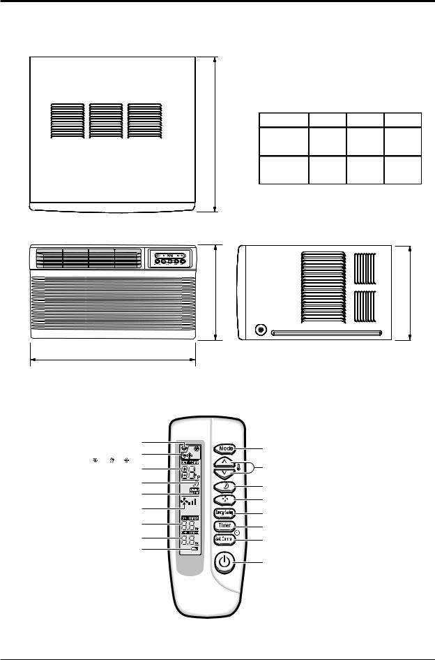
2-2 Dimensions
2-2-1 Main Unit
D
Front view
(Unit : mm)
MODEL |
W |
H |
D |
|
SP06A10 |
520 |
345 |
485 |
|
SP08A10 |
||||
|
|
|
||
SP10A10 |
600 |
394 |
595 |
|
SP12A10 |
||||
|
|
|
Side view
H |
H |
W
2-2-2 Remote Control
Remote control |
|
|
transmission indicator |
Mode selection button |
|
|
|
|
Operating mode |
(Cool, Fan, Dry) |
|
( Cool, Dry, |
Fan) |
|
Temperature setting |
Temperature adjustment |
|
|
|
buttons |
Sleep mode |
Sleep timer setting button |
|
|
||
Energy Saving mode |
Fan speed adjustment |
|
|
||
Fan speed |
button |
|
Energy Saving button |
||
|
||
On Timer setting |
Timer setting button |
|
|
||
Off Timer setting |
Timer Set/Cancel button |
|
|
||
Battery discharge indicator |
|
|
|
On/Off button |
2-4 |
FRIEDRICH AIR CONDITIONING CO. |

3. Installation and Operating Instructions
3-1 Installation
3-1-1 Selecting Area for Installation
1.Make sure that you install the unit in an area providing good ventilation. The air conditioner must not be blocked by any obstacle affecting the air flow near the air inlet and air outlet.
2.Make sure that you install the unit in an area that allow good air handling. The installation area must be able to endure vibration from the unit.
3.Make sure that you install the unit away from heat or vapor.
4.Make sure that you install the unit in an area which is cool and has adequate space.
5.Make sure that you install the unit in an area away from TVs, audio units, cordless phones, fluorescent lighting fixtures and other electrical appliances (obtain a clearance of at least one meter).
6.Make sure that you install the unit in an area which provides easy drainage for condensed water.
7.Make sure that you install the unit in an area not exposed to rain or direct sunlight.
(Install a separate sunblind if exposed to direct sunlight.)
8.Make sure that you install the unit in an area allowing good air movement. Do not install it in a space that would cause noise amplification of noise.
9.Fix the unit firmly if mounted in a high place.
Caution:
Do not use the air conditioner in the following environments : greasy areas (including areas near machines), or marine areas. Contact your local dealer for advice.
FRIEDRICH AIR CONDITIONING CO. |
3-1 |
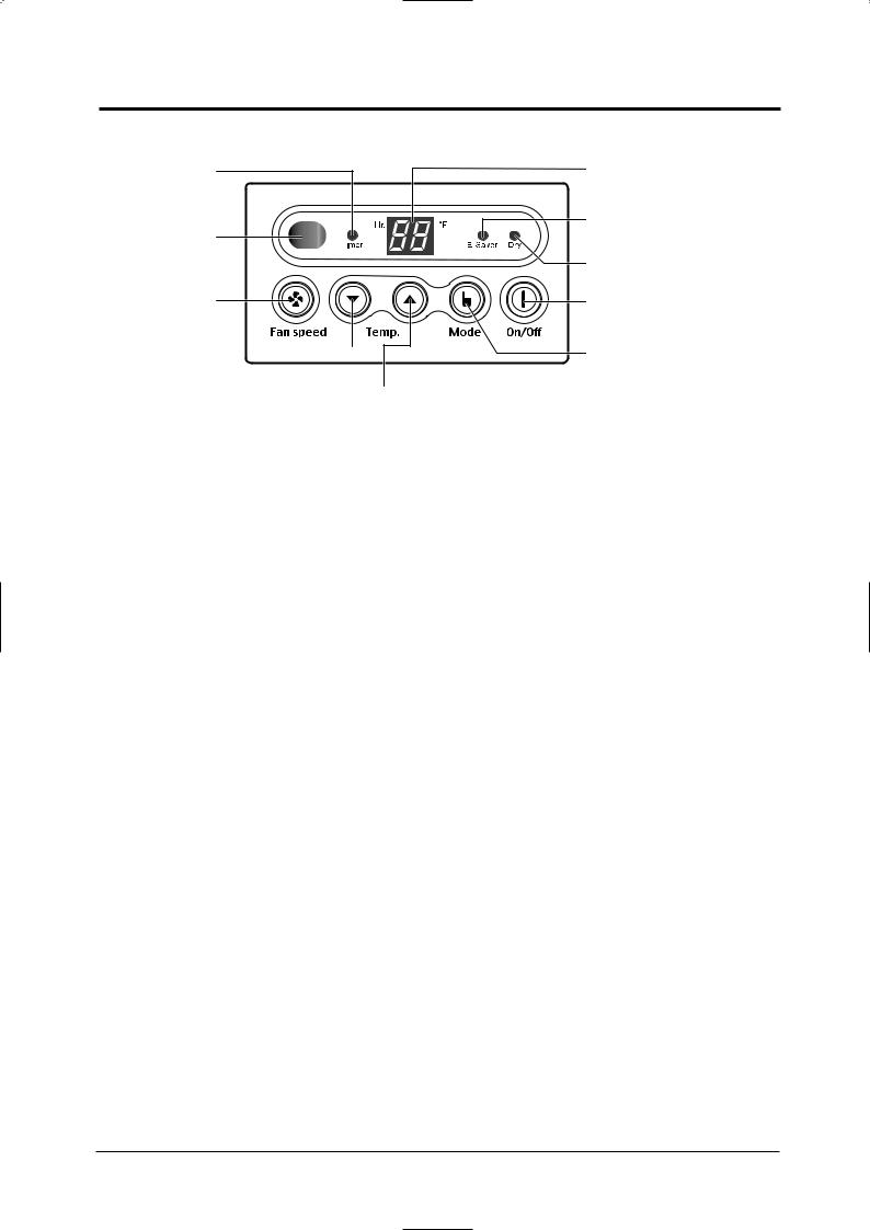
3-2 Function Description
Timer indicator |
Temperature/Timer |
|
settings |
|
Energy Saver indicator |
Remote control |
|
sensor |
|
|
Dry adjustment indicator |
Fan speed |
On/Off button |
adjustment button |
|
|
Mode selection button |
|
(Cool, Fan, Dry) |
|
Temperature |
|
adjustment buttons |
3-2-1 Cooling operation mode
The compressor is turned on and off according to the ambient temperature and set temperature.
1)Compressor on and off control
•Compressor on and off control according to the ambient temperature
*The compressor is turned off when "ambient temperature = set temperature
*The compressor is turned on when "ambient temperature = set temperature +1˚C"
2)Default value after power reset set temperature = 75˚F
Fan speed = High
3) Set temperature indicating (setting) range : 1˚F interval from 64˚F to 86˚F.
3-2-2 Fan operation mode
1)If "Fan operation mode" signal is received from remocon or panel.
the compressor is immediately turned off and only fan motor is operated at set blowing speed.
it changes such as "High Med Low High"( if Fan speed is selected).
2)The initial Fan motor speed is set to "High".
3)The set temperature can not be indicated and set.
3-2-3 Energy saver operation mode
*If the compressor turn off at the cooling operation, the fan motor turn off after operation during the fixation time only, and operation that energy saver by turn off the fixation time only, and operation that energy saver by turn off the motor continuously before the condition of the compressor on.
*The fan motor is not operated at flow wind operation.
*Energy saver operation specification at the cooling operation.
1)Fan motor control in compressor on : operate with setting wind speed
2)Fan motor control in compressor off : After compressor off, the fan motor is operated breeze for 2 minutes and then it turn off.
3)After the fan motor off, the compressor and fan motor is operated normally when the compressor on.
3-2 |
FRIEDRICH AIR CONDITIONING CO. |
Installation and Operating Instructions
3-2-4 Sleep operation mode
1)Enable to sleep operation only when cooling operation.
2)First, 7-SEG LED DISPLAY "SLEEP" while 15 second, Second, 7-SEG LED DISPLAY "8Hr" And, automatically SET OFF after operated while 8 Hour
3)If sleep operation, setting Temperature rise 1˚C after 1 Hour
4)ON TIMER operation, not operation, ENERGY SAVER operation, not sleep operation.
3-2-5 Dry operation mode
If the atmosphere in the room is very humid or damp,use this operation mode. It can remove excess humidity without lowering the room temperature too much.
1) The quantity of air is adjusted automatically.
3-2-6 LED display indication in case of error detection
ERROR OPERATION |
7-SEG |
|
LED DISPLAY |
||
|
||
ROOM THERMISTOR |
E1 displayed |
|
(OPEN or SHORT) |
||
|
1)Set operation in case of error occurrence.
•Malfunction of each temperature sensor (open, short)
-Error mode display, warning sound.
-The operation status is off.
FRIEDRICH AIR CONDITIONING CO. |
3-3 |

MEMO
3-4 |
FRIEDRICH AIR CONDITIONING CO. |
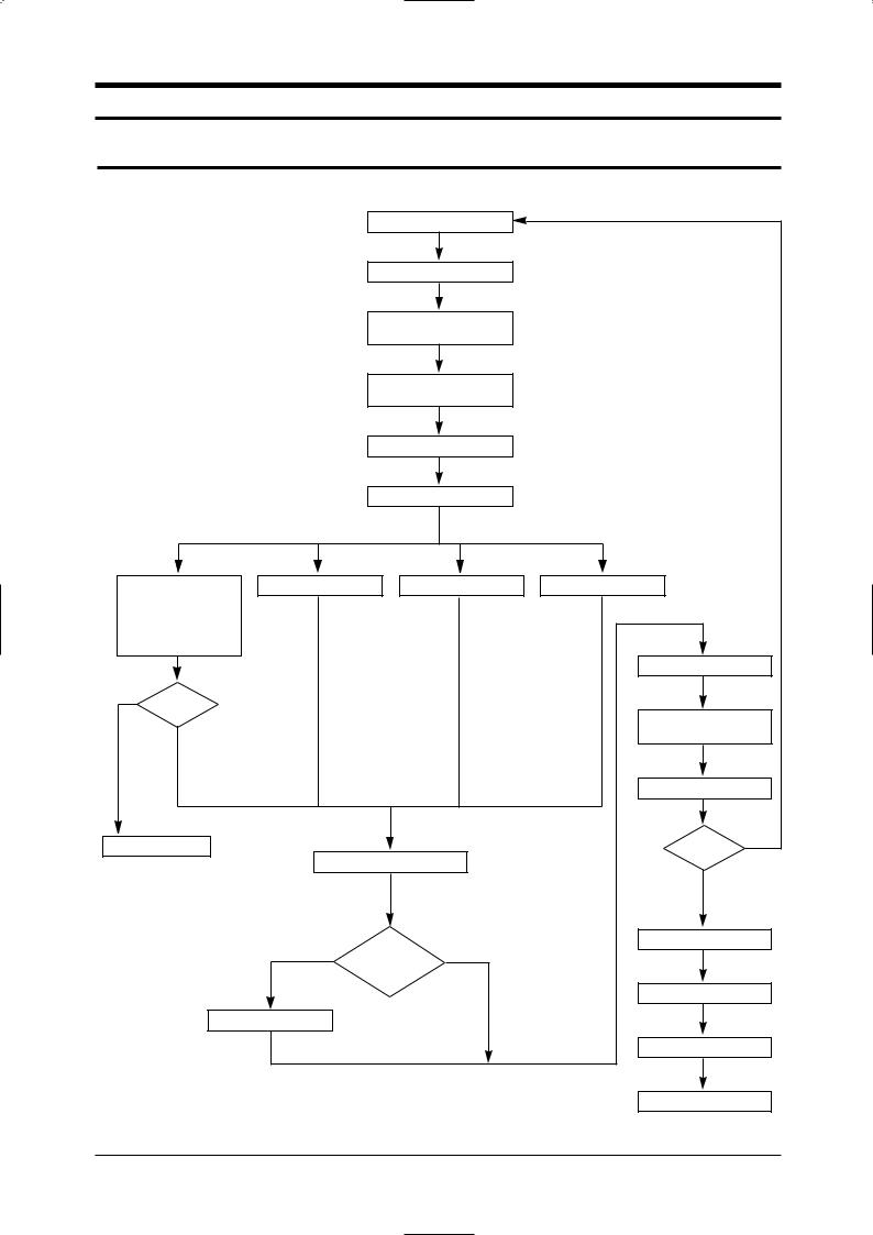
4. Disassembly and Reassembly
4-1 Compressor Replacement Flow Chart
|
|
Locate cause of defect |
|
|
|
Release refrigerant |
|
|
|
Disconnect electrical wiring |
|
|
|
from compressor |
|
|
|
Cut refrigerant lines |
|
|
|
from compressor |
|
|
|
Plug disconnected lines |
|
|
|
Replace compressor |
|
Inspect electrical |
Solder discharge line |
Solder suction line |
Use nitrogen gas |
wiring for defects, |
|
|
|
and terminals for |
|
|
|
correct and secure |
|
|
|
connections |
|
|
|
|
|
|
Perform soldering function |
Y |
|
|
|
Problem? |
|
|
|
|
|
|
Fill system with |
|
|
|
nitrogen gas |
N |
|
|
|
|
|
|
Check for leakage |
Corrective action |
|
|
Y |
Check refrigerant oil level |
Leakage? |
||
|
|
||
|
|
|
N |
Release nitrogen gas?
Y N
Low oil level?
Evacuate system
Add oil as necessary
Recharge system
Pinch and braze filling tube
FRIEDRICH AIR CONDITIONING CO. |
4-1 |
4-2 Checking the oil
Fill the transparent container with 10cc of oil, and then conduct the test.
4-2-1 Oil quality
Condition of |
|
Oil Condition |
Remarks |
|
Refrigerant Cycle |
Color |
|
Odor |
|
|
|
|||
|
|
|
|
|
Normal |
Straw Yellow |
|
No Odor |
Return with the system |
|
|
|
|
|
Over-heated |
Brown Color |
|
- |
Change the oil |
|
|
|
|
|
Compressor Damage |
Dark Brown |
|
Pungent oil |
Change the oil |
|
|
|
|
|
4-2-2 Replacing and refilling the refrigerant oil
1. Change the compressor - DO NOT recharge the oil as the compressor itself is already charged.
2.Change the condenser .... add 50cc
3.Change the evaporator .... add 50cc
4.When the refrigerant is replaced .... add 30cc oil.
5.After vacuum is completed, the oil is filled through the high pressure side.
6.In the event of a refrigerant leak, generally it is not necessary to add oil. (Unless the oil has leaked significantly.)
4-2 |
FRIEDRICH AIR CONDITIONING CO. |
 Loading...