

Page 1
Models PXPC15 / 20 / 30
Installation Instructions
SUB BASE POWER CORD KIT
For use with Packaged Terminal Units installed with an Electrical Sub Base only
Please read these instructions completely before attempting installation.
NOTE: These instructions apply to the installation of the Friedrich Power Cord accessory kits only. This kit is
exclusively for the use of a standard power cord on 230/208V units that are installed with a subbase either for
new or existing installations.
STEP 1
WARNING
Disconnect the electrical power to the unit.
Electrical shock hazard.
Disconnect all power at the unit and the main
disconnect box.
The unit MUST be grounded to the ground
terminal in the main electrical service panel.
Failure to do so can result in personal injury,
property damage, and/or death.
It is the installer’s responsibility to properly apply
and install the equipment. Installation must be in
conformance with the NFPA 70-2002 National
Electric Code or current edition and Universal
Mechanical Code current edition and applicable
local or national codes.
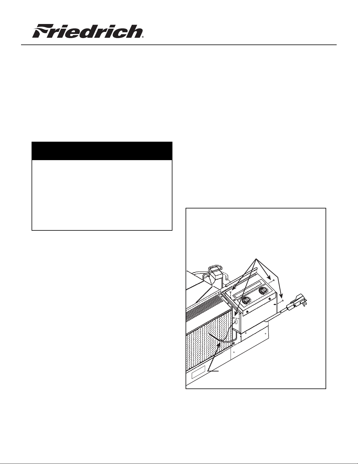
Remove the front cover.
Remove the thermostat bulb from the coil face.
Rotate the control box cover down by removing
the four screws shown in Figure 1.
Figure 1 Rotate the control box down
by removing four screws as
shown below
Control box screws (4)
920-166-00 (5-05)
Pull thermostat bulb off the coil
Page 2
STEP 2A
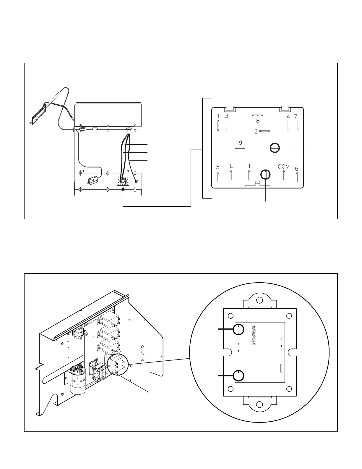
Disconnect Existing Power Cord (Standard Control Models)
Remove the ribbed power cord lead from the L2 terminal on the system switch. Remove the smooth power cord lead from
terminal L1 on the unit system switch. Remove the screw holding the green power cord ground wire on the control box.
Figure 2
Control Box
(Rotated)
System Switch
L1 (smooth)
L2 (ribbed)
Ground
Smooth Cord
L2
Ribbed
L1
STEP 2B
Disconnect Existing Power Cord (Wall Thermostat Control Models)
Remove the ribbed power cord lead from the 240V* terminal on the transformer. Remove the smooth power cord lead from
COM terminal on the transformer. Remove the screw holding the green power cord ground wire on the control box.
Figure 3
Transformer
* For 208V supply power, ribbed cord connects to to 208V terminal
Ribbed
Cord
Smooth
Cord
240V208VCOM
24V
Page 3
STEP 3
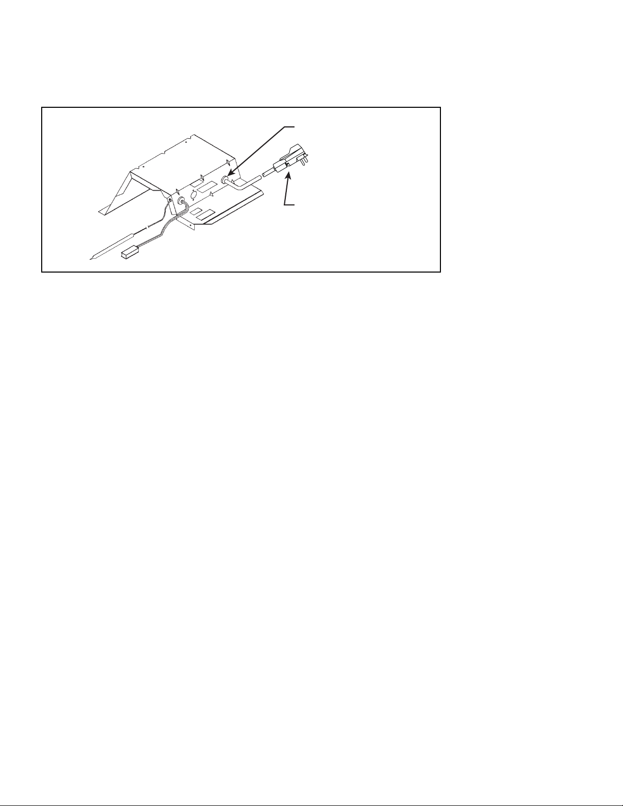
Remove Existing Power Cord from Control Box
From the inside of the control box squeeze the power cord strain relief bushing with a pair of pliers. While squeezing push
the bushing out of the control box and remove the power cord and old bushing.
Figure 4
Strain relief bushing
Existing LCDI Power Cord
15A version shown; others
may be different
STEP 4
Install New Power Cord in Control Box
Insert the female quick connect ends into the control box through the same opening that the old cord was removed. Pull
approximately 6" of the power cord into the control box and reinstall the new strain relief bushing. The bushing folds over
the power cord and snaps into place by pushing from the outside of the box toward the inside. It may be necessary to
use pliers when reinstalling the bushing.
IMPORTANT: The power cord must be inspected for damaged insulation prior to powering the unit on. If any
damage is visible it is imperative that a new cord be installed.
STEP 5A
Connect New Power Cord (Standard Control Models)
Connect the ribbed power cord lead to the L2 terminal on the system switch. Connect the smooth power cord lead to
terminal L1 on the unit system switch. Connect the green power cord ground wire to the control box.
STEP 5B
Connect New Power Cord (Wall Thermostat Control Models)
Connect the ribbed power cord lead to the 230-V terminal on the transformer. Connect the smooth power cord lead to
COM terminal on the transformer. Connect the green power cord ground wire to the control box.
STEP 6
Make sure that all the wires are connected inside the control box. Rotate the box back to its original position and
reinstall the four screws.
STEP 7
• Reinstall the thermostat bulb on the coil face.
• Reinstall the front cover.
• Restore power.
• Plug cord into sub base receptical.
• Check for proper operation.
Page 4

FRIEDRICH AIR CONDITIONING CO. INC.
Post Office Box 1540 · San Antonio, Texas 78295-1540
4200 N. Pan Am Expressway · San Antonio, Texas 78218-5212
(210) 357-4400 · FAX (210) 357-4480
www.friedrich.com
Printed in the U.S.A.
920-166-00 (5-05)
 Loading...