

Page 1
PTAC
Packaged Terminal Air
Conditioners & Heat Pumps
Installation and Operation Manual
FreshAire
TM
Page 2

2
Tableof Contents
Congratulations········································································································································3
General Instructions
General Specifications
PTAC Installation Recommendations···········································································································5
Wall Sleeve Installation Instructions (PDXWSA)···························································································· 6
Alternate Wall Installations
PXDR10 Drain Kit Installation Instructions (optional for new construction)
External Drain (for new construction or unit replacement)··············································································11
PXGA Standard Grille Installation Instructions····························································································· 12
Chassis Install Preparation
Chassis Installation
Friedrich PTAC Digital Control and Unit Features·························································································19
System Configuration······························································································································ 21
Digital Control User Input Configuration
Digital Control Operation
Remote Control Thermostat Installation······································································································26
··································································································································
·······························································································································
·························································································································
························································
·······················································································································
·································································································································
······································································································
··························································································································
10
16
18
22
24
3
4
7
Remote Thermostat and·························································································································· 26
Low Voltage Control Connections
Final Inspection & Start-up Checklist
Basic Troubleshooting····························································································································· 29
Service & Assistance·······························································································································31
Accessories
···········································································································································
··············································································································
··········································································································
26
28
32
NOTE:
All PTAC 9000units come with a universal 2.5+1.0kW electric heater(standard 20A power cord for 3.5kW ,optional
15A power cord for 2.5kW). All PTAC 12000units come with a universal 3.5+1.5kW electric heater(standard 20A
power cord for 3.5kW,optional 30A power cord for 5kW,optional 15A power cord for 1.5kW).
Page 3
3
Congratulations
Thank you for your decision to purchase Friedrich. Your new Friedrich has been carefully engineered and manufactured to give you many years of
dependable, efficient operation, maintaining a comfortable temperature and humidity level. Many extra features have been built into your unit to assure quiet
operation, the greatest circulation of cool, dry air, and the most economic operation.
This Installation and Operation Manual has been designed to insure maximum satisfaction in the performance of your unit. For years of trouble-free service,
please follow the installation instructions closely. We cannot overemphasize the importance of proper installation.
WARNING
Refrigeration system
under high pressure
Do not puncture, heat, expose to flame or
incinerate.
Only certified refrigeration technicians should
service this equipment.
R410A systems operate at higher pressures
than R22 equipment. Appropriate safe
service and handling practices must be used.
Only use gauge sets designed for use with
R410A. Do not use standard R22 gauge sets.
Here are some suggestions to help you use your
new Friedrich most efficiently:
1. Carefully read and follow the installation instructions.
2. Make sure the unit is the right capacity for the area being cooled.
An undersized unit makes the unit work too hard, using more
electricity than needed and increases wear. An oversized unit
will cycle on and off too rapidly, and therefore cannot control
humidity as well.
3. Clean the filter frequently (See Routine Maintenance, Page 27).
4. Do not block the air flow to and from the unit.
5. A dirty filter or improperly set controls can affect the cooling
ability of the unit.
6. If cooling is weak and you have verified that the filter is clean
and the controls are properly set, the unit may need service and
you should call your Friedrich service provider to check the unit.
7. Keep blinds, shades and drapes closed on the sunny side of the
room being cooled to reduce radiant heat.
8. Proper insulation helps your unit maintain the desired inside
temperature.
9. Whenever possible, shade south and west facing windows.
10. Keep window coverings awayfrom the unit to provide free airflow.
WARNING
Read Installation Operation Manual
Please read this manual thoroughly prior to
equipment installation or operation.
It is the installer’s responsibility to properly
apply and install the equipment. Installation
must be in conformance with the NFPA 70
-2008 National Electric Code or current edition,
International Mechanic Code 2009 or current
edition and any other applicable local or
national codes.
Failure to do so can result in property damage,
personal injury or death.
WARNING
CAUTION
Indicates a hazard which, if not avoided, can result in severe personal injury or
death and damage to product or other property.
Indicates a hazard which, if not avoided, can result in personal injury and
damage to product or other property.
NOTICE
Indicates property damage can occur if instructions are not followed.
General Instructions
Your safety and the safety of others are very important.
We have provided many important safety messages in this manual and on your appliance. Always read and obey all
safety messages.
This is a safety Alert symbol.
This symbol alerts you to potential hazards that can kill or hurt you and others.
All safety messages will follow the safety alert symbol with the word “WARNING”
or “CAUTION”. These words mean:
All safety messages will tell you what the potential hazard is, tell you how to reduce the chance of injury, and tell you
what will happen if the instructions are not followed.
Page 4
4
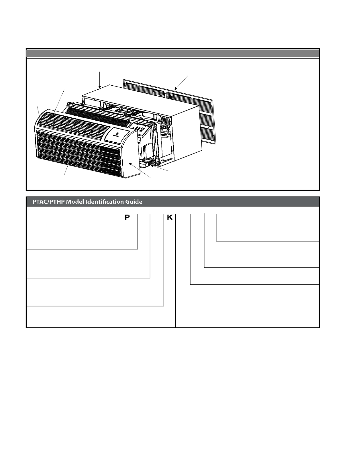
GeneralSpecifications
WALL SLEEVE
DISCHARGE GRILLE
FILTERS
RETURN AIR GRILLE
OUTDOOR GRILLE
CHASSIS
FRONT COVER
PDXWS Wall Sleeve
Dimensions: 16" H x 42" W x
13-¾" D
Front Cover Dimensions:
16" H x 42" W x 7-¾" D
Cut-Out Dimensions:
16-¼" x 42-¼"
MODEL NUMBER
V
H
09
3 F
Series
PV = Friedrich Digital PTAC
System
E = Cooling with electric heat
H = Heat Pump with Auxiliary Heat
Nominal Capacity
Engin eering Digit
Design Series
Chassis
F= FreshAire
07 = 7,000 Btuh
09 = 9,000 Btuh
Voltage
12= 12,000 Btuh
15= 15,000 Btuh
Nominal Heater Size (230V or 265V)
3=3kW
Installation Checklist
. Inspect all components and accessories for damage before and
after installation.
. Remove the cardboard wall sleeve support and grill weatherboard.
. Check for proper wall sleeve installation in accordance with the wall
sleeve installation instructions.
. Check for a subbase kit or other means of structural support which
is required for ALL installations projecting more than 8" into room.
. Install th e recommended Condensate Drain Kits for complete
condensate removal.
. Ensure that chassis and chassis front cover are installed and secured
properly.
. Ensure that drapes,bed,bedspread,furniture,etc DO NOT block
either return or discharge air grilles.
. Inspect the condenser air inlet and outlet for any obstructions
(shrubbery,etc).
. Ensure that 'reset' button is pressed on LCD device(only on cord
connected models).
Typical Unit Components and Dimensions
K = 230/208V - 1 Ph. - 60 Hz.
R = 265V - 1 Ph. - 60 Hz.
A
. Ensure that the chassis is installed in a 16" highx4'' wide wall sleeve
that is no deeper than 13-¾".A baffle kit is required if the sleeve
exceeds that depth.
Page 5
5
PTACInstallationRecommendations
FRP001
• Fo r mi nor o bs truc t ion s
such as lamp poles or small
shrubbery a clearance of
12" from the outdoor louver
should be maintained.
TYPICAL BUILDING ( PLAN VIEW )
• For major obstructions such
as a solid fence, wall or
other heat rejecting device
like a condensing unit, a
minimum distance of 36"
should be kept.
PTAC
12" MINIMUM, MINOR
OBSTRUCTIONS
36" MIMUMUM, MAJOR
36"
POLE
PTAC
12"
36"
36"
SHRUB
PTAC
OBSTRUCTIONS
CONDENSING UNIT
FENCE OR WALL
FRP002
The above suggestions are for reference only and do not represent all possible installations.Please contact Friedrich for information regarding affects of other
installation arrangements.By following these simple recommendations youcan be confident that your Friedrich PTACwill provide years ofworry free operation.
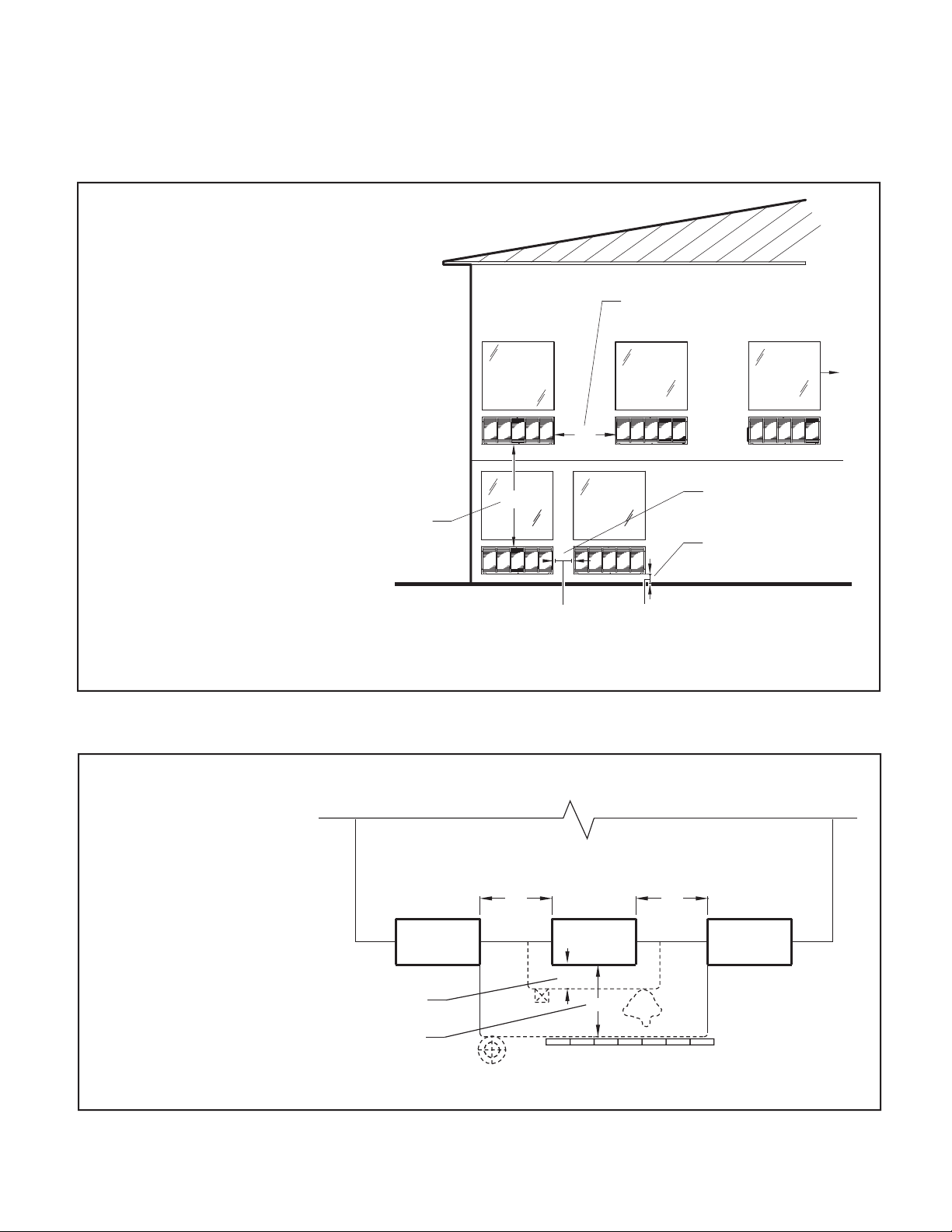
For proper PTAC unit performance and maximum operating life refer to the minimum installation clearances
below:
Figure 1
PTAC units should be installed no
closer than 12" apart when two
units are side by side. If three or
more PTAC units are to operate
next to one another allow a
minimum of 36" between units.
Also,a vertical clearance of 60"
should be maintained between
units installed. In the interior of
the room the unit should be
located a minimum of 1/4" from the
floor and a minimum of 36"
from the ceiling.
TYPICAL
WINDOW
36"
THREE OR MORE PTACs
ADJACENT 36" MINIMUM
TWO ADJACENT PTACs
12" MINIMUM
GROUND FLOOR PTACs
6" MINIMUM FROM GRADE
60" VERTICAL
MINIMUM
BETWEEN
PTACs
60"
12"
6"
VIEW: OUTSIDE BUILDING ELEVATION
For PTACs on the ground floor or anytime obstructions are present, use the following guidelines:
Figure 2
Page 6
6
Wall Sleeve Installation Instructions (PDXWSA)
NOTE: Insure that the unit is only installed in a wall structurally adequate to support the unit including the sleeve, chassis and accessories.If the sleeve
projects more than 8" into the room, a subbase or other means of support MUST be used. Please read these instructions completely
before attempting installation.
WARNING
Falling Object Hazard
Not following Installation Instructions for
mounting your air conditioner can result
in property damage, injury, or death.
NOTICE
DO NOT allow any pitch toward the inside.
Flashing on all 4 sides of the opening is recommended.
Potential property damage can occur if instructions are
not followed.
For Deep Wall Installation (Greater than 13 1/4")
See Page 9
The following instructions apply ONLY to walls less than 13 ¼" in depth.
1 The PXDR10 Drain Kit,(optional for new construction) see page 10
if applicable, must be installed before the wall sleeve is installed
into the wall.
2 The External Drain (for new construction or unit replacement) see
page 11 if applicable, must be installed before the wall sleeve is
installed into the wall.
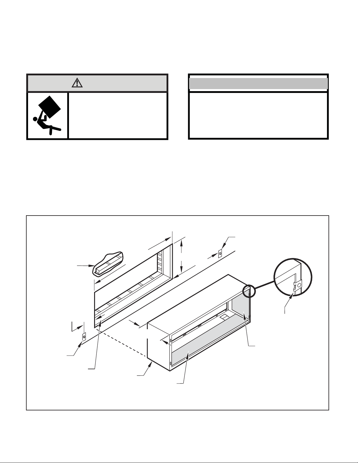
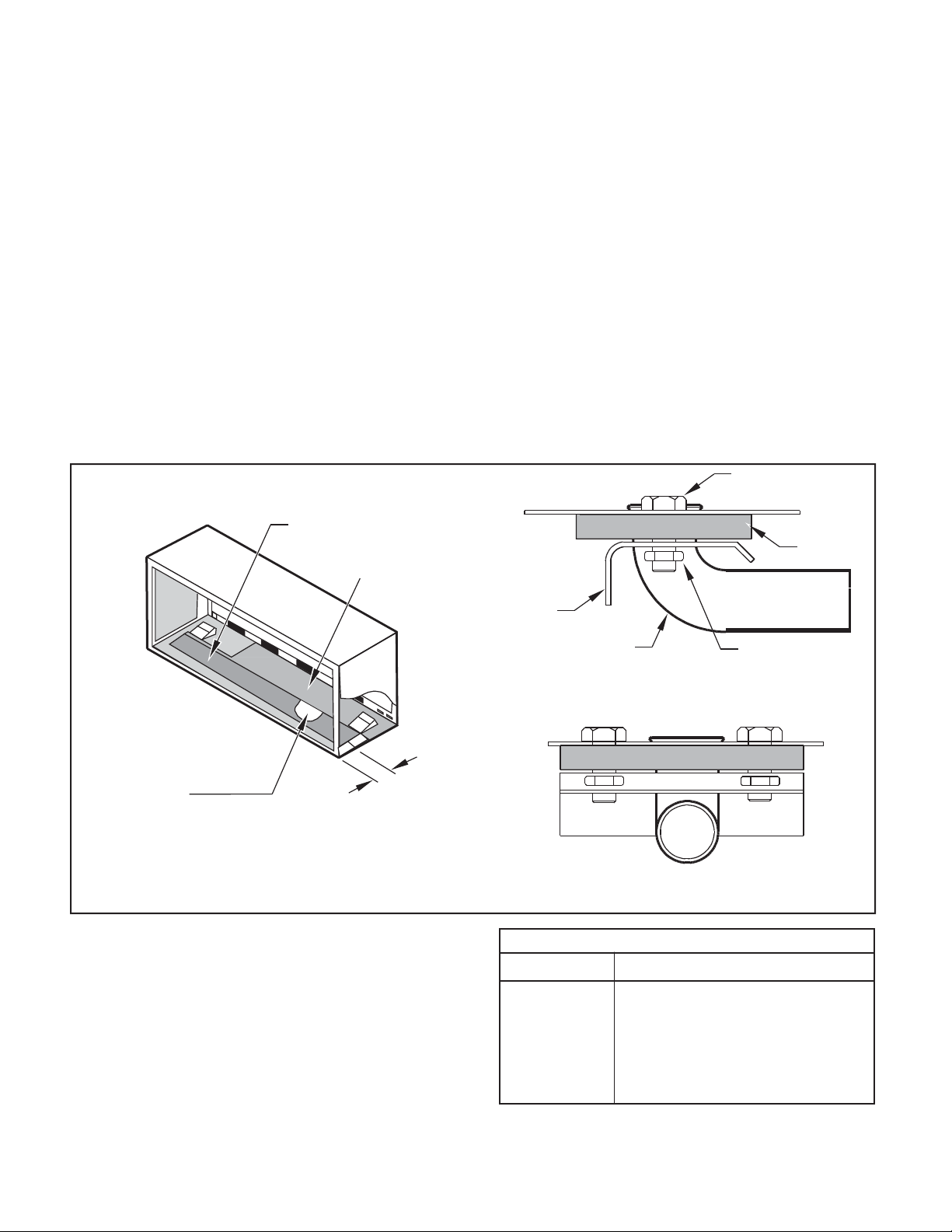
Figure 3
Typical Wall Sleeve Installation
3 Frominside the building, positionthe wall sleeve inthe opening and
push itinto the wall until it protrudes at least ¼” on the outside
(See Figure 9, Page 8).
4 Position the wall sleeve with a slight tilt towards the outside to
facilitate condensate drainage. It should be level side-to-side and
the front should be ¼ bubble higher than the back.
ELECTRICAL
RECEPTACLE
LINTEL TO SUPPORT
MASONRY WALLS
42-¼"
MIN.
16-¼"
60"
MAX.
20"
MAX.
13-¾"
SMOOTH SIDE OF SCREW
CLIP FACING INTO ROOM
ELECTRICAL
RECEPTACLE
INSULATION
WALL OPENING
WALL SLEEVE
INSULATION
NOTE:
All 230/208V units are manufactured with a 60” power cord and all 265V units with a 18” power cord.
FRP003
Page 7
7
AlternateWall Installations
Figure 4
Panel Wall
Figure 6
CurtainWall
WALL OR
WINDOW
1/4" MIN
PROJECTIO
N
CASE FLANGE
OPTIONAL SUBBASE
LEVELING SCREW
OPTIONAL SUBBASE
FRP004
LEVELING SCREW
FRP006
Figure 5
Frame and Brick Veneer
Figure 7
Block and Brick Veneer
1/4" MIN
PROJECTION
1/4" MIN
PROJECTION
WOOD FRAME
CONCRETE LINTEL
STEEL
LINTEL
13-3/4" MIN.
STEEL
LINTEL
11" MIN.
WITH SUBBASE
WITHOUT SUBBASE
OPTIONAL SUBBASE
LEVELING SCREW
FRP005
RECEPTACLE
FINISHED FLOOR
POWER SUPPLY CONDUIT
(SUPPLIED BY INSTALLER)
FRP007
NOTE: Follow all wall system manufacturer installation instructions. For sunrooms and modular buildings, adhere to their installation instructions for
supporting and sealing sleeve to their frames. All wall and window/wall installations must provide for proper drainage. In applications where the
drain holes on the PTAC wall sleeve are not exposed beyond the wall an internal drain system is recommended. It is the installer's responsibility
to ensure there is adequate drainage for the PTAC unit.
(BY OTHERS)
Page 8
8
13-¾
"
Figure 8
WALL
SLEEVE
ALTERNATE
FASTENING METHODS
(Field Supplied)
WOOD SCREW
TOGGLE BOLT
NOTE: The Wall Sleeve must be
horizontally level (side-to-side)
and pitched 1/4 bubble to the
outside when installed in an
opening.
The mounting hole location
EXPANSION
ANCHOR BOLT
should be approximately 2-4”
from the top and bottom of the
sleeve.
PLASTIC ANCHORS
SCREWS
FRP008
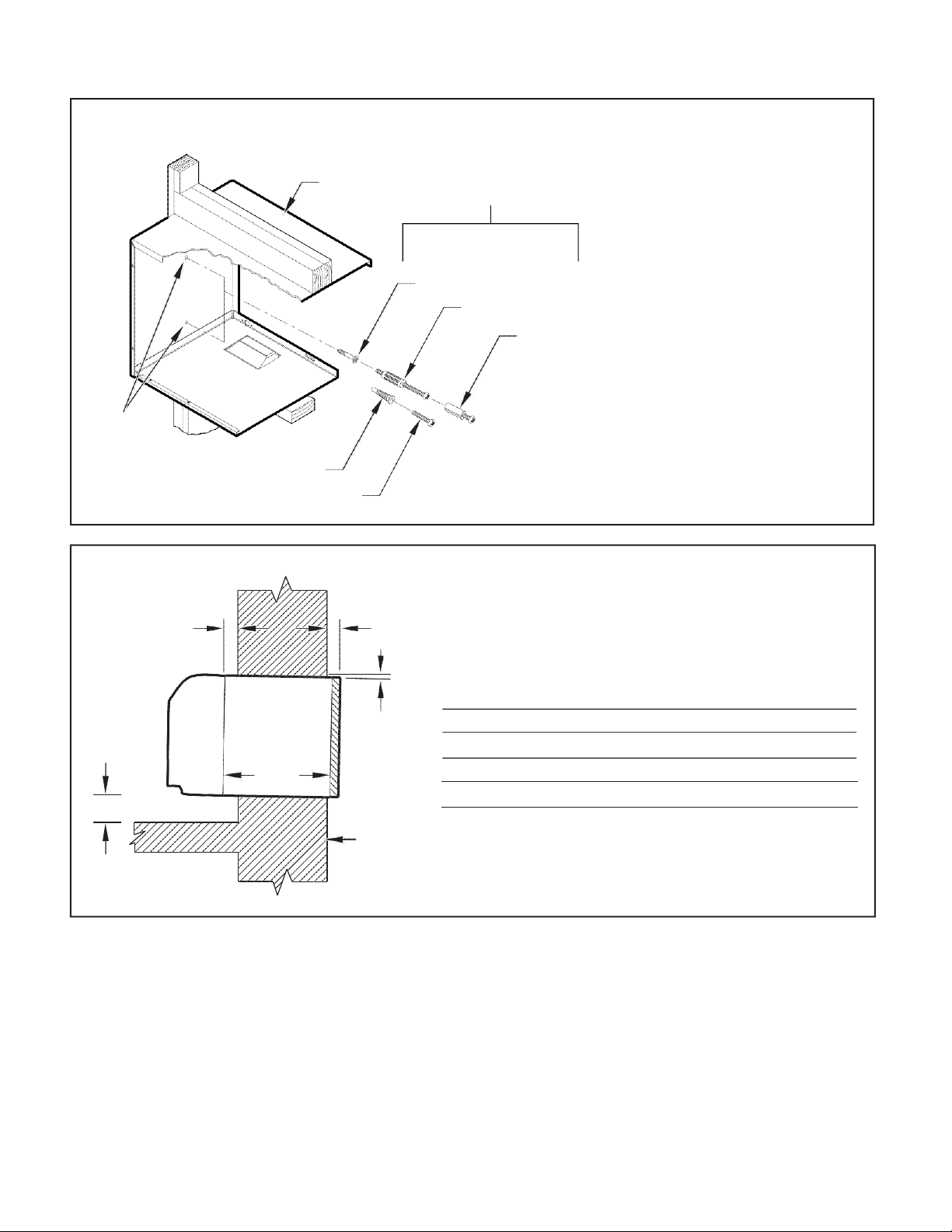
A ¼" MIN.
A B C
Dimension*
Allow
for wall
finishing
Allow
for floor
finishing
Allow
for proper
drainage
(Minimum) Min. Max.
(Front-to-Back)
C
No Accessories
¼" ¼"
---
---
With Subbase 1-¾" 3-½" 5"
---
With Lateral Duct ¾"
¼"
---
---
Wall Sleeve Tilt
B
---
---
---
¼"
WALL
* If more than one accessory is to be used, use the maximum
dimension. If the wall thickness is more than 13-¾" - (A+ ¼"),
a sleeve extension must be used.
Wall Sleeve Attachment
MOUNTING
HOLES
Figure 9
Dimensions
FRP009
Page 9
9
5. Drill two 3/16" holes through each side of the sleeve approximately
4" from top and 4" from bottom of sleeve. Screw four #10 x 1"
screws (included) or appropriate fasteners for your installation,
through the holes in the sides of the wall sleeve.
6. Apply sealant around the wall sleeve where it projects through the
inside and outside wall surfaces. Apply the sealant to the screw
heads or the tops of the fasteners used in Step #5.
7. If the chassis and exterior grille are to be installed later, leave the
weatherboard and center support in place, otherwise remove and
dispose of them. (See Figure 13, Page 12).
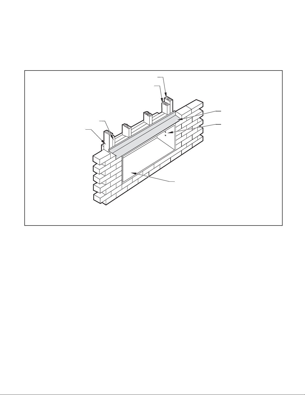
8. Provide a support lintel if the wall sleeve is installed in a concrete
or masonry wall (See Figure 10, Page 9).
Figure 10
Lintel Installation
MAIN STUDS
JACK STUDS
JACK STUDS
MAIN STUDS
LINTEL
MOUNTING
SCREW HOLES
NO HOLES IN BOTTOM OF WALL
SLEEVE UNLESS DRAIN KIT IS USED
NOTE: Construct wall opening to comply with all applicable building codes.
FRP010
One-Piece Deep Wall Sleeve
If the wall is thicker than 13 1/4” a deep wall sleeve or wall sleeve extension
MUST be used. The deep wall sleeve may be special ordered through
your Sales Representative.
Installation (PDXWSEXT)
Page 10
10
PXDR10DrainKitInstallation
Instructions(optionalfornew
construction)
NOTE: Determine whether drain will be located within the wall, on the
indoor side, or will drain to the exterior of the building. Follow
appropriate instructions below depending on your particular
type of installation.
Internal Drain
NOTE: If installing an internal drain, you MUST install a drain kit on
the wall sleeve before the wall sleeve is installed.
1. Refer to Figure 11 and locate the drain within the “Preferred”
area of best drainage.Maintain at least a ½” clearance from the
embossed area.
2. Using the mounting plate with the ½” hole as a template, mark
and drill two, 3/16” mounting holes and a ½” drain hole in the
sleeve bottom.
Figure 11
DrainKitLocationand Installation
OPTIONAL AREA
PREFERRED AREANO FOAM INSULATION
3. Remove the backing from the gasket and mount it on the flat
side of the mounting plate (See Figure 12, Page 11). Insert the
drain tube through the hole in the gasket and mounting plate so the
tube flange will be against the wall sleeve.
4. Position the assembly beneath the drilled holes and secure it with
#10-24 x ½" machine screws and lock nuts provided. Seal the tops
of the screws with silicone caulking.
5. Use ½" I D copper tube, PVC pipe, or vinyl hose (obtained locally)
to connect the internal drain tube tothe drain system in thebuilding.
6. Referring to Figure 12, Detail A, Page 11, locate and assemble
the two cover plates and gaskets over the drain holes at the
rear of the wall sleeve. Attach them with the #10 sheet metal
screws provided. Make certain that the four overflow slots at
the rear of the wall sleeve are not blocked (See drawing of the
back of the sleeve Figure 12, Page 11).
7. If a deep wall extension (PDXWSEXT) is used, after installing the
field supplied flashing,caulk as required. Be sure to caulk around
the flashing and the wall sleeve where the hole was drilled for the
drain tube.
DRAIN TUBE
NUT
IF THE DRAIN MUST BE
REMOVED TO ALLOW ACCESS
3"
FRONT VIEW
FRP011
PXDR10
QUANTITY
DESCRIPTION
2
COVER PLATES
1
MOUNTING PLATE
1
DRAIN TUBE
3
MOUNTING PLATE GASKET
4
#10 X ½” SHEET METAL SCREWS
2
#10-24 X ½ ” MACH. SCREWS
2
#10-24 X ½" LOCKNUTS
LOCATED IN THE OPTIONAL
AREA, THE FOAM INSULATION
MUST BE CUT AWAY AND
TO THE DRAIN.
WALL SLEEVE
SCREW
GASKET
MOUNTING
PLATE
SIDE VIEW
Page 11
11
External Drain (for new
construction or unit
replacement)
When using an external drain system, the condensate is removed through
either of two drain holes on the back of the wall sleeve. Select the drain
hole which best meets your drainage situation and install the drain kit.
Seal off the other with a cover plate.
Drain Tube Installation (See Figure 12)
1. Peel the backing tape off the gaskets and apply the sticky side
to one cover plate and one mounting plate as shown in Details
A and B.
2. Place the drain tube through the gasket and the mounting plate
with the flange toward the wall sleeve.
3. Attach the drain tube assembly to one of the two drain holes at the
rear of the wall sleeve. The large flange on the mounting plate is
positioned at the bottom of the sleeve facing toward the sleeve,
Detail B. When the drain tube is positioned at the desired angle,
tighten the screws.
Cover Plate Installation
4. Mount the foam gasket tothe cover plate. Using two #10 x ½" sheet
metal screws (provided), attach the cover plate to the remaining
drain hole. Make certain the large flange on the plate is positioned
at the bottom of the sleeve.
5. Discard the additional cover plate, gasket, machine screws, and
locknuts.
NOTICE
If the wall sleeve has not been installed, the drain tube
must be rotated to a horizontal position until after the
sleeve is installed. Tighten the mounting plate screws
when the tube is in the proper position. Make certain that
the four overflow slots at the rear of the wall sleeve are not
blocked (See Figure 12).
When sealing the sleeve on the outside of the building, be
careful NOT to let the sealant block the two condensate
drain holes or the four overflow slots at the bottom flange
of the sleeve.
Potential property damage can occur if instructions are
not followed.
Figure 12
Drain Kit Installation
COVER
PLATE
NUT
MOUNTING
PLATE
FOAM
GASKET
DETAIL A
FOAM
GASKET
DETAIL B
SCREWS
½” O.D. TUBE
FRP012
NOTE: The large flange on the mounting plate is positioned at the bottom of the sleeve facing toward the sleeve. The drain tube must be rotated to a
horizontal position to allow for the wall sleeve to be installed into the wall. Once the wall sleeve is installed, return the drain tube to a downward
angle.
OVERFLOW
SLOTS
Page 12

12
PXGA Standard Grille
Quantity
Description
1
6
6
Stamped Aluminum Grille
Plastic Grommets
#8 x –" Sheet Metal Screws
PXGAStandardGrille
Installation Instructions
1. Remove the center support and weatherboard if still installed in
the sleeve.
2. Insert six plastic grommets into the grille openings from the outside
of the grille as shown in Figure 13.
3. Insert two #8 x ⅜" sheet metal screws (provided) in the top two
outside edge plastic grommets, and tighten them half way into
the grommets.
4. Grasp the grille by the attached plastic handles. Pos ition
it w ith t he c ond e nsa te d rai n kno c ko uts f aci ng d own.
From inside the building, maneuver the grille through the wall
sleeve and pull toward you until the screw heads are inserted
into the keyhole slots at the top of the wall sleeve. Tighten the
two screws completely.
5. Insert the remaining screws into the remaining holes and tighten
securely.
WARNING
Falling Object Hazard
Not following Installation Instructions for
mounting your air conditioner can result
in property damage, injury, or death.
Figure 13
WEATHERBOARD
CENTER SUPPORT
WALL
SLEEVE
STANDARD
GRILLE
#8 x 3/8”
SHEET METAL
SCREW
Standard Grille
WALL SLEEVE
STANDARD GRILLE
PLASTIC GROMMETS
PLASTIC HANDLES
FRP013
Page 13

13
FUSE/CIRCUIT
BREAKER
Use ONLY type and size fuse or HACR circuit breaker indicated on unit’s rating plate.
Proper current protection to the unit is the
responsibility of the owner. NOTE: A time
delay fuse is provided with 265V units.
GROUNDING
Unit MUST be grounded from branch circuit through service cord to unit, or through
separate ground wire provided on permanently connected units. Be sure that branch
circuit or general purpose outlet is grounded.The field supplied outlet must match plug on service cord and be within reach of
service cord. Refer to Table 1 for proper
receptacle and fuse type. Do NOT alter
the service cord or plug. Do NOT use an
extension cord.
RECEPTACLE
A.
Table 1 Receptacles and Fuse Types
Voltage
230V
265V
Amps
152030
152030
Heater Size
3.5kw
5kw
5kw
Receptacles
NEMA#
Receptacle
6-15R
6-20R
6-30R
7-15R
7-30R
NEMA#
Plug
6-15P
6-20P
6-30P
7-15P
7-30P
electrician and conform to the National
Code and all local codes which have
jurisdiction.
B. Power Cord Information (230/208V models only)
All Friedrich 230/208V PTAC units are shipped from the factory with a
Leakage Current Detection Interrupter (LCDI) equipped power cord.
The LCDI device meets the UL and NEC requirements for cord connected
air conditioners effective August 2004.
To test your power supply cord:
1. Plug power supply cord into a grounded 3 prong outlet.
2. Press RESET.
3. Press TEST ( listen for click;Reset button trips and pops out).
4. Press and release RESET (listen for click;Reset button latches
and remains in).The power supply cord is ready for operation.
Figure 14
Typical LCDI Devices
NOTE: The LCDI device is not intended to be used as a switch. Once
plugged in the unit will operate normally without the need to reset the
LCDI.device.
If the LCDI device fails to trip when tested or if the power supply cord is
damaged it must be replaced with a new supply cord obtained from the
product manufacturer,and must not be repaired.
15/20/30A LCDI Device
FRP014
Electrical Rating Tables
All units are equipped with standard power cords.
NOTE: 1.5kW heater only for 12K Btu unit and 2.5kW heater only for 9K Btu unit.
1.5/2.5kw
1.5/2.5kw
WARNING
Electrical Shock Hazard
Turn off electrical power before service
or installation.
ALL electrical connections and wiring
MUST be installed by a qualified
Failure to do so can result in property
damage, personal injury and/or death.
3.5kw
7-20R
7-20P
The field supplied outlet must match plug on
service cord and be within reach of service
cord. Refer to Table 1 for proper receptacle
and fuse type. Do NOT alter the service
cord or plug. Do NOT use an extension
cord.
Page 14

14
TABLE 2
MODEL
HEATER kW
Power Cord Kit
Voltage
Amperage
Receptacle
PVH09K
2.5(optional)
STD
230/208
15
NEMA 6-15r
3.5(default)
STD
230/208
20
NEMA 6-20r
PVH12K
1.5(optional)
STD
230/208
15
NEMA 6-15r
3.5(default)
STD
230/208
20
NEMA 6-20r
5.0(optional)
STD
230/208
30
NEMA 6-30r
PVH09R
2.5(optional)
STD
265/277
15
NEMA 7-15r
3.5(default)
STD
265/277
20
NEMA 7-20r
PVH12R
1.5(optional)
STD
265/277
15
NEMA 7-15r
3.5(default)
STD
265/277
20
NEMA 7-20r
5.0(optional)
STD
265/277
30
NEMA 7-30r
Electrical Wiring for 265 Volt Models
Power Cord Installation
All 265V PTAC/PTHP units come with a factory installed non-LCDI
power cord for use in a subbase.If the unit is to be hard-wired refer to
the instructions below.
NOTE: It is recommended that the PXSBsubbase assembly, the
PXCJA conduit kit(or equivalent) be installed on all
hardwire units.If installing a flush-floor mounted unit,make
sure the chassis can be removed from the sleeve for
service and maintenance.
Toinstall the line voltage power leads and conduit to
chassis, follow the instructionsbelow. PXCJA
Conduit Kit isrequiredwiththissetup.
1. Follow the removal process of the chassis’s junction box .
2. Prepare the 265V(or 230V)power cord forconnection to the chassis’
power cord connector by cutting the cord to the appropriate length
(referto Figure16 and follow Figure15).Power cord harness selection
shown on Table 2 on page 14.
WARNING
Electrical Shock Hazard
Turn off electrical power before service
or installation.
ALL electrical connections and wiring
MUST be installed by a qualified
electrician and conform to the National
Code and all local codes which have
jurisdiction.
Failure to do so can result in property
damage, personal injury and/or death.
Page 15

15
Figure 15
4.0 IN.
WALL CONNECTION
JUNCTION
BOX
EXPOSE
WIRES
(1.0 IN.)
18.0 IN.
JUNCTION
BOX COVER
COVER
SCREW
S
FRP016
TRIM HARNESS
TO LENGTH
Figure 17
STRIP WIRE ENDS (0.5 IN.)
SPACER
LEADING SIDE FOR
WIRE HARNESS INSERTION
LOCKNUT
TO WALL JUNCTION
FRP015
3. Route the cut ends of harness through the conduit connector
assembly and flex conduit sleeve. Be sure to use the s upplied
conduit bushing to prevent damage to the cord by the con duit.
The cord should pass through the Locknut, Spacer, Chassis
Junction Box, Conduit Connector, Bushing, then the Conduit
Sleeve. See Figure 17.
4. Route the cut ends of the power cord through the elbow connector
at the other end of the conduit. Tighten screws on elbow connect
or to secure conduit sleeve.
5. Fasten and secure the elbow connector to the wall junction box
cover with locknut. Place and mount the wall junction box with
the four wall mounting screws making sure to pass the wall lines
through the junction box. Connect and join all wall lines with the
stripped ends using wire nuts. Tighten both screws of the wall
junction box cover to junction box.
SPACER
BUSHING
CONDUIT
SLEEVE
EXITING SIDE FOR
WIRE HARNESS
CHASSIS
JUNCTION
BOX
CONDUIT
CONNECTOR
FRP017
Figure 16
TO CHASSIS JUNCTION
STRAIGHT
CONNECTOR
GROUND
SCREW
GROUND
WIRE
HARNESS
Page 16

16
Chassis Install Preparation
1. Remove the weatherboard and center support from the sleeve (if
still in place). Be sure an outdoor grille is attached.
Figure 18
NOTE: To avoid breaking the door orhingepins,do not apply excessive
force when installing.
Figure 19
WALL SLEEVE
PIN
CONTRO
L DOOR
CENTER SUPPORT
FRP018
FRP019
NOTE: Use a wall sleeve adapter kit (PXSE) if installing a P-Series
chassis in a T-Series sleeve.
WARNING
IMPORTANT: When installing a Friedrich PTAC into an existing sleeve,
it is important to ensure that the unit is installed completely. Inspection
of the air seal between the condenser air baffles and around the indoor
mounting flange is recommended.
In some cases additional gaskets or baffling may be required.
Do NOT use in cribs, beds or playpens.
Destroy immediately after opening. This bag
is NOT a toy.
Failure to do so can result in personal injury
and/or death.
2. Remove the front cover contained in a protective plastic bag
from chassis. Remove the bag and dispose of it properly.
a. From the front cover, slide the right control door pin into the
hole on the right side of the front cover.
b. Slide the left door pin into the hole on the left side of the
front cover opening.
c. Snap cover into place.
Checkto besure the wallsleeve,extension (ifused),grille, and drain kitareinstalled properly beforechassis
installation.
INSERT PIN
IN THIS LOCATION
WEATHERBOARD
Suffocation Hazards
Keep bag away from babies and children.
If the control door is not installed, follow these steps:
Page 17

17
CAUTION
Unit Damage Hazard
Failure to follow this caution may result in equipment damage
or improper operation.
3. Carefully remove shipping tape from the front panel and power
vent door. See Figure 20.
Figure 20
SHIPPING TAPE
FRP020
Shipping Tape Location
Figure 21
RemovingFrontPanel
2
1
FRP021
4. Remove front panel,see Figure 21.
Pull out at the bottom to release it from the tabs (1). Then lift up (2).
NOTE: If the unit is mounted flush to the floor, the service cord MUST
be rerouted at the bottom of the front cover on the side closest
to the receptacle. A notch MUST be made in the front cover
side where the cord exits the unit. It is the responsibility of
the installer to create an exit notch.
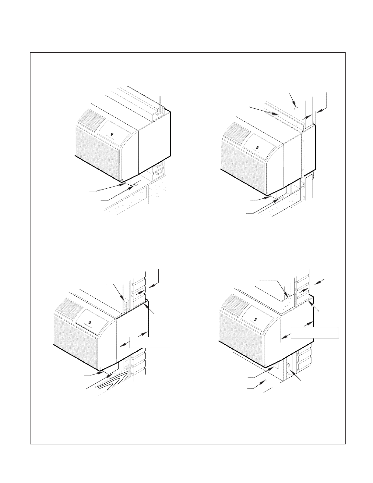
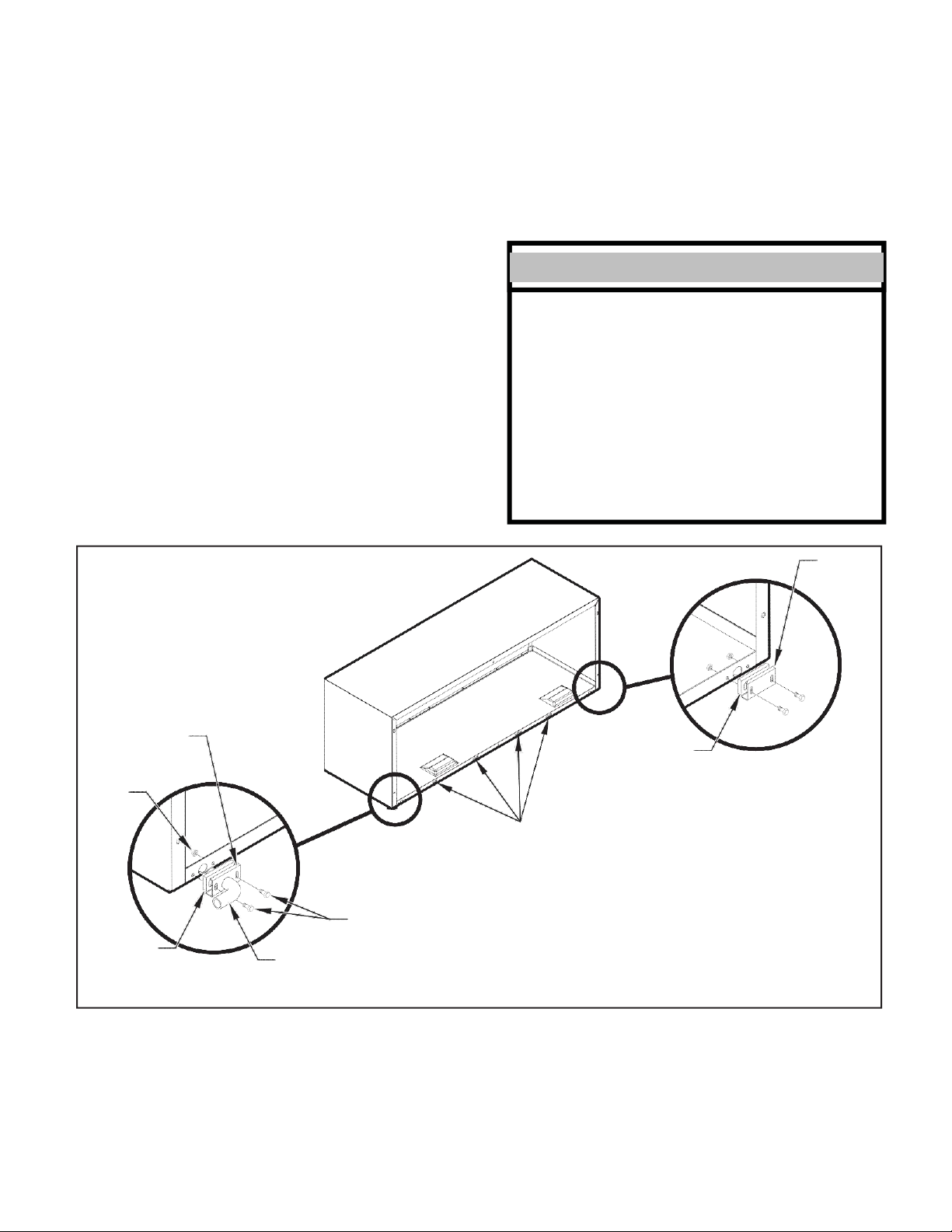
Page 18

Chassis Installation
1. Lift unit level and slide unit into wall sleeve until seal rests
firmly against front of wall sleeve.
Figure 22
3. Place tabs over top rail. (1)Push inward at bottom until panel
snaps into place(2).
4.
CAUTION
Excessive Weight Hazard
Use two or more people when installing
your air conditioner.
Failure to do so can result in back
or other injury.
SUPPLY
CORD
2. Locate the four supplied chassis mounting screws.Insert the
screws through the chassis mounting flange holes that are
aligned with the speed nuts in the wall sleeve.Tighten all four
screws(two per side).
Copper refrigerant tubes are NOT handles.
Do NOT use tubing to lift or move chassis.
To remove the front cover,pull the bottom end forward and lift it up to
clear the L bracket across the top of the chassis.
5. Plug the cord(if applicable)into the appropriate receptacle.
Restore power to the unit.
SecuringUnit
Reinstall front panel.See Figure 23.
NOTICE
POWER
FRP022
Figure 23
Replacing FrontPanel
1
2
FRP023
18
Page 19

19
Friedrich PTAC Digital Control and Unit Features
The new Friedrich digital PTAC has state of the art features to improve guest comfort, indoor air quality and conserve energy. Through the use of specifically
designed control software for the PTAC industry Friedrich has accomplished what other Manufacturer’s have only attempted – a quiet, dependable, affordable
and easy to use PTAC. Below is a list of features and their benifit to the owner.
ONLY TWO MODELS
BETTER
DEHUMIDIIFICATION
SOFT START
OPERATION
ERV 8 OUTDOOR AIR
M
FILTER
DC INVERTER
REMOTE THERMOSTAT
OPERATION
INTERNAL DIAGNOSTIC
PROGRAM
ELECTRONIC
TEMPERATURE
LIMITING
ROOM FREEZE
PROTECTION
CONDENSATE REMOVAL
SYSTEM
FreshAire PTACs utilize a DC inverter rotary compressor to ensure part load efficiencies and reliable
operation.
Some applications require the use of a wall-mounted thermostat. All new Friedrich PTACs may be
switched from unit control to remote thermostat control easily without the need to order a special model
or accessory kit.
The Friedrich digital PTAC features a self- diagnostic program that can alert maintenance to component
failures or operating problems. The internal diagnostic program saves properties valuable time when
diagnosing running problems.
By limiting the operating range, the property can save energy by eliminating “max cool” or “max heat” situ-
ations common with older uncontrolled systems. The new electronic control allows owners to set operat-
ing ranges for both heating and cooling independently of one another.
When the PTAC senses that the indoor room temperature has fallen to 50°F, the unit will cycle on the
fan (high) and the electric strip heat to raise the room temperature to 55°F, and then cycle off again. This
feature works regardless of the mode selected and can be turned off.
Condenser fan utilizes slinger ring technology to pick up condensate from the base pan and disperse it on
to the condenser coil where it evaporates. This helps to cool the coil and increase the energy efciency
of the unit.
UNIVERSAL ELECTRIC
HEATER
FACTORY RUN-TEST
Unit has a univ
All units are factory run tested to ensure trouble free operation.
ersal power cord with 20 Amp coming standard out of the box.
Page 20

DIGITAL DEFROST
THERMOSTAT
The PV-Series uses a digital thermostat to accurately monitor the outdoor coil conditions to allow the heat
pump to run whenever conditions are correct. Running the PTAC in heat pump mode saves energy and
reduces operating costs. The digital thermostat allows maximization of heat pump run time.
INSTANT HEAT
HEAT PUMP MODE
SEPAR ATE HE AT/COOL
FAN CYCLE
CONTROL
EMERGENCY
HEAT OVERRIDE
CENTRAL DESK
CONTROL
READY(ONLY FOR UNIT
CONTROL)
INDOOR COIL
FROST SENSOR
ULTRAQUIE T
AIR SYSTEM
Heat pump models will automatically run the electric heater to quickly bring the room up to temperature
when initially energized, then return to heat pump mode. This ensures that the room is brought up to
temperature quickly without the usual delay associated with heat pump units.
The owner may choose between fan cycling or fan continuous mode based on property preference. Fan
continuous mode is used to keep constant airflow circulation in the room during all times the unit is ‘ON’. Fan
cycle will conserve energy by only operating the fan while the compressor or electric heater is operating.
ability to set the fan cycling condition independently between heating and cooling mode will increase
user comfort by allowing the choice of only constantly circulating air in the summer or winter time (unlike
other PTAC brands that only allow one selection).
In the event of a compressor failure in heat pump mode, the compressor may be locked out to provide
heat through the resistance heater. This feature ensures that even in the unlikely event of a compressor
failure, the room temperature can be maintained until the compressor can be serviced.
All Friedrich digital PTACs have low voltage terminals ready to connect a central desk control energy
management system. Controlling the unit from a remote location like the front desk can reduce energy
usage and requires no additional accessories on the PTAC unit.
The frost sensor protects the compressor from damage in the event that airflow is reduced or low outdoor
temperatures cause the indoor coil to freeze. When the indoor coil reaches 33°F, the compressor is
disabled and the fan continues
the compressor returns to operation.
The PV-Series units feature an indoor fan system design that reduces soun
airow or preventing proper air circulation.
to operate based on demand. Once the coil temperature returns to 53°F,
d levels without lowering
The
HIGH EFFICIENCY
DUAL MOTOR
ROTARY COMPRESSOR
TOP-MOUNTED
ANTIMICROBIAL
AIR FILTERS
FILTERED FRESH
AIR INTAKE
ALUMINIUM ENDPLATES
R-410A REFRIGERANT
BREAK-PROOF
CONTROL DOOR
The Friedrich PTAC has been engineered so that all functional systems are optimized so that they work
together to deliver the highest possible performance.
The dual-motor design means that the indoor motor can run at slower speeds which reduces sound
levels indoors.
High efciency rotary compressors are used on all Friedrich PTACs to maximize durability and efci ency.
All Friedrich PTAC return air filters feature an antimicrobial element that has proven to prevent mold and
bacterial growth in laboratory testing. PXFTB replacement filter kits feature the same antimicrobial agent.
All filters are washable, reusable and easily accessed from the top of the unit without the removal of the
front cover.
Friedrich PTAC units are capable of introducing up to 40 CFM of outside air into the conditioned space.
The outdoor air passes through a washable mesh screen to prevent debris from entering the airstream.
Outdoor coil endplates made from aluminium reduce corrosion on the outdoor
other coil designs.
Friedrich PTAC units use environmentally-friendly refrigerant.
Break-proof control door design maintains the integrity of the unit.
coil common with
GALVANIZED ZINC
WALL SLEEVE AND
BASE PAN
Galvanized zinc coated steel wall sleeve and steel base pan undergo an 11-step preparation
process,
are powder coated with a polyester finish and cured in an oven for exceptional durability.
20
Page 21

21
System Configuration
Fresh Air Vent Control
To operate the FreshAire module please see Dip switch #3. With dip
switch in the "on" position FreshAire module will be on continuously.
With dip switch in the "OFF" position FreshAire module will be not be
activated.
Adjusting Air
Toadjustairdirection:
1.
Removefrontpanel.SeeFigure21.
2. Remove louverscrewsthat holdlouverinsertinplace(from back side of
frontpanel).SeeFigure 29.
3. Turnlouver insertand rotate180°.SeeFigure 30.
4. Replacelouverinsert.
5.
Replacescrews andfrontpanel.
Figure 26
Backside of Front Panel
LOUVER SCREWS
FRP025
FRP026
AIR DISCHARGE OUTWARD (Default)
AIR DISCHARGE UPWARD
Figure 25
Air Vent Control
POWER-DRIVEN VENT DOOR
Figure 27
Adjusting Louvers
FRP027
Page 22
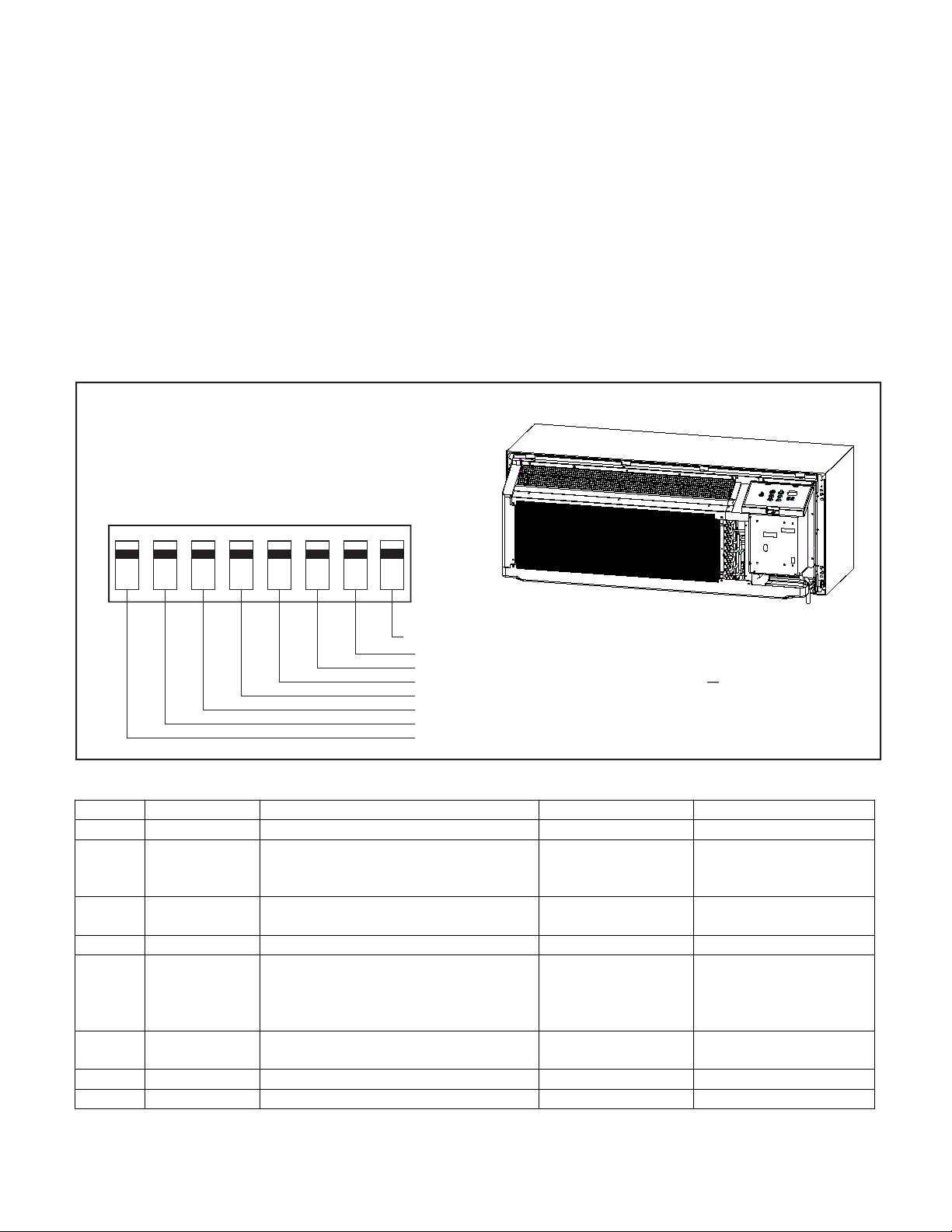
22
8
Digital Control User Input Configuration
Switch 1-Reserved.
Switch 2-Heat pump enable/disable.
Moving Dip Switch #2 to “OFF” can be set as Emergency Heat
Override. In the unlikely event of a compressor failure, a heat pump unit
may be switched to operate in only the electric heat mode until repairs
can be made.
Switch 3-Electric strip enable/disable.
Switch 4-Reserved.
Switch 5-Room Freeze Protection
Units are shipped from the factory
1 2 3 4 5 6 7
ON
OFF
LOCATION OF
DIP SWITCHES
ON UNIT
FRP028
The adjustable control dip switches are located at the front portion of the digital Smart Center. The inputs are only visible and accessible with the front cover
removed from the PTAC.
Dip SwitchSetting
With the room freeze protection enable.Room Freeze Protection can be
switched off at the owner’s preference by moving Dip Switch 5 to
“OFF”.This feature will monitor the indoor room conditions and in the event
that the room falls below 50°F, the unit will automatically run “heating”.
This occurs regardless of mode.
Switch 6-Electric memory enable/disable
The factory setting is enabled. The smart center will remember user’s
setting. After power cut recovery, the unit will operate the same status as
before power cut. Moving Dip Switch 6 to “OFF”will disable this feature,
smart center will no more remember settings.
Switch 7,Switch 8-Reserved.
Figure 28
Dip Switches
DIP SWITCH
Reserved
Reserved
Electric memory enable/disable
Room freeze protection
Reserved
Electric strip enable/disable
Heat pump enable/disable
Reserved
Switch Description Function Factory setting Option
#1 Reserved / OFF /
#2 Heat pump ON-enable heat pump;
OFF-disable heat pump, run electric heat
only.
#3 Electric strip ON-enable electric heat;
OFF-disable electric heat.
#4 Reserved / OFF /
#5 Room
Protection
#6 Electric memory
enable/disable
#7 Reserved / OFF /
#8 Reserved / OFF /
Freeze
ON-Allows the unit to ensure the indoor room
temperature does not fall below 50℉even
when turned off;
OFF-disable freeze protection.
ON-enable;
OFF-disable.
HP models-ON
Electric heat only-OFF
ON
ON OFF
ON OFF
OFF-Overrides compressor
operation(HP models only)
Factory set. Do not change.
Page 23

23
FreshAire
System
Engagement
Method
Mode
Description
SW3-1
ON / OFF
Fresh-Air Fan runs only when Dip Switch is set to ‘ON’
Fresh-Air Fan NEVER RUNS when Dip Switch is set to
‘OFF’
SW3-2
Cycle /
Continuous
2
FreshAire System
SW3 DIP SWITCH
ON/CON.
1
OFF/CYC.
SW3-2
SW3-1
Fresh-Air Fan runs continuously when SW3-1 is set to
'ON' & SW3-2 is set to 'ON'
Fresh-Air Fan cycles On/Off with the Unit Indoor Fan
when SW3-1 is set to 'ON' & SW3-2 is set to 'OFF'
Page 24

24
Digital Control Operation
Cooling Mode
Emergency Heat Operation
FRP0 29
Heating Mode
After turn on the unit, press the “Heat” button will put the unit into heating
mode.
Heat Pump Models (PVH)
When the “Heat” button is pressed initially the unit may call for electric
strips to bring the room to the set point. When the room temperature falls
2℉below the set point, the unit will turn on the compressor or electric
strip. The fan will run with compressor or electric strips. When the outdoor
ambient temperature falls below 32°F or outdoor coil temperature drops to
5℉, the unit will operate the electric strip instead of heat pump. During
heat pump mode, CPU detects the outdoor coil gets freeze, unit will go to
defrost. During the defrost operation (10min at most), there will be no
heating provide. After finishing defrost, electric heating will come on to
warm the room quickly.
In the event of a compressor failure in heat pump mode, the compressor
may be locked out to provide heat through the electric strip heater
automatically. This feature ensures that even in the unlikely event of a
compressor failure, the room temperature can be maintained until the
compressor can be serviced. If the unit still can’t run electric heater stably,
switch Dip switch 2 to OFF, it controls the emergency heat setting.
Constant Fan
Pressing the “Constant Fan” button will provide constant or cycle fan
operation in cooling or heating modes. The fan speed selection is
made by pressing either “High” or “Low” fan speed button.
Figure 29
Digital Control Panel
Pressing the “Cool” button after turn the unit on will put the unit into
cooling mode. Press “UP” or “DOWN” button to adjust the set point, the
unit will start the compressor and run appropriate frequency to maintain a
comfortable room temperature. The compressor will come on anytime that
the room temperature is 2℉above the set point. The fan will come on with
compressor.
Page 25

25
Settings- Detailed Configurations
This section is about how to set the unit operating parameter, include display temperature unit, Fahrenheit or Celsius, control master, temperature
limit, temperature calibration, display set point or room temperature.
Under OFF mode, hold [Cool] and [Low] two keys at the same time continuously for 5 seconds. This time displays ‘d0’, indicates that system
has entered the senior operation status.
Menu NO.
Function
Parameter value
Explanation
d0
Unit of temperature
F
Fahrenheit(default)
C
Celsius
d1
Control master
P
By control panel(default)
r
By 24V universal remote thermostat
rE
By 12V smart wired controller
d2
Max temperature setting
d3 to 90℉
The Min value is d2 (default 90℉)
d3
Min temperature setting
60℉ to d2
The Max value is d3 (default 90℉)
d4
Indoor
temperature
calibration
-9℃ to 9℃
If unit of temperature is changed, calibration should
be done again. If use the default value, it can be
ignored. (default 0℃/0℉)
-9℉ to 9℉
d5
Temperature
display
selection
0 or 1
0-displays room temperature
1-displays setpoint(default)
[Cool] key is used to switch parameter code and parameter value;
[UP] or [DOWN] keys are used to switch parameter code or set parameter value; [Power] key is used to save
and exit settings.
One example:
Setting target:d0(C),d1(r), d2(88℉),d3(58℉),d4(-1℉),d5(1).
Step1: hold [Cool] and [Low] two keys at the same time continuously for 5 seconds. Display:'d0'
Step2: short press [Cool] key. Display: 'F'(setting d0 has finished)
Step3: short press [Cool] key. Display:'d0'
Step4: short press [UP] key. Display:'d1'
Step5: short press [Cool] key. Display: 'P'
Step6: short press [UP] or [DOWN] key. Display: 'r' (setting d1 has finished)
Step7: short press [Cool] key. Display:'d1'
Step8: short press [UP] key. Display:'d2'
Step9: short press [Cool] key. Display:'90'
Step10: short press [DOWN] key twice. Display:'88' (setting d2 has finished)
Step11: short press [Cool] key. Display:'d2'
Step12: short press [UP] key. Display:'d3'
Step13: short press [Cool] key. Display:'60'
Step14: short press [UP] key twice. Display:'58' (setting d3 has finished)
Step15: short press [Cool] key. Display:'d3'
Step16: short press [UP] key. Display:'d4'
Step17: short press [Cool] key. Display:'0' (setting d4 has finished)
Step18: short press [Power] key to exit.
Page 26

26
Remote Control Thermostat Installation
Install Thermostat
1. Approximately 5 ft from the floor.
2. Close to or in a frequently used room,preferably on an inside wall.
3. On a section of wall without pipes or ductwork.
The Thermostat should NOT be mounted:
1. Close to a window, on an outside wall, or next to a door leading
outside.
2. Where it canbe exposed to directsunlight orheat, suchas the sun,
a lamp,fireplace or any other temperature radiating object which
may cause a false reading.
3. Close to or in the direct airflow of supply registers and/or return
air grilles.
4. Any areas with poor air circulation, such as a corner,behind a
door,or an alcove.
Remote Thermostat and
Low Voltage Control
Connections
RemoteThermostat
All Friedrich PV model PTAC units are factory configured to be controlled
by either the chassis mounted Smart Center or a 24V remote wall mounted
thermostat.The thermostat may be auto or manual changeover as long as
the control configuration matches that of the PTAC unit.
NOTE: All PV models require a single stage cool, dual stage heat
thermostat with an B reversing valve control.The Friedrich RT6
thermostat can be configured for either model.
To control the unit with a wall mounted thermostat
follow the steps below:
1. Unplug the unit before doing any work
2. Remove the low voltage terminal block from the unit.
3. Connect the corresponding terminals from the wall thermostat to
the terminal block
4. Plug the terminal block on the unitk.
5. Restore power to the unit.
6.
GL = Call for Low Fan
GH = Call for High Fan
C = Common Ground
*If only one G terminal is present on thermostat connect to GL for low
speed fan or to GH for high speed fan operation.
Under OFF mode, set menu NO.'d1' to “r”, details refer to the
previous section "Settings- Detailed Configurations" on page 25.
7. The unit is now controlled by the wall thermostat only.
If the accessory escutcheon kit (PDXRTA) is to be used, install
8.
it over the existing control panel.
NOTE:The unit control panel no longer controls the unit. To restore the control
panel, set menu NO.'d1' back to "P", details refer to the previous section "Settings-
Detailed Configurations" on page 2 .
ThermostatConnections
R = 24V Power from Unit
Y = Call for Cooling
W = Call for Heating
B = Reversing Valve Energized in Heating Mode
Figure 30
Control board with optional PDXRTB escutcheon kit
installed
FRP0 30
Page 27

27
Front Desk Control Terminal
WARNING
Electrical Shock Hazard
Turn off electrical power before service
or installation.
ALL electrical connections and wiring
MUST be installed by a qualified
electrician and conform to the National
Code and all local codes which have
jurisdiction.
Improper connection of the thermostat
control wiring and/or tampering with the
units internal wiring may result in property
damage, personal injury or death.
(ONLY FOR UNIT CONTROL)
The Friedrich PV model PTAC has built-in provisions for connection to an
external switch to control power to the unit. The switch can be a central
desk control system.
For front desk control operation, connect one side of the normal open
switch to the R terminal and the other to the FD terminal.
The control logic as below:
(a). Turn ON unit: short R and FD then release for one time within 5s.
(b). Turn OFF unit: short R and FD then release for twice within 5s.
(c). Force unit shut down for one time: short R and FD short over 5s.
NOTE: After forced shut down, you can turn on the unit again by control
panel.
NOTE: The desk control system and switches must be field supplied.
Energy Management
Sometimes known as Front Desk Control, an input is provided so that the
unit can be manually disabled from a remote location. If the unit detects
24Vac on this input, it will automatically turn itself off.If no voltage is
detected on the input , the unit will run normally.
NOTE: It is the installer's responsibility to ensure that all control wiring
connections are made in accordance withthe installation
instructions.Improper connection of the thermostat control
wiringand/or tampering with the unit's internal wiring can
void the equipment warranty.Other manufacturer's PTACs
and even older Friedrich models may have different control
wire connections.Questions concerning proper connections
to the unit should be directed to Friedrich.
Page 28

28
Final Inspection & Start-up Checklist
Inspect and ensure that all components and accessories have been
installed properly and that they have not been damaged during the
installation process.
Check the condensate water drain(s) to ensure they are adequate for
the removal of condensate water, and that they meet the approval of
the end user.
Ensure that all installations concerning clearances around the unit
have been adhered to.Check to ensure that the unit air filter, indoor
coil, and outdoor coil are free from any obstructions.
Ensure that the entire installation is in compliance with all applicable
national and local codes and ordinances that have jurisdiction.
Secure components andaccessories, such asthe chassis, decorative
front cover and control door.
Start the unit and check for proper operation of all components in
each mode of operation.Instruct the owner or operator of this units
operation,andthe manufacturer’srecommended routine maintenance
schedule.
NOTE: A log for recording the dates of maintenance and/or service
is recommended.
Present the owner or operator of the equipment with the Installation
& Operation manual, all accessory installation instructions, and the
name, address and telephone number of the Authorized Friedrich
Warranty Ser vice Company in the area for future reference if
necessary.
WARNING
Electrical Shock Hazard
Unplug Unit or turn off electrical power
to unit prior to performing maintenance
procedures
Failure to do so can result in electrical
shock or death
Front Panel Air Filter
To ensure proper unit operation, the air filters should be cleaned at least
monthly, and more frequently if conditions warrant.The unit must be
turned off before the filters are cleaned.
To remove the air filters,filter grasp the top of the filters and lift out of the
front cabinet.Reverse the procedure to reinstall the filters.
Clean the filters with a mild detergent in warm water, and allow them to
dry thoroughly before reinstalling.
Fresh Air Filter
The fresh air filter should be cleaned or replaced after 3 months of use
for maximum effectiveness The unit must be turned off before the filters
are replaced.
To replace the fresh air filters,drag the unit from wall sleeve and pull the
tape sticked to fresh air filter.
Coils & Chassis
NOTE: Do not use a caustic coil cleaning agent on coils or base pan.
Use a biodegradable cleaning agent and degreaser.The use of harsh
cleaning materials may lead to deterioration of the aluminum fins or the
coil end plates.
The indoor coil and outdoor coils and base pan should be inspected pe-
riodically (annually or semi-annually) and cleaned of all debris (lint, dirt,
leaves,paper, etc )as necessary. Under extreme conditions, more frequent
cleaning may by required.Clean the coils and base pan with a soft brush
and compressed air or vacuum.A pressure washer may also be used,
however, you must be careful not to bend the aluminium fin pack.Use a
sweeping up and down motion in the direction of the vertical aluminium
fin pack when pressure cleaning coils.
NOTE: It is extremely important to insure that none of the electrical
and/or electronic parts of the unit get wet. Be sure to cover all electrical
components to protect them from water or spray.
Decorative Front
The decorative front and discharge air grille may be cleaned with a mild
soap or detergent.Do NOT use solvents or hydrocarbon based cleaners
such asacetone, naphtha, gasoline, benzene, etc , toclean the decorative
front or air discharge grilles.
Use a damp (not wet) cloth when cleaning the control area to prevent
water from entering theunit, and possibly damaging theelectronic control.
Fan Motor & Compressor
The fan motor & compressor and are permanently lubricated, and require
no additional lubrication.
Wall Sleeve
Inspect theinside ofthe wall sleeveand drain system periodically (annually
or semi-annually) and clean as required.
Under extreme conditions, more frequent cleaning may be necessary.
Clean both of these areas with an antibacterial and antifungal cleaner.
Rinse both items thoroughly with water and ensure that the drain outlets
are operating correctly. Check the sealant around the sleeve and reseal
areas as needed.
Routine Maintenance
To ensure proper unit operation and life expectancy the following maintenance procedures should be performed on a regular basis.
Page 29

29
Basic Troubleshooting
Malfunction
Possible Reasons
S olution
Start Failure
power line bad, units don’t have power
supply.
Check the indicator LED on the LCID power head,
it should be lit up, if not, push the RESET button,
if still don’t have voltage, but power grid has
output, you need to change the power cord.
Power cord protection trip.
Check the power cord if somewhere is broken,
push the RESET button. If not solved, replace the
power cord.
Power cord isn’t fixed well.
Check that whether power cord is fixed well.
PCB fuse is broken.
Check if any load (in fan, out fan, reversing valve,
power transformer) is short circuit. Eliminate the
error and replace the fuse with the same type.
Bad contact between main board and
control panel.
Check the contact wires, make sure all contact
well.
Compressor delay start.
It’s normal, compressor will start after 3 minutes
Power fail protection.
When power on, because of auto-restart, unit
will delay starting in 120~240s
Unit in protection mode.
Please check the ERROR CODE
Main board or Control panel is bad.
Replace the main board or control panel
Control panel do not work
When the unit is switch to 24V remote
thermostat or 12V smart controller, the
control panel will not be functioning.
If you need to use control panel to take control,
you need to switch the control master. See the
SENIOR SETTINGS section.
Indoor fan/outdoor fan not function or run
slowly
Fan is locked by something or the power
wires are not fixed well; fan capacitor is not
fixed well; fan capacitor is out of service life.
Disconnect the power cord, check whether the
fan can run smooth by hand or other tools,
whether motor wire is fixed well. For the slow
running speed, you could change a new
capacitor.
Something may block the indoor/outdoor air
outlet.
Make sure that there is no obstacle at the
indoor/outdoor air outlet.
Make sure that the grill is suitable for the unit,
inappropriate grill will cause the compressor
being protected; make sure that the grill has
more than 70% turn over.
Set unsuitable temperature.
Set higher/lower temperature by the control board.
NOTE: temperature setting restriction will restrict
the setting temperature. See the SENIOR
SETTINGS section.
Indoor air filter is dirty.
Should clean the filter every month at least.
Room is hot/cold.
Let unit run a little longer that room temperature
will be lower/higher.
Heat leakage between indoor and outdoor.
Block the leakage place.
Indoor coil not cold/heat.
Charge the refrigerant.
Unit has noise
Some moving parts of the unit get loose
fixing or cause bad vibration.
Something in the air way.
Make sure that all moving parts are assembled
well, and nothing is in the air way.
Bad smell when heating
The dust on the E-heater is heating.
The bad smell will disappear a little later.
Not cooling/heating adequately
Page 30

30
Malfunction
Possible Reasons
Solution
Outlet temperature is not always
cooling/heating
Outlet temperature is not high enough when
heating by heat pump.
When outdoor ambient temp is low, the heat
pump will not be able to offer enough heat. Soon
after that, the E-heater will come on to heat.
Fan stops when cooling/heating.
It is normal when the CONSTANT FAN is OFF.
Youcan enable the CONSTANT FAN.
Outdoor is dripping water
Not install the drain pipe kit.
Install the drain pipe kit.
Indoor is dripping water
Wall sleeve is not installed correctly.
Install the wall sleeve according to the
installation manual.
Indoor coil freeze
Outdoor temperature is too low in cooling
mode.
Filter is dirty.
Clean the filter to recover the normal air flow
Error code and solutions
ERROR CODE
Meaning
Solutions
E1
Communication failure between indoor
unit and outdoor unit
Check the communication cables; make sure they are firmly connected. If
the cables are broken, replace them.
E2
Indoor Temp Sensor Open/short
Check the plug is firmly connected. If the sensor is broken, replace it.
E3
Indoor Coil Sensor Open/short
Check the plug is firmly connected. If the sensor is broken, replace it.
E4
1.
Indoor Air Outlet Sensor Open/Short
2.
Outlet Air Over Heat In Electric
Heating Mode
1.
Check the plug is firmly connected. If the sensor is broken, replace it.
2.
In E-Heating mode, check if any obstacles around the air path, remove
them. Make sure the air flow is not blocked.
E5
IPM(DC-INVERTER) Protection (Include
Heat sink Over Heat)
1.
Check the wiring of compressor to the IPM (U/V/W) terminals is
correctly connected. Wrong phase connection is not allowed.
2.
Remove obstacles in the air path that resists heat interchange.
E6
Outdoor Temp Sensor Open/Short
Check the plug is firmly connected. If the sensor is broken, replace it.
E7
Outdoor Coil Sensor Open/Short
Check the plug is firmly connected. If the sensor is broken, replace it.
EC
Compressor Fail Starting/DC-Inverter Fail
1. Check the DIP switch SW2 on the main board (3-position, in red color)
is correctly matched with the unit capacity, refer to the wiring diagram.
Make sure the compressor power cord is firmly and correctly connected.
EH
EEPROM Error
Check the EEPROM chip on the main board is firmly plugged. If still not
solve, replace the main board.
EF
Power Cord Error For 9KBTU, 30A Is
NOT Allowed
Change the power cord to 15A or 20A.
P1
Cooling/Heat Pump Over Load,
Outdoor/Indoor Coil Over Heat
Make sure indoor and outdoor unit vents are not blocked. Clear the air
filter and the condenser after a long time use.
P2
IPM Over Heat Or Over Current
Protection
1.
Make sure indoor and outdoor unit vents are not blocked.
2.
Check the DIP switch SW2 on the main board (3-position, in red color)
is correctly match with the unit capacity, refer to the wiring diagram.
3.
Make sure the compressor power cord is firmly and correctly connected.
P4
Compressor Discharge Over Heat
Protection
1.
Make sure indoor and outdoor unit vents are not blocked.
2.
Check the DIP switch SW2 on the main board (3-position, in red color)
is correctly match with the unit capacity, refer to the wiring diagram.
P7
DC Over/Under Voltage Protection
Make sure the power supply is within the requirement (AC208/230V -
10%+10%)
When outdoor temperature is drop to 55°F(12.8℃)
or below, it will cause that indoor coil freeze. Open
the fresh air door, and running at fan mode.
Page 31

31
Service & Assistance
Before calling for service, please check the "Basic Troubleshooting" section above.This may help you to find the answer to your problem, avoid
unnecessary service calls, and save you the cost of a service call if the
problem is not due to the product itself. If you have checked the "Basic
Troubleshooting" section and still need help, here is a list of available
services:
You can find the name of you local Authorized Service Provider by visiting
our web site at www.friedrich.com.
If you require further assistance you can call the Customer Support Call
Center at 1-800-541-6645.
Before calling, please make sure that you have the complete model and
serial number,and date of purchase of your equipment available. By providing us with this information we will be better able to assist you.
Our specialists are able to assist you with:
* Inspect and ensure that all components and accessories have been
installed properly and that they have not been damaged during the
installation.
* Specifications and Features of our equipment.
* Referrals to dealers, and distributors.
* Use and Care information.
* Recommended maintenance procedures.
* Installation information.
* Referrals to Authorized Service Providers and Parts depots.
Page 32

32
Accessories
New Construction Accessories
PDXWSA
PDX WSEX T18
PDXWSEXT24
PDXWSEXT
PXSE
PXGA
PXAA
PXBG
PXSC
WALL SLEEVE Galvanized zinc coated steel is prepared in an 11-
step process, then powder coated with a polyester nish and cured
in an oven for exceptional durability. The wall sleeve is insulated for
sound absorption and thermal efciency, 16" H x 42" W x 13 3/4" D.
DEEP WALL SLEEVE For walls up to 17 1/2" D.
DEEP WALL SLEEVE For walls up to 23 1/2" D.
CUSTOM DEEP WALL SLEEVE One piece extended wall sleeve for walls
from 13 1/4" to 25 1/2" D are available by special order.
Deep wall sleeve PDXWSE XT18 shown with weather panel
SLEEVE EXTENSION RETROFIT KIT Galvanized zinc coated steel, 2 3/8"
sleeve extension attached to the room side of the sleeve to allow for the
installation of a PZ-Series Friedrich PTAC in a T-Series sleeve.
GRILLE Standard, stamped aluminium, anodized to resist chalking and oxidation.
ARCHITECTURAL GRILLES C on si st of h e a v y- ga ug e 606 3 -T5 a l u minum
alloy: 42" W x 16" H x 1 1/8" D
PXAA – Clear, extruded aluminum
PXBG – Beige acrylic enamel
PXSC – Also available in custom colors.
PDXWSA
PXG
A
PXDR10
PXCJA
PDXDA A
DEA
PDX
CONDENSATE DRAIN KIT Attaches to the bottom of the wall sleeve for in-
ternal draining of condensate or to the rear wall sleeve ange for external
draining. Recommended on all units to remove excess condensate. Packaged in quantities of ten.
CONDUIT KIT WITH JUNCTION BOX Hard wir e conduit kit with junctio n b ox
for 208/230V and 265 V unit s (subbase not required). Kit includes a
means of quick disconnect for easy removal of the chassis. *Required
for 265V installations.
LATERAL DUCT ADAPTER Attaches to the Friedrich PTAC/PTHP unit to direct up to 35% of the total air ow to a second room. The unit-mounted duct
plenum features a front-mounted aluminum grille that has two positions
to provide the most optimal air direction. The air may be directed to either
the left or the right of the unit through the supplied 3
plenum. Plenum may be cut to length by the installer. Kit includes duct
plenum, front grille, 47" duct extension, duct discharge grille, duct end cap
and all necessar y mounting hardware.
1
LATERAL DUCT EXTENSION Additional 3
use with the L ATERAL DUCT ADAPTER. A maximum of 3 duct extensions total may be used. Note: Ducted airow is reduced as duct length is
increased.
/2 H" x 7" W x 47" L plenum for
1
/2 H" x 7 W" x 47" L
PXA A
Page 33

33
New Construction Accessories
PXFTB
REPLACEMENT FILTER PACK These are original equipment return air
lters. They are reusable and can be cleaned by vacuuming, washing, or
blowing out, and are sold in convenient ten-p acks. (Two lters per chassis).
PXSBA DECORATIVE SUBBASE Pr ovides unit support for wall s le ss than si x inches
thick. Includes leveling legs, side filler panels and mounting brackets fo r el ec tr ical acces sories. Accepts circuit breake r, power disconnect
switch, or conduit kit.
PXSB ELECTRICAL SUBBASE Prov ides unit suppor t for wall s less than six inches
thick. Includes leveling legs, side ller panels, mounting brackets, a plugin receptacle and field-wiring access. The subbase also includes electrical knockouts for a power disconnect switch or circuit breaker.
PXSB23020 Electrical Subbase - 230V 15 & 20A
RT6
RT6P
PXSB23030
PXSB26515
PXSB26520
PXSB26530
DIGITAL REMOTE THERMOSTATS
RT6 Wired single stage cool, single stage heat for PDE models or single
Electrical Subbase - 230V 30A
Electrical Subbase - 265V 15A
Electrical Subbase - 265V 20A
Electrical Subbase - 265V 30A
stage cool, dual stage heat for PDH model thermostat features high/low
fan speed switch. Thermostat is hard wired and can be battery powered or
unit powered. Features backlit display and multiple congur ation modes.
For use on Friedrich PTACs and Vert-I-Paks.
RT6P Wireless single stage cool, single stage heat for PDE models or single stage cool, dual stage heat for PDH model thermostat features high/
low fan speed switch. Thermostat is hard wired and can be battery powered or unit powered. Features backlit display and multiple conguration
modes. For use on Friedrich PTACs and Ver t-I-Paks.
PFAXWC1 WIRELESS WALL-MOUNTED CONTROLLER (battery powered).
WRT1 WIRELESS DIGITAL REMOTE THERMOSTAT Single stage cool, single
stage heat for PDE models or single stage cool, dual stage heat for PDH
model thermostat features high/low fan speed switch. Thermostat is
wireless and is battery powered. Features backlit display and multiple
conguration modes. For use on Friedrich PTACs and Vert-I-Paks.
PDXRTB REMOTE THERMOSTAT ESCUTCHEON KIT This kit contains ten escutch-
eons th at can be pla ced over the factor y contr ol buttons when a remote wall
mounted thermostat is used. The escutcheon directs the guest to the wall
thermostat for oper ation and retains the LED window to disp lay error codes
and diagnostic information.
EMRT1
EMWRT1
ENERGY MANAGEMENT THERMOSTATS
EMRT1
Wired thermostat with occupancy sensor.
EMWRT1
Wireless thermostat with occupancy sensor.
EMOCT
Online connection kit.
EMRAF EMRHCF
Remote access fee. Remote humidity control fee.
Page 34

34
Friedrich Air Conditioning Co.
10001 Reunion Place, San Antonio, TX 78216
800.541.6645
PACKAGED TERMINAL AIR CONDITIONERS
LIMITED WARRANTY
We will not be responsible for and the user will pay for:
1. Service calls to:
2. Parts or labor provided by anyone other than an authorized service center.
3. Damage caused by:
1. Repair of the unit
2. A refund to the customer for the prorated value of the unit based upon the remaining warranty period of the unit.
3. Providing a replacement unit of equal value
www.friedrich.com
PV-SERIES
SAVE THIS CERTIFICATE.It gives you specific rights.You may also have other rights which may vary from state to state and province to province.
In the event that your unit needs servicing, contact your nearest authorized service center. If you do not know the nearest service center, ask the company
that installed your unit or contact us - see address and telephone number above. To obtain service and/or warranty parts replacement, you must notify an
authorized FRIEDRICH Air Conditioning Co. service center, distributor, dealer, or contractor of any defect within the applicable warranty period.
When requesting service: please have the model and serialnumber from your unit readily available.
Unless otherwise herein, the following applies:
FRIEDRICH PACKAGED TERMINALAIR CONDITIONERSAND HEAT PUMPS
LIMITED WARRANTY - FIRST YEAR (Twelve (12) months from the date of installation). Any part found to be defective in the material or workmanship
will be repaired or replaced free of charge by our authorized service center during the normal working hours; and
LIMITED WARRANTY - SECOND THROUGH FIFTH YEAR (Sixty (60) months from the date of installation). ON THE SEALED REFRIGERATION
SYSTEM. Any part of the sealed refrigeration system that is defective in material or workmanship will be repaired or replaced free of charge (excluding freight
charges) by our authorized service center during normal working hours. The sealed refrigeration system consists of the compressor, metering device, evaporator, condenser, reversing valve, check valve, and the interconnecting tubing.
These warranties apply only while the unit remains at the original site and only to units installed inside the continental United States, Alaska, Hawaii, Puerto Rico, Mexico and Canada. The warranty applies only if the unit is installed and operated in accordance with the printed instructions
and in compliance with applicable local installation and building codes and good trade practices. For international warranty information, contact
the Friedrich Air Conditioning Company - International Division.
Any defective part to be replaced must be made available to FRIEDRICH in exchange for the replacement part. Reasonable proof must be presented to
be new or remanufactured. Replacement parts and labor are only warranted for any unused portion of the unit’s warranty.
A)Instruct on unit operation. B)Replace house fuses or correct house wiring. C)Clean or replace air filters. D)Remove the unit from its
installed location when not accessible for service required. E) Correct improper installations.
A)Accident,abuse,negligence,misuse,riot,fire,flood,or acts of God. B)operating the unit where is a corrosive atmosphere containing
chlorine,fluorine,or any damaging chemicals(other than in a normal residential environment). C)Unauthorized alteration or repair of the
unit,which in turn affects its stability or performance. D) Failing to provide proper maintenance and service. E) Using an incorrect power
source. F) Faulty installation or application of the unit.
We shall not be liable for any incidental, consequential, or special damages or expenses in connection with any use or failure of this unit. We
have not made and do not make any representation or warranty fitness for a particular use or purpose and there is no implied condition of fitness for a particular use or purpose. We make no expressed warranties except as stated in this certificate. No one is authorized to change this
certificate or to create for us any other obligation or liability in connection with this unit. Any implied warranties shall last for one year after
the
original purchase date. Some states and provinces do not allow limitations on how long an implied warranty or condition lasts, so the above
limitations or exclusions may not apply to you.The provisions of this warranty are in addition to and not a modification of or subtraction from the
statutory warranties and other rights and other rights and remedies provided by law.
Performance of Friedrich’s Warranty obligation is limited to one of the following methods:
The method of fullfillment of the warranty obligation is at the sole discretion of Friedrich Air Conditioning.
In case of any questions regarding the provisions of this warranty, the English version will govern.
 Loading...