

Page 1
WallMaster®ProductProfile
PackagedTerminalAirConditionersandHeatPumps
7,000 / 9,000 / 12,000 / 15,000 Btu/h
TheAll-newWallMaste_
isaperfectfitfor:
Newconstructioninhotels/motels,
medicalfacilities,assistedlivingcenters,
apartments/c0nd0s,officesuites,
dormitoriesandremodels.
TheNewWallMaster®retrofitsinto
existing16"x42"sleevesmoreeasilythan
othermanufacturers'PTACs.
StandardFeatures
• Ultrahigh efficiency- up to 12.2 EER.
• Unique component mounting and isolation
provide ultraquiet operation and vibration
dampening.
• Large well-spaced control panel with universal
markings and non-removable controls
• Attractive front coverandtamper resistant
contoured discharge grille blend with any decor.
• Quiet and efficient rotary compressor mounted
on vibration isolators, with internal high
temperature overload protection.
• Built-in damper allows up to 70 CFM of fresh air.
• Convenient top-mounted return air filters feature
an anti-microbial treatmentfor protection against
fungal and bacterial growth.
• Availablein heat pumpor electric heat.
• Front coverfastens tochassis with
thumbscrews hidden from user.
• Emergency heat compressor override switchon
all heat pumps.
• Single,totally enclosed "clam shell" motor
design protects against premature failure.
• Optional seacoast protection for harshcoastal
environments.
• Complete line of accessories.
• Remotethermostat control units areavailable.
• Units are rated in accordance
with ARI Standard 310/380.
• Manufactured intheU.S.A.
PTAC-BW-04 (1-04)
Page 2
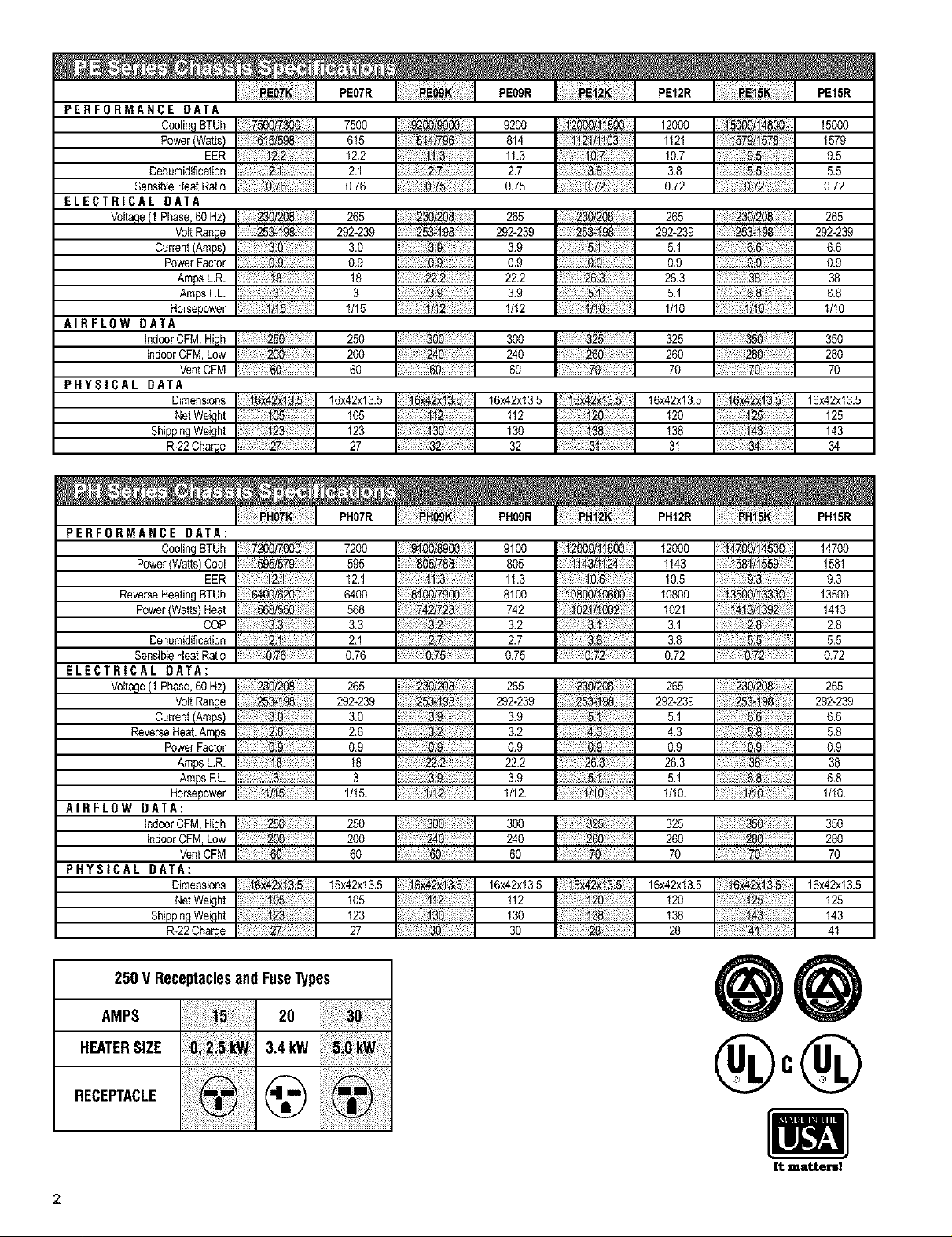
PERFORMANCE DATA
CoolingBTUh
Power/Watts)
Dehumidification
SensibieHeatRatio
ELECTRICAL DATA
Voltage(1 Phase,60Hz)
VoltRange
Current(Arnps)
PowerFactor
AmpsL,R.
AmpsRL
Horsepower
AIRFLOW DATA
IndoorCFM,High
IndoorCFM,Low
VentCFM
PHYSICAL DATA
Dimensions
NetWeight
ShippingWeight
R-22Charge
PERFORMANCE DATA:
CoolingBTUh
Power(Watts)Cool
ReverseHeatingBTUh
Power(Watts)Heat
Dehumidification
SensibleHeatRatio
ELECTRICAL DATA:
Voltage(1 Phase,60Hz)
VoltRange
Current(Amps)
ReverseHeat.Amps
PowerFactor
ArnpsL,R.
ArnpsRL
Horsepower
AIRFLOW DATA:
IndoorCFM,High
IndoorCFM,Low
VentCFM
PHYSICAL DATA:
Dimensions
NetWeight
ShippingWeight
R-22Charge
EER
EER
COP
7200/7000
95,'579
2,i
6400/6200
568/550
3.3
2.1
0.76
230/208
253-198
.g
1/15,
PE07R
75O0
615
12,2
2,1
0.76
265
292-239
3,0
0,9
18
1/15
250
200
60
16x42x13.5
9200/9000
8!4/796
2.7
&75
253-198
3_
0,9
22-2
3
_6x42xt3.5
105
123
27
PH07R PH09R PHI2R PH15R
7200
595
12.1
64OO
568
3,3
2,1
0,76
265
292*239
3,0
2,6
0,9
18
1/15.
25O
200
6O
16x42x13,5
105
123
27
130
32
g1OOlSgO0
895/78_
i.3
8t00/7900
742/72
32
2.7
,75
230/20
253198
3,9
32
0.9
222
3
;12.
PE09R
9200
814
11.3
2.7
0.75
265
292-239
3,9
0,9
22.2
3,9
1112
300
240
60
16x42x13,5
112
130
32
9100
805
11,3
8100
742
32
2.7
0.75
265
292-239
3,9
32
0,9
22.2
3,9
1/12.
300
240
60
16x42x13,5
112
130
3O
30/208
253-198
0.9
26,3
5./
/J!0
12®0/11800
_4311!24
0.5
0800/t060_
3:1
.8
.72
230/208
253.198
5.!
43
O.9
26`3
5_
/I_
PE12R
12OOO
1121
10.7
3,8
0,72
265
292*239
5,1
0,9
26.3
5,1
1/10
325
26O
7O
16x42x13,5
120
138
31
12000
1143
10.5
10800
1021
3.1
3.8
0.72
265
292-239
5.1
4.3
0.9
26.3
5.1
1/10,
325
260
70
16x42x13.5
120
138
28
18000/i4800
57911578
9.5
55
#.72
230/208
253.f_
6.8
_.9
38
_ii! _
; _50
8x42x13.5
_25
i43
_4700/14500
581/!559
9`3
13500/13300
_413t1392
2.8
.72
230/208
8.
5.8
0.9
38
6.8
16x42x1&5
125
43
41
292-239
16x42x13.5
292-239
16x42x13.5
PEI5R
15000
1579
9.5
5.5
0.72
265
6.6
0.9
38
6.8
1/10
350
280
7O
125
143
34
147OO
1581
9,3
13500
1413
2,8
5,5
0.72
265
6,6
5,8
0,9
38
6,8
1/10.
350
28O
7O
125
143
41
250 V ReceptaclesandFuseTypes
AMPS 20
HEATERSIZE 3.4kW
RECEPTACLE @
2
®°®
i
It =tteml
Page 3
PE07
PEO9
PE12
PEI5
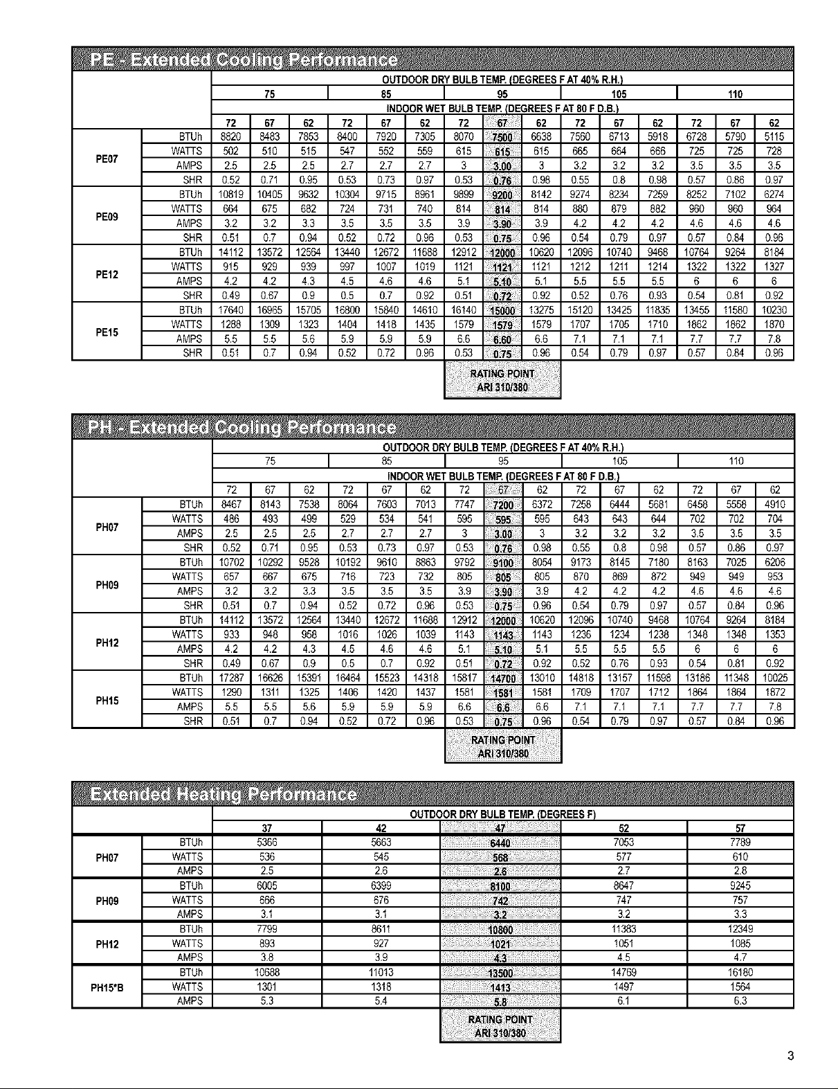
OUTDOORDRYBULB TEMR(DEGREESF AT40%R.H.}
75 I 85 I 95 I 105 I 110
INDOORWET BULBTEMP.(DEGREESFAT80F D.B.)
72 67 62 72 67 62 72 62 72 67 62 72 67 62
BTUh 8820 8483 7853 8400 7920 7305 8070 7500 6638 7560 6713 5918 6728 5790 5115
WATTS 502 510 515 547 552 559 615 615 665 664 666 725 725 728
AMPS 2.5 2.5 2,5 2.7 2.7 2,7 3 3 3,2 3,2 3.2 3.5 3,5 3,5
SHR 0.52 0,71 0,95 0.53 0.73 0,97 0,53 0,98 0,55 0,8 0.98 0,57 0,86 0.97
BTUh 10819 10405 9632 10304 9715 8961 9899 9200 8142 9274 8234 7259 8252 7102 6274
WATTS 664 675 682 724 731 740 814 814 880 879 882 960 960 964
AMPS 3.2 3.2 3,3 3.5 3.5 3,5 3,9 3.9 4,2 4,2 4.2 4.6 4,6 4,6
SHR 0.51 0.7 0,94 0.52 0.72 0,96 0,53 0,96 0,54 0.79 0.97 0,57 0,84 0.96
BTUh 14112 13572 12564 13440 12672 11688 12912 2000 10620 12096 10740 9468 10764 9284 8184
WATTS 915 929 939 997 1007 1019 1121 _21 1121 1212 1211 1214 1322 1322 1327
AMPS 4.2 4.2 4,3 4.5 4.6 4,6 5,1 5.1 5,5 5,5 5.5 6 6 6
SHR 0.49 0,67 0,9 0.5 0.7 0,92 0,51 0,92 0,52 0.76 0.93 0,54 0,81 0.92
BTUh 17640 16965 15705 16800 15840 14610 16140 1580_ 13275 15120 13425 11835 13455 11580 10230
WATTS 1288 1309 1323 1404 1418 1435 1579 1579 1707 1705 1710 1862 1862 1870
AMPS 5.5 5.5 5.6 5.9 5.9 5,9 6,6 6.6 7.1 7.1 7.1 7.7 7,7 7,8
SHR 0.51 0.7 0,94 0.52 0.72 0,96 0,53 0,96 0,54 0.79 0.97 0,57 0,84 0.96
75
72 67 62 62 72 67 62
BTUh 8467 8143 7538 5681 6458 5558 4910
PHO7
PHO9
PHI2 4.2 4.2 4,3 4,5 4.6 4.6 5,1 5,1 5.5 5.5 5,5 6
PHI5
PHO7
PHO9
PHI2
PHI5*B
WATTS 486 493 499 844 702 702 704
AMPS 2.5 2.5 2,5 3,2 3,5 3.5 3.5
SHR 0.52 0,71 0,95 0,98 0,57 0.86 0.97
BTUh 10702 10292 9528 7180 8163 7025 6206
WATTS 657 667 675 872 949 949 953
AMPS 3.2 3.2 3,3 4,2 4,6 4.6 4.6
SHR 0.51 0.7 0,94 0,97 0,57 0.84 0.96
BTUh 9284 8184
14112 13572 12584 13440 12672 11688 12912 10620 12096 10740 9468 10784
WATTS 1348 1353
AMPS 6 6
BTUh
WATTS
AMPS
BTUh
WATTS
AMPS
BTUh
WATTS
AMPS
BTUh
WATTS
AMPS
BTUh
WATTS
AMPS
933 948 958 1016 1026 1039 1143 1143 1236 1234 1238 1348
SHR 0.81 0.92
0.49 0,67 0,9 0,5 0.7 0.92 0,51 0.92 0.52 0,76 0,93 0,54
17287 16626 15391 16484 15523 14318 15817 13010 14818 13157 11598 13186 11348 10025
1290 1311 1325 1406 1420 1437 1581 1581 1709 1707 1712 1864 1884 1872
5.5 5.5 5,6 5,9 5.9 5.9 6,6 6,6 7.1 7.1 7,1 7,7 7.7 7.8
SHR
0.51 0.7 0,94 0.52 0.72 0.96 0,53 0.96 0.54 0,79 0,97 0,57 0.84 0.96
37
5366
536
2.5
6005
666
3,1
7799
893
3,8
10688
1301
53
I 85 I 98 I 105 I 110
8084 7603 7013 7747 6372 7258 8444
529 534 541 595 595 843 843
0.53 0.73 0.97 0,53 0.98 0.55 0.8
10192 9610 8863 9792 8054 9173 8145
716 723 732 805 805 870 869
0.52 0.72 0.96 0,53 0.96 0.54 0,79
OUTDOORDRYBULBTEMP.(DEGREESF AT40%R.H.)
72 67 62 72 62 72 87
2,7 2.7 2.7 3 3 3.2 3.2
3,5 3.5 3.5 3,9 3,9 4.2 4.2
INDOORWET BULBTEMP.(DEGREESFAT 80 F D.B.}
OUTDOORDRYBULBTEMP.(DEGREESF)
42
5663
545
2.6
6399
676
3,1
8611
927
3,9
11013
1318
5,4
2._
08o0
47
844o
88
3.2
o21
_35oo
141
5.8
7053
8847
11383
1051
14769
1497
52
577
2.7
747
3.2
4.5
6.1
57
7789
610
2,8
9245
757
3,3
12349
1085
4,7
16180
1584
6,3
Page 4
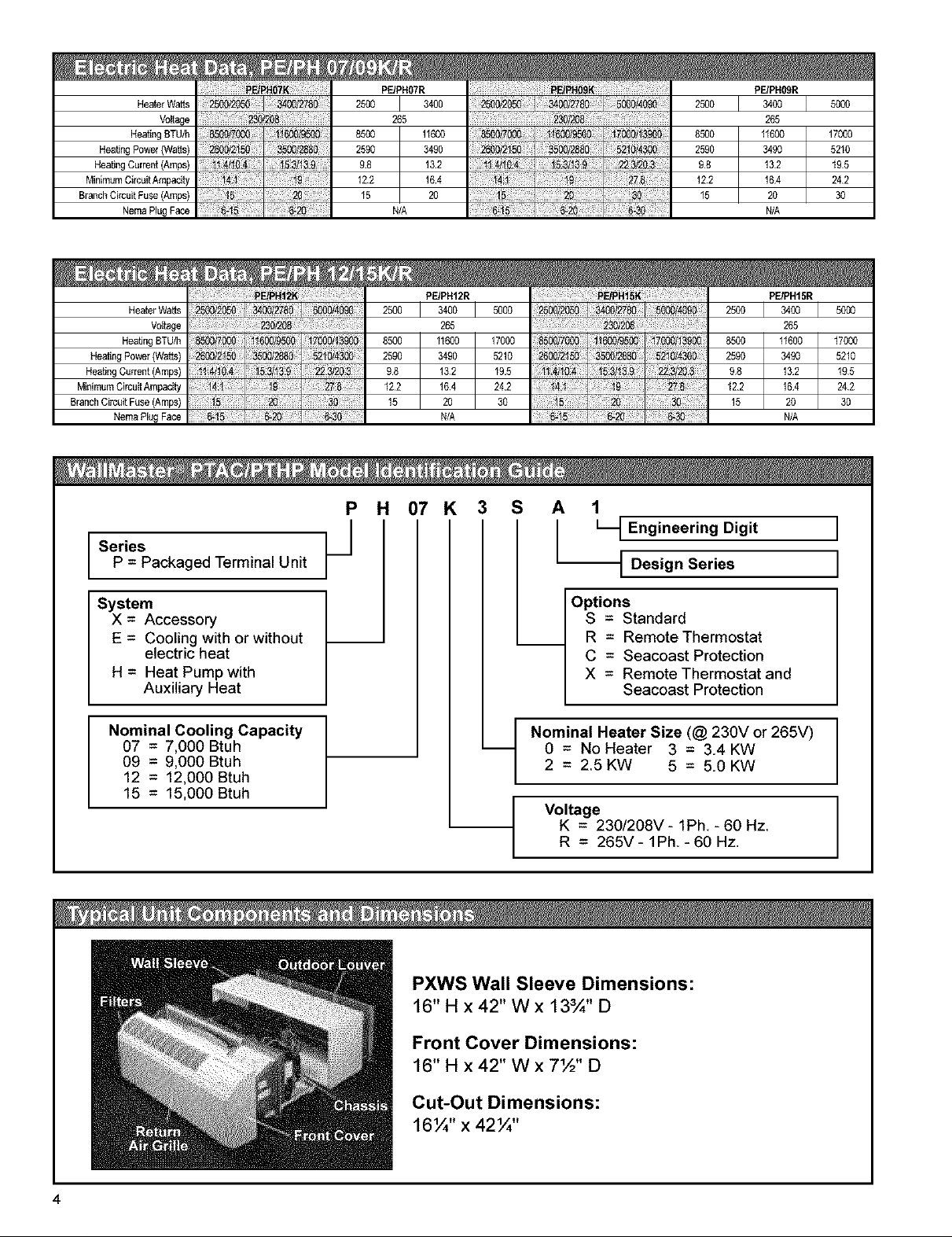
HeaterWatts
Voltage
HeatingBTU_
HeatJn0 Power(Watts)
HeatingCurrent (Amps)
MinimumCircuttAmpac_ty
BranchCircuitFuse (Amps)
NemaPlugFace
HeaterWatts
Vottage
Heating 8TU/h
Heating Powe_(Watts)
HeWn0 Current (Amps)
MinimumCircuitArnpactty
BranchCircuitFuse(Amps)
NemaPlugFace
PE/PBO7R
2500 J 3400
265
8500 11600
98 132
122 164
15
N/A
PE/PB09R
2500 l
2500
N/A N/A
3400 5000
265
11600 17000
3490 5210
132 195
164 242
20 30
N/A
Series
P = Packaged Terminal Unit
System
X = Accessory
E = Cooling with or without
electric heat
H = Heat Pump with
Auxiliary Heat
Nominal Cooling Capacity
07 = 7,000 Btuh
09 = 9,000 Btuh
12 = 12,000 Btuh
15 = 15,000 Btuh
P H 07 K
/
3 S
A
I_t Engineering Digit
t Design Series
Options
S = Standard
R = Remote Thermostat
C = Seacoast Protection
X = Remote Thermostat and
Seacoast Protection
Nominal Heater Size (@ 230V or 265V)
0 = No Heater 3 = 3.4KW
2 = 2.5KW 5 = 5.0KW
Voltage
K = 230/208V-1Ph,-60Hz,
R = 265V-1Ph.-60Hz.
]
I
PXWS Wall Sleeve Dimensions:
16"H x42" Wx 13¾" D
Front Cover Dimensions:
16" H x 42" W x 7½" D
Cut-Out Dimensions:
16¼" x 42¼"
4
Page 5

Lintel Used To Support
Masonry Walls
Electrical
Receptacle
Electrical
Receptacle
Insulation
No holes are permitted in the top or bottom of
the sleeve. (Exception: PXDRI0 Drain Kit)
Wall Sleeve Extension,
42" x 16" Frame, 20 gauge
minimum, painted or
aluminum
J
Smooth side of clip on Room side
Note the use of a lintel under the first course
of bricks above the wall sleeve. Do not use the
wall sleeve as a lintel. The mounting screw
holes shown are to be made by the installer.
Wall Sleeve
Outside
Width of Wall Four
Condensate
Notches
; corners
IMPORTANT NOTE: The
113 ! silicone bead MUST
U_ _ extend3 uptheside
_ _ Sealant inside (4 bottom
/ of the two flanges to
_/ prevent condensate from
leaking.
Page 6

When using an external drain system, the
condensate is removed through either of two
drain holes on the back of the wall sleeve.
Select the drain hole which best meets your
drainage situation and install the drain kit. Seal
off the other with a cover plate.
Place the drain tube through the gasket and
the mounting plate with the flange toward the
wall sleeve.
Primary Area:
Condensation from the
chassis collects in the
sleeve in this area. The
Primary Area is the
preferred installation
location.
PXDR10 DRAIN KIT
Foam Gasket
Attach the drain tube assembly toone of the two
drain holes at the rear of the wall sleeve. The
large flange on the mounting plate is positioned
at the bottom of the sleeve facing toward the
sleeve. When the drain tube is positioned at the
desired angle, tighten the screws.
CAUTION:
Bodily injury can be caused by louvers
falling from a building during installation.
It is recommended that a safety line be
attached to the louver and an anchor point
inside the building during installation.
Back
of wall
sleeve
1/2" O.D. Tube
Plate
Installation
1. Screw a threaded metal stud into each
of the holes at the four corners of the
louver.
2.
From inside the building, grasp the
louver at the vertical supports and
maneuver the louver through the wall
sleeve. Pull towards you until the
threaded studs are inserted into the
four holes of the wall sleeve.
3. While holding the louver with one hand,
start washers and nuts on each of the
four studs. Tighten the nuts securely.
6
Page 7

Allunitsshallbefactoryassembled,piped,wiredandfully
chargedwithR-22.Allunitsshallbecertifiedinaccordance
withARIStandard310forairconditionersandARIStandard
380forheatpumps.UnitsshallbeULlistedandcarryaUL
label.Allunitsshallbefactoryrun-testedtocheckoperation
andbeFrieddchWallMaster®orequivalent.
Thebasicunitshallnotexceed16"highx42"wideOverall
depthoftheunitfromtherearoftheFriedrichwallsleeve
tothefrontofthedecorativefrontcovershallnotexceed
21¼".Theunitshallbedesignedsothatroomintrusion
maybeaslittleas7¾".Installationsinwallsdeeperthan
131/4"maybeaccomplishedwiththeuseofawallsleeve
extension(PXWE).Unitshalldrawinambientairthrough
bothsidesof anoutdoorarchitecturallouveror grille
measuring42"widex 16"highandshallexhaustheated
airoutthemiddleportionofthelouver.Thearchitectural
louverandwallsleeveshallbedesignedsothatthelouver
maybeinstalledfromtheinsideofthebuilding.
REFRIGERATION SYSTEM - The refrigeration system
shall consist of a hermetically sealed rotary compressor
that is externally mounted on vibration isolators no smaller
than 1 ¾" dia. X 1½" high; condenser and evaporator coils
constructed of copper tubes and aluminum plate fins; and
capillaries as expansion devices. Unit shall have a fan
slinger ring to increase efficiency and condensate disposal
and have a drain pan capable of retaining 1½ gallons of
condensate. Atertiary condensate removal system shall
also be incorporated for back up and shall overflow through
the wall sleeve and to the outside of the building as a
safeguard against damage to the interior room.
AIR HANDLING SECTION - The evaporator and condenser
fans shall be driven by a single, totally enclosed, ball
bearing, permanently lubricated split capacitor, "clam-shell"
style fan motor, Airflow shall be directed intothe room by a
single, injectionmolded, high-impact polystyrene discharge
grille. The grill shall have openings no larger than 3/8"
high x 3" wide to prevent personal injury or damage to the
PTAC unit, and will be reversible to allow air to be directed
upward or outward as determined by the installer,
The chassis shall have a built-in damper capable of
providing at least 60 CFM of fresh air intothe conditioned
area. Afine mesh screen shall filter the incomingfresh air,
There must be a provision for locking the damper closed
to ensure a proper seal.
CONTROLS - Covered controls shall be accessible in a
compartment at least 9" wide with the controls no deeper
than 1¼" in the opening to facilitate easy operation of the
unit. Controls shall include dual rotary knobs for setting
of the thermostat and for mode control. The knobs will be
tamper proof to prohibit the removal of knobs by the user
and shall feature a temperature-limiting device adjustable
by the owner, The control panel shall be clearly marked
and easy to read. Universal symbols shall be used with
markings no smaller than 12-point type. The chassis may
be ordered with the option of remote thermostat control.
Other controls accessible without removal of the chassis
shall include fan cycle switch, fresh air vent control and
emergency heat override switch (heat pump only).
GENERAL CONSTRUCTION - The wall sleeve shall be
constructed of 18 gauge G90 zinc-ceated steel It shallbe
prepared by a processwhere itiszinc phosphatepretreated
and sealed with a chromate rinse, then powder coated for
maximum coverage and protection The sleeve shall be
shipped with a protective weatherboard and a structural
center support, and be insulated for thermal efficiency. The
grille or louvershall be shipped separately and made from
stamped orextruded anodized aluminum All louvers shall
be in the horizontal plane
The front panel shall lock to the chassis by means of two
factory-supplied thumbscrews to prevent tampering. The
front panel will feature a contoured discharge with no sharp
corners. The air filters shall be reusable and be accessible
without removal of the front cover. The filters will have
an antimicrobial treatment to protect against fungal and
bacterial growth.
All 265V units shall possess an integral, over-current time-
delay protective device.
The unit shall have a plasticfan, fan shroud and drain pan
for corrosion protection and to help prevent rust on the side
of the building below the outdoor louver.
A complete line of accessories shall be available
from Friedrich to equip the PTAC for a multitude of
applications.
Friedrich Installation/Start-Up Specialists shall be available
to answer questions regarding proper installation practices
and in some cases for on-site start-up inspections.
Page 8

Friedrich PTAC Accessories
MODEL NUMBER DESCRIPTION PHOTO
WALL SLEEVE G-90 zinc coated steel isprepared in an
PXWS
eleven-step process, then powder coated for maximum
coverage and protection. The wall sleeve is insulated for
sound absorption and thermal efficiency. 16" High x42"
Wide x 13¾" Deep.
PXWS
PXGA
PXAA
PXDB
PXSC
PXDRIO
PXWE
GRILLE Standard, stamped aluminum, anodized to resist
chalking and oxidation.
ARCHITECTURAL GRILLES Consist of heavy-gauge
6063-15 aluminum alloy:
PXAA- Clear, extruded aluminum
PXDB- Dark bronze acrylic enamel
PXSC- Also available in custom colors.
CONDENSATE DRAIN KIT Attaches to the bottom
of the wall sleeve for internal draining of condensate
or to the rear wall sleeve flange for external draining.
Recommended on all units to remove excess condensate.
Packaged in quantities of ten.
DEEP WALL SLEEVE EXTENSION A four inch deep
anodized aluminum extension that attachesto the outside
of the wall sleeve when the wall is greater than 13¼" thick
(11¾" when a subbase is used, 12¼" when a lateral duct
is used).
PXDB
PXDRIO
PXWE
DECORATIVE SUBBASE Provides unit support for
walls less than six inches thick. Includes leveling legs,
PXSB
side filler panels and mounting brackets for electrical
accessories. Accepts circuit breaker, power disconnect
switch and conduit kit.
CONDUIT KIT WITH JUNCTION BOX Hard wire conduit
kit with junction box for 208/230V and 256V units
PXCJ
(subbase not required). Kit includes a means of quick
disconnect for easy removal of the chassis. *Required
for 265V installations.
PXCJ
DESK CONTROL KIT A field installed kit which allows
PXDC
the unit to be turned on or off from a remote central
station via a 24V interface. This kit is compatable with
all chassis models.
PXDC ;_
8
Page 9

MODEL NUMBER DESCRIPTION PHOTO
DIGITAL REMOTE THERMOSTAT Digital electronic
RT2
thermostat with "one touch" adjustment. Mounts to wall
for control of unit.
RT2
MODEL NUMBER DESCRIPTION PHOTO
SLEEVE EXTENSION RETROFIT KIT G-90 zinc coated
PXSE
steel, 2¼" sleeve extension attached to the room side
of the sleeve to allow for the installation of a P-Series
Friedrich PTAC ina T-Series sleeve.
PXSE
LATERAL DUCT ADAPTER Attaches to the PTAC/
PTHP unit and provides a transition to direct up to 35%
PXDA
of the total CFM to a secondary room, either left or right
of the unit. Kit includesduct plenum with discharge grille
and internal baffle, adapter and end cap.
LATERAL DUCT EXTENSION A three foot insulated
plenum that attaches to the left or right side of the duct
PXDE
adapter. The extension can be cut to length by the
installer, Maximum allowable straight extension is 15
feet.
CONTROL DOOR LOCK KIT Locks control door to
PXDL
prevent tampering by unauthorized users
REPLACEMENT FILTER PACK Original equipment
return air filters which feature an antimicrobial treatment
PXFT
to protect against fungal and bacterial growth. They are
reusable and can be cleaned by vacuuming, washing or
blowing out. Sold in convenient ten-packs. (Two filters
per chassis).
ITEM DESCRIPTION
STANDARD UNIT Standard PTAC/PCHP chassis Can be 230/208V or 265V, electric or heat
S pump.
PXDA
PXFT
R the unit.
REMOTE THERMOSTAT Chassis option necessary for wall mounted thermostat control of
SEACOAST PROTECTION Additional protection for PTAC/PTHP units ina coastal or corrosive
C environment. The entire outdoor coil is submerged in a specially formulated enamel coating,
then oven-cured for a tough, corrosion-resistant finish.
9
Page 10

Friedrich Air Conditioning Company
P.O. Box 1540
San Antonio, TX 78295
(210) 357-4400
WALLMASTER ®P-SERIES
PACKAGED TERMINAL AIR CONDITIONERS
LIMITED WARRANTY
SAVE THIS CERTIFICATE. It gives you specific rights, you may also have other rights which may vary from state to stste and
province to province.
In the event that your unit needs servicing, contact your nearest authodzed service center. If you do not know the nearest service
center, ask the company that installed your unit or contact us - see address and telephone number above. When requesting
service: please have the model and serial number from your unit readily available.
Unless specified otherwise herein, the following applies: PACKAGED TERMINAL AIR CONDITIONERS AND HEAT PUMPS
LIMITED WARRANTY - FIRST YEAR (Eighteen (t8) Months from the original data of purchase or twelve (12) months
from instellafion). Any defect in the unit'smatedal or workmanship will be repaired or replaced free ofcharge by our authorized
service center during the normal working hours; and
LIMITED WARRANTY - SECOND THROUGH FIFTH YEAR (Sixty-six (66) months from the data of purchase) ON THE
SEALED REFRIGERATION SYSTEM. Any part of the sealed refrigeration system on the P-series that is defective in material or
workmanship will be repaired or replaced free of charge (excluding freight charges) by our authorized service center during
normal working hours. The sealed refrigeration system consists of the compressor, metering device, evaporator, condenser,
reversing valve, check valve, and the interconnecting tubing.
These warranties apply only while the unit remains at the original site and only to units installed inside the continental
United States, Alaska, Hawaii, Puerto Rico and Canada. The warranty applies only if the unit is installed and operated
in accordance with the printed instructions and in compliance with applicable local installation and building cedes and
good trade practices. For international warranty information, contact the Frledrich Air Conditioning Company -
International Division.
Reasonable proof must he presented to establish the original purchase date, otherwise the beginning date of this certificate will
be considered to be our shipment date plus sixty days. Replacement parts can he new or remanufactured. Replacement parts
and labor are only warranted for any unused portion of the unit's warranty.
We will not be responsible for and the user will pay for:
1. Service calls to:
A) Instruct on unit operation. B) Replace house fuses or correct house widng. C) Clean or replace air filters.
D) Remove the unit from inaccessible locations. E) Correct improper installations.
2. Parts or labor provided by anyone other than an authorized service center.
3. Damage caused by:
A) Accident, abuse, negligence, misuse, riot, tire, fioed, or acts of God. B) Operating the unit where there is a
corrosive atmosphere containing chlorine, fluorine, or any damaging chemicals (other than in a normal
residential environment). C) Unauthodzed alteration or repair of the unit, which in turn affects its stability or
performance. D) Failing to provide proper maintenance and service. E) Using other than a "Seacoast
Protected" unit in a coastal environment. F) Using an incorrect power source. G) Faulty installation or
application of the unit.
We shall not be liable for any incidental, consequential, or special damages or expenses in connection with any use or
failure of this unit. We have not made and do not make any representation or warranty of fitness for a particular use or
purpose and there is no implied condition of fitness for a particular use or purpose. We make no expressed warranties
except as stated in this certificate. No one is authorized to change this certificate or to create for us any other
obligation or liability in connection with this unit. Any implied warranties shall last for one year after the original
purchase date. Some states and provinces do not allow limitations on how long an implied warranty or condition lasts, so the
above limitations or exclusions may not apply to you. The provisions of this warranty are in addition to and not a modification of
or subtraction from the statutory warranties and other rights and remedies provided by law.
10
In case of any questions regarding the provisions of this warranty, the English version will govern.
(12103)
Page 11

WALLMASTER ® P-SERIES
PACKAGED TERMINAL AIR CONDITIONERS
Purchaser:
Project:
Engineer:
Submitted By:
ITEM PLAN DESIGNATION
ACCESSORIES
PXWS Wall Sleeve
PXWE Deep Wall Extension
PXGA Standard Outdoor Louver
PXAA Architectural Louver, clear
PXDB Architectural Louver, dark bronze
PXSC Architectural Louver, color matched
PXDL Control Door Lock Kit
RT2 Digital Wall Mounted Thermostat
QUANTITY
P.O, # / Date:
Location:
Architect:
ForApproval: 1 For Reference:
COOLING BTU/H VOLTAGE FRIEDRICH MODEL
Qty
Qty
Qty
Qty
Qty
Qty
Qty
Qty
PXDR1O Condensate Drain Kit (pkg/10) Qty
PXS8 Subbase Qty
PXDS Power Disconnect Switch Qty
PXCJ Conduit Kit w/Junction Box Qty
PXSE T-Sedes Sleeve Adapter Qty
PXDA Lateral Duct Adapter Qty
PXDE Lateral Duct Extension Qty
PXDC Desk Control Relay Qty
NOTES:
FEATURES
• Ultraquiet operation
• Super high energy efficiency, up to 12.2 EER
• Anti-microbial treated filters
• Easy to use controls feature tamper-proof knobs
• Built-in fresh air damper provides up to 70 CFM
• Two cooling and heating speeds plus fan-only setting
• Front cover fastens to chassis easily with thumbscrews hidden from user
• Thermostat limlter switch
• Emergency heat switch (heat pump models)
• Easy access, easy-to-clean filter
• Made in the U,S,A,
• UL Listed and ARt Certified
DIMENSIONS
Wall Sleeve Overall Depth
Width _ Depth Sleeve with Front
42" 16" 13_/_" 21!4''
Wall Opening - 421A'' wide x 161A'' high
11
Page 12

IMultiplesolutionso
Onetrustedname.
PostOffice8ox 15401SanAntonio,Texas78295-1540
4200N.PanAmExpresswayI SanAntonio,Texas78218-5212
(210)357-4400•FAX(210)357-44801www.friedrich,com PTAC-BW-O4 (1-04)
Friedrich Air Conditioning Co.
 Loading...