

Page 1

Service Manual
WallMaster® P SERIES
Packaged Terminal Air Conditioners
Packaged Terminal Heat Pumps
· Standard Unit
· Seacoast Protected Unit
· Remote Thermostat Unit
P2K23-DM (4-03)
Page 2

3
Table of Contents
Typical Unit Components .......................................... 4
Introduction................................................................ 4
Unit Identication....................................................... 5
Unit Specications..................................................... 6
PE Series Air Conditioner–Cooling Performance...... 6
PH Series Heat Pump–Heating/Cooling Performance..... 6
PE / Ph Series Electric Heating Data ........................ 6
Sequence Of Operation............................................. 7
Electrical Supply........................................................ 8
Supply Circuit ............................................................ 8
Electrical Rating Tables ............................................. 8
Standard Unit Operation............................................ 9
Temperature Limiting Thermostat.............................. 9
Standard Unit Control Panel...................................... 9
Remote Thermostat Unit Installation ....................... 10
Manual Changeover Thermostat............................. 10
Remote Thermostat Unit Operation..........................11
Room Thermostats...................................................11
Location....................................................................11
Heat Anticipators ..................................................... 12
Calculating Approximate CFM................................. 12
Fan Cycle Switch..................................................... 13
Hot Start Sensor...................................................... 13
Refrigerant Charging ............................................... 13
Method Of Charging ................................................ 13
Undercharged Refrigerant Systems ........................ 14
Overcharged Refrigerant Systems .......................... 15
Restricted Refrigerant Systems............................... 18
Capillary Tube Systems........................................... 17
Reversing Valve Operation ...................................... 17
Electrical Circuit And Coil ........................................ 18
Checking Reversing Valve....................................... 18
Touch Test In Heating/Cooling Cycle....................... 18
Procedure For Changing Reversing Valve .............. 18
Compressor Checks................................................ 19
Locked Rotor Voltage (L.R.V.) Test ......................... 19
Single Phase Connections ...................................... 19
Determine L.R.V. ..................................................... 19
Amperage (L.R.A.) Test ........................................... 19
Single Phase Running And L.R.A. Test ................... 19
External Overload.................................................... 19
Checking The External Overload............................. 19
Single Phase Resistance Test ................................. 20
Compressor Replacement....................................... 20
Capacitors ............................................................... 21
Capacitor Check ..................................................... 21
Capacitor Connections ............................................ 21
System Switch Continuity Check............................ 22
Thermostat Continuity Check .................................. 22
Fan Cycle Switch Continuity Check ........................ 23
Fan Speed Switch Continuity Check ....................... 23
Emergency Heat Switch Continuity Check.............. 24
Routine Maintenance .............................................. 25
Troubleshooting Chart — Cooling .......................... 26
Troubleshooting Chart — Heating.......................... 27
Electrical Troubleshooting Chart ............................. 28
Wiring Diagrams................................................. 29-34
2
Page 3
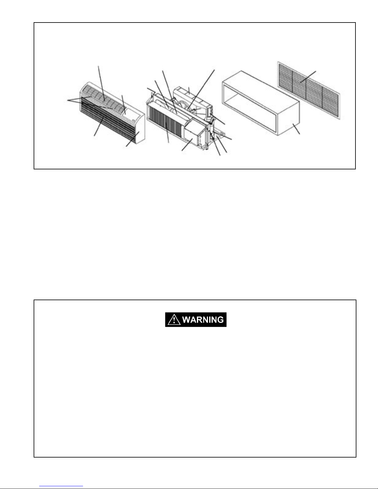
Typical Unit Components
Discharge Air Grille
Filters
Return Air Grille
Blower Wheel
Indoor Blower Housing
Gasket
Control Door
Evaporator Coil
Front Cover
Condenser
Control Panel
Condenser Fan Blade
Shroud
Gasket
Condenser
Coil
Compressor
Basepan
Outdoor Grille
Wall Sleeve
INTRODUCTION
This service manual is designed to be used in conjunction with the installation manuals provided with each air
conditioning system component.
This service manual was written to assist the professional HVAC service technician to quickly and accurately
diagnose and repair any malfunctions of this product.
This manual, therefore, will deal with all subjects in a general nature. (i.e. All text will pertain to all models).
IMPORTANT: It will be necessary for you to accurately identify the unit you are
servicing, so you can be certain of a proper diagnosis and repair. (See
Unit Identication.)
The information contained in this manual is intended for use by a qualied service technician
who is familiar with the safety procedures required in installation and repair, and who is equipped
with the proper tools and test instruments.
Installation or repairs made by unqualied persons can result in hazards subjecting the
unqualied person making such repairs to the risk of injury or electrical shock which can be
serious or even fatal not only to them, but also to persons being served by the equipment.
If you install or perform service on equipment, you must assume responsibility for any bodily
injury or property damage which may result to you or others. Friedrich Air Conditioning
Company will not be responsible for any injury or property damage arising from improper
installation, service, and/or service procedures.
3
Page 4
5
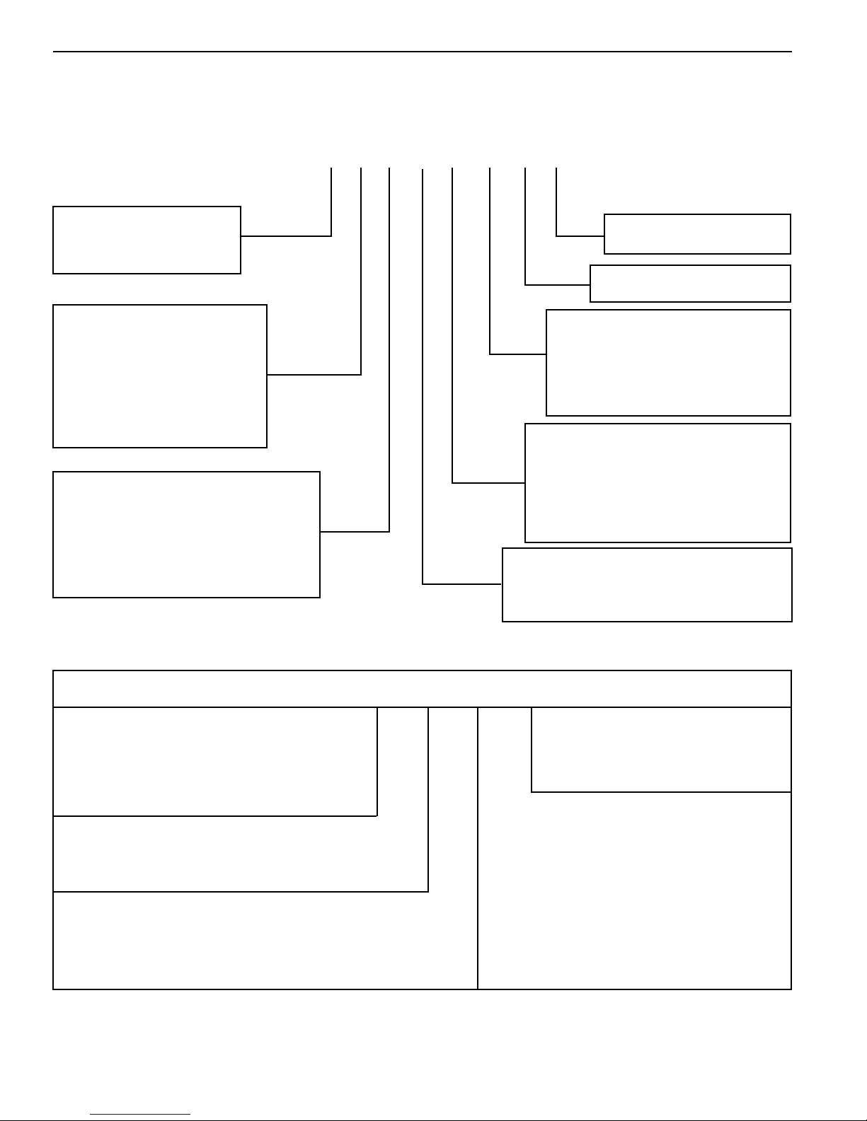
UNIT IDENTIFICATION
Model Number Code
P H 07 K 3 S B 1
Series
P = P series
System
X= Accessory
E= Cooling with or
without electric heat
H = Heat Pump with
Auxiliary Heat
Nominal Cooling Capacity
07 = 7,000 - 7,100 BTUh
09 = 9,000 - 9,100 BTUh
12 = 11,500 - 11,700 BTUh
15 = 14,100 - 14,200 BTUh
Engineering Digit
Design Series
Options
S = Standard
R = Remote Thermostat
C = Seacoast Protection
X = Seacoast Remote
Nominal Heater Size
(@ 230V or 265V)
0 = No Heater
2 = 2.5 KW
3 = 3.4 KW
5 = 5.0 KW
Voltage
K = 230/208V - 1Ph. - 60 Hz.
R = 265V - 1Ph. - 60 Hz.
PTAC Serial Number Identication Guide
Serial Number
Decade Manufactured
L=0 C=3 F=6 J=9
A=1 D=4 G=7
B=2 E=5 H=8
Year Manufactured
A=1 D=4 G=7 K=0
B=2 E=5 H=8
C=3 F=6 J=9
Month Manufactured
A=Jan D=Apr G=Jul K=Oct
B=Feb E=May H=Aug L=Nov
C=Mar F=Jun J=Sep M=Dec
4
L B L P 00000
Production Run Number
PRODUCT LINE
R=RAC
P=PTAC
E=EAC
V=VPAK
H=Split
Page 5
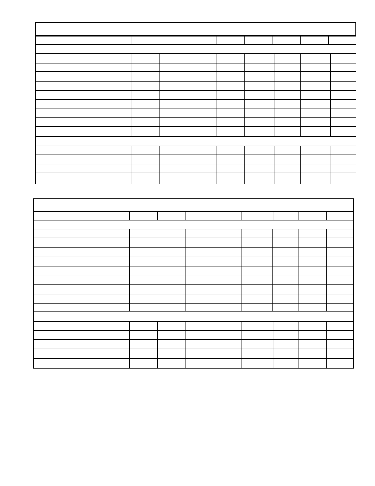
GENERAL INFORMATION – PE SERIES
Model PE07K PE07R PE09K PE09R PE12K PE12R PE15K PE15R
POWER
VOLTAGE (1 PHASE, 60 Hz) 230/208 265 230/208 265 230/208 265 230/208 265
VOLT RANGE 253-198 292-239 253-198 292-239 253-198 292-239 253-198 292-239
POWER (WATTS) 615/598 615 800/783 800 1091/1073 1091 1579/1578 1579
CURRENT (AMPS) 3 3 3.9 3.9 5.1 5.1 6.6 6.6
POWER FACTOR 0.9 0.9 0.9 0.9 0.9 0.9 0.9 0.9
AMPS L.R. 18 18 22.2 22.2 26.3 26.3 38 38
AMPS F.L. 3 3 3.9 3.9 5.1 5.1 6.8 6.8
HORSEPOWER 1/15. 1/15. 1/12. 1/12. 1/10. 1/10. 1/10. 1/10.
R-22 CHARGE (OZ) 27 27 30 30 28 28 28 28
PERFORMANCE
COOLING BTUh 7500/7300 7500 9200/9000 9200 12000/11800 12000 15000/14800 15000
INDOOR CFM 250 250 300 300 325 325 350 350
SENSIBLE HEAT RATIO 0.79 0.79 0.76 0.76 0.76 0.76 0.75 0.75
VENT CFM 60 60 60 60 70 70 70 70
GENERAL INFORMATION – PH SERIES
Model PH07K PH07R PH09K PH09R PH12K PH12R PH15K PH15R
POWER
VOLTAGE (1 PHASE, 60 Hz) 230/208 265 230/208 265 230/208 265 230/208 265
VOLT RANGE 253-198 292-239 253-198 292-239 253-198 292-239 253-198 292-239
POWER (WATTS) 590/574 590 791/774 791 1121/1023 1121 1581/1559 1559
CURRENT (AMPS) 3 3 3.9 3.9 5.1 5.1 6.6 6.6
POWER FACTOR 0.9 0.9 0.9 0.9 0.9 0.9 0.9 0.9
AMPS L.R. 18 18 22.2 22.2 26.3 26.3 38 38
AMPS F.L. 3 3 3.9 3.9 5.1 5.1 6.8 6.8
HORSEPOWER 1/15. 1/15. 1/12. 1/12. 1/10. 1/10. 1/10. 1/10.
R-22 CHARGE (OZ) 27 27 32 32 34.5 34.5 33 33
PERFORMANCE
COOLING BTUh 7200/7000 7000 9100/8900 9100 12000/11800 12000 14700/14500 14700
REVERSE HEATING BTUh 6400/6200 6400 8100/7900 8100 10800/10600 10800 13500/13300 13500
INDOOR CFM 250 250 300 300 325 325 350 350
SENSIBLE HEAT RATIO 0.79 0.79 0.76 0.76 0.76 0.76 0.75 0.75
VENT CFM 60 60 60 60 70 70 70 70
5
Page 6
7
Sequence of Operation
A good understanding of the basic operation of the refrigeration
system is essential for the service technician. Without this
understanding, accurate troubleshooting of refrigeration system
problems will be more difcult and time consuming, if not (in some
cases) entirely impossible. The refrigeration system uses four
basic principles (laws) in its operation they are as follows:
1. "Heat always ows from a warmer body to a cooler body."
2. "Heat must be added to or removed from a substance before
a change in state can occur"
3. "Flow is always from a higher pressure area to a lower
pressure area."
4. "The temperature at which a liquid or gas changes state is
dependent upon the pressure."
The refrigeration cycle begins at the compressor. Starting the
compressor creates a low pressure in the suction line which draws
refrigerant gas (vapor) into the compressor. The compressor then
"compresses" this refrigerant, raising its pressure and its (heat
intensity) temperature.
The refrigerant leaves the compressor through the discharge Line
as a hot High pressure gas (vapor). The refrigerant enters the
condenser coil where it gives up some of its heat. The condenser
fan moving air across the coil's nned surface facilitates the transfer
of heat from the refrigerant to the relatively cooler outdoor air.
When a sufcient quantity of heat has been removed from the
refrigerant gas (vapor), the refrigerant will "condense" (i.e. change
to a liquid). Once the refrigerant has been condensed (changed)
to a liquid it is cooled even further by the air that continues to ow
across the condenser coil.
The PTAC design determines at exactly what point (in the
condenser) the change of state (i.e. gas to a liquid) takes place.
In all cases, however, the refrigerant must be totally condensed
(changed) to a Liquid before leaving the condenser coil.
The refrigerant leaves the condenser Coil through the liquid line
as a warm high pressure liquid. It next will pass through the
refrigerant drier (if so equipped). It is the function of the drier to
trap any moisture present in the system, contaminants, and large
particulate matter.
The liquid refrigerant next enters the metering device. The
metering device is a capillary tube. The purpose of the metering
device is to "meter" (i.e. control or measure) the quantity of
refrigerant entering the evaporator coil.
In the case of the capillary tube this is accomplished (by design)
through size (and length) of device, and the pressure difference
present across the device.
Since the evaporator coil is under a lower pressure (due to the
suction created by the compressor) than the liquid line, the liquid
refrigerant leaves the metering device entering the evaporator coil.
As it enters the evaporator coil, the larger area and lower pressure
allows the refrigerant to expand and lower its temperature (heat
intensity). This expansion is often referred to as "boiling". Since
the unit's blower is moving indoor air across the nned surface
of the evaporator coil, the expanding refrigerant absorbs some of
that heat. This results in a lowering of the indoor air temperature,
hence the "cooling" effect.
The expansion and absorbing of heat cause the liquid refrigerant
to evaporate (i.e. change to a gas). Once the refrigerant has been
evaporated (changed to a gas), it is heated even further by the air
that continues to ow across the evaporator coil.
The particular system design determines at exactly what point (in
the evaporator) the change of state (i.e. liquid to a gas) takes place.
In all cases, however, the refrigerant must be totally evaporated
(changed) to a gas before leaving the evaporator coil.
The low pressure (suction) created by the compressor causes
the refrigerant to leave the evaporator through the suction line
as a cool low pressure vapor. The refrigerant then returns to the
compressor, where the cycle is repeated.
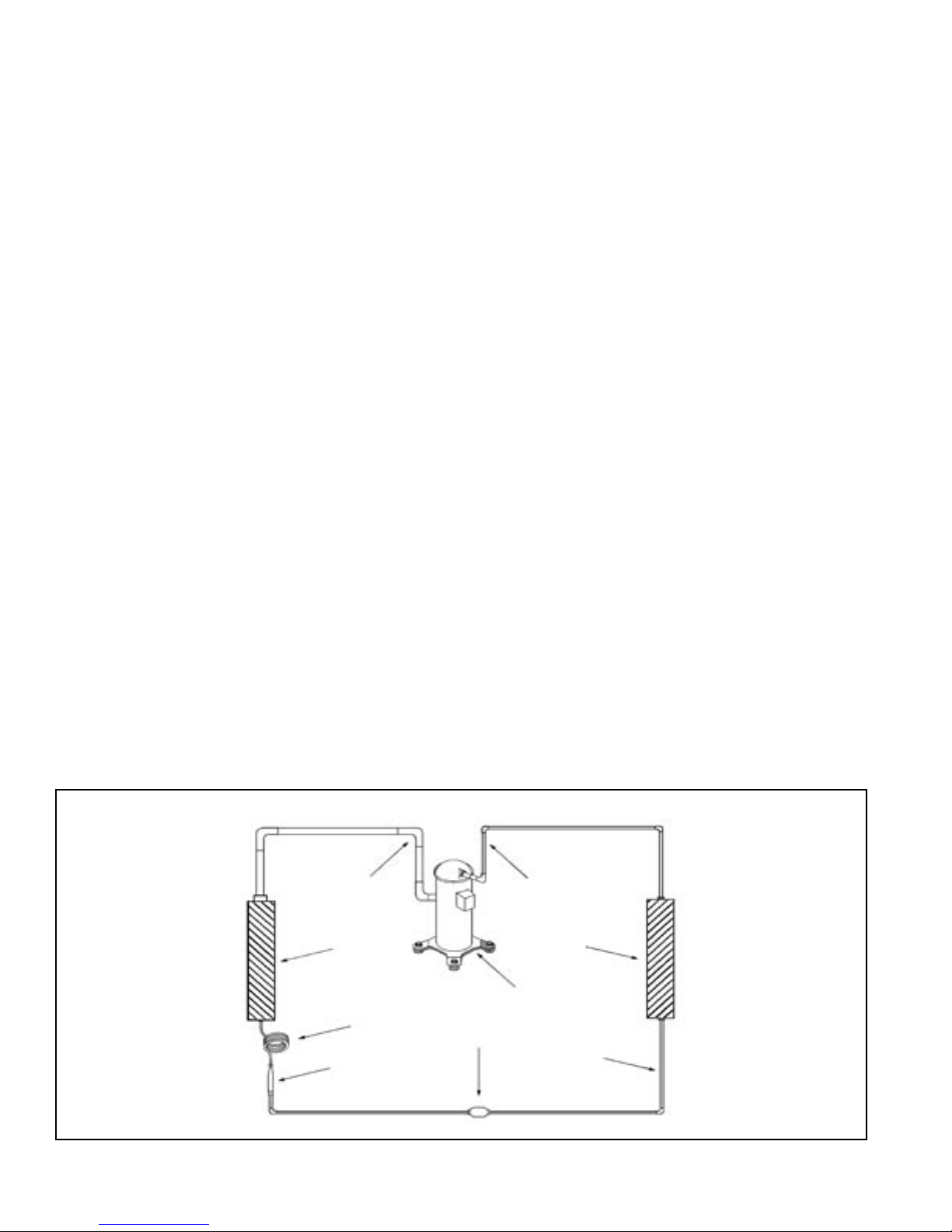
Suction
Line
6
Evaporator
Coil
Metering
Device
Refrigerant
Strainer
Discharge
Line
Compressor
Refrigerant Drier
Condenser
Coil
Liquid
Line
Page 7
Electrical Rating Tables
All 230/208 volt units are equipped with power cords.
NOTE: Use Copper Conductors ONLY
Wire sizes are per NEC, check local
codes for overseas applications
Table 1 250 V Receptacles and Fuse Types
AMPS 15 20 * 30
RECEPTACLE
MANUFACTURER PART NUMBERS
Hubbell 5661 5461 9330
P & S 5661 5871 5930
GE GE 4069-1 GE4182-1 GE4139-3
Arrow-Hart 5661 5861 5700
TIME-DELAY TYPE
FUSE 15 20 30
(or HACR circuit breaker)
HACR — Heating, Air conditioning, Refrigeration
* May be used for 15 Amp applications if fused for 15 Amp
NOTE: 265 volt units are permanently connected.
Table 2
Recommended branch circuit wire sizes
Nameplate
AWG Wire size**
maximum circuit
breaker size
15 14
20 12
30 10
AWG — American Wire Gauge
* Single circuit from main box
** Based on copper wire, single insulated
conductor at 60°C
Wire Size Use ONLY wiring size recommended for single outlet branch circuit.
Fuse/Circuit Use ONLY type and size fuse or HACR circuit breaker indicated on unit's rating plate. Proper
Breaker current protection to the unit is the responsibility of the owner.
NOTE: A time delay fuse is provided with 265V units.
Grounding Unit MUST be grounded from branch circuit through service cord to unit, or through separate ground
wire provided on permanently connected units. Be sure that branch circuit or general purpose outlet
is grounded.
Receptacle The eld supplied outlet must match plug on service cord and be within reach of service cord.
Refer to Table 1 for proper receptacle and fuse type. Do NOT alter the service cord or plug. Do
NOT use an extension cord.
Wire Sizing Use recommended wire size given in Table 2 and install a single branch circuit. All wiring must
comply with local and national codes. NOTE: Use copper conductors only.
Electric shock hazard.
Turn off electric power before service or installation.
All electrical connections and wiring MUST be installed by a qualied electrician
and conform to the National Electrical Code and all local codes which have
jurisdiction.
Failure to do so can result in property damage, personal injury and/or death.
7
Page 8
9
Standard Unit Operation
Rotary Switch Operation
Rota t e the te m p e r a t u r e dial i n small
increments in the warmer or cooler direction.
Moving the dial more than 1/4" at a time may
overcompensate and result in an extreme hot
or cold situation.
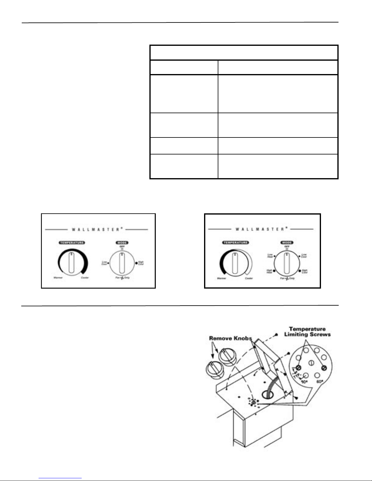
Standard Unit Control Panel
Control
Temperature
Low and High Cool
Low and High Heat
Fan Only
Operation
The full-range thermostat maintains room
temperature at the desired setting in both
the heating and cooling modes. Turn the
dial counterclockwise for warmer and
clockwise for a cooler temperature.
Operates the unit on cooling. Cooling
will not begin if the room temperature is
below 60°F.
Operates the unit on heating. Some
models do not provide this selection.
Circulates air within the room at high
fan speed only. No heating or cooling
functions are active.
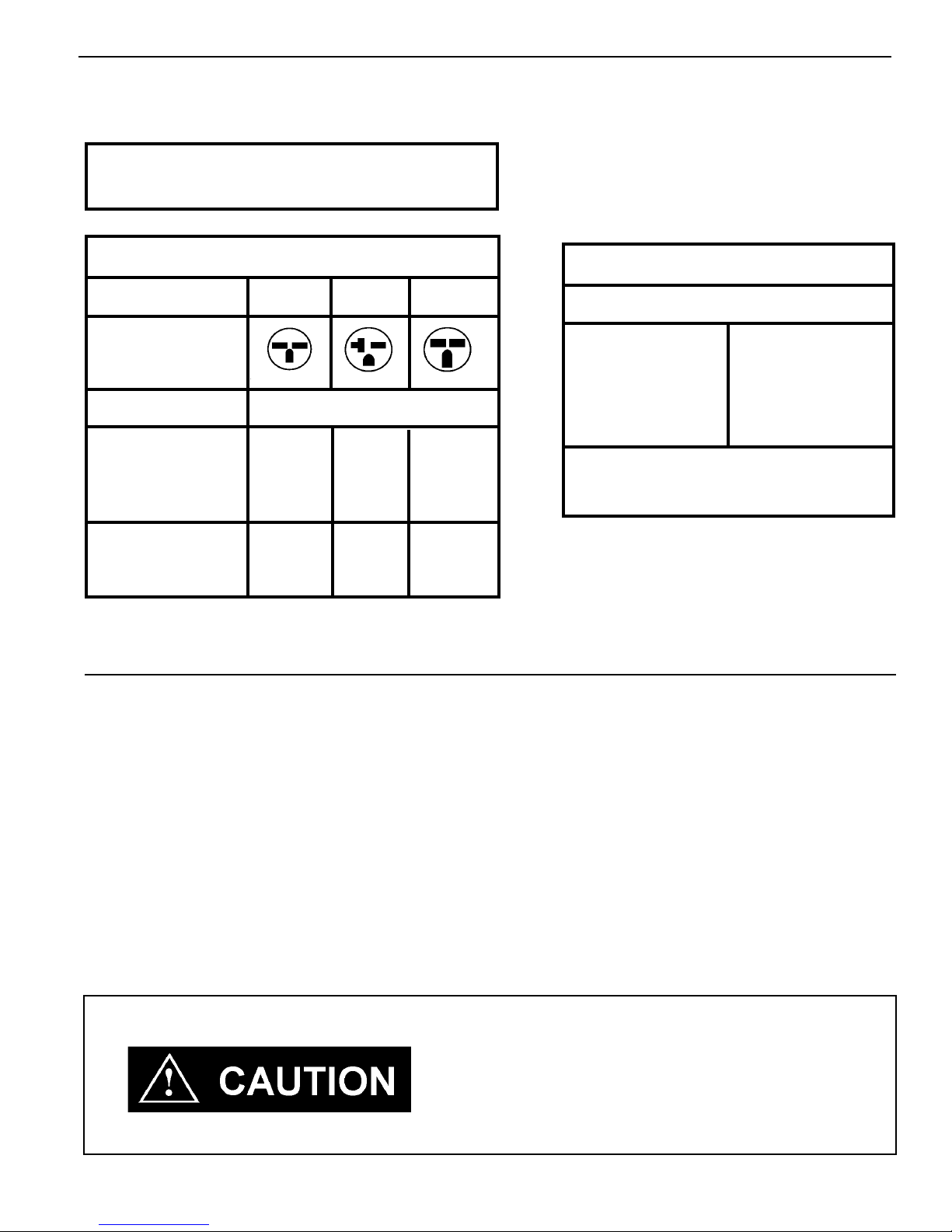
COOLING ONLY MODEL
Temperature Limiting Thermostat
1. Set the thermostat knob to center of dial.
2. Remove the four screws holding the control panel. Pull up
on the thermostat knob and remove it.
3. Locate the two temperature limiting screws. These screws
are factory installed for a maximum temperature range of 60°90°F. Each hole in the dial plate represents approximately
a 4° change from the adjacent hole.
4. To adjust the temperature range, move the temperature
limiting screws to the desired location.
5. Replace the knob when the desired range has been set.
6. Replace the control panel.
EXAMPLE: To set a maximum temperature range of
approximately 64° to 86°F, move the screws to
the locations shown in the diagram at right.
8
HEAT/COOL MODEL
Page 9
Remote Thermostat Unit Installation
1. Remote Thermostat Selection & Wiring Guidelines for Packaged
Terminal Air Conditioners
Follow the instructions and recommendations of the thermostat manufacturer for installation and wiring. Do not
use a conventional heat pump thermostat with emergency electric heat selection for our heat pump units. Our
units make an automatic decision about turning on electric heat if the heating demand cannot be met by the heat
pump due to low outdoor temperatures.
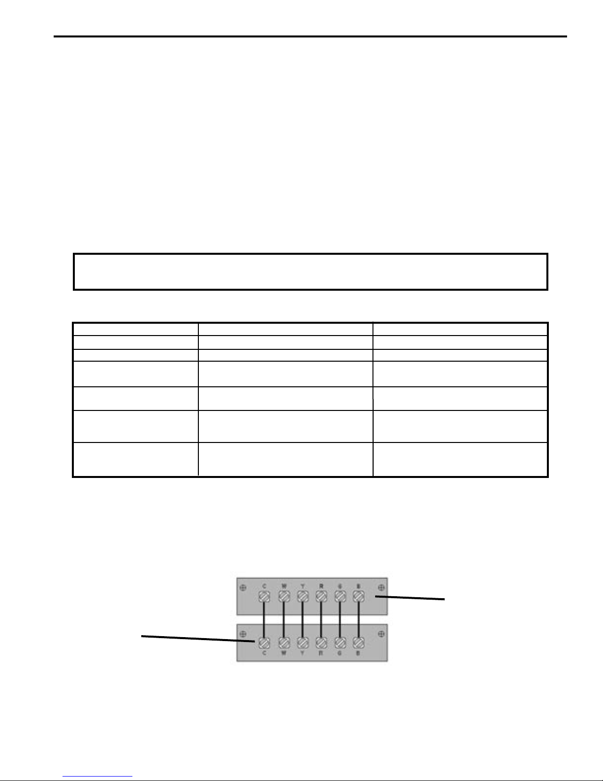
Manual Changeover Thermostat
For Heat Pump equipped units: A single stage, heat/cool thermostat with a terminal for a reversing valve operation
is required. Terminal "B" should be continuously energized in the heat mode and terminal "G" should be energized
whenever there is a call for heating or cooling. Typically, a heat/cool thermostat designed for use with electric heat
systems will meet the above requirements.
NOTE: This unit is designed for use with a single stage thermostat only. Improper application of the
thermostat may result in property damage, personal injury or death.
Honeywell Thermostat Terminal Designation
TERMINAL LETTER
Y
W
(Heat Pump units Only)
For Non-Heat Pump equipped units: A single stage cooling and heating thermostat is required. Terminal "G"
should be energized whenever a call for heating or cooling is made. Typically a heat/cool thermostat designed
for use with electric heat systems will meet this requirement.
G
C (common)
R
B
OPERATION
Cooling
Heating
Common Terminal
24 V
to the thermostat
Fan
Reversing Valve
CONTACT MADE
During call for cooling.
During call for heating.
Continuous if the slider is in the "Fan"
position, otherwise, intermittent.
For thermostats requiring a common
terminal
Directly from the transformer
Made continuously during call for
heating.
Simplified Wiring Example
Unit Terminal Board
* A-Sufx models do not have a "C" terminal
Terminal "C"
is not used on RT1
thermostat
Terminal "B" is
used for heat pump
models only.
NOTE: It is the installer's responsibility to ensure that all control wiring connections are made in accordance with
the installation instructions. Improper connection of the thermostat control wiring and/or tampering with the unit's
internal wiring can void the equipment warranty and may result in property damage, personal injury or death. Other
manufacturer's PTACs and even older Friedrich models may have different control wire connections. Questions
concerning proper connections to the unit should be directed to the factory.
Thermostat Terminals
9
Page 10
11
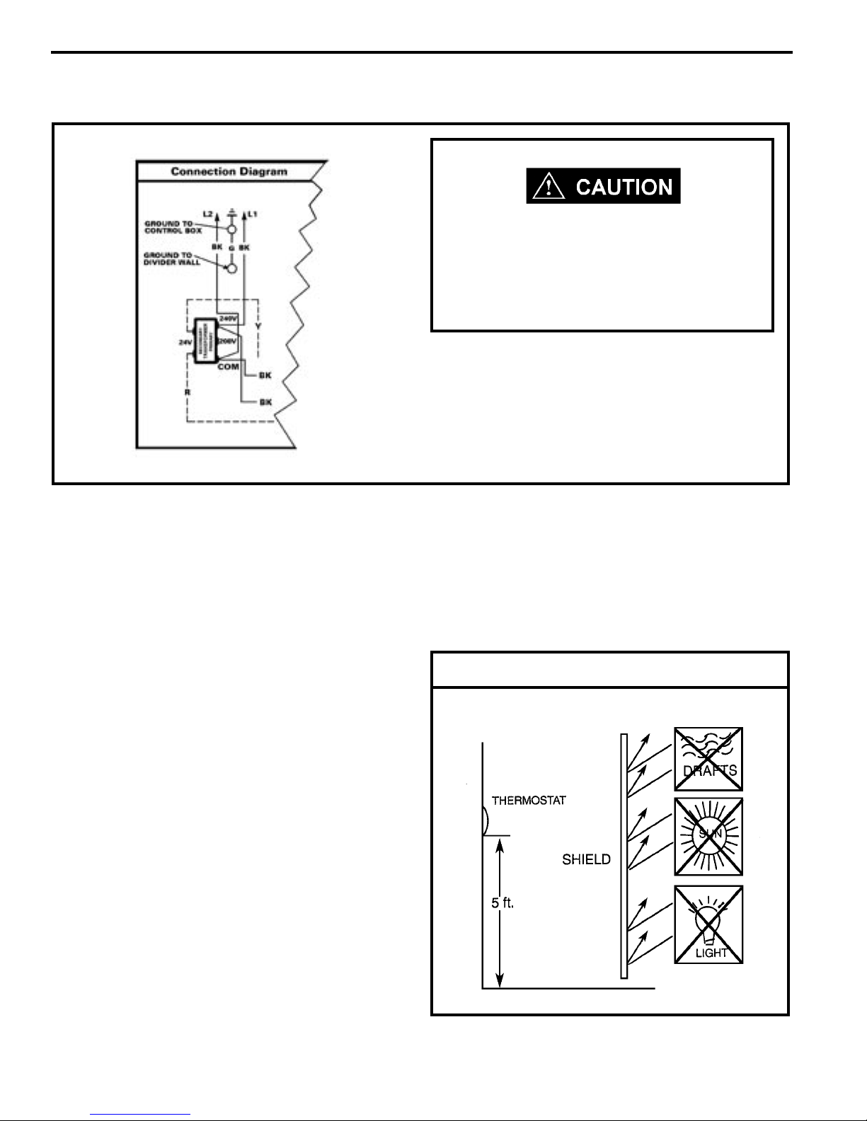
Remote Thermostat 208V Operation
208V 60HZ
If the supply voltage is 208V, the low voltage
transformer MUST be wired for 208V operation.
Failure to do so will result in lower control
voltages to the unit and can damage low voltage
components.
The simplied connection diagram at left shows the
factory congured wiring set for 240V operation. If you
are going to use 208V exclusively, switch the two (2)
black wires on the 240V post of the primary side of the
transformer to the 208V post. This will ensure correct
secondary (low) voltages for the unit. This is only required
on remote thermostat units.
Remote Thermostat Unit Operation
These units are controlled by the use of a remote
thermostat that will cycle the unit to maintain desired
room temperature. See thermostat operating instruction
sheet for details.
The fan speed switch controls high and low speed
fan operation. It is located on the control panel and is
independent of the thermostat.
Room Thermostats
Room thermostats are available from several different
manufacturers in a wide variety of styles. They range
from the very simple Bimetallic type to the complex
electronic set-back type. In all cases, no matter how
simple or complex, they are simply a switch (or series of
switches) designed to turn equipment (or components)
"ON" or "OFF" at the desired conditions.
An improperly operating, or poorly loca ted room
thermostat can be the source of perceived equipment
problems. A careful check of the thermostat and wiring
must be made then to insure that it is not the source of
problems.
the oor in an area of average temperature, with good air
circulation. Close proximity to the return air grille is the
best choice.
Mercury bulb type thermostats MUST be level to control
temperature accurately to the desired set-point. Electronic
digital type thermostats SHOULD be level for aesthetics.
Thermostat Location
Location
The thermostat should not be mounted where it may be
affected by drafts, discharge air from registers (hot or
cold), or heat radiated from the sun or appliances.
The thermostat should be located about 5 Ft. above
10
Page 11

Measuring Current Draw
Heat Anticipators
Heat anticipators are small resistance heaters (wired
in SERIES with the "W" circuit) and built into most
electromechanical thermostats. Their purpose is to prevent
wide swings in room temperature during system operation
in the HEATING mode. Since they are wired in series,
the "W" circuit will open if one burns out preventing heat
operation.
The heat anticipator provides a small amount of heat to
the thermostat causing it to cycle (turn off) the heat source
just prior to reaching the set point of the thermostat. This
prevents exceeding the set point.
If a low range ammeter is not available, a "Clamp-on" type
ammeter may be used as follows:
1. Wrap EXACTLY ten (10) turns of wire around the jaws
of a clamp-on type ammeter.
2. Connect one end of the wire to the "W" terminal of
the thermostat sub-base, and the other to the "R"
terminal.
3. Turn power on, and wait approximately 1 minute, then
read meter.
4. Divide meter reading by 10 to obtain correct anticipator
setting.
Electronic thermostats do not use a resistance type
anticipator. These thermostats use a microprocessor
(computer) that determines a cycle rate based on a program
loaded into it at the factory.
Calculating The Approximate CFM
The approximate CFM actually being delivered can be
calculated by using the following formula:
KILOWATTS x 3413
Temp. Rise x 1.08
In order to accomplish this, the heat output from the
anticipator must be the same regardless of the current
owing through it. Consequently, some thermostats have
an adjustment to compensate for varying current draw in
the thermostat circuits.
The proper setting of heat anticipators then is important to
insure proper temperature control and customer satisfaction.
A heat anticipator that is set too low will cause the heat
source to cycle prematurely possibly never reaching set
point. A heat anticipator that is set too high will cause the
heat source to cycle too late over shooting the set point.
The best method to obtain the required setting for the
heat anticipator, is to measure the actual current draw in
the control circuit ("W") using a low range (0-2.0 Amps)
ammeter. After measuring the current draw, simply set the
heat anticipator to match that value.
DO NOT simply use the Kilowatt Rating of the heater (i.e.
2.5, 3.4, 5.0) as this will result in a less-than-correct airow
calculation. Kilowatts may be calculated by multiplying the
measured voltage to the unit (heater) times the measured
current draw of all heaters (ONLY) in operation to obtain
watts. Kilowatts are then obtained by dividing by 1000.
EXAMPLE: Measured voltage to unit (heaters) is 230 volts.
Measured Current Draw of strip heaters is 11.0 amps.
230 x 11.0 = 2530
2530/1000 = 2.53 Kilowatts
2.53 x 3413 = 8635
Supply Air 95°F
Return Air 75°F
Temperature Rise 20°
20 x 1.08 = 21.6
8635
21.6
= 400 CFM
= CFM
11
Page 12
13
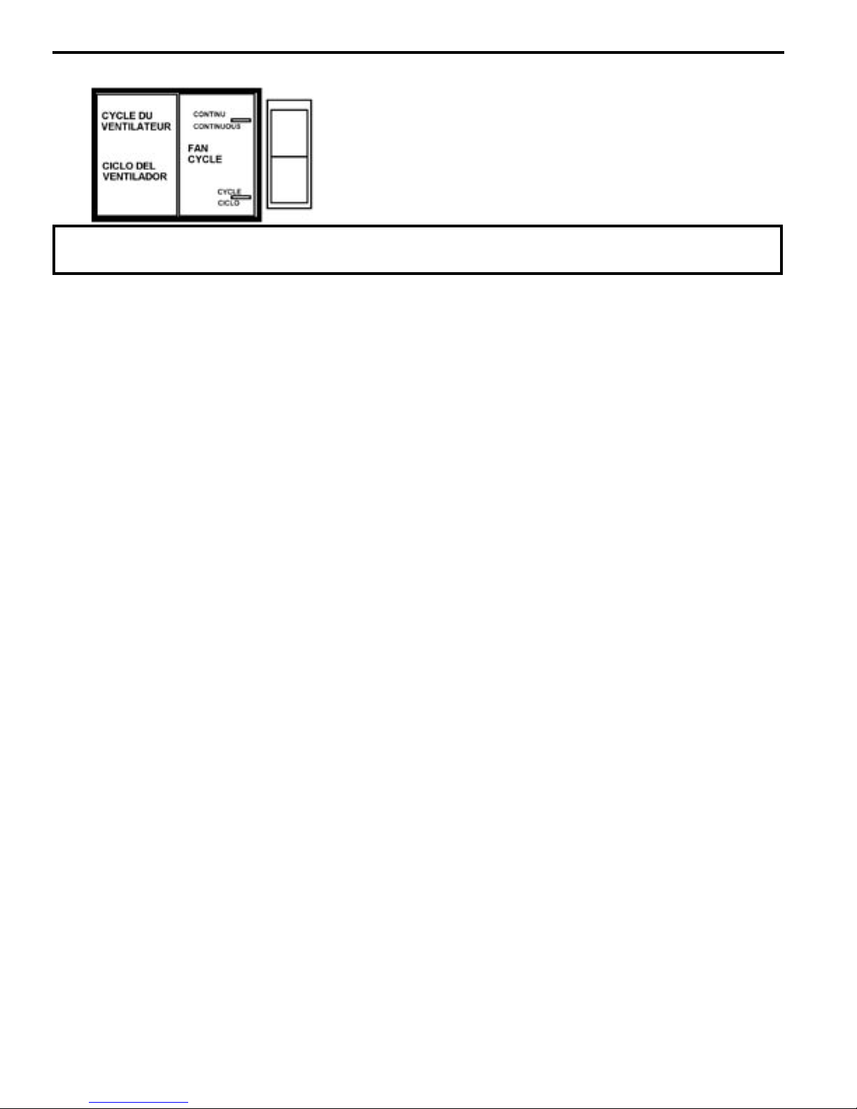
Fan Cycle Switch
NOTE: It is recommended that this switch be set in the continuous position for maximum comfort and
temperature control.
The fan cycle switch is located behind the decorative front
cover below the control box. It is designed to operate the fan
either continuously or intermittently with the compressor or
heating elements. When the switch is in the CONTINUOUS
position, the fan will run continuously when the unit is turned
on. With the fan cycle switch in the CYCLE position, the
fan will run only when the compressor or heating elements
cycle on.
Hot Start Sensor
(Heat Pump Models Only)
Under cold room conditions, the Hot Start Sensor brings
on the heater strips with a call for heat. This is to distribute warm air at the beginning of the heat cycle. Once
the return air has warmed sufciently, the heat pump
mode will begin.
Refrigerant Charging
NOTE: Because The Ptac System Is A Sealed System,
Service Process Tubes Will Have To Be Installed.
First Install A Line Tap And Remove Refrigerant From
System. Make Necessary Sealed System Repairs And
Vacuum System. Crimp Process Tube Line And Solder
End Shut. Do Not Leave A Service Valve In The Sealed
System.
Proper refrigerant charge is essential to proper unit
operation. Operating a unit with an improper refrigerant
charge will result in reduced performance (capacity) and/or
efciency. Accordingly, the use of proper charging methods
during servicing will insure that the unit is functioning as
designed and that its compressor will not be damaged.
Too much refrigerant (overcharge) in the system is just as
bad (if not worse) than not enough refrigerant (undercharge).
They both can be the source of certain compressor failures if
they remain uncorrected for any period of time. Quite often,
other problems (such as low air ow across evaporator,
etc.) are misdiagnosed as refrigerant charge problems. The
refrigerant circuit diagnosis chart will assist you in properly
diagnosing these systems.
Not enough refrigerant (undercharge) on the other hand,
will cause the temperature of the suction gas to increase to
the point where it does not provide sufcient cooling for the
compressor motor. When this occurs, the motor winding
temperature will increase causing the motor to overheat
and possibly cycle open the compressor overload protector.
Continued overheating of the motor windings and/or cycling
of the overload will eventually lead to compressor motor
or
overload failure.
Method Of Charging
The acceptable method for charging the PTAC system is
the Weighed in Charge Method. The weighed in charge
method is applicable to all units. It is the preferred method
to use, as it is the most accurate.
The weighed in method should always be used whenever
a charge is removed from a unit such as for a leak repair,
compressor replacement, or when there is no refrigerant
charge left in the unit. To charge by this method, requires
the following steps:
1. Install a piercing valve to remove refrigerant from the
sealed system. (Piercing valve must be removed from
the system before recharging.)
2. R e c o v e r Re f r i g e r a n t in accordance with EPA
regulations.
3. Install a process tube to sealed system.
4. Make necessary repairs to system.
An overcharged unit will at times return liquid refrigerant
(slugging) back to the suction side of the compressor
eventually causing a mechanical failu re within the
compressor. This mechanical failure can manifest itself
as valve failure, bearing failure, and/or other mechanical
failure. The specic type of failure will be inuenced by the
amount of liquid being returned, and the length of time the
slugging continues.
12
5. Evacuate system to 300 microns or less.
6. Weigh in refrigerant with the property quantity of R-22
refrigerant.
7. Start unit, and verify performance.
8. Crimp the process tube and solder the end shut.
Page 13

NOTE: In order to access the sealed system it will be necessary to install Schrader
type ttings to the process tubes on the discharge and suction of the compressor.
Proper recovery refrigerant procedures need to be adhered to as outlined in EPA
Regulations. THIS SHOULD ONLY BE ATTEMPTED BY QUALIFIED SERVICE
PERSONNEL.
Undercharged Refrigerant Systems
An undercharged system will result in poor performance (low
pressures, etc.) in both the heating and cooling cycle.
Whenever you service a unit with an undercharge of
refrigerant, always suspect a leak. The leak must be
repaired before charging the unit.
To check for an undercharged system, turn the unit on, allow
the compressor to run long enough to establish working
pressures in the system (15 to 20 minutes).
During the cooling cycle you can listen carefully at the exit
of the metering device into the evaporator; an intermittent
hissing and gurgling sound indicates a low refrigerant
charge. Intermittent frosting and thawing of the evaporator
is another indication of a low charge, however, frosting
and thawing can also be caused by insufcient air over
the evaporator.
Checks for an undercharged system can be made at the
compressor . If the compressor seems quieter than normal,
it is an indication of a low refrigerant charge. A check of the
amperage drawn by the compressor motor should show a
lower reading. (Check the Unit Specication.) After the unit
has run 10 to 15 minutes, check the gauge pressures.
Gauges connected to system with an undercharge will
have low head pressures and substantially low suction
pressures.
13
Page 14

15
Overcharged Refrigerant Systems
Com p r e s s or amps will be near norm a l or higher.
Noncondensables can also cause these symptoms. To
conrm, remove some of the charge, if conditions improve,
system may be overcharged. If conditions don’t improve,
Noncondensables are indicated.
Whenever an overcharged system is indicated, always
make sure that the problem is not caused by air ow
problems. Improper air ow over the evaporator coil may
indicate some of the same symptoms as an overcharged
system.
An over charge can cause the compressor to fail, since it
would be "slugged" with liquid refrigerant.
The charge for any system is critical. When the compressor
is noisy, suspect an overcharge, when you are sure that
the air quantity over the evaporator coil is correct. Icing
of the evaporator will not be encountered because the
refrigerant will boil later if at all. Gauges connected to
system will usually have higher head pressure (depending
upon amount of overcharge). Suction pressure should be
slightly higher.
14
Page 15

Restricted Refrigerant System
Troubleshooting a restricted refrigerant system can
be difcult. The following procedures are the more
common problems and solutions to these problems.
There are two types of refrigerant restrictions: Partial
restrictions and complete restrictions.
A partial restriction allows some of the refrigerant to
circulate through the system.
With a complete restriction there is no circulation of
refrigerant in the system.
Restricted refrigerant systems display the same symptoms
as a "low-charge condition."
When the unit is shut off, the gauges may equalize very
slowly.
Gauges connected to a completely restricted system will run
in a deep vacuum. When the unit is shut off, the gauges
will not equalize at all.
A quick check for either condition begins at the evaporator.
With a partial restriction, there may be gurgling sounds
at the metering device entrance to the evaporator. The
evaporator in a partial restriction could be partially frosted
or have an ice ball close to the entrance of the metering
device. Frost may continue on the suction line back to the
compressor.
Often a partial restriction of any type can be found by feel,
as there is a temperature difference from one side of the
restriction to the other.
With a complete restriction, there will be no sound at the
metering device entrance. An amperage check of the
compressor with a partial restriction may show normal
current when compared to the unit specication. With a
complete restriction the current drawn may be considerably
less than normal, as the compressor is running in a deep
vacuum (no load.) Much of the area of the condenser will
be relatively cool since most or all of the liquid refrigerant
will be stored there.
The following conditions are based primarily on a system
in the cooling mode.
15
Page 16

17
Metering Device
Capillary Tube Systems
All units are equipped with capillary tube metering devices.
Checking for restricted capillary tubes.
3. Switch the unit to the heating mode and observe the
gauge readings after a few minutes running time. If
the system pressure is lower than normal, the heating
capillary is restricted.
1. Connect pressure gauges to unit.
2. Start the unit in the cooling mode. If after a few
minutes of operation the pressures are normal,
the check valve and the cooling capillary are not
restricted.
Reversing Valve
Description/Operation
The Reversing Valve controls the direction of refrigerant
ow to the indoor and outdoor coils. It consists of a
pressure-operated, main valve and a pilot valve actuated
by a solenoid plunger. The solenoid is energized during
the heating cycle only. The reversing valves used in the
PTAC system is a 2-position, 4-way valve
The single tube on one side of the main valve body is the
high-pressure inlet to the valve from the compressor. The
center tube on the opposite side is connected to the low
pressure (suction) side of the system. The other two are
connected to the indoor and outdoor coils. Small capillary
tubes connect each end of the main valve cylinder to the
"A" and "B" ports of the pilot valve. A third capillary is a
common return line from these ports to the suction tube
on the main valve body. Four-way reversing valves also
have a capillary tube from the compressor discharge tube
to the pilot valve.
4. If the operating pressures are lower than normal in both
the heating and cooling mode, the cooling capillary is
restricted.
DANGER OF BODILY INJURY OR DEATH
FROM ELECTRICAL SHOCK
The reversing valve solenoid is connected to
high voltage. Turn off electrical power before
disconnecting or connecting high voltage wiring
or servicing valve.
The piston assembly in the main valve can only be shifted
by the pressure differential between the high and low
sides of the system. The pilot section of the valve opens
and closes ports for the small capillary tubes to the main
valve to cause it to shift.
NOTE: System operating pressures must be near
normal before valve can shift.
16
Page 17

Electrical Circuit and Coil
(Reversing valve coil is energized in the heating cycle only).
1. Set controls for heating; valve should shift if there is
pressure in the sealed system.
2. REMOTE THERMOSTAT HEAT PUMP UNITS: Check
for line voltage at the heat relay, terminal #4 and the
reversing valve relay terminal #4. If voltage isn't present,
test the heat relay and the reversing valve relay.
3. STANDARD HEAT PUMP UNITS: Check for line voltage
at system switch terminal #7 and thermostat terminal #2.
If voltage is not present, test the system switch.
Testing Coil
1. Turn off high voltage electrical power to unit.
2. Unplug line voltage lead from reversing valve coil.
3. Check for electrical continuity through the coil. If you
do not have continuity replace the coil.
4. Check from each lead of coil to the copper liquid line as
it leaves the unit or the ground lug. There should be no
continuity between either of the coil leads and ground;
if there is, coil is grounded and must be replaced.
5. If coil tests okay, reconnect the electrical leads .
6. Make sure coil has been assembled correctly.
Reversing Valve in Heating Mode
Touch Test in Heating/Cooling Cycle
The only definite indications that the slide is in the
mid-position is if all three tubes on the suction side of the
valve are hot after a few minutes of running time.
Checking the Reversing Valve
NOTE: You must have normal operating pressures before
the reversing valve can shift.
Check for proper refrigerant charge. Sluggish or sticky
reversing valves can sometimes be remedied by reversing
the valve several time with the airow restricted to increase
system pressure.
To raise head pressure during the cooling season the airow
through the outdoor coil can be restricted . During heating
the indoor air can be restricted by blocking the return air.
Dented or damaged valve body or capillary tubes can
prevent the main slide in the valve body from shifting.
If you determine this is the problem, replace the reversing
valve.
After all of the previous inspections and checks have been
made and determined correct, then perform the "Touch Test"
on the reversing valve.
NOTE: A condition other than those illustrated above, and
on Page 28, indicate that the reversing valve is not shifting
properly. Both tubes shown as hot or cool must be the same
corresponding temperature.
Procedure For Changing Reversing
Valve:
1. Install Process Tubes. Recover refrigerant
from sealed system. PROPER HANDLING OF
RECOVERED REFRIGERANT ACCORDING TO
EPA REGULATIONS IS REQUIRED.
2. Remove solenoid coil from reversing valve. If coil is to
be reused, protect from heat while changing valve.
3. Unbraze all lines from reversing valve.
4. Clean all excess braze from all tubing so that they will
slip into ttings on new valve.
5. Remove solenoid coil from new valve.
6. Protect new valve body from heat while brazing with
plastic heat sink (ThermoTrap) or wrap valve body with
wet rag.
Never energize the coil when
it is removed from the valve
as a coil burnout will result.
7. Fit all lines into new valve and braze lines into new
valve.
17
Page 18

19
Reversing Valve in Cooling Mode
8. Pressurize sealed system with a combination of R-22
and nitrogen and check for leaks, using a suitable leak
detector. Recover refrigerant per EPA guidelines.
9. Once the sealed system is leak free, install solenoid coil
on new valve and charge the sealed system by weighing
in the proper amount and type of refrigerant as shown
on rating plate. Crimp the process tubes and solder the
ends shut. Do not leave Schrader or piercing valves in
the sealed system.
Make sure that the ends of the lead do not touch
the compressor shell since this will cause a short
circuit.
Determine L.R.V.
Start the compressor with the voltmeter attached; then stop
the unit. Attempt to restart the compressor within a couple
of seconds and immediately read the voltage on the meter.
The compressor under these conditions will not start and will
usually kick out on overload within a few seconds since the
pressures in the system will not have had time to equalize.
Voltage should be at or above minimum voltage of 197 VAC,
as specied on the rating plate. If less than minimum, check
for cause of inadequate power supply; i.e., incorrect wire
size, loose electrical connections, etc.
AMPERAGE (L.R.A.) TEST
The running amperage of the compressor is the most
important of these readings. A running amperage higher
than that indicated in the performance data indicates that
a problem exists mechanically or electrically.
Single Phase Running and L.R.A. Test
NOTE: Consult the specication and performance section
for running amperage. The L.R.A. can also be found on
the rating plate.
Select the proper amperage scale and clamp the meter probe
around the wire to the "C" terminal of the compressor.
DANGER OF BODILY INJURY OR
DEATH FROM ELECTRICAL SHOCK
When working on high voltage equipment - turn the
electrical power off before attaching test leads.
Use test leads with alligator type clips - clip to
terminals, turn power on, take reading - turn power
off before removing leads.
Compressor Checks
LOCKED ROTOR VOLTAGE (L.R.V.) TEST
Locked rotor voltage (L.R.V.) is the actual voltage available
at the compressor under a stalled condition.
Single Phase Connections
Disconnect power from unit. Using a voltmeter, attach one
lead of the meter to the run "R" terminal on the compressor
and the other lead to the common "C" terminal of the
compressor. Restore power to unit.
Turn on the unit and read the running amperage on the
meter. If the compressor does not start, the reading will
indicate the locked rotor amperage (L.R.A.).
External Overload
The compressor is equipped with an external overload which
senses both motor amperage and winding temperature.
High motor temperature or amperage heats the overload
causing it to open, breaking the common circuit within the
compressor.
Heat generated within the compressor shell, usually due
to recycling of the motor, is slow to dissipate. It may take
anywhere from a few minutes to several hours for the
overload to reset.
Checking the External Overload
With power off, remove the leads from compressor terminals.
If the compressor is hot, allow the overload to cool before
starting check. Using an ohmmeter, test continuity across
the terminals of the external overload. If you do not have
continuity; this indicates that the overload is open and must
be replaced.
18
Page 19

Many compressor failures are caused by the following
conditions:
1. Improper air ow over the evaporator.
2. Overcharged refrigerant system causing liquid to be
returned to the compressor.
3. Restricted refrigerant system.
4. Lack of lubrication.
5. Liquid refrigerant returning to compressor causing oil
to be washed out of bearings.
6. Noncon dens ables such as air and moisture in
the system. Moisture is extremely destructive to a
refrigerant system.
Recommended procedure for
compressor replacement
NOTE: Be sure power source is off, then disconnect all
wiring from the compressor.
Single Phase Resistance Test
Remove the leads from the compressor terminals and set
the ohmmeter on the lowest scale (R x 1).
Touch the leads of the ohmmeter from terminals common
to start ("C" to "S"). Next, touch the leads of the ohmmeter
from terminals common to run ("C" to "R").
Add values "C" to "S" and "C" to "R" together and
check resistance from start to run terminals ("S" to "R").
Resistance "S" to "R" should equal the total of "C" to "S"
and "C" to "R."
In a single phase PSC compressor motor, the highest value
will be from the start to the run connections (“S” to "R").
The next highest resistance is from the start to the common
connections ("S" to "C"). The lowest resistance is from the
run to common. ("C" to "R") Before replacing a compressor,
check to be sure it is defective.
Check the complete electrical system to the compressor and
compressor internal electrical system, check to be certain
that compressor is not out on internal overload.
Complete evaluation of the system must be made whenever
you suspect the compressor is defective. If the compressor
has been operating for some time, a careful examination
must be made to determine why the compressor failed.
1. Be certain to perform all necessary electrical and
refrigeration tests to be sure the compressor is actually
defective before replacing .
2. Recover all refrigerant from the system though
the process tubes. PROPER HANDLIN G OF
RECOVERED REFRIGERANT ACCORDING TO EPA
REGULATIONS IS REQUIRED. Do not use gauge
manifold for this purpose if there has been a burnout.
You will contaminate your manifold and hoses. Use a
Schrader valve adapter and copper tubing for burnout
failures.
3. After all refrigerant has been recovered, disconnect
suction and discharge lines from the compressor and
remove compressor. Be certain to have both suction
and discharge process tubes open to atmosphere.
19
Page 20

21
4. Carefully pour a small amount of oil from the suction
st ub of t he defec tive co mpresso r into a clean
container.
5. Using an acid test kit (one shot or conventional kit),
test the oil for acid content according to the instructions
with the kit.
6. If any evidence of a burnout is found, no matter how
slight, the system will need to be cleaned up following
proper procedures.
7. Install the replacement compressor.
8. Pressurize with a combination of R-22 and nitrogen
and leak test all connections with an electronic or
Halide leak detector. Recover refrigerant and repair
any leaks found.
Repeat Step 8 to insure no more leaks are present.
9. Evacuate the system with a good vacuum pump
capable of a nal vacuum of 300 microns or less.
The system should be evacuated through both liquid
line and suction line gauge ports. While the unit is
being evacuated, seal all openings on the defective
compressor. Compressor manufacturers will void
warranties on units received not properly sealed. Do
not distort the manufacturers tube connections.
10. Recharge the system with the correct amount of
refrigerant. The proper refrigerant charge will be
found on the unit rating plate. The use of an accurate
measuring device, such as a charging cylinder,
electronic scales or similar device is necessary.
Hazard of shock and electrocution. A capacitor can
hold a charge for long periods of time. A service
technician who touches these terminals can be
injured. Never discharge the capacitor by shorting
across the terminals with a screwdriver.
CAPACITORS
Many motor capacitors are internally fused. Shorting the
terminals will blow the fuse, ruining the capacitor. A 20,000
ohm 2 watt resistor can be used to discharge capacitors
safely. Remove wires from capacitor and place resistor
across terminals. When checking a dual capacitor with
a capacitor analyzer or ohmmeter, both sides must be
tested.
Capacitor Check With Capacitor
Analyzer
The capacitor analyzer will show whether the capacitor is
"open" or "shorted." It will tell whether the capacitor is within
its microfarads rating and it will show whether the capacitor
is operating at the proper power-factor percentage. The
instrument will automatically discharge the capacitor when
the test switch is released
Capacitor Connections
The starting winding of a motor can be damaged by a
shorted and grounded running capacitor. This damage
usually can be avoided by proper connection of the running
capacitor terminals.
From the supply line on a typical 230 volt circuit, a 115 volt
potential exists from the "R" terminal to ground through a
possible short in the capacitor. However, from the "S" or start
terminal, a much higher potential, possibly as high as 400
volts, exists because of the counter EMF generated in the
start winding. Therefore, the possibility of capacitor failure
is much greater when the identied terminal is connected
to the “S" or start terminal. The identied terminal should
always be connected to the supply line, or "R" terminal,
never to the "S" terminal.
Wh en conne cted pro perly, a shorted or grou n ded
running-capacitor will result in a direct short to ground
from the "R" terminal and will blow the line fuse. The motor
protector will protect the main winding from excessive
temperature.
20
Page 21

System Switch Continuity Check
ROTATE SHAFT
(VIEWED FROM THE FRONT)
CLOCKWISE TO
STOP
COUNTER CLOCKWISE
TO ST
OP
READ CONTINUITY BETWEEN
2(C) & 3(L)
2(C) & 1(H)
Thermostat
Rear View
3
2
1
L
C
H
Remove and label all wires from the system switch. Using an ohmmeter checks for continuity can be made. Continuity
reading should be as shown in the table below. Should the switch fail any part of this check it should be replaced.
CONTACTS MADE
Cooling
Only
Models
Cooling /
Heating
Models
OFF
HIGH COOL
FAN ONLY
LOW COOL
CONTACTS MADE
OFF
LOW COOL
HIGH COOL
FAN ONLY
HIGH HEAT
LOW HEAT
NONE
L1 TO 2,3 TO COMP.
4 TO H, COM TO L2
1 TO H COM TO L2
L1 TO 2, 3 TO COMP.
L TO 4, COM TO L2
NONE
L1 TO 2, 5 TO 3, 4 TO 6
L TO 9, COM TO L2
L1 TO2, 5 TO 3, 4 TO 6
H TO 9, COM TO L2
8 TO H, COM TO L2
L1 TO 8
L1 TO 2, 5 TO 1, 7 TO 6
H TO 9, COM TO L2
L1 TO 2, 5 TO 1, 7 TO 6
L TO 9 COM TO L2
Thermostat Continuity Check
Remove and label all wires from the thermostat. To check out the thermostat on cooling the thermostat bulb must be
above 60 degrees. Using an ohmmeter checks for continuity can be made. Continuity reading should be as shown in
the table below. Should the thermostat fail any part of this check it should be replaced.
(Some thermostats may have the terminals identied by the letters C, H and L)
21
Page 22

23
Fan Cycle Switch
Continuity Check
Remove and label all wires from the fan cycle switch. Continuity reading should be as shown in the table below. Should
the fan cycle switch fail any part of this check, it should be replaced.
Fan Speed Switch
Continuity Check
(Remote Models Only)
Remove and label all wires from the fan speed switch. Continuity reading should be as shown in the table below. Should
the fan speed switch fail any part of this check, it should be replaced.
22
Page 23

Emergency Heat Switch (Defrost Thermostat)
Continuity Check
Electric Heat Switch Operation ( Heat Pumps Only)
The electric heat switch is a dual function control and is shown on the wiring diagram as a defrost thermostat. It may
be adjusted using a screwdriver. As the control shaft is rotated counter clockwise a detent will be encountered. Turning
the control past the detent will lock out the compressor and acts as an emergency heat switch. Turning the control shaft
clockwise will lower the change over point for compressor operation. The control it self is a double throw, single pole switch
operated by a bellows and a gas lled capillary tube. The capillary tube senses a combination of outdoor coil temperature
and outdoor air temperature. As the combined temperatures reach a point that the outdoor coil is iced, where heat
pump operation is no longer efcient, the control shuts off the compressor and turns on the electric heat. At its lowest
setting the cut off point is approximately 25 degrees, the highest setting is 52 degrees, with a 10 degree differential. It
is possible, under certain conditions, for the unit to cycle between compressor and electric heat operation.
Electric Heat Switch Check Out
The switch may be checked out with an ohmmeter. Remove and label the three wires from the switch. Terminal 2 is
common and the contacts make to Terminal 3 on temperature rise and to Terminal 1 on temperature fall. With the
control set in the emergency heat position continuity should be read between Terminal 2 and Terminal 1 regardless of
coil temperature. As the control shaft is rotated clockwise, through the adjustment range, continuity will be read between
Terminal 2 and Terminal 3, providing the temperature of the capillary tube is above 25º (± 5%). If the temperature at the
capillary tube is above approximately 52 degrees it may be necessary to place the end of the capillary tube in ice water
to determine if the control is sensing temperature changes. Should the control lose the gas charge in the capillary tube
it will fail to the electric heat position and the compressor will not operate.
(Some thermostats may have the terminals identied by the letters C, H and L)
L
C
H
SWITCH
POSITION
TEMPERATURE
AT CAPILLARY
CONTINUITY READ
EMERGENCY HEAT N/A 1(H) and 2(C) = Electric Heat
ANYWHERE IN
ADJUSTMENT RANGE
ABOVE
SET POINT
2(C) and 3(L) = Compressor
ANYWHERE IN
ADJUSTMENT RANGE
BELOW
SET POINT
1(H) and 2(C) = Electric Heat
23
Page 24

25
Routine Maintenance
NOTE: Units are to be inspected and serviced by qualied service personnel only.
1. Clean the unit air intake lter at least every 300 to 350 hours of operation. Clean the lters with a mild detergent in
warm water and allow to dry thoroughly before reinstalling.
2. The indoor coil (evaporator coil), the outdoor coil (condenser coil) and base pan should be inspected periodically
(yearly or bi-yearly) and cleaned of all debris (lint, dirt, leaves, paper, etc.). Clean the coils and base pan with a soft
brush and compressed air or vacuum. If using a pressure washer, be careful not to bend the aluminium n pack.
Use a sweeping up and down motion in the direction of the vertical aluminum n pack when pressure cleaning
coils. Cover all electrical components to protect them from water or spray. Allow the unit to dry thoroughly before
reinstalling it in the sleeve.
NOTE: Do not use a caustic coil cleaning agent on coils or base pan. Use a biodegradable cleaning agent and
degreaser.
Inspect the indoor blower housing, evaporator blade, condenser fan blade, and condenser shroud periodically (yearly
or bi-yearly) and clean of all debris (lint, dirt, mold, fungus, etc.) Clean the blower housing area and blower wheel
with an antibacterial / antifungal cleaner. Use a biodegradable cleaning agent and degreaser on condenser fan
and condenser shroud. Use warm or cold water when rinsing these items. Allow all items to dry thoroughly before
reinstalling them.
3. Periodically (at least yearly or bi-yearly): inspect all control components, both electrical and mechanical, as well
as the power supply. Use proper testing instruments (voltmeter, ohmmeter, ammeter, wattmeter, etc.) to perform
electrical tests. Use an air conditioning or refrigeration thermometer to check room, outdoor and coil operating
temperatures. Use a sling psychrometer to measure wet bulb temperatures indoors and outdoors.
4. Inspect the surrounding area (inside and outside) to ensure that the units' clearances have not been compromised
or altered.
5. Inspect the sleeve and drain system periodically (at least yearly or bi-yearly) and clean of all obstructions and debris.
Clean both areas with an antibacterial and antifungal cleaner. Rinse both items thoroughly with water and ensure
that the drain outlets are operating correctly. Check the sealant around the sleeve and reseal areas as needed.
6. Clean the front cover when needed. Use a mild detergent. Wash and rinse with warm water. Allow it to dry thoroughly
before reinstalling it in the chassis.
Discharge Air Grille
Filters
Return Air Grille
Blower Wheel
Indoor Blower Housing
Gasket
Control Door
Front Cover
Evaporator Coil
Control Panel
Condenser Fan Blade
Condenser
Shroud
Gasket
Condenser
Coil
Compressor
Basepan
Outdoor Grille
Wall Sleeve
24
Page 25

Troubleshooting Chart — Cooling
REFRIGERANT SYSTEM
DIAGNOSIS COOLING
Low Suction Pressure High Suction Pressure Low Head Pressure High Head Pressure
Low Load Conditions High Load Conditions Low Load Conditions High Load Conditions
Low Air Flow Across High Air Flow Across Refrigerant System Low Air Flow Across
Indoor Coil Indoor Coil Restriction Outdoor Coil
Refrigerant System Reversing Valve not Reversing Valve not
Restriction Fully Seated Fully Seated
Undercharged Overcharged Undercharged Noncondendsables (air)
in System
Moisture in System Defective Compressor Defective Compressor
Overcharged
25
Page 26

27
Troubleshooting Chart — Heating
REFRIGERANT SYSTEM
DIAGNOSIS – HEATING
Low Suction Pressure High Suction Pressure Low Head Pressure High Head Pressure
Low Airow
Across Outdoor Coil
Refrigerant System
Restriction
Undercharged Overcharged
Moisture in System
Outdoor Ambient Too High
for Operation in Heating
Reversing Valve not
Fully Seated
Defective Compressor Defective Compressor
Refrigerant System
Restriction
Reversing Valve not
Fully Seated
Undercharged
Outdoor Ambient Too High
For Operation In Heating
Low Airow Across
Indoor Coil
Overcharged
Non-condensables (air) in
System
26
Page 27

Electrical Troubleshooting Chart
HEAT PUMP
HEAT PUMP
SYSTEM COOLS WHEN
HEATING IS DESIRED.
Is Line Voltage
Present at the Solenoid
Valve?
YES
Is the Solenoid Coil Good?
YES
Reversing Valve Stuck
Replace the Reversing Valve
NO
NO
Is the Selector Switch
Set for Heat?
Replace the Solenoid Coil
27
Page 28

29
Wiring Diagram PTAC Models PE ( 07, 09, 12, 15 ) KOOSA-1
Wiring Diagram PTAC Models PH ( 07, 09, 12, 15 ) K (2, 3, 5 ) SA-1
28
Page 29

Wiring Diagram PTAC Models PH ( 07, 09, 12, 15 ) KOOSA-1
Wiring Diagram PTAC Models PE ( 07, 09, 12, 15 ) K ( 2, 3, 5 ) SA-1
29
Page 30

31
Wiring Diagram PTAC Models PH ( 07, 09, 12, 15 ) K ( 2, 3, 5 ) RA-1
Wiring Diagram PTAC Models PE ( 07, 09, 12, 15 ) K ( 2, 3, 5 ) RA-1
30
Page 31

Wiring Diagram PTAC Models PE ( 07, 09, 12, 15 ) KOORA-1
Wiring Diagram PTAC Models PE ( 07, 09, 12, 15 ) R00SA-1
31
Page 32

33
Wiring Diagram PTAC Models PE ( 07, 09, 12, 15 ) R ( 2, 3, 5 ) SA-1
Wiring Diagram PTAC Models PH ( 07, 09, 12, 15 ) R ( 2, 3, 5 ) SA-1
32
Page 33

Wiring Diagram PTAC Models PE ( 07, 09, 12, 15 ) R ( 2, 3, 5 ) RA-1
Wiring Diagram PTAC Models PH ( 07, 09, 12, 15 ) R ( 2, 3, 5 ) RA-1
33
Page 34

35
Wiring Diagram PTAC Models PE (07, 09, 12, 15) K005 S-1
FAN
HERM
c
S
C
R
1(H)
3(L)
2(C)
4
L
3
CO
M
H
L1
L2
1
2
COMP
1
3
2
RED
BLACK
FAN
CAPACITO
R
BROWN
YELLOW
TO INNERWALL
GREE
N
SMOOTH
RIBBED
SUPPLY CORD
TO CONTROL BO
X
RED
BLU
E
COMPRESSOR
MOTOR
BLACK
RED
BLACK
INDOOR
BLUE
RED
BLACK BLAC
K
YELLO
W
SYSTEM
SWITCH
FAN CYCLE
HEAT
T-STAT
SWITCH
ANTICIPATOR
BLU
E
260-400-00
REVPART NO.
ORANGE
ORANGE
BLUE
L1 TO 2, 3 TO COMP,
1 TO H COM TO L2
4 TO H, COM TO L2
L1 TO 2, 3 TO COMP,
WIRING DIAGRAM PTAC MODELS
NONE
OFF
L TO 4, COM TO L2
LOW COOL
FAN ONLY
HI COOL
CONTACTS MADE
HAZARD DISCONNECT POWER
BEFORE SERVICING
DANGER: ELECTRICAL SHOCK
4
1
5
2
OPTIONAL FIELD DESK CONTROL WIRING
DESK CONTROL RELAY
00
WHITE WIRE
(SUPPLIED)
(SUPPLIED)
BLACK WIRE
TO UNIT SWITCH
TERMINAL "L2"
TERMINAL "L1"
TO UNIT SWITCH
CORD
VOLT WIRES.
FIELD SUPPLIED 24
WIRING HARNESS &
RIBBED WIRE
SMOOTH WIRE
POWER
FAN
5
HERM
c
3
4
1
C(2)
L(3)
H(1)
S
C
R
H(1)
L(3)
C(2)
9
5
L
6
COM
H
L1
L2
31
8
2
7
4
1
3
2
RED
BLACK
FAN
HEATER
SOLENOID
CAPACITOR
HOT START
SENSOR
BROWN
RED
BROWN
YELLOW
TO INNERWALL
GREEN
SMOOTH
RIBBED
SUPPLY CORD
TO CONTROL BOX
BROWN
HOT START
RELAY
BLACK
RED
BLUE
DEFROST
BROWN
BROWN
RED
COMPRESSOR
COIL
T-STAT
MOTOR
BLACK
RED
BLACK
INDOOR
RED
BLUE
RED
BLACK BLACK
YELLOW
BLUE
TAN
SYSTEM
SWITCH
FAN CYCLE
HEAT
T-STAT
SWITCH
ANTICIPATOR
BLUE
WHITE
RED
BLUE
260-401-10
REVPART NO.
ORANGE
ORANGE
BLACK
BLACK
L TO 9, COM TO L2
L1 TO 2, 5 TO 1, 7 TO
6
H TO 9, COM TO L2
L1 TO 2, 5 TO 1, 7 TO
6
8 TO H, COM TO L2,
H TO 9, COM TO L2
L1 TO 2, 5 TO 3, 4 TO
6
L TO 9, COM TO L2
L1 TO 2, 5 TO 3, 4 TO
6
WIRING DIAGRAM PTAC MODELS
NONEOFF
L1 TO
8
LOW HEAT
HI HEAT
FAN ONLY
HI COOL
LOW COOL
CONTACTS MADE
HAZARD DISCONNECT POWER
BEFORE SERVICING
DANGER: ELECTRICAL SHOC
K
DESK CONTROL RELAY
OPTIONAL FIELD DESK CONTROL WIRING
CORD
SMOOTH WIRE
RIBBED WIRE
VOLT WIRES.
FIELD SUPPLIED 24
WIRING HARNESS &
4
1
5
2
POWER
TERMINAL "L1"
TERMINAL "L2"
TO UNIT SWITCH
(SUPPLIED)
BLACK WIRE
(SUPPLIED)
WHITE WIRE
TO UNIT SWITCH
00
Wiring Diagram PTAC Models PH (07, 09, 12, 15) K (2, 3, 5) SB-1
34
Page 35

Wiring Diagram PTAC Models PE (07, 09, 12, 15) K (2, 3, 5) SB-1
FAN
HERM
c
S
C
R
1(H)
3(L)
2(C)
9
5
L
6
COM
H
L1
L2
31
8
2
7
4
1
3
2
RED
BLACK
FAN
HEATER
CAPACITOR
TAN
RED
BROWN
YELLOW
TO INNERWALL
GREEN
SMOOTH
RIBBED
SUPPLY CORD
TO CONTROL BOX
RED
BLUE
COMPRESSOR
MOTOR
BLACK
RED
BLACK
INDOOR
RED
BLUE
RED
BLACK BLACK
YELLOW
BLUE
SYSTEM
SWITCH
FAN CYCLE
HEAT
T-STAT
SWITCH
ANTICIPATOR
BLUE
260-403-00
REVPART NO.
BLACK
ORANGE
ORANGE
L TO 9, COM TO L2
L1 TO 2, 5 TO 1, 7 TO
6
H TO 9, COM TO L2
L1 TO 2, 5 TO 1, 7 TO
6
8 TO H, COM TO L2,
H TO 9, COM TO L2
L1 TO 2, 5 TO 3, 4 TO
6
L TO 9, COM TO L2
L1 TO 2, 5 TO 3, 4 TO
6
WIRING DIAGRAM PTAC MODELS
NONEOFF
L1 TO
8
LOW HEAT
HI HEAT
FAN ONLY
HI COOL
LOW COOL
CONTACTS MADE
HAZARD DISCONNECT POWER
BEFORE SERVICING
DANGER: ELECTRICAL SHOC
K
00
DESK CONTROL RELAY
OPTIONAL FIELD DESK CONTROL WIRING
4
1
5
2
CORD
SMOOTH WIRE
RIBBED WIRE
VOLT WIRES.
FIELD SUPPLIED 24
WIRING HARNESS &
POWER
TERMINAL "L1"
TERMINAL "L2"
TO UNIT SWITCH
(SUPPLIED)
BLACK WIRE
(SUPPLIED)
WHITE WIRE
TO UNIT SWITCH
24V
240V
208V
COM
HERM
YELLOW
RED
FAN
2
1
BLACK
RED
MOTOR
TERM BOARD
PURPLE
YELLOW
BLUE
ORANGE
W
3
Y
R
G B
HEATING
HEATER
FAN SPEED
BLUE
COIL
SOLENOI
D
1
4
2
6
3
CAPACITOR
SENSOR
HOT START
BROWN
TAN
BROWN
WHITE
FAN
BROWN
YELLO
W
c
RELAY
DEFROST
T-STAT
COOLING RELAY
TO INNERWALL
RED
TRANSFORMER
RIBBED
SMOOTH
BLACK
BLACK
FAN
WHITE
BLUE
BLACK
4
1
2
3
BROWN
5
3
1
4
PURPLE
1
2
3
4
BROWN
RE
D
YELLOW
BROWN
L(3)
C(2)
SUPPLY CORD
TO CONTROL BOX
GREEN
SUCTION LINE
THERMOSTAT
BLACK
BLACK
H(1)
COMPRESSOR
C
R
S
HOT START
BLACK
BLU
E
RED
REV
260-404-10
PART NO.
1
3
4
2
WHITE
RED
BLACK
BLACK
BLACK
BLAC
K
BLAC
K
SWITCH
RELAY
REV VALVE
RELA
Y
BLUE
COM
24V
COM
RELAY
WIRING DIAGRAM PTAC MODELS
HAZARD DISCONNECT POWER
BEFORE SERVICING
DANGER: ELECTRICAL SHOCK
4
1
5
2
DESK CONTROL RELAY
OPTIONAL FIELD DESK CONTROL WIRING
00
C
BLACK
TO TRANSFORMER MOUNT SCREW
GREEN
GREEN
VOLT WIRES.
FIELD SUPPLIED 24
WIRING HARNESS &
RIBBED WIRE
SMOOTH WIRE
POWER
CORD
(SUPPLIED)
BLACK WIRE
(SUPPLIED)
WHITE WIRE
To Unit
Transformer
(230V)
(COM)
Wiring Diagram PTAC Models PH (07, 09, 12, 15) K (2, 3, 5) RB-1
35
Page 36

37
Wiring Diagram PTAC Models PE (07, 09, 12, 15) R00RB-1
HERM
2
1
W
3
Y
R
G B
FAN
c
4
1
2
3
1
2
3
4
C
R
S
C
24V
277V
COM
COM
FAN
BLACK
RED
MOTOR
TERM BOARD
PURPLE
ORANGE
SWITCH
BLUE
CAPACITOR
BROWN
YELLOW
COOLING RELAY
RED
YELLOW
TRANSFORMER
BLACK
BLACK
FAN RELAY
BLACK
PURPLE
SUCTION LINE
THERMOSTAT
BLACK
BLACK
COMPRESSOR
BLUE
RED
REV
260-405-10
PART NO.
BLUE
TO INNERWALL
GREEN
TO CONTROL BOX
GREEN
BLACK
FUSE
WHITE
BLACK
BLACK
BLACK
FAN SPEED
WIRING DIAGRAM PTAC MODELS
HAZARD DISCONNECT POWER
BEFORE SERVICING
DANGER: ELECTRICAL SHOCK
RED
DESK CONTROL RELAY
OPTIONAL FIELD DESK CONTROL WIRING
2
5
4
1
00
BLACK
GREEN
TO TRANSFORMER MOUNT SCREW
GREEN
(SUPPLIED)
BLACK WIRE
(Existing)
WHITE WIRE
FIELD SUPPLIED 24
VOLT WIRES.
WIRING HARNESS &
(Existing)
Black Line
White Line
(Supplied)
Transformer
(277V)
To Uni
t
(COM)
To Fuse
Terminal
HERM
YELLOW
RED
FAN
2
1
BLACK
RED
MOTOR
TERM BOARD
PURPLE
YELLOW
BLUE
ORANGE
W
3
Y
R
G B
HEATING RELAY
HEATER
SWITCH
BLUE
1
3
CAPACITOR
YELLOW
TAN
FAN
BROWN
YELLOW
c
COOLING RELAY
TO INNERWALL
RED
TRANSFORMER
RIBBED
SMOOTH
BLACK
BLACK
FAN RELAY
BLACK
4
1
2
3
PURPLE
1
2
3
4
SUPPLY CORD
TO CONTROL BOX
GREEN
SUCTION LINE
THERMOSTAT
BLACK
BLACK
COMPRESSOR
C
R
S
BLUE
RED
REV
260-406-01
PART NO
.
2
BLUE
BLACK
BLACK
FAN SPEED
4
WIRING DIAGRAM PTAC MODELS
HAZARD DISCONNECT POWER
BEFORE SERVICING
DANGER: ELECTRICAL SHOCK
OPTIONAL FIELD DESK CONTROL WIRING
WHITE WIRE
(SUPPLIED)
BLACK WIRE
(SUPPLIED)
WIRING HARNESS &
FIELD SUPPLIED 24
VOLT WIRES.
DESK CONTROL RELAY
SMOOTH WIRE
RIBBED WIRE
POWER
CORD
4
5
1
2
To Unit
Transformer
(COM)
(230V)
00
C
BLACK
TO TRANSFORMER MOUNT SCREW
GREEN
24V
240V
208V
COM
COM
GREEN
Wiring Diagram PTAC Models PH (07, 09, 12, 15) K (2, 3, 5) RB
36
Page 37

Wiring Diagram PTAC Models PE (07, 09, 12, 15) K00RB-1
HERM
2
1
W
3
Y
R
G B
FAN
c
4
1
2
3
1
2
3
4
C
R
S
COM
C
24V
240V
208V
COM
FAN
BLACK
RED
MOTOR
TERM BOARD
PURPLE
ORANGE
SWITCH
BLUE
CAPACITOR
BROWN
YELLOW
COOLING RELAY
TO INNERWALL
RED
YELLOW
TRANSFORMER
RIBBED
SMOOTH
BLACK
BLACK
FAN RELAY
PURPLE
SUPPLY CORD
TO CONTROL BOX
GREEN
SUCTION LINE
THERMOSTAT
BLACK
BLACK
COMPRESSOR
BLUE
RED
REV
260-407-01
PART NO.
BLUE
RED
BLACK
BLACK
FAN SPEED
WIRING DIAGRAM PTAC MODELS
HAZARD DISCONNECT POWER
BEFORE SERVICING
DANGER: ELECTRICAL SHOCK
OPTIONAL FIELD DESK CONTROL WIRING
DESK CONTROL RELAY
4
5
1
2
00
BLACK
GREEN
GREEN
TO TRANSFORMER
MOUNT SCRE
W
(SUPPLIED)
BLACK WIRE
(SUPPLIED)
WHITE WIRE
VOLT WIRES.
FIELD SUPPLIED 24
WIRING HARNESS &
RIBBED WIRE
SMOOTH WIRE
POWER
CORD
To Uni
t
Transformer
(230V)
(COM)
FAN
HERM
c
S
C
R
H(1)
L(3)
C(2)
4
L
3
COM
H
L1
L2
1
2
COMP
1
3
2
RED
BLACK
FAN
CAPACITOR
BROWN
YELLOW
TO INNERWALL
GREEN
FUSE
TO CONTROL BOX
RED
BLUE
COMPRESSOR
MOTOR
BLACK
RED
BLACK
INDOOR
BLUE
RED
BLACK BLACK
YELLO
W
SYSTEM
SWITCH
FAN CYCLE
HEAT
T-STAT
SWITCH
ANTICIPATOR
BLUE
260-408-00
REVPART NO.
WHITE
BLACK
BLACK
GREEN
BLUE
ORANGE
ORANGE
L1 TO 2, 3 TO COMP,
1 TO H COM TO L2
4 TO H, COM TO L2
L1 TO 2, 3 TO COMP,
WIRING DIAGRAM PTAC MODELS
NONEOFF
L TO 4, COM TO L2
LOW COOL
FAN ONLY
HI COOL
CONTACTS MADE
HAZARD DISCONNECT POWER
BEFORE SERVICING
DANGER: ELECTRICAL SHOCK
OPTIONAL FIELD DESK CONTROL WIRING
DESK CONTROL RELAY
5
1
4
2
00
WIRING HARNESS &
FIELD SUPPLIED 24
VOLT WIRES.
(Supplied)
(Existing)
White Line
Black Line
(Existing)
TERMINAL "L2"
TO UNIT SWITCH
TO UNIT SWITCH
TERMINAL "L1"
WHITE WIRE
BLACK WIRE
(SUPPLIED)
Terminal
To Fuse
Wiring Diagram PTAC Models PE (07, 09, 12, 15) R00SB-1
37
Page 38

39
Wiring Diagram PTAC Models PE (07, 09, 12, 15) R (2, 3, 5) SB-1
FAN
HERM
c
S
C
R
H(1)
L(3)
C(2)
9
5
L
6
COM
H
L1
L2
31
8
2
7
4
1
3
2
RED
BLACK
FAN
HEATER
CAPACITOR
TAN
RED
BROWN
YELLOW
RED
BLUE
COMPRESSOR
MOTOR
BLACK
RED
BLACK
INDOOR
RED
BLUE
RED
BLACK BLACK
YELLOW
BLUE
SYSTEM
SWITCH
FAN CYCLE
HEAT
T-STAT
SWITCH
ANTICIPATOR
BLUE
260-409-00
REVPART NO.
BLACK
TO INNERWALL
GREEN
TO CONTROL BOX
GREEN
BLACK
FUSE
WHITE
BLACK
ORANGE
ORANGE
L TO 9, COM TO L2
L1 TO 2, 5 TO 1, 7 TO 6
H TO 9, COM TO L2
L1 TO 2, 5 TO 1, 7 TO 6
8 TO H, COM TO L2,
H TO 9, COM TO L2
L1 TO 2, 5 TO 3, 4 TO 6
L TO 9, COM TO L2
L1 TO 2, 5 TO 3, 4 TO 6
WIRING DIAGRAM PTAC MODELS
NONEOFF
L1 TO 8
LOW HEAT
HI HEAT
FAN ONLY
HI COOL
LOW COOL
CONTACTS MADE
HAZARD DISCONNECT POWER
BEFORE SERVICING
DANGER: ELECTRICAL SHOCK
OPTIONAL FIELD DESK CONTROL WIRING
4
1
5
2
DESK CONTROL RELAY
00
TO UNIT SWITCH
TERMINAL "L1"
(Existing)
TERMINAL "L2"
TO UNIT SWITCH
WHITE WIRE
BLACK WIRE
(SUPPLIED)
(Existing)
VOLT WIRES.
FIELD SUPPLIED 24
WIRING HARNESS &
To Fuse
Terminal
White Line
(Supplied)
Black Line
FAN
5
HERM
c
3
4
1
C(2)
L(3)
H(1)
S
C
R
H(1)
L(3)
C(2)
9
5
L
6
COM
H
L1
L2
31
8
2
7
4
1
3
2
RED
BLAC
K
FAN
HEATER
SOLENOID
CAPACITOR
HOT STAR
T
SENSOR
BROWN
RED
BROWN
YELLOW
BROWN
HOT START
RELAY
BLACK
RED
BLUE
DEFROST
BROWN
BROWN
RED
COMPRESSOR
COIL
T-STAT
MOTOR
BLACK
RED
BLACK
INDOOR
RED
BLUE
RED
BLACK BLACK
YELLOW
BLUE
TAN
SYSTEM
SWITCH
FAN CYCL
E
HEAT
T-STAT
SWITCH
ANTICIPATOR
BLUE
WHITE
RED
BLUE
260-410-00
REVPART NO.
TO INNERWALL
GREEN
TO CONTROL BOX
GREEN
BLACK
FUSE
WHITE
BLACK
ORANGE
ORANGE
BLACK
BLACK
HAZARD DISCONNECT POWER
BEFORE SERVICING
L TO 9, COM TO L2
L1 TO 2, 5 TO 1, 7 TO
6
H TO 9, COM TO L2
L1 TO 2, 5 TO 1, 7 TO
6
8 TO H, COM TO L2,
H TO 9, COM TO L2
L1 TO 2, 5 TO 3, 4 TO 6
L TO 9, COM TO L2
L1 TO 2, 5 TO 3, 4 TO
6
WIRING DIAGRAM PTAC MODELS
NONEOFF
L1 TO
8
LOW HEAT
HI HEAT
FAN ONLY
HI COOL
LOW COOL
CONTACTS MADE
DANGER: ELECTRICAL SHOCK
OPTIONAL FIELD DESK CONTROL WIRING
4
1
5
2
DESK CONTROL RELAY
00
TO UNIT SWITCH
TERMINAL "L1"
(Existing)
TERMINAL "L2"
TO UNIT SWITCH
WHITE WIRE
BLACK WIRE
(SUPPLIED)
(Existing)
VOLT WIRES.
FIELD SUPPLIED 24
WIRING HARNESS &
To Fuse
Terminal
White Line
(Supplied)
Black Line
Wiring Diagram PTAC Models PH (07, 09, 12, 15) R (2, 3, 5) SB-1
38
Page 39

Wiring Diagram PTAC Models PH (07, 09, 12, 15) R (2, 3, 5) RB-1
HERM
2
1
W
3
Y
R
G B
1
3
FAN
c
COM
24V
277V
4
1
2
3
1
2
3
4
C
R
S
2
4
COM
C
GREEN
YELLOW
RED
FAN
BLACK
RED
MOTOR
TERM BOARD
PURPLE
BLUE
ORANGE
HEATING RELAY
HEATER
SWITCH
BLUE
CAPACITOR
YELLO
W
TA
N
BROWN
YELLOW
COOLING RELAY
RED
YELLOW
TRANSFORMER
BLACK
BLACK
FAN RELAY
BLACK
PURPLE
SUCTION LIN
E
THERMOSTA
T
BLACK
BLACK
COMPRESSOR
BLUE
RED
REV
260-411-01
PART NO.
BLUE
TO INNERWALL
GREEN
TO CONTROL BOX
GREEN
BLACK
FUSE
WHITE
BLACK
BLACK
FAN SPEED
WIRING DIAGRAM PTAC MODELS
HAZARD DISCONNECT POWER
BEFORE SERVICING
DANGER: ELECTRICAL SHOCK
OPTIONAL FIELD DESK CONTROL WIRING
4
1
5
2
DESK CONTROL RELAY
YELLOW
00
BLACK
TO TRANSFORMER MOUNT SCREW
GREEN
To Fuse
Terminal
(Supplied)
White Line
Black Line
(Existing)
WIRING HARNESS &
VOLT WIRES.
FIELD SUPPLIED 24
To Unit
Transformer
WHITE WIRE
BLACK WIRE
(SUPPLIED)
(Existing)
(277V)
(COM)
3
2
1
3
R
Y
W
BG
3
1
2
4
1
4
3
1
1
3
6
2
2
4
4
2
FAN
HERM
3
5
4
1
L(3)
H(1)
C(2)
S
R
C
COM
24V
COM
277V
C
GREEN
YELLOW
YELLOW
RED
BROWN
YELLOW
BROWN
TRANSFORMER
MOTOR
BLACK
RED
FAN
HOT START
SENSOR
RELAY
WHITE
ORANGE
BLUE
PURPLE
TERM BOARD
BLUE
RELAY
HEATING
BLACK
SWITCH
FAN SPEED
REV VALVE
BLACK
HEATER
BLACK
BROWN
WHITE
RED
YELLOW
BLUE
PURPLE
BLACK
BLUE
FAN
BLACK
CAPACITOR
SOLENOID
COIL
YELLOW
BROWN
RED
BROWN
TAN
WHITE
BLUE
BROWN
c
RELAY
HOT START
RED
BLACK
RED
BLACK
BLACK
BLACK
THERMOSTAT
SUCTION LINE
COOLING RELAY
BLACK
BLACK
COMPRESSOR
DEFROST
T-STAT
260-412-01
PART NO. REV
FUSE
TO INNERWALL
BLACK
GREEN
WHITE
BLACK
GREEN
TO CONTROL BOX
WIRING DIAGRAM PTAC MODELS
RELAY
HAZARD DISCONNECT POWER
BEFORE SERVICING
DANGER: ELECTRICAL SHOCK
OPTIONAL FIELD DESK CONTROL WIRING
4
1
5
2
DESK CONTROL RELAY
00
BLACK
TO TRANSFORMER MOUNT SCRE
W
GREEN
To Fuse
Terminal
(Supplied)
White Line
Black Line
(Existing)
WIRING HARNESS &
VOLT WIRES.
FIELD SUPPLIED 24
To Unit
Transformer
WHITE WIRE
BLACK WIRE
(SUPPLIED)
(Existing)
(277V)
(COM)
Wiring Diagram PTAC Models PH (07, 09, 12, 15) R (2, 3, 5) RB-1
39
Page 40

FRIEDRICH AIR CONDITIONING CO.
Post Office Box 1540 · San Antonio, Texas 78295-1540
4200 N. Pan Am Expressway · San Antonio, Texas 78218-5212
(210) 357-4400 · FAX (210) 357-4480
www.friedrich.com
Printed in the U.S.A.
P2K23-DM (4-03)
 Loading...