


Service Manual
WallMaster® P SERIES
Packaged Terminal Air Conditioners
Packaged Terminal Heat Pumps
· Standard Unit
· Seacoast Protected Unit
· Remote Thermostat Unit
P2K23-DM (4-03)
3
Table of Contents
Typical Unit Components .......................................... 4
Introduction................................................................ 4
Unit Identication....................................................... 5
Unit Specications..................................................... 6
PE Series Air Conditioner–Cooling Performance...... 6
PH Series Heat Pump–Heating/Cooling Performance..... 6
PE / Ph Series Electric Heating Data ........................ 6
Sequence Of Operation............................................. 7
Electrical Supply........................................................ 8
Supply Circuit ............................................................ 8
Electrical Rating Tables ............................................. 8
Standard Unit Operation............................................ 9
Temperature Limiting Thermostat.............................. 9
Standard Unit Control Panel...................................... 9
Remote Thermostat Unit Installation ....................... 10
Manual Changeover Thermostat............................. 10
Remote Thermostat Unit Operation..........................11
Room Thermostats...................................................11
Location....................................................................11
Heat Anticipators ..................................................... 12
Calculating Approximate CFM................................. 12
Fan Cycle Switch..................................................... 13
Hot Start Sensor...................................................... 13
Refrigerant Charging ............................................... 13
Method Of Charging ................................................ 13
Undercharged Refrigerant Systems ........................ 14
Overcharged Refrigerant Systems .......................... 15
Restricted Refrigerant Systems............................... 18
Capillary Tube Systems........................................... 17
Reversing Valve Operation ...................................... 17
Electrical Circuit And Coil ........................................ 18
Checking Reversing Valve....................................... 18
Touch Test In Heating/Cooling Cycle....................... 18
Procedure For Changing Reversing Valve .............. 18
Compressor Checks................................................ 19
Locked Rotor Voltage (L.R.V.) Test ......................... 19
Single Phase Connections ...................................... 19
Determine L.R.V. ..................................................... 19
Amperage (L.R.A.) Test ........................................... 19
Single Phase Running And L.R.A. Test ................... 19
External Overload.................................................... 19
Checking The External Overload............................. 19
Single Phase Resistance Test ................................. 20
Compressor Replacement....................................... 20
Capacitors ............................................................... 21
Capacitor Check ..................................................... 21
Capacitor Connections ............................................ 21
System Switch Continuity Check............................ 22
Thermostat Continuity Check .................................. 22
Fan Cycle Switch Continuity Check ........................ 23
Fan Speed Switch Continuity Check ....................... 23
Emergency Heat Switch Continuity Check.............. 24
Routine Maintenance .............................................. 25
Troubleshooting Chart — Cooling .......................... 26
Troubleshooting Chart — Heating.......................... 27
Electrical Troubleshooting Chart ............................. 28
Wiring Diagrams................................................. 29-34
2
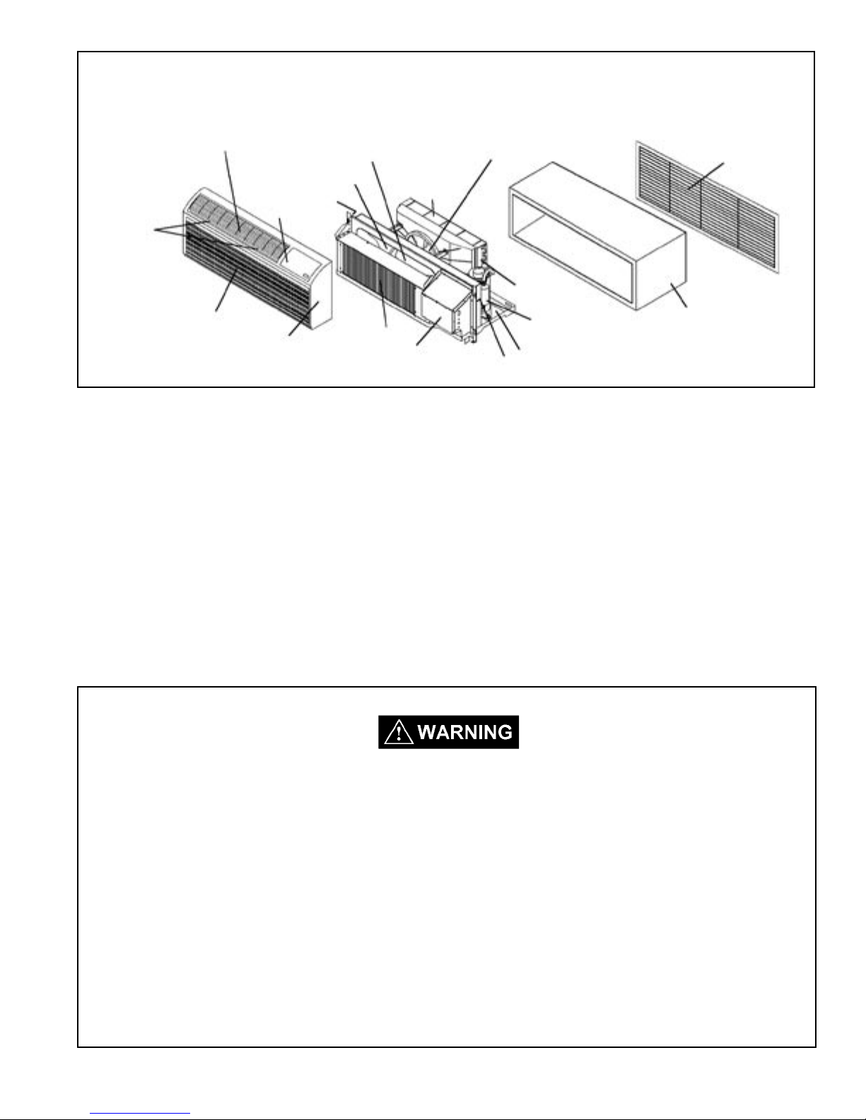
Typical Unit Components
Discharge Air Grille
Filters
Return Air Grille
Blower Wheel
Indoor Blower Housing
Gasket
Control Door
Evaporator Coil
Front Cover
Condenser
Control Panel
Condenser Fan Blade
Shroud
Gasket
Condenser
Coil
Compressor
Basepan
Outdoor Grille
Wall Sleeve
INTRODUCTION
This service manual is designed to be used in conjunction with the installation manuals provided with each air
conditioning system component.
This service manual was written to assist the professional HVAC service technician to quickly and accurately
diagnose and repair any malfunctions of this product.
This manual, therefore, will deal with all subjects in a general nature. (i.e. All text will pertain to all models).
IMPORTANT: It will be necessary for you to accurately identify the unit you are
servicing, so you can be certain of a proper diagnosis and repair. (See
Unit Identication.)
The information contained in this manual is intended for use by a qualied service technician
who is familiar with the safety procedures required in installation and repair, and who is equipped
with the proper tools and test instruments.
Installation or repairs made by unqualied persons can result in hazards subjecting the
unqualied person making such repairs to the risk of injury or electrical shock which can be
serious or even fatal not only to them, but also to persons being served by the equipment.
If you install or perform service on equipment, you must assume responsibility for any bodily
injury or property damage which may result to you or others. Friedrich Air Conditioning
Company will not be responsible for any injury or property damage arising from improper
installation, service, and/or service procedures.
3
5
UNIT IDENTIFICATION
Model Number Code
P H 07 K 3 S B 1
Series
P = P series
System
X= Accessory
E= Cooling with or
without electric heat
H = Heat Pump with
Auxiliary Heat
Nominal Cooling Capacity
07 = 7,000 - 7,100 BTUh
09 = 9,000 - 9,100 BTUh
12 = 11,500 - 11,700 BTUh
15 = 14,100 - 14,200 BTUh
Engineering Digit
Design Series
Options
S = Standard
R = Remote Thermostat
C = Seacoast Protection
X = Seacoast Remote
Nominal Heater Size
(@ 230V or 265V)
0 = No Heater
2 = 2.5 KW
3 = 3.4 KW
5 = 5.0 KW
Voltage
K = 230/208V - 1Ph. - 60 Hz.
R = 265V - 1Ph. - 60 Hz.
PTAC Serial Number Identication Guide
Serial Number
Decade Manufactured
L=0 C=3 F=6 J=9
A=1 D=4 G=7
B=2 E=5 H=8
Year Manufactured
A=1 D=4 G=7 K=0
B=2 E=5 H=8
C=3 F=6 J=9
Month Manufactured
A=Jan D=Apr G=Jul K=Oct
B=Feb E=May H=Aug L=Nov
C=Mar F=Jun J=Sep M=Dec
4
L B L P 00000
Production Run Number
PRODUCT LINE
R=RAC
P=PTAC
E=EAC
V=VPAK
H=Split
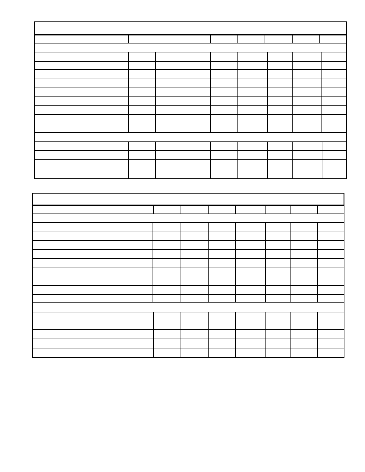
GENERAL INFORMATION – PE SERIES
Model PE07K PE07R PE09K PE09R PE12K PE12R PE15K PE15R
POWER
VOLTAGE (1 PHASE, 60 Hz) 230/208 265 230/208 265 230/208 265 230/208 265
VOLT RANGE 253-198 292-239 253-198 292-239 253-198 292-239 253-198 292-239
POWER (WATTS) 615/598 615 800/783 800 1091/1073 1091 1579/1578 1579
CURRENT (AMPS) 3 3 3.9 3.9 5.1 5.1 6.6 6.6
POWER FACTOR 0.9 0.9 0.9 0.9 0.9 0.9 0.9 0.9
AMPS L.R. 18 18 22.2 22.2 26.3 26.3 38 38
AMPS F.L. 3 3 3.9 3.9 5.1 5.1 6.8 6.8
HORSEPOWER 1/15. 1/15. 1/12. 1/12. 1/10. 1/10. 1/10. 1/10.
R-22 CHARGE (OZ) 27 27 30 30 28 28 28 28
PERFORMANCE
COOLING BTUh 7500/7300 7500 9200/9000 9200 12000/11800 12000 15000/14800 15000
INDOOR CFM 250 250 300 300 325 325 350 350
SENSIBLE HEAT RATIO 0.79 0.79 0.76 0.76 0.76 0.76 0.75 0.75
VENT CFM 60 60 60 60 70 70 70 70
GENERAL INFORMATION – PH SERIES
Model PH07K PH07R PH09K PH09R PH12K PH12R PH15K PH15R
POWER
VOLTAGE (1 PHASE, 60 Hz) 230/208 265 230/208 265 230/208 265 230/208 265
VOLT RANGE 253-198 292-239 253-198 292-239 253-198 292-239 253-198 292-239
POWER (WATTS) 590/574 590 791/774 791 1121/1023 1121 1581/1559 1559
CURRENT (AMPS) 3 3 3.9 3.9 5.1 5.1 6.6 6.6
POWER FACTOR 0.9 0.9 0.9 0.9 0.9 0.9 0.9 0.9
AMPS L.R. 18 18 22.2 22.2 26.3 26.3 38 38
AMPS F.L. 3 3 3.9 3.9 5.1 5.1 6.8 6.8
HORSEPOWER 1/15. 1/15. 1/12. 1/12. 1/10. 1/10. 1/10. 1/10.
R-22 CHARGE (OZ) 27 27 32 32 34.5 34.5 33 33
PERFORMANCE
COOLING BTUh 7200/7000 7000 9100/8900 9100 12000/11800 12000 14700/14500 14700
REVERSE HEATING BTUh 6400/6200 6400 8100/7900 8100 10800/10600 10800 13500/13300 13500
INDOOR CFM 250 250 300 300 325 325 350 350
SENSIBLE HEAT RATIO 0.79 0.79 0.76 0.76 0.76 0.76 0.75 0.75
VENT CFM 60 60 60 60 70 70 70 70
5
7
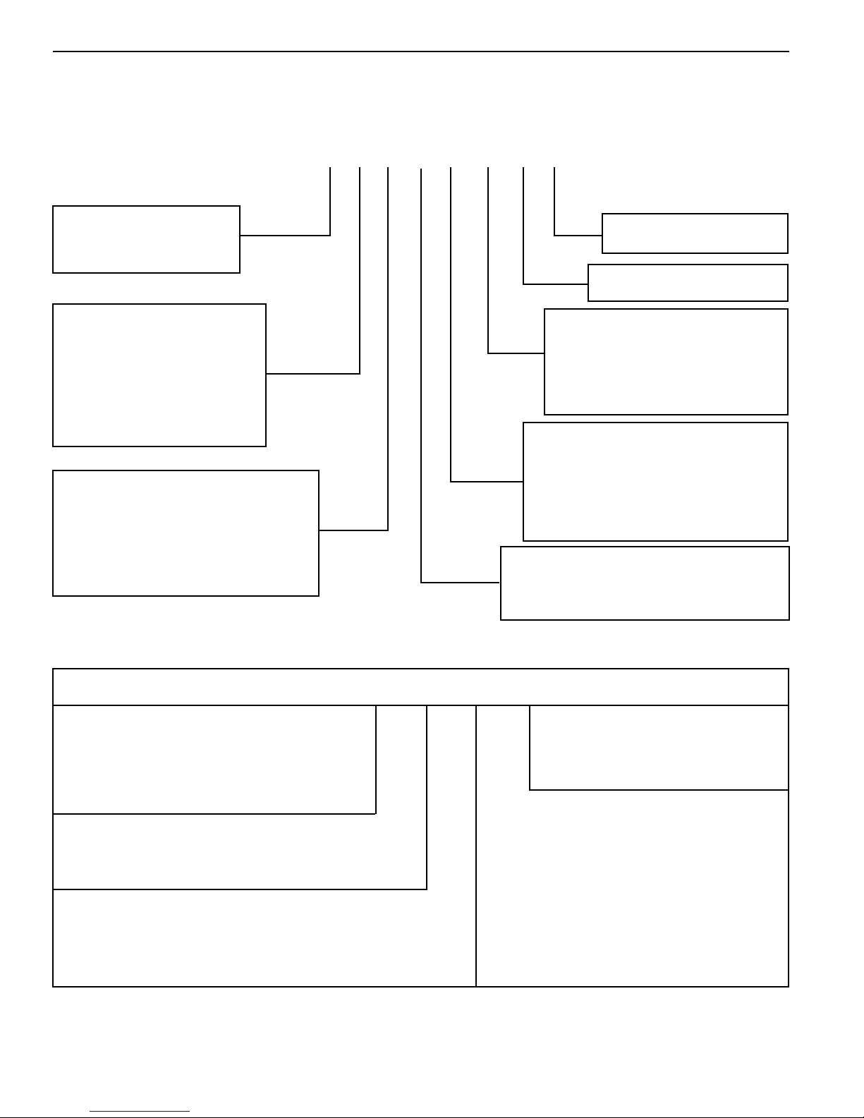
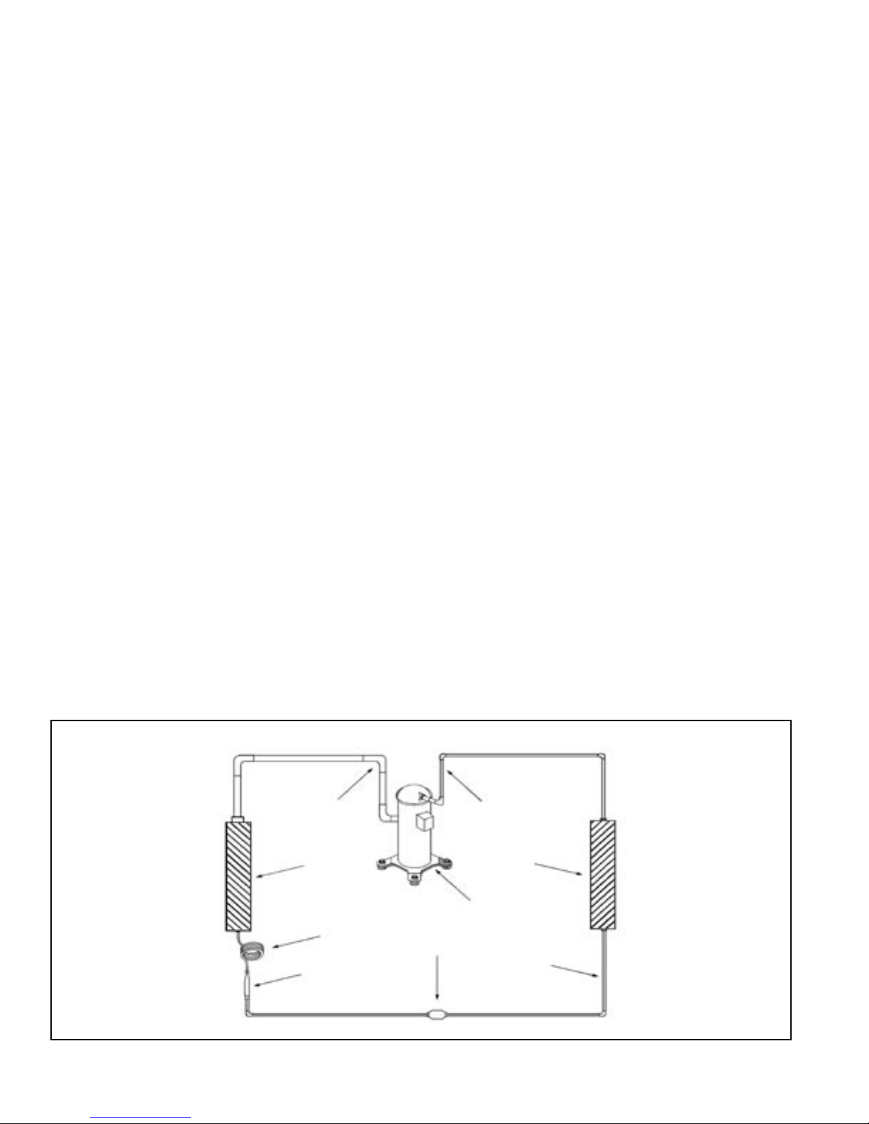
Sequence of Operation
A good understanding of the basic operation of the refrigeration
system is essential for the service technician. Without this
understanding, accurate troubleshooting of refrigeration system
problems will be more difcult and time consuming, if not (in some
cases) entirely impossible. The refrigeration system uses four
basic principles (laws) in its operation they are as follows:
1. "Heat always ows from a warmer body to a cooler body."
2. "Heat must be added to or removed from a substance before
a change in state can occur"
3. "Flow is always from a higher pressure area to a lower
pressure area."
4. "The temperature at which a liquid or gas changes state is
dependent upon the pressure."
The refrigeration cycle begins at the compressor. Starting the
compressor creates a low pressure in the suction line which draws
refrigerant gas (vapor) into the compressor. The compressor then
"compresses" this refrigerant, raising its pressure and its (heat
intensity) temperature.
The refrigerant leaves the compressor through the discharge Line
as a hot High pressure gas (vapor). The refrigerant enters the
condenser coil where it gives up some of its heat. The condenser
fan moving air across the coil's nned surface facilitates the transfer
of heat from the refrigerant to the relatively cooler outdoor air.
When a sufcient quantity of heat has been removed from the
refrigerant gas (vapor), the refrigerant will "condense" (i.e. change
to a liquid). Once the refrigerant has been condensed (changed)
to a liquid it is cooled even further by the air that continues to ow
across the condenser coil.
The PTAC design determines at exactly what point (in the
condenser) the change of state (i.e. gas to a liquid) takes place.
In all cases, however, the refrigerant must be totally condensed
(changed) to a Liquid before leaving the condenser coil.
The refrigerant leaves the condenser Coil through the liquid line
as a warm high pressure liquid. It next will pass through the
refrigerant drier (if so equipped). It is the function of the drier to
trap any moisture present in the system, contaminants, and large
particulate matter.
The liquid refrigerant next enters the metering device. The
metering device is a capillary tube. The purpose of the metering
device is to "meter" (i.e. control or measure) the quantity of
refrigerant entering the evaporator coil.
In the case of the capillary tube this is accomplished (by design)
through size (and length) of device, and the pressure difference
present across the device.
Since the evaporator coil is under a lower pressure (due to the
suction created by the compressor) than the liquid line, the liquid
refrigerant leaves the metering device entering the evaporator coil.
As it enters the evaporator coil, the larger area and lower pressure
allows the refrigerant to expand and lower its temperature (heat
intensity). This expansion is often referred to as "boiling". Since
the unit's blower is moving indoor air across the nned surface
of the evaporator coil, the expanding refrigerant absorbs some of
that heat. This results in a lowering of the indoor air temperature,
hence the "cooling" effect.
The expansion and absorbing of heat cause the liquid refrigerant
to evaporate (i.e. change to a gas). Once the refrigerant has been
evaporated (changed to a gas), it is heated even further by the air
that continues to ow across the evaporator coil.
The particular system design determines at exactly what point (in
the evaporator) the change of state (i.e. liquid to a gas) takes place.
In all cases, however, the refrigerant must be totally evaporated
(changed) to a gas before leaving the evaporator coil.
The low pressure (suction) created by the compressor causes
the refrigerant to leave the evaporator through the suction line
as a cool low pressure vapor. The refrigerant then returns to the
compressor, where the cycle is repeated.
Suction
Line
6
Evaporator
Coil
Metering
Device
Refrigerant
Strainer
Discharge
Line
Compressor
Refrigerant Drier
Condenser
Coil
Liquid
Line
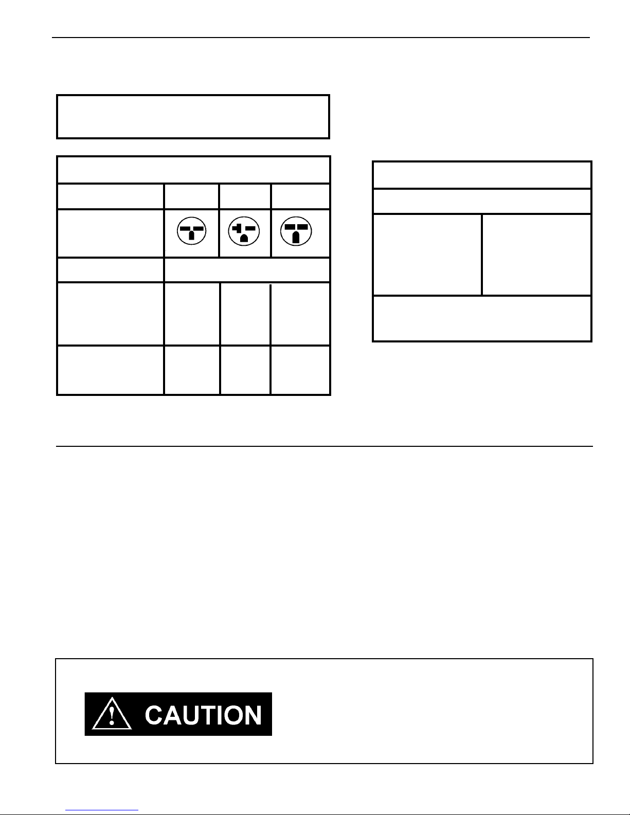
Electrical Rating Tables
All 230/208 volt units are equipped with power cords.
NOTE: Use Copper Conductors ONLY
Wire sizes are per NEC, check local
codes for overseas applications
Table 1 250 V Receptacles and Fuse Types
AMPS 15 20 * 30
RECEPTACLE
MANUFACTURER PART NUMBERS
Hubbell 5661 5461 9330
P & S 5661 5871 5930
GE GE 4069-1 GE4182-1 GE4139-3
Arrow-Hart 5661 5861 5700
TIME-DELAY TYPE
FUSE 15 20 30
(or HACR circuit breaker)
HACR — Heating, Air conditioning, Refrigeration
* May be used for 15 Amp applications if fused for 15 Amp
NOTE: 265 volt units are permanently connected.
Table 2
Recommended branch circuit wire sizes
Nameplate
AWG Wire size**
maximum circuit
breaker size
15 14
20 12
30 10
AWG — American Wire Gauge
* Single circuit from main box
** Based on copper wire, single insulated
conductor at 60°C
Wire Size Use ONLY wiring size recommended for single outlet branch circuit.
Fuse/Circuit Use ONLY type and size fuse or HACR circuit breaker indicated on unit's rating plate. Proper
Breaker current protection to the unit is the responsibility of the owner.
NOTE: A time delay fuse is provided with 265V units.
Grounding Unit MUST be grounded from branch circuit through service cord to unit, or through separate ground
wire provided on permanently connected units. Be sure that branch circuit or general purpose outlet
is grounded.
Receptacle The eld supplied outlet must match plug on service cord and be within reach of service cord.
Refer to Table 1 for proper receptacle and fuse type. Do NOT alter the service cord or plug. Do
NOT use an extension cord.
Wire Sizing Use recommended wire size given in Table 2 and install a single branch circuit. All wiring must
comply with local and national codes. NOTE: Use copper conductors only.
Electric shock hazard.
Turn off electric power before service or installation.
All electrical connections and wiring MUST be installed by a qualied electrician
and conform to the National Electrical Code and all local codes which have
jurisdiction.
Failure to do so can result in property damage, personal injury and/or death.
7
9
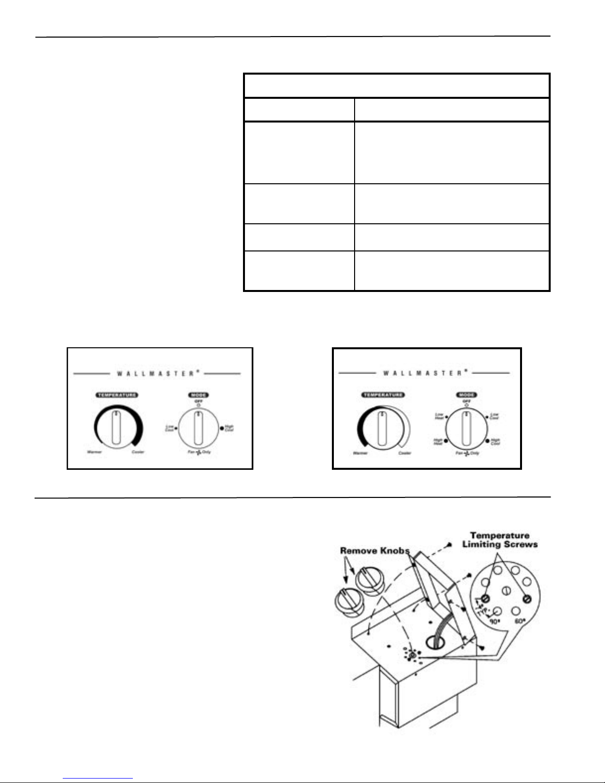
Standard Unit Operation
Rotary Switch Operation
Rota t e the te m p e r a t u r e dial i n small
increments in the warmer or cooler direction.
Moving the dial more than 1/4" at a time may
overcompensate and result in an extreme hot
or cold situation.
Standard Unit Control Panel
Control
Temperature
Low and High Cool
Low and High Heat
Fan Only
Operation
The full-range thermostat maintains room
temperature at the desired setting in both
the heating and cooling modes. Turn the
dial counterclockwise for warmer and
clockwise for a cooler temperature.
Operates the unit on cooling. Cooling
will not begin if the room temperature is
below 60°F.
Operates the unit on heating. Some
models do not provide this selection.
Circulates air within the room at high
fan speed only. No heating or cooling
functions are active.
COOLING ONLY MODEL
Temperature Limiting Thermostat
1. Set the thermostat knob to center of dial.
2. Remove the four screws holding the control panel. Pull up
on the thermostat knob and remove it.
3. Locate the two temperature limiting screws. These screws
are factory installed for a maximum temperature range of 60°90°F. Each hole in the dial plate represents approximately
a 4° change from the adjacent hole.
4. To adjust the temperature range, move the temperature
limiting screws to the desired location.
5. Replace the knob when the desired range has been set.
6. Replace the control panel.
EXAMPLE: To set a maximum temperature range of
approximately 64° to 86°F, move the screws to
the locations shown in the diagram at right.
8
HEAT/COOL MODEL
Remote Thermostat Unit Installation
1. Remote Thermostat Selection & Wiring Guidelines for Packaged
Terminal Air Conditioners
Follow the instructions and recommendations of the thermostat manufacturer for installation and wiring. Do not
use a conventional heat pump thermostat with emergency electric heat selection for our heat pump units. Our
units make an automatic decision about turning on electric heat if the heating demand cannot be met by the heat
pump due to low outdoor temperatures.
Manual Changeover Thermostat
For Heat Pump equipped units: A single stage, heat/cool thermostat with a terminal for a reversing valve operation
is required. Terminal "B" should be continuously energized in the heat mode and terminal "G" should be energized
whenever there is a call for heating or cooling. Typically, a heat/cool thermostat designed for use with electric heat
systems will meet the above requirements.
NOTE: This unit is designed for use with a single stage thermostat only. Improper application of the
thermostat may result in property damage, personal injury or death.
Honeywell Thermostat Terminal Designation
TERMINAL LETTER
Y
W
(Heat Pump units Only)
For Non-Heat Pump equipped units: A single stage cooling and heating thermostat is required. Terminal "G"
should be energized whenever a call for heating or cooling is made. Typically a heat/cool thermostat designed
for use with electric heat systems will meet this requirement.
G
C (common)
R
B
OPERATION
Cooling
Heating
Common Terminal
24 V
to the thermostat
Fan
Reversing Valve
CONTACT MADE
During call for cooling.
During call for heating.
Continuous if the slider is in the "Fan"
position, otherwise, intermittent.
For thermostats requiring a common
terminal
Directly from the transformer
Made continuously during call for
heating.
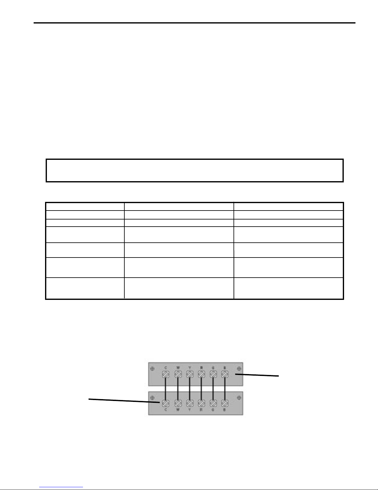
Simplified Wiring Example
Unit Terminal Board
* A-Sufx models do not have a "C" terminal
Terminal "C"
is not used on RT1
thermostat
Terminal "B" is
used for heat pump
models only.
NOTE: It is the installer's responsibility to ensure that all control wiring connections are made in accordance with
the installation instructions. Improper connection of the thermostat control wiring and/or tampering with the unit's
internal wiring can void the equipment warranty and may result in property damage, personal injury or death. Other
manufacturer's PTACs and even older Friedrich models may have different control wire connections. Questions
concerning proper connections to the unit should be directed to the factory.
Thermostat Terminals
9
11
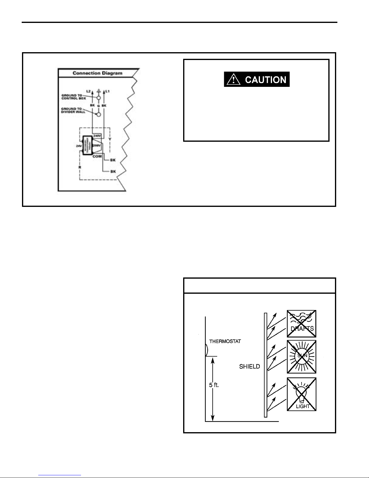
Remote Thermostat 208V Operation
208V 60HZ
If the supply voltage is 208V, the low voltage
transformer MUST be wired for 208V operation.
Failure to do so will result in lower control
voltages to the unit and can damage low voltage
components.
The simplied connection diagram at left shows the
factory congured wiring set for 240V operation. If you
are going to use 208V exclusively, switch the two (2)
black wires on the 240V post of the primary side of the
transformer to the 208V post. This will ensure correct
secondary (low) voltages for the unit. This is only required
on remote thermostat units.
Remote Thermostat Unit Operation
These units are controlled by the use of a remote
thermostat that will cycle the unit to maintain desired
room temperature. See thermostat operating instruction
sheet for details.
The fan speed switch controls high and low speed
fan operation. It is located on the control panel and is
independent of the thermostat.
Room Thermostats
Room thermostats are available from several different
manufacturers in a wide variety of styles. They range
from the very simple Bimetallic type to the complex
electronic set-back type. In all cases, no matter how
simple or complex, they are simply a switch (or series of
switches) designed to turn equipment (or components)
"ON" or "OFF" at the desired conditions.
An improperly operating, or poorly loca ted room
thermostat can be the source of perceived equipment
problems. A careful check of the thermostat and wiring
must be made then to insure that it is not the source of
problems.
the oor in an area of average temperature, with good air
circulation. Close proximity to the return air grille is the
best choice.
Mercury bulb type thermostats MUST be level to control
temperature accurately to the desired set-point. Electronic
digital type thermostats SHOULD be level for aesthetics.
Thermostat Location
Location
The thermostat should not be mounted where it may be
affected by drafts, discharge air from registers (hot or
cold), or heat radiated from the sun or appliances.
The thermostat should be located about 5 Ft. above
10

Measuring Current Draw
Heat Anticipators
Heat anticipators are small resistance heaters (wired
in SERIES with the "W" circuit) and built into most
electromechanical thermostats. Their purpose is to prevent
wide swings in room temperature during system operation
in the HEATING mode. Since they are wired in series,
the "W" circuit will open if one burns out preventing heat
operation.
The heat anticipator provides a small amount of heat to
the thermostat causing it to cycle (turn off) the heat source
just prior to reaching the set point of the thermostat. This
prevents exceeding the set point.
If a low range ammeter is not available, a "Clamp-on" type
ammeter may be used as follows:
1. Wrap EXACTLY ten (10) turns of wire around the jaws
of a clamp-on type ammeter.
2. Connect one end of the wire to the "W" terminal of
the thermostat sub-base, and the other to the "R"
terminal.
3. Turn power on, and wait approximately 1 minute, then
read meter.
4. Divide meter reading by 10 to obtain correct anticipator
setting.
Electronic thermostats do not use a resistance type
anticipator. These thermostats use a microprocessor
(computer) that determines a cycle rate based on a program
loaded into it at the factory.
Calculating The Approximate CFM
The approximate CFM actually being delivered can be
calculated by using the following formula:
KILOWATTS x 3413
Temp. Rise x 1.08
In order to accomplish this, the heat output from the
anticipator must be the same regardless of the current
owing through it. Consequently, some thermostats have
an adjustment to compensate for varying current draw in
the thermostat circuits.
The proper setting of heat anticipators then is important to
insure proper temperature control and customer satisfaction.
A heat anticipator that is set too low will cause the heat
source to cycle prematurely possibly never reaching set
point. A heat anticipator that is set too high will cause the
heat source to cycle too late over shooting the set point.
The best method to obtain the required setting for the
heat anticipator, is to measure the actual current draw in
the control circuit ("W") using a low range (0-2.0 Amps)
ammeter. After measuring the current draw, simply set the
heat anticipator to match that value.
DO NOT simply use the Kilowatt Rating of the heater (i.e.
2.5, 3.4, 5.0) as this will result in a less-than-correct airow
calculation. Kilowatts may be calculated by multiplying the
measured voltage to the unit (heater) times the measured
current draw of all heaters (ONLY) in operation to obtain
watts. Kilowatts are then obtained by dividing by 1000.
EXAMPLE: Measured voltage to unit (heaters) is 230 volts.
Measured Current Draw of strip heaters is 11.0 amps.
230 x 11.0 = 2530
2530/1000 = 2.53 Kilowatts
2.53 x 3413 = 8635
Supply Air 95°F
Return Air 75°F
Temperature Rise 20°
20 x 1.08 = 21.6
8635
21.6
= 400 CFM
= CFM
11
13
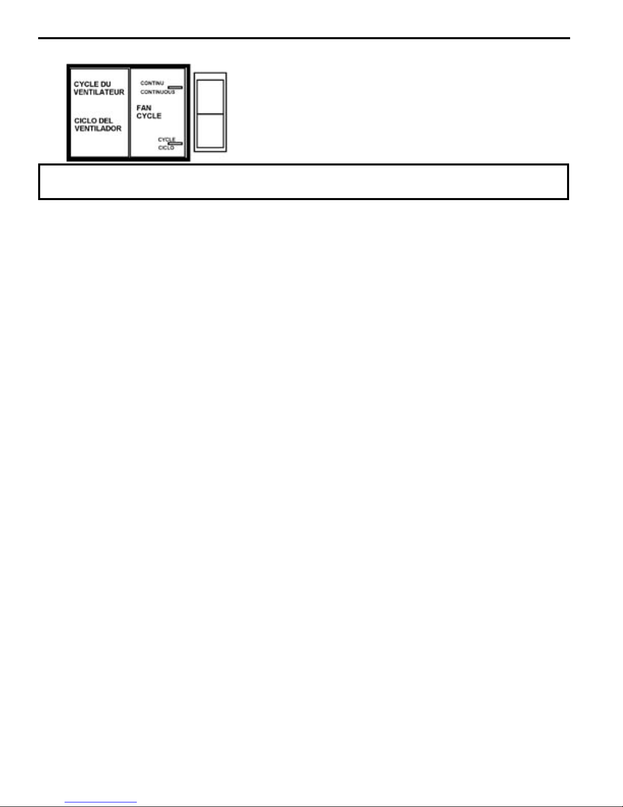
Fan Cycle Switch
NOTE: It is recommended that this switch be set in the continuous position for maximum comfort and
temperature control.
The fan cycle switch is located behind the decorative front
cover below the control box. It is designed to operate the fan
either continuously or intermittently with the compressor or
heating elements. When the switch is in the CONTINUOUS
position, the fan will run continuously when the unit is turned
on. With the fan cycle switch in the CYCLE position, the
fan will run only when the compressor or heating elements
cycle on.
Hot Start Sensor
(Heat Pump Models Only)
Under cold room conditions, the Hot Start Sensor brings
on the heater strips with a call for heat. This is to distribute warm air at the beginning of the heat cycle. Once
the return air has warmed sufciently, the heat pump
mode will begin.
Refrigerant Charging
NOTE: Because The Ptac System Is A Sealed System,
Service Process Tubes Will Have To Be Installed.
First Install A Line Tap And Remove Refrigerant From
System. Make Necessary Sealed System Repairs And
Vacuum System. Crimp Process Tube Line And Solder
End Shut. Do Not Leave A Service Valve In The Sealed
System.
Proper refrigerant charge is essential to proper unit
operation. Operating a unit with an improper refrigerant
charge will result in reduced performance (capacity) and/or
efciency. Accordingly, the use of proper charging methods
during servicing will insure that the unit is functioning as
designed and that its compressor will not be damaged.
Too much refrigerant (overcharge) in the system is just as
bad (if not worse) than not enough refrigerant (undercharge).
They both can be the source of certain compressor failures if
they remain uncorrected for any period of time. Quite often,
other problems (such as low air ow across evaporator,
etc.) are misdiagnosed as refrigerant charge problems. The
refrigerant circuit diagnosis chart will assist you in properly
diagnosing these systems.
Not enough refrigerant (undercharge) on the other hand,
will cause the temperature of the suction gas to increase to
the point where it does not provide sufcient cooling for the
compressor motor. When this occurs, the motor winding
temperature will increase causing the motor to overheat
and possibly cycle open the compressor overload protector.
Continued overheating of the motor windings and/or cycling
of the overload will eventually lead to compressor motor
or
overload failure.
Method Of Charging
The acceptable method for charging the PTAC system is
the Weighed in Charge Method. The weighed in charge
method is applicable to all units. It is the preferred method
to use, as it is the most accurate.
The weighed in method should always be used whenever
a charge is removed from a unit such as for a leak repair,
compressor replacement, or when there is no refrigerant
charge left in the unit. To charge by this method, requires
the following steps:
1. Install a piercing valve to remove refrigerant from the
sealed system. (Piercing valve must be removed from
the system before recharging.)
2. R e c o v e r Re f r i g e r a n t in accordance with EPA
regulations.
3. Install a process tube to sealed system.
4. Make necessary repairs to system.
An overcharged unit will at times return liquid refrigerant
(slugging) back to the suction side of the compressor
eventually causing a mechanical failu re within the
compressor. This mechanical failure can manifest itself
as valve failure, bearing failure, and/or other mechanical
failure. The specic type of failure will be inuenced by the
amount of liquid being returned, and the length of time the
slugging continues.
12
5. Evacuate system to 300 microns or less.
6. Weigh in refrigerant with the property quantity of R-22
refrigerant.
7. Start unit, and verify performance.
8. Crimp the process tube and solder the end shut.
 Loading...