

Page 1
Model PDXWS
Installation Instructions
WALL SLEEVE
For Use With Packaged Terminal Units
Please read these instructions completely before attempting installation.
NOTE: These instructions apply to installation of the wall sleeve only through walls structurally adequate to support the unit
(i.e. sleeve, chassis, accessories.) If wall is not structurally adequate, a subbase or other means of support MUST be made.
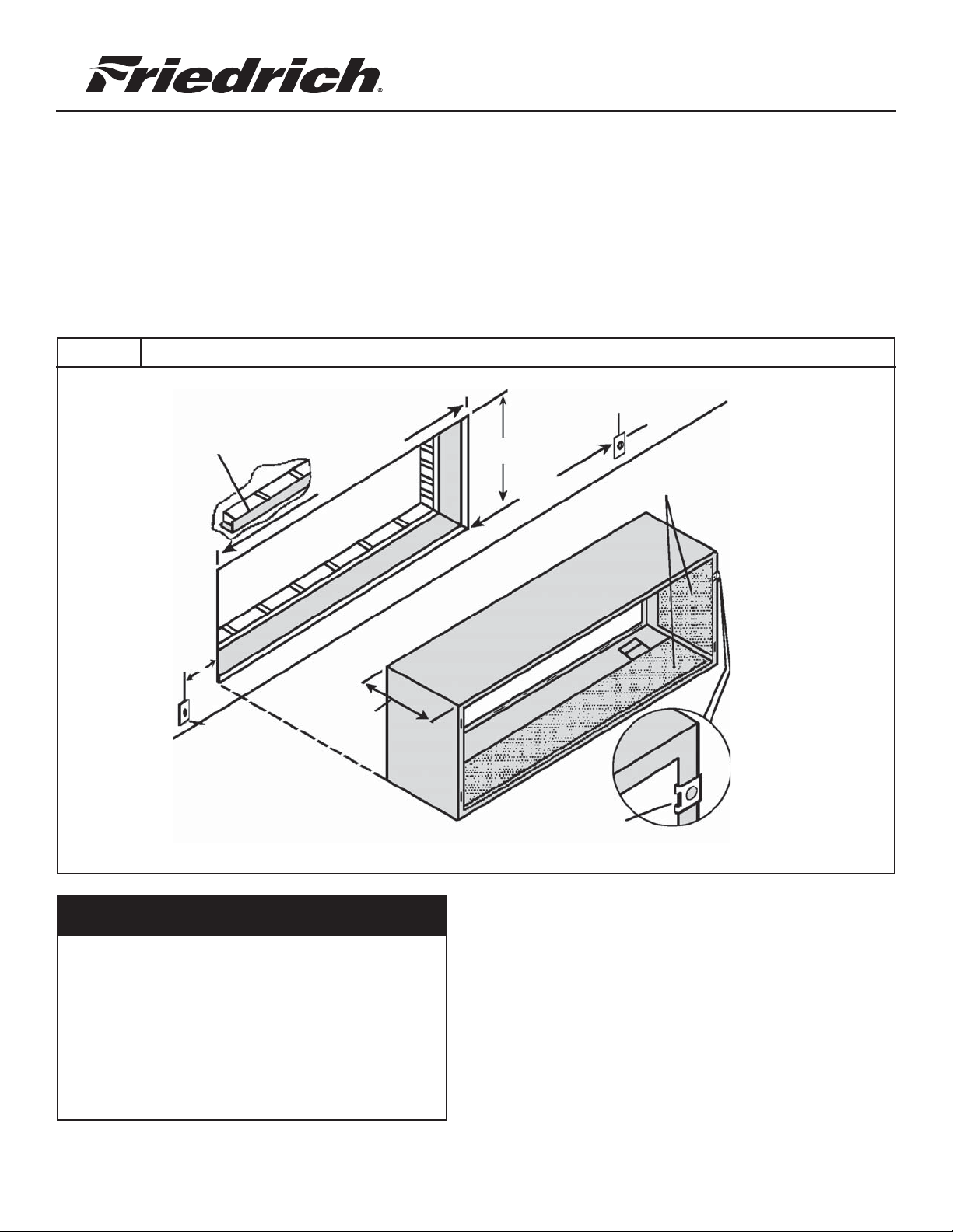
Figure 1. Typical Wall Sleeve Installation
Electrical
Receptacle
Lintel Used To Support
Masonry Walls
42¼"
Minimum
16¼"
Maximum
50"
Insulation
Wall Opening
10" Maximum
13¾"
Electrical
Receptacle
WARNING
Electrical shock hazard.
Turn OFF electric power at fuse box or service panel
before making any electrical connections and ensure a
proper ground connection is made before connecting
line voltage.
Smooth side of
clip on Room side.
Wall Opening
Refer to Figures 1 and 2 for proper dimensions and
location of wall opening and placement of electrical
receptacle.
Failure to do so can result in property damage,
personal injury and/or death.
920-078-01 (12-04)
Page 2

SECTION I
Drain Kit
A field supplied condensate drain kit is required for total
elimination of cooling or heat pump condensate.
When installing a condensate drain kit, (either internal or external drain), it is recommended that installation of the drain
kit be completed before installing the wall sleeve. Instructions
for drain kit installation are shipped with the drain kit.
Wall Structure
3. Drill two 3/16" holes through each side of the sleeve
approximately 4" from top and 4" from bottom of sleeve.
Screw four #10 x 1" screws (included) or appropriate
fasteners for your installation, through holes in sides of
opening.
NOTE: Do NOT put any screws or drill any holes in the bottom
of wall sleeve, unless required by the installation of a PXDR10
Condensate Drain Kit.
A subbase or other means of support MUST be used if sleeve
projects more than 8" into room. Refer to subbase installation
instructions for additional information.
Sleeve Installation
For Deep Wall Installation See Section II
The following instructions apply ONLY to walls less than 13
1/4"" in depth.
1. From inside the building, position wall sleeve in opening
and push through the wall so it protrudes at least 1/4"
on the outside, note Figure 2.
2. Position the wall sleeve so that it is positioned with a
slight tilt towards the outside to facilitate condensate
drainage. It should be level side-to-side. DO NOT allow
any pitch toward the inside.
Figure 2. Dimensions
4. Apply sealant around the wall sleeve where it projects
through the inside and outside wall surfaces. Apply
sealant to screw heads or tops of fasteners used in Step
#3.
NOTE: When sealing sleeve on outside of building, be care-
ful NOT to let sealant block the two condensate drain
holes or the four overflow slots at the bottom flange of
the sleeve.
5. If chassis and exterior louver are to be installed later,
leave the weatherboard and center support in place,
otherwise remove and dispose of them.
Dimension* A (Minimum) B
(See Note)
Min. Max.
13¾"
Wall
** To allow for wall/fl oor fi nishing.
¼"
Minimum
No
Accessories
With
Outdoor
Grille
Subbase 1 3/4" 3 1/2" 5"
With
Lateral Duct 3/4" 1/4" —
Caulking
NOTES
* If more than one accessory is to be
used, use the worst case dimension.
If the wall thickness is more than 13 3/4" - (A + 1/4"),
a sleeve extension MUST be used.
**1/4" 1/4" —
Page 3

Figure 3. Lintel Installation
MAIN STUDS
JACK STUD
LINTEL
MOUNTING
SCREW HOLE
No holes are permitted
in the bottom of the
case. (Exception:
PXDR10 Drain Kit)
Note the use of a lintel under the first course of bricks
above the wall sleeve. Do not use the wall sleeve as a lintel. The mounting screw holes shown are to be made by the
installer.
6. Provide a support lintel if the wall sleeve is installed in a concrete or masonry wall. (See Figure 3)
Page 4

SECTION II
Deep Wall Installation
If wall is thicker than allowed in the notes in Figure 2, a sheet
metal wall sleeve extension and flashing MUST be used. See
Figure 4 for guidelines to use in fabricating a wall sleeve extension.
Field Fabricating A Sleeve Extension
The Following points MUST be considered when designing a
wall sleeve extension.
1. Provision must be made to direct excess condensate from
the back of the wall sleeve to the outside of the building.
2. Air baffles must be mounted to properly direct air flow
from the condenser.
3. Wall Sleeve Extension design must allow for the proper
mounting of the louvers.
4. Caulking of all potential sites where condensate or external
water could infiltrate into building is required.
6. Condensate notches are clear of sealant so condensate
flows freely into extension.
NOTE: Improper fabrication of a wall sleeve extension will
impair PTAC performance. Regardless of your final extended
wall sleeve design, provision MUST be made for proper direction of air flow and condensate.
Extension Installation
Size wall sleeve extension to fit frame opening. Secure it to
wall sleeve before installing in the wall. Refer to Figure 4
the
for a
guide for fabrication of a condensate drip panel. Panel MUST
extend the full depth of the wall sleeve and the wall sleeve
extension. Pay particular care in sealing and caulking the panel
where it makes contact with the wall sleeve (see Figure 4.)
After installation in the wall, secure with fasteners through the
sides. Seal around the sleeve extension with exterior caulking.
Using a good grade of silicone sealant, seal all exposed screw
heads. When installation is complete, outside louver may be
attached to wall sleeve extension.
5. Seal strips must be attached to the outside edge of the
vertical baffles.
Figure 4. Extended Wall Sleeve and Sealant Locations
IMPORTANT NOTE: The silicone bead MUST extend 3" up
the side of the two flanges to prevent condensate from
leaking.
Wall Sleeve
Outside Edge
Insulation
Air Baffles
Condensate
Width of wall
Drip
Edge
Drip Panel
(Field
Supplied)
Condensate
Notches
Sealant inside (4)
bottom corners
920-078-01 (12-04)
42 X 16" Frame, 20 gauge minimum,
painted or aluminium
 Loading...