

Page 1
Model PDXDAA & PDXDEA
Installation Instructions
Lateral Duct Accessory Kit
For Use with F Series Packaged Terminal Air Conditioner or Heat Pump
Introduction:
These instructions cover the installation of the Lateral Duct Accessory Kit for Packaged Terminal Air
Conditioner (PTAC) units. Please read these instructions completely before attempting installation.
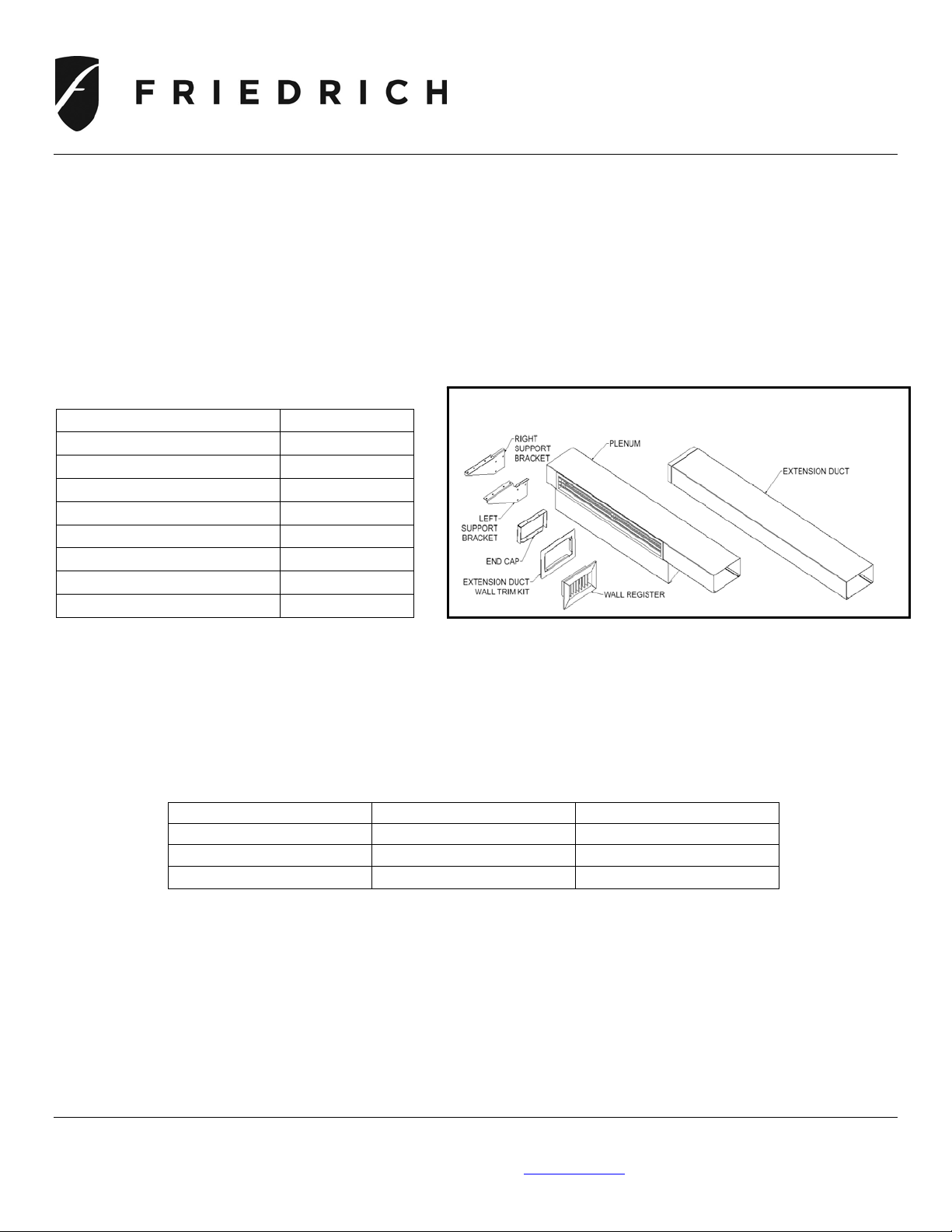
Package Contents (See Fig 1):
ITEM QUANTITY
Plenum 1
Extension Duct 1
Extension Duct Wall Trim Kit 1
Wall Register 1
End Cap 1
Attachment Screws 14
Right Support Bracket 1
Left Support Bracket 1
Tools Required: Power drill, 1/8” drill bit, hacksaw, Phillips screwdriver and utility knife.
General
The Lateral Duct Accessory Kit allows one PTAC unit to heat or cool two rooms. The kit mounts to
the wall sleeve and can be installed for either right or left side duct applications. The amount of air
that can be diverted to an adjoining room is adjustable from 20 to 30 percent. (See Table 1)
Table 1 – Airflow Adjustments
BAFFLE POSITION UNIT FRONT ADJACENT ROOM
Position 1 (factory default) 80% 20%
Position 2 75% 25%
Position 3 70% 30%
Pre-Installation
Consider the following before installing the Lateral Duct Accessory:
• Maximum duct extension length is 4 feet.
• Duct run must be straight and horizontal; no bends or turns.
• Minimum recommended clearance between unit and adjoining room wall is 6 inches.
• Provisions must be made for return air from the adjoining room.
• The PTAC unit does not have to be removed for lateral duct installation.
PDXDAA & PDXDEA Friedrich Air Conditioning Co. Pg 1/5
Post Office Box 1540 / San Antonio, Texas 78295-1540
(210) 546-0500 / (800) 541-6645 / www.friedrich.com
Figure 1- Components for Lateral Duct Accessory Kit
Page 2
Model PDXDAA & PDXDEA
W
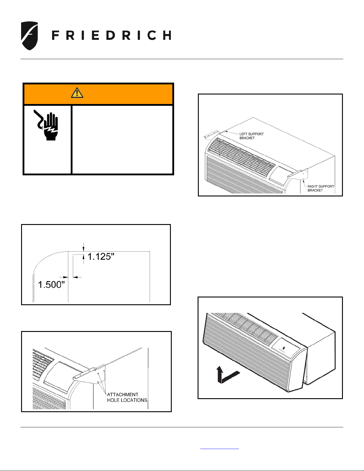
Installation
Mount Support Brackets to Wall Sleeve
1. Mark Top Hole location and line up bracket with
the bracket holes. See Fig 2.
Figure 2 – Side View of Metal Wall Sleeve
showing measurements for Top Hole Location.
2. Mark other 2 holes locations. See Fig. 3.
Figure 3 – Location of Attachment Holes
3. Drill all 3 holes with a 1/8-in. drill bit.
ARNING
Electrical Shock Hazard
Disconnect all electrical
power to unit before service
or installation. Failure to do
so can result in property
damage, personal injury
and/or death.
4. Secure bracket (be sure to use correct bracket
as there is a left and right bracket) with 3
screws provided.
Do not over tighten. See Fig. 4.
Figure 4 – Support Bracket Attached to Wall
Sleeve
5. Repeat procedure above for other side bracket
attachment.
Remove Discharge Grille and Control Door
from Front Panel
6. Remove front panel from unit by grasping the
panel firmly near the bottom of both sides, then
pulling the panel forward and upward to release
partition hooks. See Fig 5.
Figure 5 – Removing Front Panel
PDXDAA & PDXDEA Friedrich Air Conditioning Co. Pg 2/5
Post Office Box 1540 / San Antonio, Texas 78295-1540
(210) 546-0500 / (800) 541-6645 / www.friedrich.com
Page 3

Model PDXDAA & PDXDEA
7. Remove and discard discharge grille by
removing attachment screws from inside of
front panel. See Fig 6.
Figure 6 – Back View of Front Panel
8. Optional – for easy access to control panel,
remove the control door by removing the hinges
pins from inside of front panel that secure
control door in place.
9. Replace the front panel.
Install Extension Duct
(Use for Left or Right Applications)
10. Temporarily secure plenum to support brackets
previously installed.
11. Establish the position where the extension
should intersect the adjacent wall and mark this
location.
12. Measure and cut a 3
through the wall. See Fig. 7.
PDXDAA & PDXDEA Friedrich Air Conditioning Co. Pg 3/5
3/4 in. x 7 1/8 in. opening
Post Office Box 1540 / San Antonio, Texas 78295-1540
(210) 546-0500 / (800) 541-6645 / www.friedrich.com
Figure 7 – Side View Showing Measurements
for Extension Opening
13. The Extension Duct Wall Trim Kit can be used
to trim out, up to approximately a 1/2 inch gap
around the Extension Duct.
14. Establish the needed length of the Extension
Duct. Be sure to include the thickness of the
wall in determining the proper length. One
suggested method is to measure from the
support bracket to outer wall surface in the
adjacent room.
15. Cut the Extension Duct to length. Do not cut
flanged end as this is inserted into the plenum.
Only cut the non-flanged end of the Extension
Duct. See Fig 8.
Figure 8 – Extension Duct Attachment
Page 4

Model PDXDAA & PDXDEA
NOTE: The final length of duct may be cut to up to
½ in. short of outside of wall opening as the
Wall Register inner flange will cover this ½ in.
gap. This is to allow for flush mounting of the
Wall Register to the wall.
16. Trim the Extension Duct interior insulation back
approximately 1
wall register. See Fig 9.
Figure 9 – Trimmed Insulation in Extension Duct
Figure 10 – Completed Assembly of Plenum and Extension
1/2 in. to allow installation of
17. Mount extension duct by sliding extension duct
into the wall opening (or previously installed
wall trim kit mounted in the wall opening) and
secure flanged end with 2 screws provided, to
support bracket. See Fig 8 again.
Install Plenum to Unit
IMPORTANT: Unit must be mounted in sleeve
with front panel installed before attaching plenum.
18. Using two screws provided, install End Cap to
Plenum on side opposite from where Extension
Duct is attached.
19. Line hole up with Extension Duct on one side
and the support bracket on other side. Secure
with 4 screws provided. See Fig. 10 for
completed plenum assembly.
NOTE: Be sure plenum is tightly sealed to the front
panel.
PDXDAA & PDXDEA Friedrich Air Conditioning Co. Pg 4/5
Post Office Box 1540 / San Antonio, Texas 78295-1540
(210) 546-0500 / (800) 541-6645 / www.friedrich.com
Page 5

Model PDXDAA & PDXDEA
Install Wall Register
20. In adjacent room center the register on the duct
end and push into the duct until the frame is
tight to the wall.
NOTE: The clips on the register are designed to
hold it in place.
Adjust Volume of Airflow Between Rooms
NOTE: The plenum is factory set for maximum
discharge of airflow from front of unit. To adjust
the airflow between 2 rooms, adjust the internal
baffle as follows:
21. Remove plenum discharge grille.
The Installation of the Lateral Duct Accessory Kit is now complete.
Thank you for purchasing this Friedrich accessory.
Please contact us if you have comments or questions.
22. Remove 2 screws holding baffle. See Fig 11.
Figure 11 – Baffle Attachment Screw Locations
23. Position baffle, and secure for desired airflow
setting. See Table 1.
24. Replace plenum discharge grille.
PDXDAA & PDXDEA Friedrich Air Conditioning Co. Pg 5/5
Post Office Box 1540 / San Antonio, Texas 78295-1540
(210) 546-0500 / (800) 541-6645 / www.friedrich.com
 Loading...